Abstract
The present investigation addressed the entropy generation, fluid flow, and heat transfer regarding Cu-AlO-water hybrid nanofluids into a complex shape enclosure containing a hot-half partition were addressed. The sidewalls of the enclosure are made of wavy walls including cold isothermal temperature while the upper and lower surfaces remain insulated. The governing equations toward conservation of mass, momentum, and energy were introduced into the form of partial differential equations. The second law of thermodynamic was written for the friction and thermal entropy productions as a function of velocity and temperatures. The governing equations occurred molded into a non-dimensional pattern and explained through the finite element method. Outcomes were investigated for Cu-water, AlO-water, and Cu-AlO-water nanofluids to address the effect of using composite nanoparticles toward the flow and temperature patterns and entropy generation. Findings show that using hybrid nanofluid improves the Nusselt number compared to simple nanofluids. In the case of low Rayleigh numbers, such enhancement is more evident. Changing the geometrical aspects of the cavity induces different effects toward the entropy generation and Bejan number. Generally, the global entropy generation for Cu-AlO-water hybrid nanofluid takes places between the entropy generation values regarding Cu-water and AlO-water nanofluids.
1. Introduction
The investigation concerning convective heat transfer in enclosures and close cavities is an important issue that has enormous variety regarding purposes toward engineering and industry equipment, including heat exchangers [1], HVAC [2], cooling of electronic devices [3], and renewable energies [4]. In these applications, the selection of the heat transfer liquid is a crucial step to ensure an optimal heat transfer. In this regard, the use of pure liquids, such as water and oil, has shown an obstacle due to their low thermal conductivity. To overcome this disadvantage, nanoparticles (less than 100 nm in diameter) of materials with high thermal conductivity are combined with the carrier fluid to change its thermal properties and enhance heat transfer [5]. The suspensions of pure fluids containing such nanoparticles are referred to as nanofluids. The nanoparticles are mainly made of metals, such as Ag, Au, Cu, and Ni, or metal oxides like AlO, CuO, FeO, MgO, etc. [6]. Khanafer et al. [7] was the first to consider the natural convection concerning nanofluids into two-dimensional cavity and noted a substantial heat transfer improvement influenced with the presence of suspended nanoparticles. Jou and Tzeng [8] conducted a similar investigation in a rectangular cavity and showed that raising the volume fraction of nanoparticles can effectively increase the rate of heat transfer. Therefore, the initial studies overall agreed toward the impact of nanofluids on heat transfer augmentation [9,10].
Recently, various features concerning free convection heat transfer inside enclosures have been explored, for instance, the convection heat transfer about phase change materials [11], micropolar fluids [12,13], gyrotactic microorganisms liquids [14], magnetohydrodynamic flows [15], internal heat generation [16,17], and conjugate heat transfer [18,19] have been investigated in enclosures very recently. Dispersing of nanoparticles into a base liquid can improve the thermal conductivity and heat transfer rate. Heat transfer that concerning various nanofluids, such as silicon carbide–water [20], alumina water [21,22,23], and phase change composites [24,25] have been investigated.
The hybrid nanofluids are a newly engineered type of nanofluids which benefit from the properties of two or more types of nanoparticles. The convective heat transfer regarding hybrid nanofluids has been explored for various combination of nanoparticles such as single-wall and multiwall carbon nanotubes [26,27,28], FeO-single-wall carbon nanotube [29,30], Cu-AlO[31], and SiO-AlO [32]. The natural convection heat transfer holds the effects of buoyancy forces due to temperature difference in a fluid. In such flows, the fluid flow and heat transfer exist coupled. Thus, any change in the position of heat source, the geometry of enclosure or the working fluid could significantly alter the behavior of flow and heat transfer and consequently, the entropy generation. Due to such nonlinear coupled effects, the free convection heat transfer inside complex containers has been a hot topic during recent publications. For example, circular [33], C-shape [34], layered [35], Arc shape [36], complex wavy [37], and T-shape [38] cavities have been examined.
Entropy generation (production) concerns irreversibilities associated with friction forces and heat transfer due to temperature differences. The entropy production concerning natural convection heat transfer is an interesting subject, which continued investigated for simple fluids [39,40] and nanofluids [41]. Liu et al. [42] examined the entropy generation about alumina-water nanofluids in a tilted cavity. They found that raising the tilting angle about the cavity decreases the entropy generation. Selimefendigil and Öztop [43] studied the conjugate heat transfer including entropy generation of CuO-water nanofluids toward a cavity with a solid conductive partition. The results indicate that the change of the geometrical aspect of the cavity can notably change the portion of entropy generation in solid plus liquid regions.
The entropy production study of hybrid nanofluids is a new topic. Tayebi and Öztop [44] explored the free convection of alumina–copper–water hybrid nanofluids in an annulus within-pair elliptical horizontal cylinders. Outcomes show that growth of the Rayleigh number boosts both thermal and frictional entropy generation and consequently the entire entropy production. Moreover, both thermal and frictional entropy production terms raised through the appearance of hybrid nanoparticles. Tayebi and Chamkha [45] analyzed the entropy generation of alumina–copper–water hybrid nanofluids toward a square hollow including an inner conductive object. It was found that the internal object and its thermal conductivity significantly influence the entropy generation in the cavity. Using hybrid nanoparticles intensified the total entropy generation, but its effect on Bejan number was minimal.
The previous works have investigated the nanofluids inside regular enclosures. However, the hybrid nanofluid is a new subject in which the nanoparticles are a composite of at least two types of nanoparticles. The present study aims to investigate the flow and heat transfer of hybrid nanofluids within complex enclosures. Moreover, the literature review shows that the shape of the enclosure and presence of hybrid nanoparticles induce a complex effect toward natural convection flow, heat transfer, and entropy generation within a complex cavity. Therefore, new studies are demanded to improve the understanding of convection heat transfer and entropy generation of hybrid nanofluids inside complex shape cavities. The existing research aims to discuss the conjugate flow, heat transfer, and entropy generation of Cu-AlO-water hybrid nanofluid into a wavy wall complex cavity having hot half-partition.
2. Mathematical Formulation
Steady two-dimensional free convection flow and heat transfer is addressed inside a wavy enclosure among length L also holding a prominent isothermal heater at the bottom and solid blocks at the top with fixed length 0.25 L and width h, as illustrated in Figure 1. The prominent isothermal heater with length d and width h exists maintained by a fixed temperature (). The sidewalls about the enclosure are wavy walls with an isothermal cold temperature (). The top wall, as well as the bottom wall, are well insulated. All of the enclosure walls are impermeable walls with no-slip. The container does filled with a water-based hybrid nanofluid containing Cu-AlO nanoparticles. The buoyancy forces occur formed employing the Boussinesq approximation. With the respect of the assumptions mentioned above, the conservation of mass, momentum, and thermal energy for a laminar and Newtonian hybrid nanofluid obtain formulated as
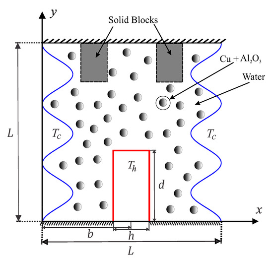
Figure 1.
Schematic view of the physical model, geometrical details, and the enclosure containing the inner solid blocks and the coordinate system.
The heat equation concerning the solid blocks is
where x and y are the Cartesian coordinates as illustrated in Figure 1, indicates the gravity acceleration, denotes the hybrid nanofluid’s density, indicates the hybrid nanofluid’s kinematic viscosity, and shows a reference temperature (310 K).
The effective physical properties of the hybrid nanofluid were applied in the form
where is the each of the thermophysical properties of the hybrid nanofluid heat capacitance (), density (), and buoyancy coefficient ().
The dynamic viscosity ratio of nanofluids was derived in [46] as
and the thermal conductivity ratio of hybrid nanofluids was evaluated by the Corcione et al. model [46] as
Based on these models, we are going to determine the dynamic viscosity ratio and the thermal conductivity ratio of water-Cu-AlO hybrid nanofluid for 33 and 29 nm particles as the following,
where of the hybrid nanofluid is defined as
Here, nm denotes the mean path of fluid particles, (J/K) is the Boltzmann constant, and shows the molecular diameter of water, which can be computed as [46]
where indicates the Avogadro number, M shows the base fluid’s molecular weight, and is the base fluid’s density at a reference temperature (310 K).
The following non-dimensional variables are introduced for modifying the governing equations into a general dimensionless format,
The general patterns of the governing equations are achieved as
Accordingly, the non-dimensional form of the boundary conditions Equations (14)–(18) are achieved as
where is the ratio of the solid block’s thermal conductivity to the hybrid nanofluid and S is the dimensionless length of the solid blocks.
The local Nusselt numbers are evaluated at the heated left, right, and upper surfaces of the source as the following,
and the total local Nusselt number is defined as:
Next, the average Nusselt numbers do estimate toward the heated vertical (left and right) surfaces of the source as
also, the average Nusselt number estimated toward the upper surface of the heat source, which exists as
and the total average Nusselt number is evaluated as the following,
The entropy generation is a combination of friction and thermal entropy generation, which can be computed by using the following relation,
Within the dimensionless pattern, local entropy generation can be revealed as
where denotes the irreversibility distribution ratio and .
Considering the two entropy source, the terms of Equation (36) are represented as two physical terms:
where and clarify the heat transfer irreversibility (HTI) and fluid friction irreversibility (FFI), respectively.
Now Equation (37) is integrated over the enclosure surface to computed the global entropy generation ():
Finally, the Bejan number is introduced in the following relation. The Bejan number represents the ratio of the thermal entropy generation to the total entropy generation. The Bejan number can be used to judge the dominant effect of HTI and FFI.
when , the HTI is dominant; otherwise, FFI is dominant.
3. Numerical Method and Validation
The Galerkin weighted residual along with finite element methods are applied for examining the dimensionless control Equations (14)–(18) along with to the boundary conditions Equations (19)–(27). The Finite Element Method (FEM) exists exercised for determining the governing equations. Due to the uniqueness of the governing equations, most of the commercial CFD software does not have built-in functions to solve the present set of governing equations. Therefore, employing user define functions or writing external codes for introducing the source terms and concentration equations are essential.
Applying the FEM toward the momentum Equations (15) and (16) leads to the following process.
Primary, we employ unique penalty FEM by excluding the pressure (P) including a penalty parameter () as
which consequently yields the X and Y momentum equations:
Following FEM, the governing equations are written into a weak (or weighted-integral) formulation. The non-structured meshes are used as depicted in Figure 2. Thus, first the following weak formulations of equations over the domain was achieved,
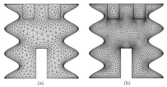
Figure 2.
Sample meshes used for grid study: (a) 2868 elements and (b) 7115 elements.
Then, the following basis expansions were employed for the variables fields,
Then, the residual form of equations was computed by integrating the weak form of equations over a discrete domain:
where the relative index is denoted by the superscript k, subscripts of i, j represent the residual, and node number, respectively. Here, m shows the iteration number. The integrals were performed by second order Gaussian quadrature. The Newton–Raphson iteration algorithm was applied to iteratively solve the residual equations with the following stopping condition for every field variable,
To ensure the independence of the present numerical solution on the grid size of the numerical domain. The results indicate insignificant differences for the 7115 elements grids and above. Therefore, for all computations in this paper for similar problems to this subsection, 7115 elements uniform grid is employed.
For the intention of validating the data, comparisons were performed between the simulated date concerning the current practice and the those recorded by Ilis et al. [47] toward the case of natural convection and entropy generation inside a square cavity among hot sidewalls. Results are illustrated in Figure 3. Moreover, comparisons are reported among the numerical data of the current work and the experimental and numerical works of Paroncini and Corvaro [48] for the free convection within a square form that heated using embedded sources of the bottom and cold sides, as exhibited within Figure 4. Models regarding thermal conductivity and dynamic viscosity are verified by comparison with the experimental data in Figure 5. These outcomes provide confidence in the correctness of the current model and simulations.
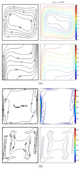
Figure 3.
Comparison of the field patterns with literature work of Ilis et al. [47] (left), current study (right), when and ; (a) the streamlines and isotherm contours and (b) the global entropy generation and Bejan number.
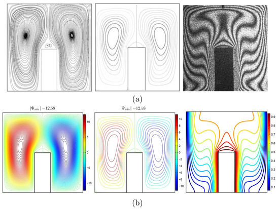
Figure 4.
Paroncini and Corvaro [48] (a) and existing numerical outcome (b); experimental streamlines (left), numerical streamlines (middle), and experimental isotherms (right) at , , , , and .
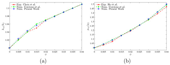
Figure 5.
Comparison of (a) the thermal conductivity ratio with the literature works of Chon et al. [49] and Corcione et al. [50] and (b) the dynamic viscosity ratio with the studies of Ho et al. [51] and Corcione et al. [50].
4. Results and Discussion
Here, segment presents numerical results toward streamlines, isotherms, and nanoparticle distribution concerning seven parameters. These parameters are Rayleigh number and , solid volume fraction of hybrid nanofluid (), and dimensionless heat source length (). The rates of Prandtl number, number of oscillations, amplitude, heat source position, heat source thickness, and thermal conductivity of the solid blocks (brickwork) are fixed at , , , , , and W/m·K, respectively. The values of local and average Nusselt numbers are also determined toward several values and R. The thermophysical properties concerning the base liquid (water), Cu nanoparticles, and AlO nanoparticles phases exist arranged into Table 1.

Table 1.
Thermo-physical properties of water, Cu nanoparticles, and AlO nanoparticles at K [52].
Figure 6 illustrates the streamlines, the isotherms, and the isentropic contours in the cavity toward water and various types of nanofluids, water-Cu, water-AlO, and hybrid water-Cu-AlO. It is clear that the shape of all the contours do not differ greatly when the operating fluid is changed. The streamlines present a symmetry around the isothermal heater. The heater, located through the bottom of the cavity, raises the temperature of the neighboring fluid, which also rises. In contrast, the colder fluid located near the top goes down, and natural convection occurs. As a result, two recirculation zones appear in the cavity, in opposite directions to the right and the left of the heater due to the symmetry of the problem. As for the isothermal contours, they present a plume-like pattern, with concentration zones around the heater walls and the crests of the undulated cavity walls. The hot temperature on the heater walls spreads to a relatively colder region in the cavity center, while the low temperature is constant along the cavity walls. The isentropic contours show concentration zones around the isothermal heater, the crests of the undulated walls and the bottom walls of the two solid blocks. These zones follow the flow patterns and the isothermal contours as they correspond to zones of high heat transfer or strong flow intensity.
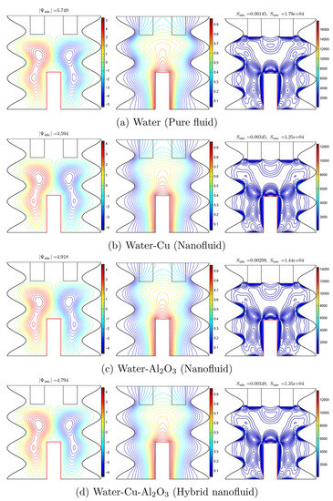
Figure 6.
The streamlines (left), temperature contours (middle), and entropy generation contours (right) for various types of particles when , , and .
The variations of local Nusselt number (Nu) along the length of the isothermal heater W and of the dimensionless temperature along the solid blocks for the various types of particles are shown in Figure 7. It is clear that is lower along the heater wall when water is used compared to the other nanofluids, indicating that adding nanoparticles to water enhances heat transfer. This is due to the higher thermal conductivity of the nanofluids compared to pure water. It is also shown that the hybrid Water-Cu-AlO nanofluid presents the highest among all the fluids, while almost the same values of can be observed when Cu or AlO nanoparticles are used separately. along the solid blocks is maximum when pure water is used, while the minimum value is obtained when the hybrid nanofluid is used. This is related to the heat transfer rate, which is lowest in the case of pure water and thus leading to a higher temperature of the solid blocks.
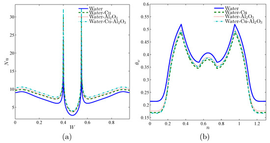
Figure 7.
The evolution of the local characteristic parameters (a) local Nusselt number interfaces with W and (b) local dimensionless temperature on the solid blocks for different types of particles at , , and .
The variations of the average Nusselt number , Bejan number (Be), and the global entropy generation GEG as functions of the volume fraction of the nanoparticles are depicted in Figure 8. First, it is shown that is maximum in the case of the hybrid nanofluid for all the values of . increases when the value of is raised up to 0.01. However, further augmentation of beyond 0.01 has an opposite effect and reduces . Indeed, increasing the volume fraction of the nanoparticles improves the thermal conductivity and heat transfer. This can be seen when is increased up to 0.01. Nonetheless, further increasing also increases the viscosity of the nanofluid as shown in Equation (9). The increase of resistive viscous forces hinders the free convective flow and reduces heat transfer. Therefore, the increase of enhances heat transfer only to some extent. In all cases, the heat transfer enhancement is maximal when the hybrid Water-Cu-AlO is used. It is equally shown that increases with , and it is maximum in the case of Water-Cu nanofluid for all the values of . At the same time, the value of GEG is reduced when is increased and is minimum when Water-Cu nanofluid is used. For all the values of , , meaning that the entropy generation due to fluid friction irreversibility FFI is the dominant part of the GEG compared to the heat transfer irreversibility HTI. As is raised, increases indicating that the share of the HTI in the GEG increases, as the intensity of the flow becomes hindered by the increased viscosity of the nanofluid. For the various values of , is minimum and GEG is maximum in the hybrid nanofluid.
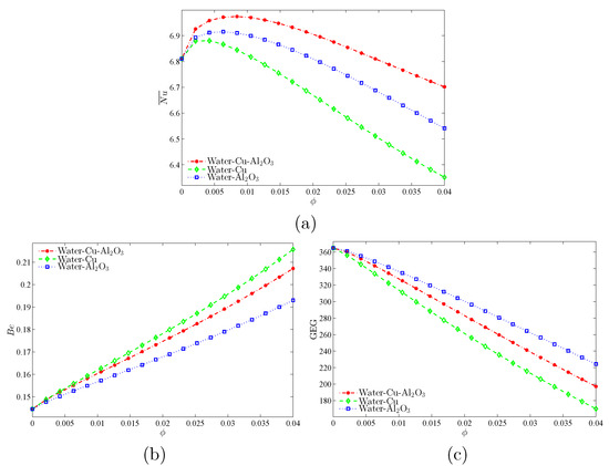
Figure 8.
The evolution of the average characteristic as a function of various volume fractions of nanoparticles for the base fluid, nanofluids and hybrid nanofluids, (a) average Nusselt number (), (b) Bejan number (), and (c) the global entropy generation (GEG) when and .
Figure 9 shows the variations of , , and GEG as functions of Rayleigh number () for the various fluids. remains almost constant even when is varied for . However, when , increases with for all the operating fluids. In fact, indicates the relative importance of the buoyancy forces driving the flow with respect to the viscous forces. A higher value of means a greater intensity of flow and results in an enhancement of the heat transfer. In addition, decreases when is raised for all the fluids, whereas GEG remains constant when and increases beyond that. Indeed, as the flow intensifies for higher , the FFI increases. Simultaneously, the free convection is also enhanced and the GEG. Moreover, it is shown that is higher than 0.5 for low than it decreases to become lower than 0.5 for high , indicating the entropy generation becomes dominant by the FFI instead of the HTI. This transition occurs for comprised between and .
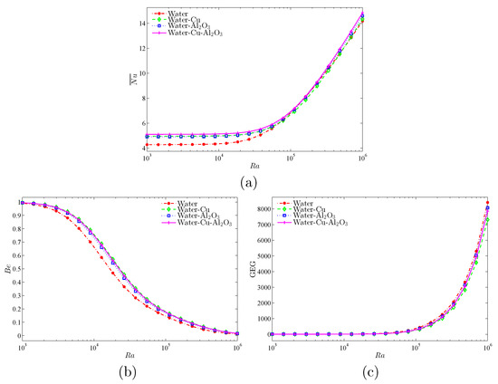
Figure 9.
The evolution of the average characteristic as a function Rayleigh number for the base fluid, nanofluids, and hybrid nanofluids: (a) average Nusselt number (), (b) Bejan number (), and (c) the global entropy generation (GEG) when and .
The variations of , , and GEG as functions of the dimensionless heat source length D are plotted in Figure 10. rises with the increase of D for all the operating fluids. While the range of the heat source does grow, more surrounding fluid is being heated, and the heat transfer is enhanced. increases with D up to due to the rise of the HTI, then remains almost constant after that. The same trend of variation can be observed for GEG.
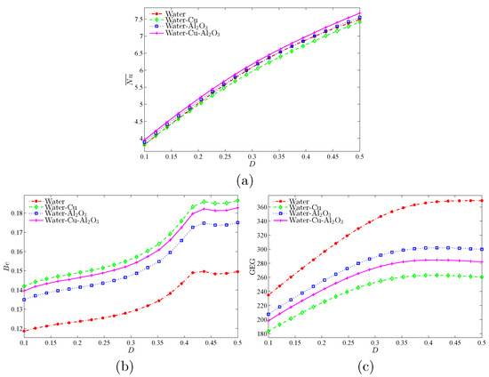
Figure 10.
The evolution of the average characteristic as a function of D for nanofluids and hybrid nanofluids, (a) average Nusselt number (), (b) Bejan number (), and (c) the global entropy generation (GEG) when and .
The effect of on the development of the streamlines, the isotherms and the isentropic contours in the cavity for hybrid nanofluids is illustrated in Figure 11. The streamlines and the isothermal contours are very similar for and . However, the isentropic lines are only limited to the bottom part of the cavity for and start spreading near the top and concentrating on the heater walls when is increased to . Further increasing to has a slight effect on the shape of the flow patterns. Nonetheless, the isotherms change and the contours corresponding to higher temperature move towards the top compared to the cases and , indicating that hot fluid occupies greater surface for . In addition, the isothermal contours become more concentrated near the crests of the undulated cavity walls and the walls of the two solid blocks. Consequently, the concentration zones of the isentropic lines increase in size and cover ore surface inside the cavity. Similar changes can be observed when Ra is increased to . The hot fluid covers more surface in the cavity, and the isentropic lines are concentrated near the walls.
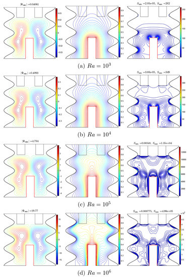
Figure 11.
Evaluation of the streamlines (left), temperature contours (middle), and entropy generation patterns (right) for various Rayleigh numbers for hybrid nanofluids; and .
Figure 12 depicts the variation of local Nusselt Number as a function of W and the variation of the dimensionless temperature on the solid blocks for various values of . It is shown that the on the sidewalls of the heater is greater increases substantially with and is maximum for . Nonetheless, on the upper wall of the heater, decreases when is increased. The average value of increases with as discussed earlier. This means that the rate of heat transfer is not the same over all the heater walls. As seen in the streamlines of Figure 11, the free convective flow creates two recirculation zones to the right and left walls of the heater, while a small separation zone appears above the upper wall. The heat transfer in this zone is lower compared to the side walls. It is also shown that rises along with the solid blocks when is increased, which is due to the fact that the hot fluid is occupying a greater surface in the cavity.

Figure 12.
Evaluation of (a) the local Nusselt number interfaces with W and (b) local dimensionless temperature on the solid blocks with different for hybrid nanofluids; and .
Figure 13 shows the effect of D on the streamlines, the isotherms, and the isentropic contours in the cavity for the various fluids. Raising D increases the volume of the fluid in contact with the heater and, consequently, leads to a more intense convective flow, as indicated by the appearance of additional vortices in the recirculation zones, for instance, when D was increased from 0.3 to 0.4. The shape of the isothermal contours does not vary substantially when D is increased, but the size of the isotherms increases as a larger heater is used. The same can be said for the isentropic contours, which remain concentrated near the heater walls, the crests of the undulated walls, and the bottom walls of the solid blocks.
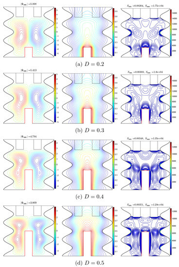
Figure 13.
Evaluation of the streamlines (left), temperature contours (middle), and entropy patterns (right) for various dimensionless heat source lengths (D) in the case of hybrid nanofluids when and .
The variation of local Nusselt Number as a function of W and the variation of the dimensionless temperature on the solid blocks for various values of D is illustrated in Figure 14. The variation of shows the same trend for all the values of D. However, it is shown that along with the isothermal heater, increases when D is reduced. As discussed earlier, the average value of increases for higher D, which means that even if the local is higher in the case of a smaller heater, the overall heat transfer indicated by the average of still increases due to the integration over a larger length. On the other hand, it is shown that the solid blocks have a lower temperature when D is decreased, as the size of the heater is decreased.
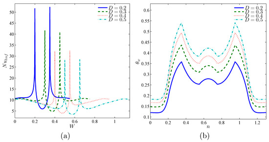
Figure 14.
Evaluation of (a) local Nusselt number interfaces with W and (b) local dimensionless temperature on the solid blocks with different D for hybrid nanofluids; and .
The variations of , , and GEG as functions of toward various values of are plotted in Figure 15. It does show that increases for higher amounts of , which is due, as discussed earlier, to the intensification of the flow when the buoyancy forces dominate the viscous forces. It is also shown that for , increases when is increased, whereas this is not the case when . Indeed, the thermal conductivity and the viscosity both rise with . As the viscous forces are already crucial for low , the increase in the viscosity for higher does not affect the heat transfer, which still improves owing to the rise of the thermal conductivity. Conversely, for high values of , the effect of on the surge of viscosity becomes more apparent and slightly hinders heat transfer. diminishes among the raise of while always being higher when the fraction is increased. This is, respectively, due to the rise of the FFI when the flow is intensified for high and to the reduction of the FFI when the viscosity is increased for higher . GEG remains constant for , then increases with and is also higher when is reduced.
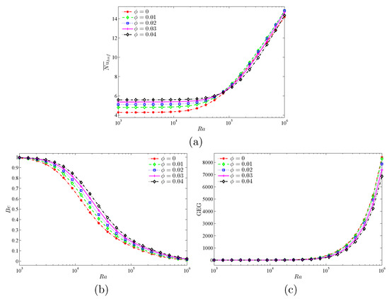
Figure 15.
Evaluation of (a) average Nusselt number (), (b) Bejan number (), and (c) the global entropy generation (GEG) with and different for hybrid nanofluids and .
Figure 16 shows the variations of , and GEG as functions of D for different values of . increases with D. It is maximum when and minimum when or . Increasing D and raises the value of . As the size of the heater is raised, the HTI is increased with respect to the FFI. GEG increases for higher D but is reduced when is increased.
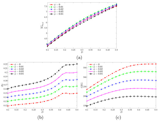
Figure 16.
Evaluation of (a) average Nusselt number (), (b) Bejan number (), and (c) the global entropy generation (GEG) with D and different for hybrid nanofluids and .
Figure 17 reveals the variations of , , and GEG as functions of and for various values of D. Increasing and D increases the amount of the average heat transfer. Increasing reduces while raising GEG. On the other hand, a higher value of D increases and GEG. These observations summarize the effects of and D on the heat transfer and the entropy generation in the cavity. At the same time, indicate that the impact of each parameter is independent of the other.
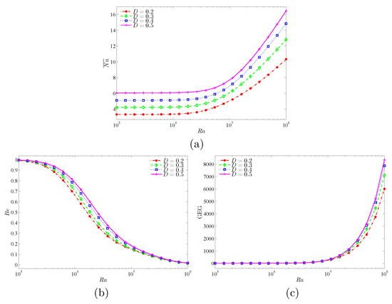
Figure 17.
Evaluation of (a) average Nusselt number (), (b) Bejan number (), and (c) the global entropy generation (GEG) with and different D for hybrid nanofluids and .
5. Conclusions
The conjugate free convection flow, heat transfer, and entropy generation of copper–alumina/water hybrid nanofluids were investigated inside a partially divided cavity. The sidewalls of the cavity were wavy and cold. The non-dimensional form of the governing equations was solved using the FEM. The FEM code was verified by comparing the results of the code and the literature data. The grid study was also produced for assuring the accuracy of the computations. The influence of using copper/water, alumina/water nanofluids, and copper/alumina hybrid nanofluids on the isotherms, streamlines, and entropy generation patterns, as well as the heat transfer and entropy generation characteristics, were addressed. The outcomes of the existing numerical research can be summarized as follows.
- The heat transfer occurs greater in nanofluids contrasted to pure water, and it is maximum in the case of Water–Cu–AlO hybrid nanofluid. Improving the volumetric flow rate of of the nanoparticles enhances heat transfer due to the higher resulting thermal conductivity. This is valid for . Above this value, the increase in slightly hinders heat transfer due to the increased viscosity concerning the fluid.
- Increasing improves heat transfer due to the developed importance regarding the driving buoyancy forces compared to the resistive viscous forces.
- Using a smaller heater by reducing D hinders heat transfer as less surrounding fluid is being heated.
- The global entropy generation GEG rises with the increase of and D but decreases when a higher value of is used. Due to the variations in the flow intensity and the fluid viscosity with the different parameters, the flow patterns and the isothermal contours in the cavity vary and affect the source of the entropy generation. The FFI dominates entropy generation when is raised, while the effect of the HTI increases when higher values of and D are used.
Author Contributions
Conceptualization, A.I.A. and M.G.; methodology, A.I.A.; software, A.I.A., M.G. and A.H.; validation, A.I.A.; formal analysis, A.H., A.I.A., M.S.P.; investigation, A.I.A., M.G., M.S.P., A.H. and S.N.; resources, I.H. and S.N.; write draft preparation, A.I.A., I.H., A.H., M.G., S.N., and M.S.P.; write and editing, A.I.A., I.H., A.H., M.G., S.N., and M.S.P.; visualization, A.I.A. and M.G.; supervision, I.H. and S.N. All authors have read and agreed to the published version of the manuscript.
Funding
We are grateful for the financial support received from the Malaysian Ministry of Education under the research grant FRGS/1/2019/STG06/UKM/01/2.
Acknowledgments
We thank the respected reviewers for their constructive comments which clearly enhanced the quality of the manuscript.
Conflicts of Interest
The authors declare no conflicts of interest.
References
- Singh, H.; Eames, P.C. Correlations for natural convective heat exchange in CPC solar collector cavities determined from experimental measurements. Sol. Energy 2012, 86, 2443–2457. [Google Scholar] [CrossRef]
- Laguerre, O.; Amara, S.B.; Flick, D. Experimental study of heat transfer by natural convection in a closed cavity: Application in a domestic refrigerator. J. Food Eng. 2005, 70, 523–537. [Google Scholar] [CrossRef]
- El Omari, K.; Kousksou, T.; Le Guer, Y. Impact of shape of container on natural convection and melting inside enclosures used for passive cooling of electronic devices. Appl. Therm. Eng. 2011, 31, 3022–3035. [Google Scholar] [CrossRef]
- Marandi, O.F.; Ameri, M.; Adelshahian, B. The experimental investigation of a hybrid photovoltaic-thermoelectric power generator solar cavity-receiver. Sol. Energy 2018, 161, 38–46. [Google Scholar] [CrossRef]
- Choi, S.U.S.; Eastman, J.A. Enhancing Thermal Conductivity of Fluids with Nanoparticles; Technical Report; Argonne National Lab.: Lemont, IL, USA, 1995. [Google Scholar]
- Izadi, S.; Armaghani, T.; Ghasemiasl, R.; Chamkha, A.J.; Molana, M. A comprehensive review on mixed convection of nanofluids in various shapes of enclosures. Powder Technol. 2019, 343, 880–907. [Google Scholar] [CrossRef]
- Khanafer, K.; Vafai, K.; Lightstone, M. Buoyancy-driven heat transfer enhancement in a two-dimensional enclosure utilizing nanofluids. Int. J. Heat Mass Transf. 2003, 46, 3639–3653. [Google Scholar] [CrossRef]
- Jou, R.Y.; Tzeng, S.C. Numerical research of nature convective heat transfer enhancement filled with nanofluids in rectangular enclosures. Int. Commun. Heat Mass Transf. 2006, 33, 727–736. [Google Scholar] [CrossRef]
- Kakaç, S.; Pramuanjaroenkij, A. Review of convective heat transfer enhancement with nanofluids. Int. J. Heat Mass Transf. 2009, 52, 3187–3196. [Google Scholar] [CrossRef]
- Basak, T.; Chamkha, A.J. Heatline analysis on natural convection for nanofluids confined within square cavities with various thermal boundary conditions. Int. J. Heat Mass Transf. 2012, 55, 5526–5543. [Google Scholar] [CrossRef]
- Bondareva, N.S.; Sheremet, M.A. Effect of Nano-Sized Heat Transfer Enhancers on PCM-Based Heat Sink Performance at Various Heat Loads. Nanomaterials 2020, 10, 17. [Google Scholar] [CrossRef] [PubMed]
- Izadi, M.; Sheremet, M.A.; Mehryan, S.A.M.; Pop, I.; Öztop, H.F.; Abu-Hamdeh, N. MHD thermogravitational convection and thermal radiation of a micropolar nanoliquid in a porous chamber. Int. Commun. Heat Mass Transf. 2020, 110, 104409. [Google Scholar] [CrossRef]
- Izadi, M.; Mohammadi, S.A.; Mehryan, S.A.M.; Yang, T.; Sheremet, M.A. Thermogravitational convection of magnetic micropolar nanofluid with coupling between energy and angular momentum equations. Int. J. Heat Mass Transf. 2019, 145, 118748. [Google Scholar] [CrossRef]
- Sheremet, M.; Grosan, T.; Pop, I. MHD free convection flow in an inclined square cavity filled with both nanofluids and gyrotactic microorganisms. Int. J. Numer. Methods Heat Fluid Flow 2019, 29, 4642–4659. [Google Scholar] [CrossRef]
- Izadi, M.; Oztop, H.F.; Sheremet, M.A.; Mehryan, S.A.M.; Abu-Hamdeh, N. Coupled FHD–MHD free convection of a hybrid nanoliquid in an inversed T-shaped enclosure occupied by partitioned porous media. Numer. Heat Transf. Part A Appl. 2019, 76, 479–498. [Google Scholar] [CrossRef]
- Sivasankaran, S.; Alsabery, A.I.; Hashim, I. Internal heat generation effect on transient natural convection in a nanofluid-saturated local thermal non-equilibrium porous inclined cavity. Phys. A Stat. Mech. Its Appl. 2018, 509, 275–293. [Google Scholar] [CrossRef]
- Astanina, M.S.; Sheremet, M.; Umavathi, C.J. Unsteady natural convection in a partially porous cavity having a heat-generating source using local thermal non-equilibrium model. Int. J. Numer. Methods Heat Fluid Flow 2019, 29, 1902–1919. [Google Scholar] [CrossRef]
- Alsabery, A.I.; Siddheshwar, P.G.; Saleh, H.; Hashim, I. Transient free convective heat transfer in nanoliquid-saturated porous square cavity with a concentric solid insert and sinusoidal boundary condition. Superlattices Microstruct. 2016, 100, 1006–1028. [Google Scholar] [CrossRef]
- Asl, A.K.; Hossainpour, S.; Rashidi, M.M.; Sheremet, M.A.; Yang, Z. Comprehensive investigation of solid and porous fins influence on natural convection in an inclined rectangular enclosure. Int. J. Heat Mass Transf. 2019, 133, 729–744. [Google Scholar]
- Hoseinzadeh, S.; Sahebi, S.A.R.; Ghasemiasl, R.; Majidian, A.R. Experimental analysis to improving thermosyphon (TPCT) thermal efficiency using nanoparticles/based fluids (water). Eur. Phys. J. Plus 2017, 132, 197. [Google Scholar] [CrossRef]
- Alsabery, A.I.; Ismael, M.A.; Chamkha, A.J.; Hashim, I. Numerical investigation of mixed convection and entropy generation in a wavy-walled cavity filled with nanofluid and involving a rotating cylinder. Entropy 2018, 20, 664. [Google Scholar] [CrossRef]
- Hoseinzadeh, S.; Heyns, P.S.; Kariman, H. Numerical investigation of heat transfer of laminar and turbulent pulsating Al2O3/water nanofluid flow. Int. J. Numer. Methods Heat Fluid Flow 2019, 30, 1149–1166. [Google Scholar] [CrossRef]
- Alsabery, A.I.; Armaghani, T.; Chamkha, A.J.; Hashim, I. Conjugate heat transfer of Al2O3-water nanofluid in a square cavity heated by a triangular thick wall using Buongiorno’s two-phase model. J. Therm. Anal. Calorim. 2019, 135, 161–176. [Google Scholar] [CrossRef]
- Ghasemiasl, R.; Hoseinzadeh, S.; Javadi, M.A. Numerical analysis of energy storage systems using two phase-change materials with nanoparticles. J. Thermophys. Heat Transf. 2018, 32, 440–448. [Google Scholar] [CrossRef]
- Mahdi, J.M.; Mohammed, H.I.; Hashim, E.T.; Talebizadehsardari, P.; Nsofor, E.C. Solidification enhancement with multiple PCMs, cascaded metal foam and nanoparticles in the shell-and-tube energy storage system. Appl. Energy 2020, 257, 113993. [Google Scholar] [CrossRef]
- Ahmad, S.; Nadeem, S.; Ullah, N. Entropy generation and temperature-dependent viscosity in the study of SWCNT–MWCNT hybrid nanofluid. Appl. Nanosci. 2020. [Google Scholar] [CrossRef]
- Ahmad, S.; Nadeem, S.; Muhammad, N.; Issakhov, A. Radiative SWCNT and MWCNT nanofluid flow of Falkner–Skan problem with double stratification. Phys. A Stat. Mech. Its Appl. 2020, 547, 124054. [Google Scholar] [CrossRef]
- Abbas, N.; Nadeem, S.; Malik, M. Theoretical study of micropolar hybrid nanofluid over Riga channel with slip conditions. Phys. A Stat. Mech. Its Appl. 2020, 551, 124083. [Google Scholar] [CrossRef]
- Shahsavar, A.; Sardari, P.T.; Toghraie, D. Free convection heat transfer and entropy generation analysis of water-Fe3O4/CNT hybrid nanofluid in a concentric annulus. Int. J. Numer. Methods Heat Fluid Flow 2019, 29, 915–934. [Google Scholar] [CrossRef]
- Shahsavar, A.; Godini, A.; Sardari, P.T.; Toghraie, D.; Salehipour, H. Impact of variable fluid properties on forced convection of Fe3O4/CNT/water hybrid nanofluid in a double-pipe mini-channel heat exchanger. J. Therm. Anal. Calorim. 2019, 137, 1031–1043. [Google Scholar] [CrossRef]
- Nadeem, S.; Abbas, N.; Malik, M.Y. Inspection of hybrid based nanofluid flow over a curved surface. Comput. Methods Progr. Biomed. 2020, 189, 105193. [Google Scholar] [CrossRef]
- Khan, M.R.; Pan, K.; Khan, A.U.; Nadeem, S. Dual solutions for mixed convection flow of SiO2–Al2O3/water, hybrid nanofluid near the stagnation point flow over a curved surface. Phys. A Stat. Mech. Its Appl. 2020, 547, 123959. [Google Scholar] [CrossRef]
- Sheikholeslami, M.; Mehryan, S.A.M.; Shafee, A.; Sheremet, M.A. Variable magnetic forces impact on magnetizable hybrid nanofluid heat transfer through a circular cavity. J. Mol. Liq. 2019, 277, 388–396. [Google Scholar] [CrossRef]
- Chamkha, A.; Ismael, M.; Kasaeipoor, A.; Armaghani, T. Entropy generation and natural convection of CuO-water nanofluid in C-shaped cavity under magnetic field. Entropy 2016, 18, 50. [Google Scholar] [CrossRef]
- Ghalib, H.S.; Ismael, M.A. Heat and Mass Transfer in Partially-Layered Cavity with Inner Square conductive Body. Int. J. Therm. Environ. Eng. 2016, 13, 67–74. [Google Scholar]
- Ismael, M.A.; AL-Mayahi, H.A.; Jawad, I.N. Natural Convection Heat Transfer in Arc Shape Wall Porous Cavity Filled with Nano-Fluid. Basrah J. Eng. Sci. 2014, 14, 137–148. [Google Scholar]
- Dogonchi, A.S.; Selimefendigil, F.; Ganji, D.D. Magneto-hydrodynamic natural convection of CuO-water nanofluid in complex shaped enclosure considering various nanoparticle shapes. Int. J. Numer. Methods Heat Fluid Flow 2019, 29, 1663–1679. [Google Scholar] [CrossRef]
- Selimefendigil, F.; Öztop, H.F. Control of natural convection in a CNT-water nanofluid filled 3D cavity by using an inner T-shaped obstacle and thermoelectric cooler. Int. J. Mech. Sci. 2020, 169, 105104. [Google Scholar] [CrossRef]
- Oliveski, R.D.C.; Macagnan, M.H.; Copetti, J.B. Entropy generation and natural convection in rectangular cavities. Appl. Therm. Eng. 2009, 29, 1417–1425. [Google Scholar] [CrossRef]
- Alsabery, A.I.; Tayebi, T.; Chamkha, A.J.; Hashim, I. Effect of rotating solid cylinder on entropy generation and convective heat transfer in a wavy porous cavity heated from below. Int. Commun. Heat Mass Transf. 2018, 95, 197–209. [Google Scholar] [CrossRef]
- Sivaraj, C.; Sheremet, M.A. MHD natural convection and entropy generation of ferrofluids in a cavity with a non-uniformly heated horizontal plate. Int. J. Mech. Sci. 2018, 149, 326–337. [Google Scholar] [CrossRef]
- Liu, W.; Shahsavar, A.; Barzinjy, A.A.; Al-Rashed, A.A.A.A.; Afrand, M. Natural convection and entropy generation of a nanofluid in two connected inclined triangular enclosures under magnetic field effects. Int. Commun. Heat Mass Transf. 2019, 108, 104309. [Google Scholar] [CrossRef]
- Selimefendigil, F.; Öztop, H.F. Effects of conductive curved partition and magnetic field on natural convection and entropy generation in an inclined cavity filled with nanofluid. Phys. A Stat. Mech. Its Appl. 2020, 540, 123004. [Google Scholar] [CrossRef]
- Tayebi, T.; Öztop, H.F. Entropy production during natural convection of hybrid nanofluid in an annular passage between horizontal confocal elliptic cylinders. Int. J. Mech. Sci. 2020, 171, 105378. [Google Scholar] [CrossRef]
- Tayebi, T.; Chamkha, A.J. Entropy generation analysis during MHD natural convection flow of hybrid nanofluid in a square cavity containing a corrugated conducting block. Int. J. Numer. Methods Heat Fluid Flow 2019, 30, 1115–1136. [Google Scholar] [CrossRef]
- Corcione, M. Empirical correlating equations for predicting the effective thermal conductivity and dynamic viscosity of nanofluids. Energy Convers. Manag. 2011, 52, 789–793. [Google Scholar] [CrossRef]
- Ilis, G.G.; Mobedi, M.; Sunden, B. Effect of aspect ratio on entropy generation in a rectangular cavity with differentially heated vertical walls. Int. Commun. Heat Mass Transf. 2008, 35, 696–703. [Google Scholar] [CrossRef]
- Paroncini, M.; Corvaro, F. Natural convection in a square enclosure with a hot source. Int. J. Therm. Sci. 2009, 48, 1683–1695. [Google Scholar] [CrossRef]
- Chon, C.H.; Kihm, K.D.; Lee, S.P.; Choi, S.U. Empirical correlation finding the role of temperature and particle size for nanofluid (Al2O3) thermal conductivity enhancement. Appl. Phys. Lett. 2005, 87, 3107. [Google Scholar] [CrossRef]
- Corcione, M.; Cianfrini, M.; Quintino, A. Two-phase mixture modeling of natural convection of nanofluids with temperature-dependent properties. Int. J. Therm. Sci. 2013, 71, 182–195. [Google Scholar] [CrossRef]
- Ho, C.; Liu, W.; Chang, Y.; Lin, C. Natural convection heat transfer of alumina-water nanofluid in vertical square enclosures: An experimental study. Int. J. Therm. Sci. 2010, 49, 1345–1353. [Google Scholar] [CrossRef]
- Bergman, T.L.; Incropera, F.P. Introduction to Heat Transfer, 6th ed.; Wiley: New York, NY, USA, 2011. [Google Scholar]


© 2020 by the authors. Licensee MDPI, Basel, Switzerland. This article is an open access article distributed under the terms and conditions of the Creative Commons Attribution (CC BY) license (http://creativecommons.org/licenses/by/4.0/).