Review

Integral PWR-Type Small Modular Reactor Developmental Status, Design Characteristics and Passive Features: A Review

Faculty of Energy Systems and Nuclear Science, University of Ontario Institute of Technology, Oshawa, ON L1H 7K4, Canada
*
Author to whom correspondence should be addressed.
Energies 2020, 13(11), 2898; https://doi.org/10.3390/en13112898
Submission received: 5 March 2020 / Revised: 3 April 2020 / Accepted: 1 June 2020 / Published: 5 June 2020
(This article belongs to the Section K: State-of-the-Art Energy Related Technologies)

Abstract

:
In recent years, the trend in small modular reactor (SMR) technology development has been towards the water-cooled integral pressurized water reactor (iPWR) type. The innovative and unique characteristics of iPWR-type SMRs provide an enhanced safety margin, and thus offer the potential to expand the use of safe, clean, and reliable nuclear energy to a broad range of energy applications. Currently in the world, there are about eleven (11) iPWR-type SMRs concepts and designs that are in various phases of development: under construction, licensed or in the licensing review process, the development phase, and conceptual design phase. Lack of national and/or internatonal comparative framework for safety in SMR design, as well as the proprietary nature of designs introduces non-uniformity and uncertainties in regulatory review. That said, the major primary reactor coolant system components, such as the steam generator (SG), pressurizer (PRZ), and control rod drive mechanism (CRDM) are integrated within the reactor pressure vessel (RPV) to inherently eliminate or minimize potential accident initiators, such as LB-loss of coolant accidents (LOCAs). This paper presents the design status, innovative features and characteristics of iPWR-type SMRs. We delineate the common technology trends, and highlight the key features of each design. These reactor concepts exploit natural physical laws such as gravity to achieve the safety functions with high level of margin and reliability. In fact, many SMR designs employ passive safety systems (PSS) to meet the evolving stringent regulatory requirements, and the extended consideration for severe accidents. A generic classification of PSS is provided. We constrain our discussion to the decay heat removal system, safety injection system, reactor depressurization system, and containment system. A review and comparative assessment of these passive features in each iPWR-type SMR design is considered, and we underline how it maybe more advantageous to employ passive systems in SMRs in contrast to conventional reactor designs.

Graphical Abstract

1. Introduction

The pursuit of the development and deployment of small modular reactors (SMRs) is a persistent and global phenomenon with widespread interest from technology developers, Research and Development (R&D) organizations and potential users. Motivations in the development of SMR technology inlcudes: meeting the need for flexible power generation for wider range of users and applications; siting flexibility; options for remote and off-grid application; inherent and enhanced safety features; and the potential for synergetic energy systems. The International Atomic Energy Agency (IAEA) defines small modular reactors as, “advanced nuclear reactors that produce equivalent electric power of up to 300 MW(e), and are designed to be built in factories and transportable to utilities for installation as demand arises” [1,2]. Many SMRs are envisioned for use in niche electricity or energy markets where large nuclear power plants are not feasible, including smaller grid and footprint applications, replacement of retiring fossil fuel plants, and industrial process heat applications such as desalination and hydrogen production [3,4]. Thus, SMRs offer the potential to expand the use of safe, peaceful, and reliable nuclear energy to a broad range of customers and energy applications. This, in turn, can significantly contribute to a carbon free world, provide a viable option to address climate change, and may serve as an appropraite option in addressing Sustainable Development Goal 7, i.e., providing affordable and clean energy [5].
Despite its advantages and significant advancements made in the recent years, some technical issues still impede and challenge the future deployment of SMRs, and thus requiring considerable attention within the SMR community. Figure 1 provides an average ranking of identified challenges/issues for SMR design development and deployment; and we underline that passive safety systems (PSSs) is ranked as the second most important impediment [1]. In fact, this paper is motivated by the results presented in Figure 1. A generic overview, an explanantion of the need for this technology, and broad classification of PSSs based on class, operating mechanism, and functions, are provided.
In recent years, the trend in SMR technology development is toward iPWR-type SMRs, which integrates the major primary system components to inherently eliminate or minimize potential accident initiators, and employ simplified PSSs to counter and mitigate the remaining accident initiators. The integrated reactor coolant system (IRCS) is arguably the key feature that distinguish iPWR-type SMR from large reactor designs, besides other features including the integrated control rod drive mechanism and multi-module deployment. Currently in the world there are about eleven (11) iPWR-type SMR designs and concepts globally [6], with most of them in developmental stages, and some planned for near-term deployment. We focus our discussion on iPWR-type SMR designs as they share a common set of design principles to enhance plant safety, despite a number of design differences. One of the common trends is the implementation of a simplified PSSs that relies on natural physical laws to achieve the required safety functions under normal as well as accident scenarios. This eliminates the need for external energy source, eliminate/minimize reliance on operator actions, and thus provide a robust barrier to cope with accidents such as station black-outs. Additionally, the vulnerability of safety system failure due to component failures and human error is minimized considerably, which in turn reduces the predicted core damage frequency. The IAEA reported that there has been a strong tendency from the vendors and R&D organizations to employ PSSs in SMRs [7], which could potentially improve and increase the safety margin utilizing natural laws. We note that passive features such as the passive residual heat removal system (PRHRS) have been implemented, or at least conceptualized in many conventional GenIII+ reactor designs, such as AP1000 [8] and ESBWR [9]. This paper focuses on the implemention of four (4) key PSSs in iPWR-type SMRs designs. The structure of the paper is as follows. Section 2 provides an overview of current iPWR-type SMRs, including technology developers, design status, and characteristics, with unique and novel features of each design. Section 3 presents the need for passive features in advanced reactors, and categorize PSSs based on class, operating mechanism and functions. Note that the discussion of PSSs is contained to the passive residual heat removal system (PRHRS), passive safety injection system (PSIS), passive depressurization system (PDS) and passive containment cooling system (PCCS). Section 4 presents a comparative assessment of the four (4) PSSs in iPWR-type SMRs. Section 5 presents open issues and technical challenges related to generic PSSs, and within the context of iPWR-type SMRs. Section 6 presents the conclusion and recommendations.

2. iPWR-Type Small Modular Reactor Designs

Although non-water cooled SMRs, such as the molten salt type, are proposed, water-cooled modular designs hold historical significance. This is largely due to the initially selected designs, supported by fuel and components manufactures. Subsequently, most of the 60+ years of operating experience, technical lessons learned, including those from major accidents have been water-cooled reactors. major accidents. Table 1 presents the current iPWR designs under different phases of development. The iPWR design characteristics offers the potential to: (a) eliminate some potential accidents initiators (e.g., large loss of coolant accidents (LOCAs), control rod ejection accident); (b) decrease the probability of failure for remaining initiators; and, (c) enhanced features to mitigate the consequences [4,10,11,12,13]. These classes of SMRs follow the ‘safety-in-design’ philosophy with the objectives to inherently eliminate or minimize potential accident initiators, and to mitigate/counteract the remaining initiators within the design limits by simplified and reliable passive systems. These objectives are realized by integrating the major reactor coolant system components within a reactor pressure vessel, such as steam generators, pressurizer, and control rod drive mechanism. The influence of the IRCS approach on the existing general design criteria, defense-in-depth philosophy, and regulatory requirements can be found in [14] and surmised from the design certification application of the NuScale Power SMR to the U.S. Nuclear Regulatory Commission (NRC [15]. We present in Table 2 a concise summary of the design characteristics, unique features and deployment strategy of each iPWR-type SMR designs. In the work by Mi et al. [16], we provide a brief technical description of each of the iPWR SMR reactor designs.

2.1. ACP100

The ACP100 is an innovative multipurpose reactor design based on existing PWR technology that adapts an integrated Reactor Coolant System (RCS) design and advanced passive safety features. ACP100 is being developed by the China National Nuclear Corporation (CNNC) with an electric power of 100 MW(e) per module, with an option to increase up to eight (8) modules as demand arises. Besides electricity generation, ACP100 is also intended for cogeneration purposes, such as desalination, heating, and steam production. The integrated steam supply system installed within the RPV consists of the reactor core, sixteen (16) once-through steam generators (SGs), and a pressurizer (PRZ) [11]. The ACP100 reactor core consists of 57 fuel assemblies in a 17 × 17 square pitch configuration with a total length of 2.15 m, and an expected UO2 enrichment of about 2.4–4.0% [17]. Solid burnable poison, soluble boron, and 25 control rods are used to control the reactivity. The primary cooling mechanism of the ACP100 under normal operating and shutdown conditions is achieved by means of forced circulation with four (4) dedicated pumps. The ACP100’s passive systems mainly consists of a passive decay heat removal system (PDHRS), passive safety injection system (PSIS), passive containment heat removal system, and reactor de-pressurization system (RDPS) [18]. The distinguishing features of the ACP100 includes integrated tube-in-tube once through steam generator, underground nuclear island and large coolant inventory per MW(th). An industrial twin unit demonstration plant with a capacity of 310 MW(th) per unit is planned in Fujian Province, China [19]. A feasibility study shows that the ACP100 may cost approximately 5000 USD $/kW, and is expected to be economically competitive against large NPPs if more than four (4) modules are built at the same time.
Table 2. Design characteristics of iPWR-type SMRs [18]. Reproduced from [18], IAEA: 2018.
iPWR DesignsCAREMSMARTNuScaleACP100mPowerCAP150IRISIMRW-SMRVBER-300RITM-200
Major primary system component integration
SGs YesYesYesYesYesYesYesYesYesYes Yes
PressurizerYesYesYesNo YesYesYesYes YesNo No
CRDMsYesNoNoNoYesYesYesYesYesYes No
Key design characteristics
Approach to ESFsPassivePassive Passive PassivePassive Passive Passive Hybrid Passive HybridHybrid
PCCMNCFCNCFCFCFCFCNCFCFCFC
MW(th)10036516038557545010001000800917175
MW(e)311005012519515033535022532550
Predicted CDF (/ry) 10 7 2 × 10 7 < 10 8 < 10 6 10 8 < 10 7 10 8 3 × 10 7 < 10 8 10 6 10 6
Modules per plant 1 1 ( 1 12 ) ( 1 8 ) 2 2 ( 1 4 ) 1 1 1 2
Design life (years)6060606060806060606060
TCD (months)36363636353636 < 42 < 24 4048
CCPossibleYesPossible Possible Possible Possible Possible YesPossible YesYes
Note: Hybrid: (active + passive). SGs: steam generators; CRDMs: control rod drive mechanisms; ESFs: engineered safety features; PCCM: primary coolant circulation mechanism; NC: natural circulation; FC: forced circulation; CDF: core damage frequency; TCD: target construction duration; CC: cogeneration capabilities.

2.2. CAP150

The CAP150, with a capacity of 150 MW(e), was designed by Shanghai Nuclear Engineering Research and Design Institute (SNERDI), primarily developed for generation and supply of electricity to remote regions, district heating, and to replace the retiring thermal power plants. The design integrates the major primary system components including eight (8) SGs, reactor coolant pumps (RCPs), Pressurizer (PZR), and control rod drive mechanism (CRDM) within the reactor pressure vessel (RPV). This design approach minimizes the RPV penetration and eliminates postulated accident scenarios, such as large break–loss of coolant accident (LB-LOCA), rod ejection accident, and also reduce the scope of small break–loss of coolant accident (SB-LOCA) [20]. The reactor core consists of 69 fuel assemblies in a 15 × 15 array with the UO2 pellet enriched up to an average of 4.5%. The reactivity control in CAP150 is solely achieved by employing control rods connected with electromagnetic CRDMs. This eliminates soluble boron from the core, and thus avoids boron dilution accidents and provide a better negative reactivity coefficient. A high level of safety is assured by the sensible combination of passive and active engineered safety systems together with severe accident mitigation features. Passive safety systems in CAP150 include the passive decay heat removal system by the primary, as well as secondary, SG side, simplified PSIS, and passive containment cooling system. Due to the novel and peculiar design safety approach, it is claimed that only low pressure injection is needed to maintain core uncovery. The key features of CAP150 include a submerged containment in reactor pool, a design life of 80 years, low core power density, and a flexible load following capability [6]. In 2013, State Nuclear Power Technology Corporation (SNPTC) quoted approximately $5000/kW capital cost and 9 c/kWh [21].

2.3. CAREM25

Central Argentina de Elementos Modulares (CAREM25) is Argentina’s national SMR development project with the goals to locally develop, design, and construct advanced small water cooled reactors with a high level of safety for electricity generation purposes. CAREM25 is a prototype plant based on an indirect steam cycle with a capacity of 31 MW(e) intended to serve as the basis for future commercial CAREM that will generate a capacity of 150 MW(e) [6]. Some distinctive design characteristics of CAREM includes integrated mini-helical vertical SGs (12 numbers) and in-vessel hydraulic control rod drive mechanisms within an RPV of 11 meters, natural circulation (NC) primary cooling mechanism, and self-pressurization eliminating conventional pressurizer heater [22]. Additionally, to cope with extreme natural hazards, a station black-out scenario in CAREM25 is intrinsically included into the design basis [23]. The reactor core comprises 61 fuel assemblies of hexagonal cross section fuel with an enrichment of (1.8–3.1)% UO2. The reactivity is cotrolled by means of burnable poison (Gd2O3) and movable absorbing rods (Ag-In-Cd alloy), thus yielding a boron free core [24]. The applied defense-indepth concept is based on the Western European Nuclear Regulators Association (WENRA) proposal, which includes multiple failure events, independence between Defense-in-Depth (DiD) levels, and consideration of beyond design basis accidents. The safety systems of CAREM25 consists of two (2) reactor protection systems (RPS), two (2) shutdown systems with one driven by hydraulic control rods and the other by gravity injection, two (2) passive residual heat removal systems (PRHRSs), reactor depressurization valves, two (2) low pressure passive injection systems, and a supression pool type containment system. The availability of one PRHRS ensures a grace period of 36 h, in which fundamental safety functions are accomplished without requiring any operator action or electrical power [25].

2.4. IMR

The Integrated Modular Water Reactor (IMR) is an integral pressurized water reactor with a capacity of 1000 MW(th) intended for cogeneration of electricity, district heating, sea water desalination, and process steam production. IMR employs a naturally circulated primary cooling mechanism and adopts a self-pressurization system, thus eliminating the need for primary coolant pumps and pressurizer. The RPV contains the reactor core and internal structures, SGs, CRDMs, and a riser. The reactor core consists of 97 fuel assemblies in a 21 × 21 array with 4.95% average enrichment using U-235 [26]. Reactivity is controlled by means of control and absorber rods with diverse CRDMs, i.e., motor and hydraulic driven types, supplemented with a soluble boron system to backup reactor shutdown. IMR employs a stand-alone direct heat removal system (SDHS) as part of the hybrid heat transport system, utilizing two types of SGs located in the upper (vapour portion) and lower region (liquid portion) of the RPV respectively. Two trains of SDHS are used to provide redundancy, and decay heat is removed by water-cooling in the early stages of an accident, and then air-cooling is achieved at a later stage [20]. The design features of IMR eliminate the need for Emergency Core Cooling System (ECCS), injection systems, and containment cooling/spray systems. The IMR reactor control system is designed for a 100% load rejection capability, and enables a flexible load, followed by controlling the feedwater flowrate and control rods, without causing a reactor trip [25].

2.5. IRIS

The International Reactor Innovative and Secure (IRIS) is being developed by an international group of organizations with the main objectives to systematically sought synergism between safety and economics, eliminate accident initiators rather than coping with the consequences, and to provide an enhanced safety and reliability [10]. In IRIS, these objectives are achieved through the “safety-by-design” approach. Designed with a capacity of 1000 MW(th), the modular IRIS is intended for electricity generation, heat production, seawater desalination, and synergetic energy system applications (coupling with renewable energy) [27]. IRIS adopts proven light water reactor (LWR) technology with simplified safety features poineered by Westinghouse in the AP600 and AP1000 plants. The reactor core consists of 89 fuel assemblies each consisting 264 fuel rods in a 17 × 17 array based on conventional UO2 fuel enriched up to 4.95%. The core is designed for a 3–3.5 years cycle, to optimize the overall fuel and maximize the discharge burnup [28]. Reactivity control is achieved by means of solid burnable absorbers, control rods, and soluble boron in the reactor coolant. The in-vessel CRDMs eliminates uncontrolled rod ejection accident, and all operational issues are related to corrosion cracking of the nozzle welds and seals. The eight (8) IRIS SGs are once-through, with a helical coil tube bundle design, with the tubes and headers designed at full external RCS pressure. The IRIS pressurizer is integrated into the upper head of the reactor vessel, and has a total volume of about 71 cubic meters, which includes a steam volume of 49 cubic meters. IRIS passive safety features consist of a passive emergency heat removal system (EHRS) with four (4) independent trains inmmersed in a refueling water storage tank, two (2) compact full-system pressure emergency boration tanks, a small Automatic Depressurization System (ADS) from the pressurizer steam space, and a containment pressure suppression system consisting of six (6) water tanks and a common tank for non-condensable gas storage. The heat sink is designed to remove the decay heat for seven (7) days without operator action or off-site assistance for replenishing [27]. The overnight capital cost is estimated to be $5000/kW [5].

2.6. mPower

The mPower is an advanced iPWR SMR with a rated power output of 575 MW(th) per module, designed to be fully shop-manufactured, shippable by rail/truck and installed into the facility. The standard plant design consist of two (2) mPower modules to generate power of 390 MW(e) for electricity generation. The design incorporates inherent and passive safety features, proven technology with simpler, smaller, and fewer components [29]. The nuclear steam supply system components, including the reactor core, SGs, pressurizer, and CRDMs, are installed within a single RPV, and the remaining small penetrations are placed well above the core. This approach eliminates large break LOCA, maximizes the reactor coolant inventory, ensures that the reactor core remains covered by coolant during a small LOCA, and eliminates the possibility of rod ejection accidents [30]. The reactor core consists of 69 fuel assemblies (FAs) in 17 × 17 array with a shortened active length of 2.4 m, and the U-235 fuel rods enriched below 5% [20]. Reactivity control is achieved through the electro-mechanical actuation of Ag In-Cd control rods, and use of the strong negative moderator temperature coefficient by control of the secondary side feedwater flow rates. Note that soluble boron is eliminated from the reactor coolant for reactivity control thus excluding the possibility of inadvertent reactivity insertion as a result of boron dilution. The mPower deploys a decay heat removal strategy with an auxiliary steam condenser on the secondary system, water injection, or cavity flooding using the refueling water storage tank and passive containment cooling. The mPower-engineered safety features consist of two DHRS, two ECCS, two automatic depressurization systems (ADSs), and one PCCS. Key distinuishing features of the design includes low linear heat rate, undergound RPV, minimum of 7 to 14 days cooling without AC power or operation action, and enhanced underground spent fuel pool with a large heat sink to provide up to 30 days cooling [31].

2.7. NuScale

The NuScale Power Module (NPM) is an innovative iPWR designed to generate a power output of 50 MW(e) per module with twelve (12) module configuration as the current reference plant size for licensing purposes. The NPM is a self-contained nuclear steam supply system (NSSS) composed of a reactor core, a pressurizer, and two SGs integrated within the RPV and housed in a compact steel containment vessel (CNV). Novel features of the NPM include compact, movable, and modular containment immersed in a reactor pool, a single control room for all modules, unlimited coping time for core cooling, in-shop fabrication of reactor and containment components, and a naturally circulated primary system. The NPM core configuration consists of 37 fuel assemblies and adopts a standard 17 × 17 array with the U-235 fuel rods enriched below 4.95%. Rectivity control is achieved by categorizing the 16 control rods into two groups: (a) control group consisting of 4 rods symetrically located in the core and used for power regulation under normal plant operation; and (b) shutdown group consisting of 12 rods used during shutdown and scram events. Each NPM incorporates simple, reliable, and independent engineered safety features. These includes a high pressure containment vessel, ECCS consisting of two independent reactor vent valves and two independent reactor recirculation valves, two 100% redundant decay heat removal systems for non-LOCA events, and an underground stainless steel lined reactor pool that provide NPM cooling for a minimum of 72 h following a design-basis accident. Upon a reactor shutdown, decay heat is removed via containment to the pool which is designed to last at least for 30 days followed by air cooling for an unlimited amount of time. The integral NPM coupled with several passive safety features eliminates the need for external power under accident conditions [32,33,34]. The overnight capital cost is estimated to be $4332/kW [5].

2.8. RITM-200

The RITM-200 is a generation III+ multipurpose iPWR with a capacity of 50 MW(e) designed based on the KLT-40 series. The RITM series can be deployed as a stationary or floating NPP with the primary purpose to provide propulsion for next generation ice-breakers, electricity, and heat cogeneration, and offshore drilling rigs. A more compact primary and containment system is achieved compared to the KLT-40S, by integrating the SGs into the RPV [35]. A high level of safety is assured based on the DiD principle, integral reactor design philosophy, and application of passive as well as active safety features. RITM-200 NSSS consists of the reactor core, four (4) once-through SGs, four (4) canned main circulation pumps, and a pressurizer. The reactor core consists of 199 fuel assemblies with high fuel enrichment up to 20%. Reactivity control is achieved using control and shutdown rods. Control rods are used for reactivity control at start up, power operation, and reactor trip, whereas shutdown rods for fast reactor shutdown, and to maintain the reactor at sub-critical condition in accident scenarios. Safety features of the RITM-200 include four (4) trains residual heat removal systems, two (2) passive injection systems, two (2) active channels and a three (3) level containment systems. The safety trains are connected to each SGs respectively, and provide residual heat removal in compliance with single failure criterion. In the case of a combined LOCA and Station Black-Out (SBO) scenario, a mission period of 72 h is assured with the operation on ECCS and residual heat removal systems [6]. The average costs of construction of RITM-200 for land-based and floating stations are approximately 6000$/kW and 3900$/kW, while the electricity unit costs are 0.095$/kWh and 0.062$/kWh respectively [20].

2.9. SMART

The System-integrated Modular Advanced ReacTor (SMART) is an integral PWR-type SMR with a rated capacity of 330 MW(th) designed and developed by Korea Atomic Energy Research Institute (KAERI). SMART is a multi-purpose application reactor for electricity generation, sea water desalination, and district heating, and is suitable for small or isolated grids. The design aims to improve safety and economics through integrated reactor configuration, modularization, system simplification, and application of passive safety features. The integral desing houses eight (8) once-through SGs, a pressurizer, four (4) reactor coolant pumps, and twenty five (25) control rod drive mechanisms within a single RPV. The reactor core consist of 57 fuel assemblies with UO2 enrichment of >5%, configured in a standard 17 × 17 array [36,37,38]. A low core power density of SMART ensures a thermal margin of greater than 15%, which in turn enables the reactor to cope and accommodate anticipated transient scenarios. During normal operation, reactivity is controlled using control rods driven by magnetic-jack type CRDMs and soluble boron, with the use of burnable poison to obtain a flat radial and axial power profiles. SMART passive safety systems consist of shutdown system, passive safety injection system, ADS, PRHRS, and containment pressure and radiation suppression system. The ECCS consist of four (4) borated core makeup tanks (CMTs) and four (4) safety injection tanks with 33% capacity each respectively, and provide coolant injection in case of inventory loss scenario such as SB-LOCA [39]. A safety enhancement program was initiated in March 2012 to adopt a fully passive safety system in SMART, and to perform testing and verification of PRHRS and PSIS [40]. The overnight capital cost is estimated to be $5000/kW [5].

2.10. VBER-300

The VBER-300 is a medium-sized reactor with an output of 325 MW(e) per module, derived from modular marine propulsion reactors besides incorporating features from the large VVER reactor designs. The VBER-300 is available for both land-based, as well as transportable floating NPP, and is intended to supply electric power to remote regions, cogeneration, sea water desalination, and industrail heat applications [6]. The compact VBER-300 integrates the reactor core, four (4) once-through coil SGs, four (4) main coolant pumps, and control rod drive mechanisms with a single RPV. The reactor core compose of 85 hexagonal fuel elements, with each element containing 312 pins of less than 5% enriched pelletized UO2 fuel. Reactivity under normal and transient operating conditions is controlled using 61 control rods that are operated through electro-mechanical CRDMs, and in combination with fuel elements mixed with burnable poison. The primary cooling mechanism under normal and shutdown conditions is achieved via forced and natural circulation respectively. The VBER-300 safety systems includes emergency shutdown system, two train DHRSs, two stage ECCSs and a containment system with two protective layers, i.e., an inner carbon steel shell and an outer reinforced concrete structure. The passive heat removal system consisiting of water tanks and in-built heat exchangers ensures reliable cooling up to 72 h and longer [25,41]. The approximated capital investments for construction of floating and land-based NPPs are 2800$/kW and 3500$/kW respectively, while the net cost of electric power are 3.3 ₵/kW·hr and 3.5 ₵/kW·hr respectively [42].

2.11. Westinghouse SMR

The Westinghouse SMR is an iPWR with 225 MW(e) power output as a standalone unit, designed by the Westinghouse Electric Company, LLC, and is built upon the concepts of simplicity and advanced passive features demonstrated in the AP1000 plant [43]. Westinghouse SMR has been developed for electricity generation, off-grid applications, district heating, and power necessary to produce liquid transportation fuel from oil sands, oil shale, and coal-to-liquid applications. Key RCS components, including the reactor core, SGs, pressurizer, and CRDM are housed within a single RPV, thus eliminating the potential for intermediate and large-break LOCAs. The reactor core compose of 89 fuel assemblies in a standard 17 × 17 array with active length of 8 ft, and UO2 enriched up to 5% [6,44]. Core reactivity is controlled using a Westinghouse-developed system known as Mechanical Shim (MSHIM™) control strategy or mechanical shim. MSHIM uses grey rods for short-term power control and boron dilution to adjust for fuel burnup over the longer term. Key safety features of the Westinghouse SMR includes three (3) diverse decay heat removal methods, four (4) CMTs, ADS, two (2) ultimate heat sinks, and a normally submerged underground carbon steel containment vessel [45]. Thus the combination of these advanced safety features provide a minimum of 7 days cooling time.

3. The Need for Passive Safety Systems

Since the early days of nuclear reactor design, and for many original designs, active systems have been utilized with stringent regulatory requirements to achieve safety functions such as reactor shutdown, decay heat removal, reactor depressurization, and so on. Nevertheless, the nuclear industry has experienced major accidents, including the Three Mile Island accident (1979), the Chernobyl accident (1986), and the recent Fukushima Daiichi accident (2011). The nuclear community has been incorporating lessons learned from these major accidents and practical countermeasures to cope with such an accident, which includes the use of passive safety systems (PSSs) [46]. Motivation for the use of PSSs includes the potential for enhanced safety, and to meet the evolving rigorous regulatory requirements. Furthermore, the consideration of design extension conditions or severe accidents has led to an increasing interest and effort internationally for the implementation of PSSs in advanced reactors.
The IAEA defines PSSs as “a system that is composed entirely of passive components and structures or a system, which uses active components in a very limited way to initiate subsequent passive operation” [47]. PSSs operate on natural physical laws such as gravity and buoyancy, and derive their operating energy from the system itself; thus they do not require an external source of energy or operator action for their operation. The elimination of the need for external power under accident conditions provides significant advantages to cope with accidents such as a station black-out, which in turn reduces the predicted core damage frequency. PSSs can achieve the same safety functions, with high reliability and safety margins, as active systems, as in principle PSSs are highly unlikely to fail as long as there exists a heat source and sink. Significant safety enhancement is attained due to the elimination of safety-grade pumps and active components for accident mitigation, which the active systems rely on for operation. PSSs can also lead to substantial simplification of safety systems, hence providing more economic benefits. For instance, the use of accumulators or gravity driven injection systems eliminate the costs associated with installation, maintenance and operation of active safety systems that require multiple pumps with independent and redundant power supplies [48]. Table 3 describes key advantages of PSSs.

4. Classification of Passive Safety Systems

Passive safety systems in SMRs can be broadly classified into three (3) major types based on: (1) Class [47]; (2) operating principle, and; (3) safety functions [18].

4.1. Classification by Class

The IAEA defines passive systems/components as having at least two states corresponding to normal and safety function, and that there must be an ‘intelligence for initiation’, ‘motive force or potential difference’, and ‘means to continue operation in the second state’ in a self-contained manner. From the above three considerations, passivity can be broadly classified as follow: [47]
  • Category A: characterized by systems that have no signal inputs of intelligence, no external power sources, no moving mechanical parts, and no moving working fluid, e.g., fuel cladding and surge tanks.
  • Category B: characterized by systems that have no signal inputs of intelligence, no external power sources or forces, no moving mechanical parts but have a moving working fluid, e.g., passive containment cooling systems based on natural circulation of air flow.
  • Category C: characterized by systems that have no signal inputs of intelligence, no external power sources or forces, but composed of moving mechanical parts with or without moving working fluids, e.g., relief and check valves.
  • Category D: intermediary zone between active and passive where the execution of safety functions is made through passive methods, i.e., passive execution/active initiation, e.g., emergency shutdown systems based on gravity.

4.2. Classification by Principle of Operation

Passive safety systems can be classified into two (2) types based on the principle of operation: (a) gravity driven systems; and (b) natural circulation.

4.2.1. Gravity Driven Systems

Several PSSs utilize the natural force of gravity as the driving mechanism for their actuation and continuous operation. Examples of such systems include PSISs and gravity-driven primary shutdown systems. The driving force is created by an elevated coolant tank or system (above the reactor core), which under low system pressure conditions injects coolant/control rods into the reactor core without the need for any external power. Typically, a coolant injection system based on gravity requires the opening of isolation valves, along with the driving force exceeding the system pressure. The elevated tank is usually isolated from the RCS by a series of check valves which are held shut by the pressure difference between the elevated tank and RCS. Examples of such PSSs include accumulators and pre-pressurized core flooding tanks. A PSS based on this principle can be thought of as an open loop system, in that the injected coolant does not return to the coolant source naturally.

4.2.2. Natural Circulation (NC)

Natural circulation (NC) is a phenomenon which occurs in the presense of fluid temperature and density gradients. It enables a closed loop fluid system with heat source and heat sink to circulate continuously without the need for an external power source. Fluid in the heated part becomes lighter and rises, while fluid in the sinking part becomes relatively cold and denser, thus dropping down by gravity. This combined effect establishes a natural circulation or a buoyancy driven system. The buoyancy force is further enhanced by creating an elevation difference between the heat source and sink, besides the density difference. NC can be sub-categorized into two types: (1) single phase NC; and (2) two phase NC. Single phase NC involves only the liquid phase, whereas two phase NC involves a mixture of liquid and steam where the coolant is boiled to change its phase into steam. A larger driving force can be achieved in a two-phase flow system compared to single-phase systems [48]. One example is the isolation condenser system in CAREM25 [23].

4.3. Classification by Function

Passive safety systems in iPWRs can be classified into four (4) types in terms of function: passive residual heat removal system (PRHRS), passive safety injection system (PSIS), passive depressurization system (PDS), and passive containment cooling system (PCCS). Classification of function through review based on the availability of components (one time, intermittent, or continous), characterisitc time-scales associated with initiation and duration in energy removal, per simulation results and engineering judgement. Importantly, the choice of PSS design is linked to the safety-in-design of each type of SMR.

4.3.1. Passive Residual Heat Removal System (PRHRS)

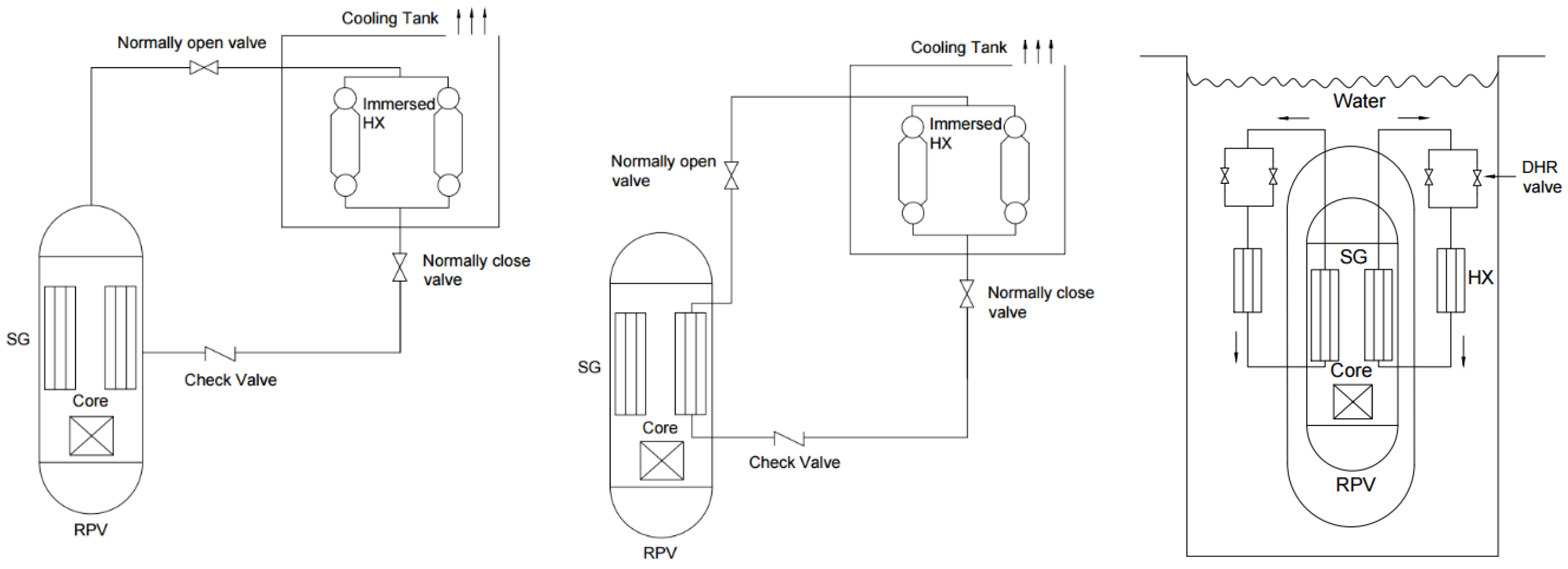
In a loss of normal heat sink conditions or a station black out scenario, a natural circulation mechanism is used in PRHRS to passively remove the residual core decay heat. PRHRS generally consists of one (1) or more trains to remove the decay heat, and also to provide redundancy [49]. The main component of each train is a heat exchanger (HX) immersed in a volume of water or air, at lower or ambient temperature. PRHRS is actuated by fail-safe valves (they usually fail open) with a loss of power or signal, which helps to transfer heat to the coolant via HX. PRHRS can be catagorised into three types with distinct system configurations and use of length, energy, number, distribution, information and time (LENDIT) heuristic scales [50]: (a) NC via coupled RPV and HX immersed in coolant tank; (b) NC via coupled steam generators with HXs in coolant tank (e.g., SMART), and; (c) NC via coupled steam generators with HXs in reactor pool (e.g., NuScale) (Figure 2) [18].

4.3.2. Passive Safety Injection System (PSIS)

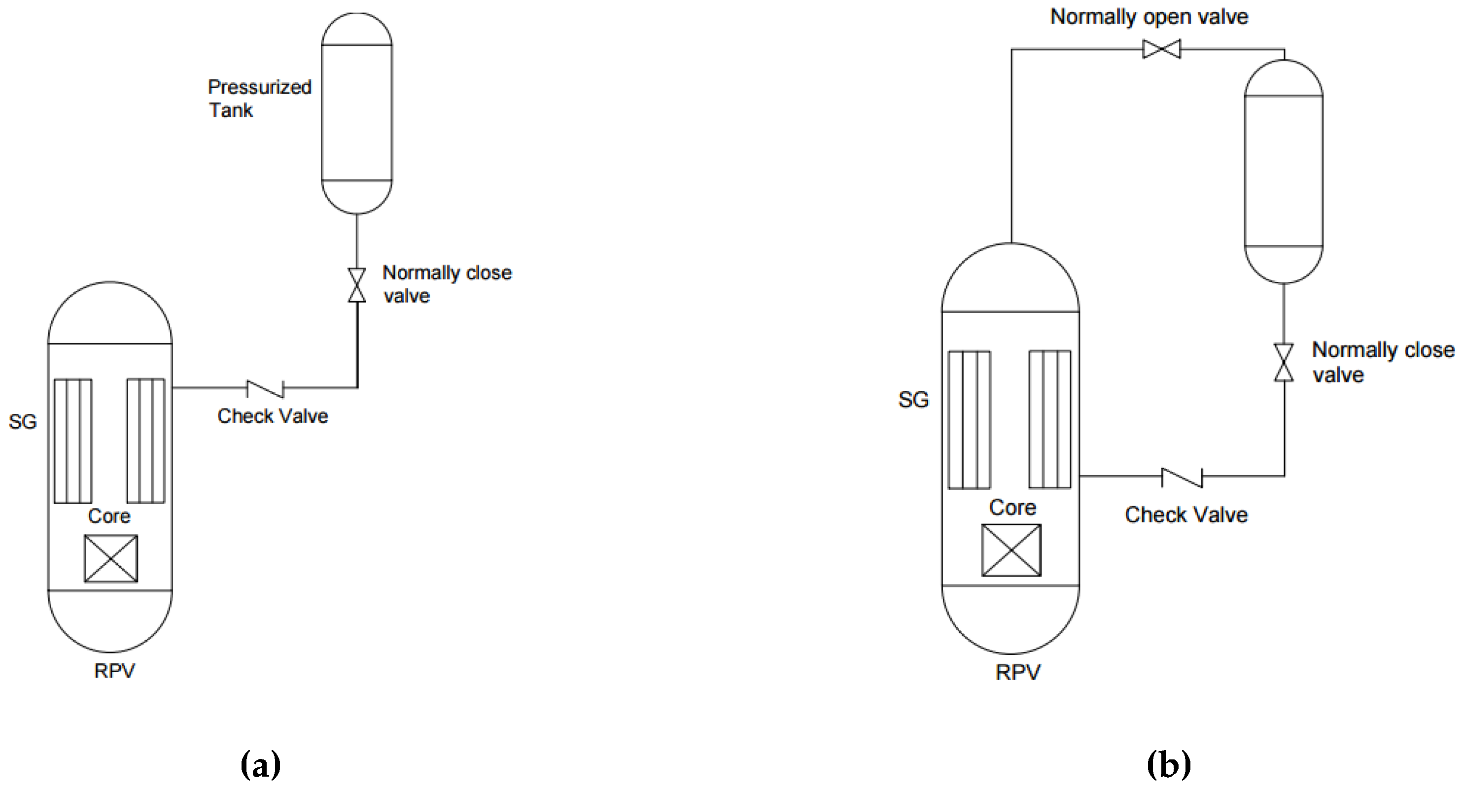
PSIS is used to control the reactor coolant inventory, as well as to remove the reactor decay heat. PSIS is usually deployed to counter loss of coolant accidents (LOCAs) when the active makeup system is unavailable. We note that, importantly, LOCA is distinct type of severe accident relative to Loss of Heat Sink (LOHS) or SBO. PSIS can be catagorized into two types: (a) one time injection (e.g., accumulator) (Figure 3a); and (2) Natural circulation injection (e.g., core makeup tank) (Figure 3b). One time injection PSIS is composed of a tank with borated water pressurized with nitrogen or other inert cover gas. It jointly adds coolant and reactivity control. The borated tank in natural circulation injection is connected with a normally open valve so that it is under system pressure. The iPWR SMR designs that implement these concepts include SMART [39], CAREM25 [23], and ACP100 [17,18].

4.3.3. Passive Depressurization System (PDS)

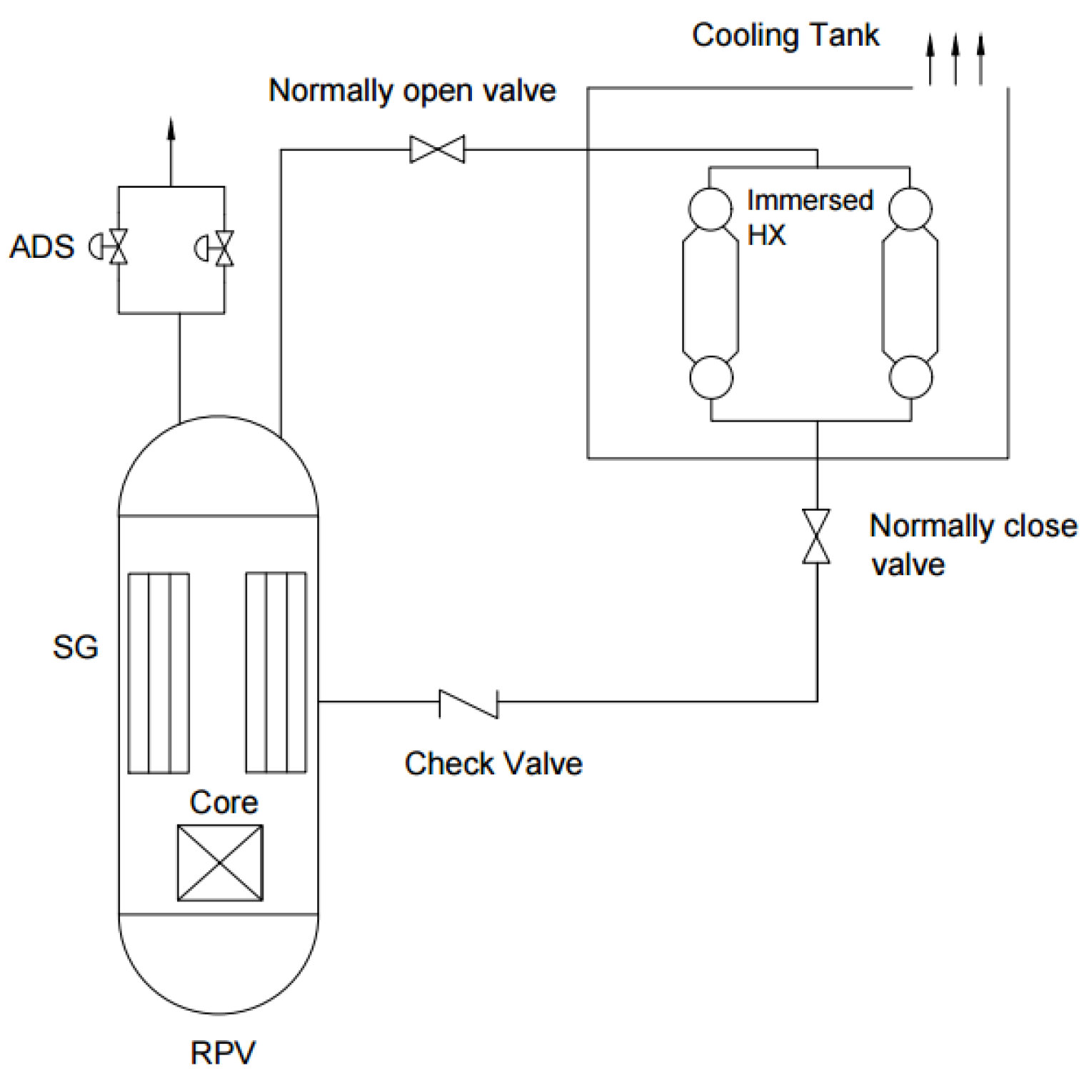
PDS is designed to decrease the pressure in RPV to enable safe injection. PDS can be catagorized into two types: (a) automatic depressurization system (ADS) (e.g., ACP100, SMART); and (b) natural circulation type (e.g., isolation condenser system in CAREM25) (Figure 4). ADS consists of several safety relief valves (SRVs) mounted on the main steam lines that are automatically operated in stages. The reactor pressure is reduced by releasing steam to be condensed outside the RPV. The NC type is similar to PRHRS in that the pressure is reduced by removing the decay heat outside RPV. It is operated by both RPV pressure and water level, and main steam line isolation valve (MSIV) closure fraction [18]. We note that the characteristic time-scales associated with depressurization are different in these two types.

4.3.4. Passive Containment Cooling System (PCCS)

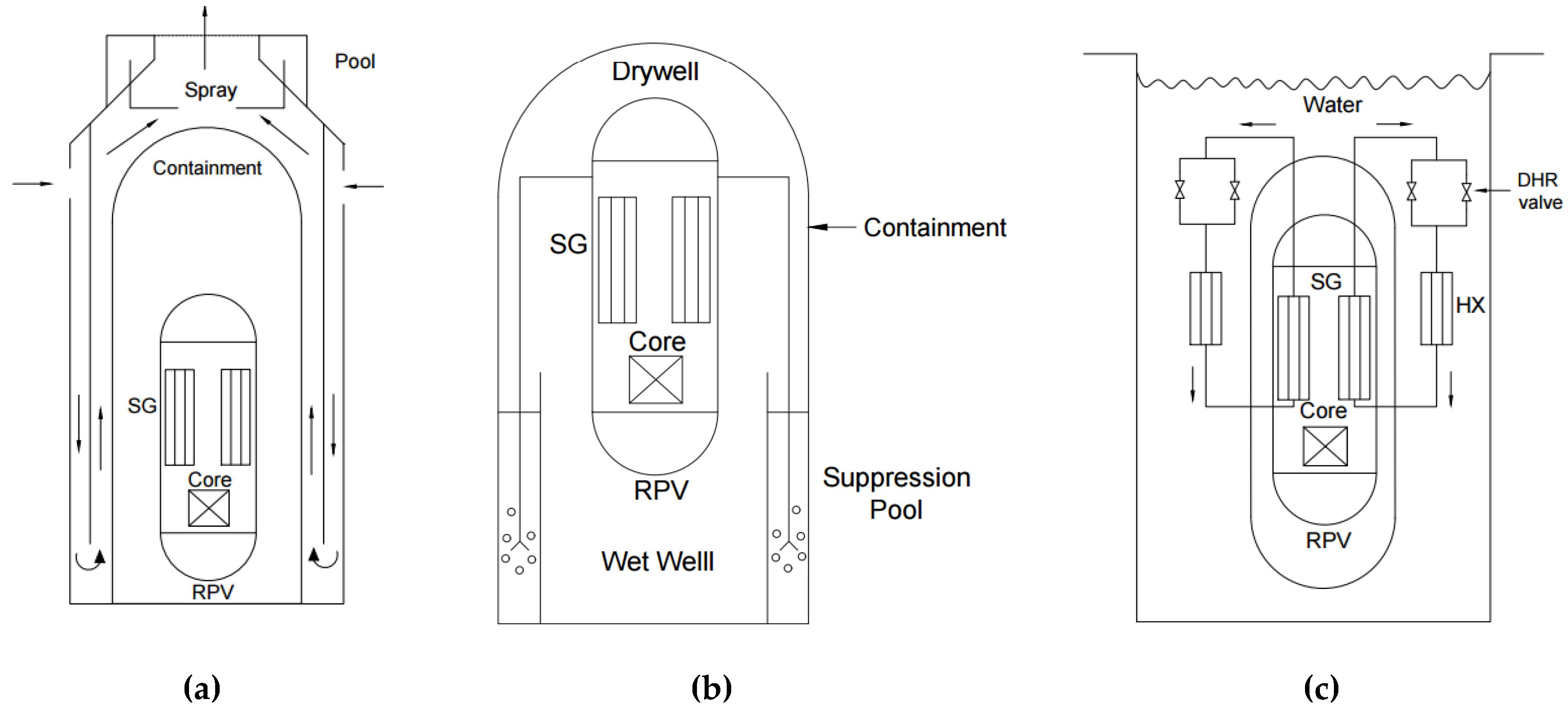
PCCS is used to maintain the integrity, pressure, and temperature inside the containment within the design limit. It is thus further removed from the primary energy systems. PCCS can be broadly classified into: (a) air cooled containment (e.g., ACP100); (b) pressure suppresion type (e.g., CAREM25); and (c) submerged containment (e.g., NuScale). Air cooled containment (Figure 5a) consist of a metal containment surrounded by reinforced concrete that allows for air circulation, thus condensing steam at the inner surface of the containment. In contrast, high temperature steam is directed to a suppression pool, mitigating pressure increases in the containment (Figure 5b). Lastly, a submerged containment is unique to iPWR-type SMRs; the metal containment is submerged in a water pool, allowing a continuous passive cooling of containment (Figure 5c). The steam released inside the containment is condensed; further heat is removed through the containment wall to the external water pool [18].

5. Passive Safety Systems in iPWR-Type SMRs

The implementation of PSSs is not unique to SMRs, rather the PSS was first implemented or at least conceptualized in large conventional GenIII and GenIII+ reactors such as ESBWR [9] and AP1000 [8]. Similar to these reactor concepts, all iPWR-type SMR designs implements simplified PSSs to counter and mitigate the remaining accident initiators and its consequences not covered by the inherent safety features. Additionally, in the wake of the Fukushima Daiichi accident, many iPWR-type SMR designs have been incorporating counter measures to cope with such severe accidents, including an endeavor to transform safety systems from hybrid to fully passive safety systems (e.g., SMART) [46]. Thus the question arises, what are the key differences in implementing PSSs in conventional reactors and iPWR type SMRs? Do the design characteristics of iPWR-type SMRs make them more suitable and effective for implementation of PSSs? If so, which features contribute to the effectiveness of PSSs in SMRs? Table 4 list expected advantages of implementing PSSs in iPWR-type SMRs.
Underlining the above yielded advantages through inherent design features, iPWR-type SMRs attempt to exploit these characteristics to achieve an increased safety margin. We note that all the iPWR-type SMRs considered follow a common set of design principles and approach to passive systems, despite a number of design differences. Table 5 presents a review and comparison of PSSs in iPWR-type SMR designs based on the targeted safety functions covering PRHRS, PSIS, passive reactor depressurization systems, and PCCS.

6. Challenges and Open Issues Related to Passive Safety Systems

While the advantages of PSS over active systems are well recognized within the international community [7], nevertheless several issues and challenges still remain that need to be consistently and effectively addressed, including uncertainties (aleatory as well as epistemic) which ultimately dictate the predicted system reliability and preformance, treatment of dependencies among system parameters, and consideration for time-dependent dynamic interactions between state variables and transition of system configurations, which is not accounted for by classic Probalistic Risk Assessment (PRA) techniques (ET/FT) [53]. Additionally, these challenges are magnified due to the unavailability of experimental data, lack of operating experience, and performance of PSS under normal and accident scenarios [54,55,56]. These issues are elevated in passive systems due to the possibility of functional failure, i.e., failure to accomplish the safety function/mission due to deviations in expected conditions/environment, rather than failure of mechanical components [57].
Uncertainties pertaining to PSS mainly arise due to factors that influence the low driving head and natural circulation mechanism. Representative factors include the presence of non-condensable gases, frictional losses, geometrical and materials properties, initial and boundary conditions, flow instability, heat loss, and oxidations. Any given deviation in driving head affects the coolant flowrate in the closed loop, which in turn influences the driving force, and thus causes a regenerative feedback mechanism [55]. The phenomenan and parameters affecting the performance of PSSs must be systematically identified, modelled, and quantified to represent a realistic system and add credit to the predicted system reliability [56]. PSS should accomplish this safety mission with a functional margin in order to compensate for the cummulative uncertainties that influence the system reliability. Here, we present a realistic scenario/example where uncertainties in NC may play a vital role to achieve critical safety function, and how these uncertainties may lead to additional safety requirements. The primary cooling mechanism based on NC is an improvement over coventional designs that requires primary coolant pumps. However, the performance of the NC mechanism during the postulated undesired events is yet to be proven, because in general, the heat transfer coefficient is smaller than the forced convective heat transfer applications. For instance, the activation of SDS2, i.e., boron injection into the RCS maybe impeded or delayed due to the small driving force of NC (start-up and time response). Of course, the time required for uniform distribution and dilution of boron in the reactor core will be higher compared to that using primary coolant pumps. This may be a challenge in terms of the regulatory requirements, and thus a proof of demonstration is a substantive argument. Thus, a scenario may require a dedicated pump (as a part of SDS2) in order to affect boron injection, and thus reactivity control. The rapid boron dilution event analysis and its subsequent contribution to the calculated core damange frequency has to be considered as well.
Dependencies in PSS mostly relate to critical thermal-hydraulic system parameters. If parameters have common contributors to their failure/deviation from nomminal value, the respective states of knowledge are dependent [54]. As noted by Burgazzi [58], dependencies may play a crucial role, and independent modelling of one passive attribute at a time may not be sufficent or adequate, rather simultaneous modelling of critical system parameters are required to capture the important boundary conditions. This may be more applicable to advanced designs with multiple PSSs, and that modelling of synergistic effects among the systems is important. Burgazzi [59] proposed an approach to treat dependencies among relevant system parameters which are indicators of PSS performance using bivariate probability distribution, i.e., construction of joint probability distribution function (PDF) to assess the functional reliability. However, the assignnment of PDF to relevant system parameters and assumed correlation coefficient among parameters are judgement dependent, which is a disadvantage.
Existing methodologies for reliability assessment of PSSs do not explicitly account for the following: (a) system dynamics; (b) time; (c) dynamic interactions; and (d) failure event ordering. These factors have an impact on the performance, end states and predicted reliability of PSSs. These dynamic characteristics are crucial for a system whose success/failure criterias are defined in terms of magnitude of process/state variables (e.g., RCS pressure), which is true for most PSSs. For instance, the mission of an ICS is to maintain the RCS pressure/peak cladding temperature within the design limit, or to remove the decay heat for a stipulated amount of time. However, classic techniques define system failure only in terms of combination of hardware or basic components failure (minimal cut-set). The assumption that a passive system is operating normally given that all the system hardware components are in normal state may not be necessarily true. This is because the controlled state variables for passive systems are not only dependent on the hardware states but also on system parameters (virtual components) such as heat loss, flow friction, oxidation and presence of non-condensable gases. Thus, there are two elements that may contribute to a failure of the expected performance: (i) failure of system components; and (ii) failure of physical process. For example, an ICS performance is dependent on these virtual parameters which eventually influence the control state variables, i.e., RCS pressure can transit out of the control region even if all the systems components are operating normally, due to the virtual components. These counter forces in PSSs based on NC cannot be neglected because of the comparable magnitude with the low driving force. Thus, the predicted reliability of a passive system considering only the hardware states may not be realistic or adequate. The extent to which these system parameters influence the predicted reliability and performance should be investigated further. Dynamic interactions within the PSS components, and with other safety systems (active/passive) through state variables can influence the state of a component/system or the transition rate from one system state to the other, and thus the failure probabilities or demand frequency of a system. For example, the ICS and safety relief valves (SRVs) are intended to maintain RCS pressure within design limit. The two systems interact through the RCS pressure, where the demand frequency of the SRVs are dependent on the performance of the ICS, i.e., for sucessful ICS operation, it eliminates the activation of the SRVs, and vice versa. Successful ICS operation can also eliminate/delay the activation of high pressure coolant injection system, which can also be the third interacting system. These dynamic interactions can result in accident scenarios not anticipated by classic techniques, and hence may not accurately quantify risk-significant sequence. The order and modes in which system components fail dictate the end state of a system, or at least governs the time distribution from an IE to an end state. This is especially true for system with multiple top events, where there maybe competition among the top events. For example, condensate valves in an ICS failing first will result to an instant termination of natural circulation, thus resulting in a relatively faster system failure, i.e., system failure from high RCS pressure. On the other hand, a first failure of the make-up water valves that supply water to the IC pool will take longer (in time) to develop into a system failure. This time, in turn, is depedent on the IC pool water temperature and water volume. Equally, the make-up valves failing-open will result in a low RCS pressure. The impact of this is that the probabilty of a failure event occuring first becomes important for accurately predicting system failure probability. Dynamic PRA provides a framework to address these issues in an integrated fashion by enabling one to account for deviations in boundary conditions, capturing parameter dependencies, performing integrated uncertainty analysis, and allowing for complete coverage of transient/accident scenarios.

7. Conclusions

The innovative configurations of iPWR-type SMRs provide intrinsic capabilities for enhanced safety and increased reliability through simpler design, a reduced number of components (active), inherent elimination of several potential accident initiators, and both short (24 h) and long system response via designed use of passive systems. These design features reduce the number of design-based accidents to be treated in the licensing process, as well as provide a more robust capability to counter the remaining initiators. While the primary purpose of this class of reactors is for electricity generation, iPWR-type reactors offer possibilities for cogeneration and synergetic energy systems with renewables, and thus additional ‘products’ such as medical isoptopes, thermal energy, and fluids. We note that all iPWR-type SMRs are based on proven technologies of existing commercial PWR reactors. This common heritage is in anticipation of ultimate cost and mitigation of risk assoicated with regulatory review. The literature review of technologies shows a common set of design principles and approach to safety, despite a number of design differences. This is particularly important so that regulators can call upon a framework that does not exist.
High-level of safety in iPWR-type reactors is assured by incorporation of passive systems based on natural laws, such as gravity and natural circulation. PSSs are perceived to be more reliable than active systems, due to their independence from external power sources, elimination or minimizeation of human intervention, and possible impacts in public acceptance. We note that the inherent design characteristics of iPWR-type SMRs, including taller vessel, larger coolant inventory, lower core power denstiy, and larger surface to volume ratio, provide significant advantages in implementing passive systems, in contrast to the conventional reactors. However, there still remains several challenges and technical issues with regard to reliability and performance assessment of PSS. These issue are compounded by the lack of operating experience, lack of experimental data, and significant uncertainties with regard to natural circulation phenomenon. These challenges should be addressed by rigorous separate and integral effect testing.
Besides the commercial and application viability of SMRs, the simplification observed in various SMR designs provides the opportunity to advance via integration, use of dynamic analyses in risk assessment, system codes and promising methods in machine learning, if in addition scaling of experiments is judiciously applied. Fernandez Gomez et al. [60,61] provide a review and initial consideration of applications of machine learning in the nuclear and radiological engineering technology fields. Additionally, dynamic PRA provide a platform for treatment of uncertainties in an integrated manner, enable systematic complete coverage of failure scenarios, accounting for integrated effects of system parameter deviations and random hardware failures, and capturing time-dependent dynamic interactions; all of which significantly influence the performance and reliability of PSSs. While many of these tools and sources of data (via integral and separate effect tests and simulations) exist for the legacy LWR fleet and Generation III+ concepts, dynamic methods are not adopted across industry and R&D because large LWRs typically mean computationally intensive simulations and very large state spaces (state explosion). This, importantly, suggests for the nuclear sector steps to realize a ‘digital twin’. Although the proprietary nature of any vendor’s reactor designs and simulations (both LWRs and SMRs), prevent full information sharing, SMRs provide a unique opportunity for integration of tools under dynamic analysis and scale input from machine learning such that safety principles and philopsophy—primarily defense-in-depth and INSAG 10—can perhaps be assessed as an iterative design practice.

Author Contributions

Conceptualization, C.Z. and A.T.; Methodology, C.Z.; Validation A.T., L.L. and A.R.; Formal Analysis, C.Z. and Y.M.; Investigation, C.Z. and Y.M.; Resources, C.Z., Y.M., L.L. and A.R.; Writing—Original Draft Preparation, C.Z.; Writing—Review & Editing, C.Z., Y.M. and A.T.; Supervision, C.Z.; Project Administration, C.Z.; Funding Acquisition, C.Z. and A.T. All authors have read and agreed to the published version of the manuscript.

Funding

This research was (partially) funded by the International Atomic Energy Agency under Grant No 21051.

Acknowledgments

This work (was partially) supported by the Coordinated Technical Project (CRP-I32010). (We thank the IAEA, including staff H. Sukki and F. Reitsma.).

Conflicts of Interest

The authors declare no conflict of interest.

References

  1. Subki, M.H. Advances in Development and Deployment of Small Modular Reactor Design and Technology. In Proceedings of the ANNuR-IAEA-USNRC Workshop on SMRs Safety and Licensing, Vienna, Austria, 12–15 January 2016. [Google Scholar]
  2. International Atomic Energy Agency. Innovative Small and Medium Sized Reactors: Design features, Safety Approaches and R&D Trends; TECDOC-1451; IAEA: Vienna, Austria, 2004. [Google Scholar]
  3. Subki, M.H. Update on International SMR Development and Deployment Activities. In Proceedings of the IAEA Technical Meeting on Roadmap for SMR Deployment, Vienna, Austria, 12 October 2015. [Google Scholar]
  4. Nuclear Energy Agency. Current Status, Technical Feasibility and Economics of Small Nuclear Reactors; Organisation of Economic Cooperation and Development: Paris, France, 2011. [Google Scholar]
  5. International Atomic Energy Agency. Deployment Indicators for Small Modular Reactors: Methodology, Analysis of Key Factors and Case Studies; TECDOC-1854; IAEA: Vienna, Austria, 2018. [Google Scholar]
  6. International Atomic Energy Agency. Advances in Small Modular Reactor Technology Developments; A Supplement to: Advanced Reactors Information System 2018 Edition; IAEA: Vienna, Austria, 2018. [Google Scholar]
  7. International Atomic Energy Agency. Technical Feasibility and Reliability of Passive Safety Systems for Nuclear Power Plants; TECDOC-920; IAEA: Vienna, Austria, 1994. [Google Scholar]
  8. Schulz, T. Westinghouse AP1000 advanced passive plant. Nucl. Eng. Des. 2006, 236, 1547–1557. [Google Scholar] [CrossRef] [Green Version]
  9. General Electric Company. The ESBWR Plant General Design Description; GE Nuclear Energy: Wilmington, NC, USA, 2007. [Google Scholar]
  10. Mizuno, Y.; Ninokata, H.; Finnicum, D.J. Risk-informed design of IRIS using a level-1 probabilistic risk assessment from its conceptual design phase. Reliab. Eng. Syst. Saf. 2005, 87, 201–209. [Google Scholar] [CrossRef]
  11. Danrong, S.; Quan, B. Small Modular Nuclear Reactor (SMR) Research and Development (R&D) and Deployment in China. In Proceedings of the ICAPP 2014, Charlotte, NC, USA, 6–9 April 2014; p. 14065. [Google Scholar]
  12. Hidayatullah, H.; Susyadi, S.; Subki, M.H.; Khan, H. Design and technology development for small modular reactors–Safety expectations, prospects and impediments of their deployment. Prog. Nucl. Energy 2015, 79, 127–135. [Google Scholar] [CrossRef]
  13. Ingersoll, D.T. An Overview of the Safety Case for Small Modular Reactors. ASME 2011 Small Modular Reactors Symposium 2011, 369–373. [Google Scholar] [CrossRef]
  14. Zeliang, C. Design Philosophy and Application of Defense-in-Depth Strategy in Integral Pressurized Water Reactor Type Small Modular Reactors; Journal of Nuclear Engineering and Technology: Amsterdam, The Netherlands, 2019. [Google Scholar]
  15. United State Nuclear Regulatory Commission. Design Certification Application–NuScale, Application Documents. 2020. Available online: https://www.nrc.gov/reactors/new-reactors/design-cert/nuscale.html (accessed on 14 May 2020).
  16. Mi, Y.; Zeliang, C.; Tokuhiro, A.; Lu, L. A Comparative Assessment of Passive Safety Systems in Integral Pressurized Water Reactor Type Small Modular Reactor. In Proceedings of the 27th International Conference on Nuclear Engineering (ICONE27), Tsukuba, Ibaraki, Japan, 19–24 May 2019. [Google Scholar]
  17. Qiu, Z.; Zhe, L.; Xiao, C. Design, Technology and Safety features of ACP100 for Near-Term Deployment in China. In Proceedings of the IAEA Reseach Coordination Meeting on “Design and Performance Assessment of Passive Engineered Safety Features in SMRs”; IAEA: Vienna, Austria, 2018. [Google Scholar]
  18. Zhe, L.; Zhifang, Q.; Xiao, C. Research on Approaches for Schematic Design and Performance Assessment of Passive Engineered Safety Features for ACP100. In Proceedings of the IAEA Reseach Coordination Meeting on “Design and Performance Assessment of Passive Engineered Safety Features in SMRs”; IAEA: Vienna, Austria, 2018. [Google Scholar]
  19. Danrong, S. Technology Roadmap for ACP100 Deployments. In Proceedings of the IAEA Technical Meeting on “Technology Roadmap for Small Modular Reactor Deployment”; IAEA: Vienna, Austria, 2015. [Google Scholar]
  20. International Atomic Energy Agency. Advances in Small Modular Reactor Technology Developments-A supplement to: Advanced Reactors Information System; IAEA: Vienna, Austria, 2016. [Google Scholar]
  21. World Nuclear Association. Small Nuclear Power Reactors. 2013. Available online: https://www.world-nuclear.org/information-library/nuclear-fuel-cycle/nuclear-power-reactors/small-nuclear-power-reactors.aspx (accessed on 1 May 2020).
  22. Delmastro, D.; Ishida Fukami, M.V.; Gomez, S.E.; Gomez de Soler, S.; Ramilo, L.; Santecchia, A.; Mazzi, R. CAREM: An Advanced Integrated PWR. In Proc. Intl. Seminar on Small and Medium Sized Reactors: Status and prospects, Eygpt; IEAE: Vienna, Austria, 2002. [Google Scholar]
  23. Magan, H.B.; Delmastro, D.F.; Markiewicz, M.; Lopasso, E.; Diez, F.; Giménez, M.; Rauschert, A.; Halpert, S.; Chocrón, M.; Dezzutti, J.C.; et al. CAREM Project Status. In Science and Technology of Nuclear Installations; Hindawi Publishing Corporation: London, UK, 2011; Volume 2011. [Google Scholar]
  24. Markiewicz, M. Fuel Element Design for the Fuel Element Element Design for the Carem-25 Reactor. In Proceedings of the Simposyum Small Modular Reactors for Nuclear Power, Rio De Janeiro, Brazil, 21–24 July 2014. [Google Scholar]
  25. International Atomic Energy Agency. Status of Innovative Small and Medium Sized Reactor Designs-Reactors with Conventional Refuelling Schemes; TECDOC-1485; IAEA: Vienna, Austria, 2005. [Google Scholar]
  26. International Atomic Energy Agency. Status report 95-Integrated Modular Water Reactor (IMR). In Advanced Reactor Information System; IAEA: Vienna, Austria, 2011. [Google Scholar]
  27. Carelli, M.D.; Conway, L.; Oriani, L.; Petrović, B.; Lombardi, C.; Ricotti, M.E.; Barroso, A.; Collado, J.; Cinotti, L.; Todreas, N.; et al. The design and safety features of the IRIS reactor. Nucl. Eng. Des. 2004, 230, 151–167. [Google Scholar] [CrossRef]
  28. Carelli, M.D.; Petrović, B.; Čavlina, N.; Grgić, D. IRIS (International Reactor Innovative and Secure)–Design Overview and Deployment Prospects. In Proceedings of the Proc. Intl. Conf. Nuclear Energy for New Europe, Bled, Slovenia, 5–8 September 2005. [Google Scholar]
  29. Halfinger, J.A.; Haggerty, M.D. The B&W mPower™ scalable, practical nuclear reactor design. Nucl. Technol. 2012, 178, 164–169. [Google Scholar]
  30. Halfinger, J. B&W mPower Reactor Design Overview Workshop; Babcock & Wilcox Company: Akron, OH, USA, 21 April 2011. Available online: https://www.nrc.gov/docs/ML1110/ML11102A097.pdf (accessed on 14 November 2019).
  31. Martin, R.P.; Williams, E.S.; Williams, J.G. Thermal-hydraulic Design of the B&W mPower SMR. Trans. Am. Nucl. Soc. 2013, 109, 2269–2272. [Google Scholar]
  32. NuScale Power, LLC. NuScale plant design overview. United States Nuclear Regulatory Commmission; NuScale Power, LLC.: Washington, DC, USA, 2012. [Google Scholar]
  33. NuScale Power, L.L.C. NuScale Standard Plant Design Certification Application. Chapter Six: Engineered Safety Features; PART 2-TIER 2; NuScale Power, LLC.: Washington, DC, USA, 2016. [Google Scholar]
  34. NuScale Power, L.L.C. NuScale Standard Plant Design Certification Application. Chapter Five: Reactor Coolant System and Connecting Systems; PART 2-TIER 2; NuScale Power, LLC.: Washington, DC, USA, 2016. [Google Scholar]
  35. Afrikantov OKBM, J.S.C. RITM: Reactor Plants for Nuclear-Powered Icebreakers and Optimized Floating Power Units; Afrikantov OKB Mechanical Engineering; Nizhny Novgorod, Russia. Available online: http://www.okbm.nnov.ru/upload/iblock/75f/75f548d37f50a51cb99c338bf3122970.pdf (accessed on 24 April 2020).
  36. Park, H.S. Specific Design Consideration of SMART for Application in the Middle East and North Africa Region. In Proceedings of the IAEA Reseach Coordination Meeting on “Design and Performance Assessment of Passive Engineered Safety Features in SMRs”, Vienna, Austria, 7 May 2018. [Google Scholar]
  37. Kim, K.K.; Lee, W.; Choi, S.; Kim, H.R.; Ha, J. SMART: The First Licensed Advanced Integral Reactor. J. Energy Power Eng. 2014, 8, 94. [Google Scholar] [CrossRef] [Green Version]
  38. Chang, M.H.; Kim, K.K.; Yeo, J.W. Advanced Design Features Adopted in SMART. In Proceedings of the intl. Seminar on Small and Medium Sized Reactors: Status and pospects, Cairo, Eygpt, 27–31 May 2001. [Google Scholar]
  39. Bae, H.; Yang, J.H.; Jeon, B.G.; Park, H.S. Thermal-hydraulic validation tests and their analyses on passive safety system for SMART. In Proceedings of the IAEA Reseach Coordination Meeting on “Design and Performance Assessment of Passive Engineered Safety Features in SMRs”; IAEA: Vienna, Austria, 2018. [Google Scholar]
  40. Chun, J.H.; Song, J.S.; Kang, H.O.; Kim, K.K. The Application of the Design Safety Requirements to the Passive SMART. In Proceedings of the IAEA Technical Meeting on Challenges in the Application of the Design Safety Requirements for Nuclear Power Plants to Small and Medium Sized Reactors; IAEA: Vienna, Austria, 2017. [Google Scholar]
  41. International Atomic Energy Agency. Status of Advanced Light Water Reactor Designs; TECDOC-1391; IAEA: Vienna, Austria, 2004. [Google Scholar]
  42. International Atomic Energy Agency. Status Report 66-VBER-300. In Advanced Reactors Information System; IAEA: Vienna, Austria, 2011. [Google Scholar]
  43. Fetterman, R.J.; Harkness, A.W.; Smith, M.C.; Taylor, C. An Overview of the Westinghouse Small Modular Reactor. In Proceedings of the ASME 2011 Small Modular Reactors Symposium, Washington, DC, USA, 28–30 September 2011; pp. 75–82. [Google Scholar] [CrossRef]
  44. Westinghouse Electric Company LLC. Westinghouse Small Modular Reactor Development Overview; IAEA: Vienna, Austria, 2011. Available online: https://www.nrc.gov/docs/ML1119/ML111920208.pdf (accessed on 5 March 2020).
  45. Liao, J.; Kucukboyaci, V.N. Modeling Passive Safety in the Westinghouse Small Modular Reactor–Assessment of Wall Condensation and CMT Natural Circulation. In Proceedings of the ASME Heat Transfer Summer Conference collocated with the ASME 7th International Conference on Energy Sustainability, and the ASME 11th International Conference on Fuel Cell Science, Engineering and Technology, Minneapolis, MN, USA, 14–19 July 2013. [Google Scholar] [CrossRef]
  46. International Atomic Energy Agency. Design Safety Considerations for Water Cooled Small Modular Reactors Incorporating Lessons Learned from the Fukushima Daiichi Accident; TECDOC-1785; IAEA: Vienna, Austria, 2016. [Google Scholar]
  47. Masuda, F.; Ono, Y.; Kinoshita, S.; Iwami, H. Introduction of (Safety Related Terms for Advanced Nuclear Plants) by IAEA. J. At. Energy Soc. Jpn. 1992, 34, 1116–1120. [Google Scholar] [CrossRef] [Green Version]
  48. International Atomic Energy Agency. Passive Safety Systems and Natural Circulation in Water Cooled Nuclear Power Plants; TECDOC-1624; IAEA: Vienna, Austria, 2009. [Google Scholar]
  49. International Atomic Energy Agency. Passive Safety Systems in Advanced Water Cooled Reactors (AWCRs), TECDOC-1705, case studies-A report of the International Project on Innovative Nuclear Reactors and Fuel Cycles; IAEA: Vienna, Austria, 2013. [Google Scholar]
  50. Nielsen, J.; Tokuhiro, A.; Hiromoto, R.; Khatry, J. Optimization method to branch-and-bound large SBO state spaces under dynamic probabilistic risk assessment via use of LENDIT scales and S2R2 sets. J. Nucl. Sci. Technol. 2014, 51, 1212–1230. [Google Scholar] [CrossRef] [Green Version]
  51. Carelli, M.D. Safety by Design: A new approach to accident management in the IRIS reactor, IAEA-SR-218/36. In Proceedings of the IAEA International Seminar on Status and Prospects of Small and Medium Sized Reactors, Cairo, Egypt, 27–31 May 2001. [Google Scholar]
  52. International Atomic Energy Agency. Design Features to Achieve Defence in Depth in Small and Medium Sized Reactors; Nuclear Energy Series NP-T-2.2; IAEA: Vienna, Austria, 2009. [Google Scholar]
  53. Zeliang, C. Dynamic Accident Sequence Analysis using Dynamic Flowgraph Method and Markov/Cell-to-Cell Mapping Technique. Master’s Thesis, University of Ontario Institute of Technology, Oshawa, ON, Canada, 1 January 2018. [Google Scholar]
  54. Burgazzi, L. Evaluation of the dependencies related to passive system failure. Nucl. Eng. Des. 2009, 239, 3048–3053. [Google Scholar] [CrossRef]
  55. Nayak, A.; Chandrakar, A.; Vinod, G. A review: Passive system reliability analysis–accomplishments and unresolved issues. Front. Energy Res. 2014, 1, 40. [Google Scholar] [CrossRef] [Green Version]
  56. Burgazzi, L. Addressing the uncertainties related to passive system reliability. Prog. Nucl. Energy 2007, 49, 93–102. [Google Scholar] [CrossRef]
  57. Burgazzi, L. Reliability Evaluation of Passive Systems Through Functional Reliability Assessment. Nucl. Technol. 2003, 144, 145–151. [Google Scholar] [CrossRef]
  58. Burgazzi, L. Addressing the challenges posed by advanced reactor passive safety system performance assessment. Nucl. Eng. Des. 2011, 241, 1834–1841. [Google Scholar] [CrossRef]
  59. Burgazzi, L. Reliability Prediction of Passive Systems Based on Bivariate Probability Distributions. Nucl. Technol. 2008, 161, 1–7. [Google Scholar] [CrossRef]
  60. Fernandez, M.G.; Tokuhiro, A.; Welter, K.; Wu, Q. Nuclear energy system’s behavior and decision making using machine learning. Nucl. Eng. Des. 2017, 324, 27–34. [Google Scholar] [CrossRef]
  61. Gomez-Fernandez, M.; Higley, K.A.; Tokuhiro, A.; Welter, K.; Wong, W.-K.; Yang, H. Status of research and development of learning-based approaches in nuclear science and engineering: A review. Nucl. Eng. Des. 2020, 359, 110479. [Google Scholar] [CrossRef]
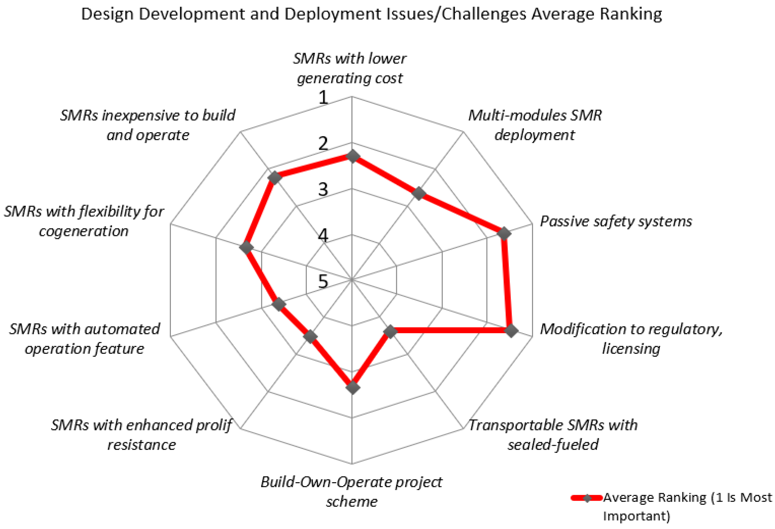
Figure 1. Average ranking of identified challenges for design development and deployment [1]. Reproduced from [1], IAEA: 2016.
Energies 13 02898 g001
Figure 2. Passive residual heat removal system (PRHRS) coupled with reactor pressure vessel (RPV) and coupled with steam generators (SGs) (heat exchangers (HXs) immersed in cooling tank and reactor pool).
Energies 13 02898 g002
Figure 3. (a) One time injection system, (b) natural circulation (NC)-based injection system.
Energies 13 02898 g003
Figure 4. Passive depressurization systems.
Energies 13 02898 g004
Figure 5. (a) Air cooled, (b) suppresion type, (c) pool type.
Energies 13 02898 g005
Table 1. Current integral pressurized water reactor (iPWR)-type small modular reactor (SMR) designs and status.
Technology DeveloperReactor DesignDesign Status
China National Nuclear Corporation (CNNC) ACP100Under development
Shanghai Nuclear Engineering Research and Design Institute (SNERDI)CAP150Conceptual design completed
Argentina’s National Atomic Energy Commission (CNEA)CAREM25Under construction
Mitsubishi Heavy Industries, LtdIntegrated Modular Water Reactor (IMR)Conceptual design completed
International ConsortiumInternational Reactor Innovative and Secure (IRIS)Basic design
BWXT mPower, Inc.mPowerUnder development
NuScale Power, LLCNuScaleLicensing stage
OKBM AfrikantovRITM-200Under construction
Korea Atomic Energy Research Institute (KAERI)System-integrated Modular Advanced ReacTor (SMART)Licensed
OKBM Afrikanto VBERLicensing stage
Westinghouse Electric Company LLCWestinghouse SMRConceptual design completed
Table 3. Key advantages of passive safety systems.
Design FeaturesAdvantages
Design simplification and relatively less complexity than active systemsLess maintainance; economic competiveness
System operates on natural physical laws or forces, e.g., gravityNo external power source required; eliminates loss of power accident; reduced dependent failures such as common cause; better impact on public acceptability
Minimized active system componentsHigh system reliability; enhanced safety
Passive nature of PSSsEliminate/reduce reliance on operator action
Eliminate/reduced reliance on operator actionReduced human error; improved human reliability due to the exclusion/reduction of operator error in the analysis
Table 4. Potential advantages of implementing passive safety systems (PSSs) in iPWR-type SMRs.
Design CharacteristicsFacilitates for PSSs Start-up/Operation
Integral RCS design- reduced accident initiatorsMinimized accident initiators to cope with/mitigate using PSS, resulting to a simplified design [14,46,51]
Lower core power capacityLower decay heat to be removed [51]
Larger surface to volume ratiFacilitates easier decay heat removal due to large surface area particularly for single phase flow
Larger primary coolant inventory per MW(th)Larger heat sink for natural circulation; higher buoyancy force; reduced requirements for heat removal systems; slow transient and accident progression [12]
Less reactor core power densityLarger thermal-hydraulics margin; facilitates long term decay heat removal using PSSs
Large secondary coolant inventoryFacilitates passive decay heat removal and containment cooling [32], e.g., NuScale
Taller reactor pressure vesselFacilitate for decay heat removal via natural circulation, i.e., higher elevation difference between heat source and sink and increased coolant inventory [52]
Smaller radial core and pressure vesselA shorter distance from the core centerline to the reactor vessel, thus allowing better radial coupling of the decay heat from the reactor core to the vessel [13]
Table 5. Comparison of passive safety features in iPWR-type SMRs [18]. Reproduced from [18], IAEA.: 2018.
SMR DesignsPassive Safety Systems
PRHRSPSISPDSPCCS
CAREM25 [23,41]Number of trains2 train (RPV side)2 accumulators 3 ADS + 2 train ICS Pressure-suppression type
System components Parallel horizontal U-tubes (condensers), water storage tank, and inlet-outlet valves and connecting pipes to the RPVBorated water accumulators (ACC), injection line, and associated valves and pipingADS: safety relief valves with 100% capacity each ICS: Same as PRHRS Drywell, and wet well (suppression pool and gas compression chamber)
Mission time (hours)3648NA72
SMART [39,40]Number of trainsFour (4) trains with 33.3% capacity each (secondary side)Four (4) trains with 33% capacity each (CMTs + SITs)ADS: Two (2) trains with two (2) stages eachContainment pressure and radioactivity suppression system (CPRSS)
System componentsEmergency cool down tank, HXs, and make-up tank, check and isolation valves and instrumentationPressurized coolant tanks, pressure balance and safety injection line, isolation valves and associated piping Automatic depressurization valves, vent lines, sparger, piping and IRWSTCPRSS lid, HX, IRWST, and IRWST vent line, pressure relief line, sparger, lower and upper containment area
Mission time (hours)7272NA72
NuScale [32]Number of trains2 trains with 100% capacity each (secondary side)2 trains with 100% capacity each2 trains with 100% capacity each A CNV immersed in reactor pool
System componentsTwo condensers in reactor pool, SGs, and actuation valvesReactor vent valves (RVVs), and reactor re-circulation valves (RRVs)Reactor vent valves and associated pipingRVVs, RRVs, RPV, CNV, and the reactor pool
Mission time72 h72 hNA72 h, and thereby air cooled after 30 days
ACP100 [11,17]Number of trains2 trains (secondary side) 2 trains CMT + 2 ACCs + 2 trains IRWST injectionADS: two (2) trains with three (3) stages Air cooled with 2 trains + gravity drain lines
System componentsImmersed HXs, IRWST, and associated valves, piping and instrumentation CMT: pressurized coolant tanks, pressure balance line, isolation valves and associated piping
ACC: similar to CAREM25
IRWST: storage tank, injection lines and associated valves
Automatic depressurization valves IRWST, and pipingCylindrical steel containment vessel, containment cooling tank, air baffle, associated piping and valves
Mission time (hours)72 72 NA Not specified
mPower [31]Number of trains2 trains (secondary side)1 train one-time injection + 2 trains NC based via IRWST 4 low + 4 high pressure depressurization paths Natural convection inside the containment + conduction heat transfer to passive containment cooling tank
System componentsAn auxiliary steam condenser, cooling tank, and associated valves One time: nitrogen pressurized ACC, injection line and associated valves
NC based: IRWST, direct vessel injection line and associated valves
Depressurization valves and pipingAn integral water tank at the top of the containment in direct contact with containment dome structures that facilitates the heat transfer
Mission time72 h7 daysNABeyond 72 h
CAP150 [20]Number of trains2 trains with 100% capacity each (secondary side)Low pressure injection systemEliminated by designSteel containment submerged in containment pool
System componentsImmersed HXs, IRWST, isolation valves and associated pipingRefueling water tank, auxiliary depressurization system and associated valves and pipingContainment water pool, RPV and supplement pool
Mission timeNot specifiedNot specified7 days
IRIS [27] Number of trains4 trains (secondary side)2 trains (at system pressure)4 train EHRS + 2 trains ADS with one (1) stagePressure-suppression type
System componentsEmergency heat removal system (EHRS): horizontal U-tube HX, RWST, SG, SG make-up tank, connecting pipes and valvesEmergency boration tank, direct vessel injection line, redundant valves, and associated pipingAutomatic depressurization valves, suppression pool, sparger, and pipingSix (6) water tanks, a common tank for non-condensable gas storage, vent pipe and sparger
Mission time72 hNot specified72 hNot specified
IMR [6,25]Number of trains2 trains (secondary side)Eliminated by design
System componentsPassive SGs cooler in vapor and water, SG cooling tanks, exhaust and intake vent for air cooling, and associated valves and piping
Mission timeUnlimited time
W-SMR [43,45]Number of trains4 trains (primary side) via direct vessel injection (DVI) +2 trains (secondary side) via steam drum4 trains of CMTs (high pressure) and 2 trains of ICP injection (low pressure)4 trains of ADS (4 stages) + 2 trains of PORVs above the steam drumContainment vessel submerged in containment pool + 2 in-containment pool (ICP)
System componentsPrimary side: CMT, HXs, DVI line, ultimate heat sink (UHS), CMT pressure balance line, and associated valve
Secondary side: SG, steam drum, and associated valves and piping
System pressurized borated tank, DVI lines, and associated valves and piping
ICP injection: containment sump, ICP tank, sump injection line and check valves
Valves attached at the line of CMT, valves at the top of the ICP tanks and valves into the RPVSteel containment vessel, containment pool (outside), UHS, and valves connecting the containment pool with the UHS
Mission time72 h72 hNA7 days
RITM-200 [20]Number of trains2 passive trains (secondary side) + 2 active trains 2 passive trains + 2 active trains (one-time injection) Not specified, but similar to KLT-40S 2 trains
System componentsPassive: DHRS tank, a HX immersed in DHRS tank, a water storage tank and air cooled HXPassive: pressurized hydraulic accumulators, injection line, and associated valvesNot specified, but similar to KLT-40SHXs in and outside the containment, storage tank and associated valves
Mission time72 h72 hNANot specified
VBER-300 [25,42]Number of trains2 trains (secondary side) 2 trains (2 stages ACCs)2 trains2 trains
System componentsPassive in-built HXs, water tank and a process condenserParallel hydraulic ACCs, injection line, and associated valvesConventional SRVs at the top of the pressurizerHX immersed in water storage tank, HX inside the containment, and associated valves and piping
Mission time (hours)7224NANot specified