Article

A Novel Hybrid Search and Remove Strategy for Power Balance Wireless Charger Deployment in Wireless Rechargeable Sensor Networks

Department of Management Information System, National Chiayi University, Chiayi 60054, Taiwan
*
Author to whom correspondence should be addressed.
Energies 2020, 13(10), 2661; https://doi.org/10.3390/en13102661
Submission received: 29 February 2020 / Revised: 15 May 2020 / Accepted: 20 May 2020 / Published: 25 May 2020
(This article belongs to the Special Issue Wireless Rechargeable Sensor Networks 2019)

Abstract

:
Conventional sensor nodes are often battery-powered, and battery power limits the overall lifetime of the wireless sensor networks (WSNs). Wireless charging technology can be implemented in WSNs to supply power to sensor nodes and resolve the problem of restricted battery power. This type of mixed network is called wireless rechargeable sensor networks (WRSNs). Therefore, wireless charger deployment is a crucial task in WRSNs. In this study, the method of placing wireless chargers to efficiently extend the lifetime of the WRSNs is addressed. Owing to the data forwarding effect in WSNs, sensor nodes that are closer to the data collection or sink node drain more power than nodes that are further away from the data collection or sink node. Therefore, this study proposes a novel hybrid search and removal strategy for the power balance charger deployment method. The wireless chargers are placed in the chosen nodes of the WRSNs. The node-chosen problem we address is called the dominating set problem. The proposed hybrid search and removal strategy attempts to discover the minimum number of chargers required to cover all sensor nodes in the WRSN. The proposed algorithm considers the charging power of the wireless directional charger when arranging its placement to maximize the charging capacity in a power-balanced prerequisite. Therefore, the proposed deployment strategy preserves the awareness of the presence of the sink node that could result in unbalanced power distribution in WRSNs. The simulation results show that the proposed strategy spares more chargers and achieves better energy efficiency than other deployment approaches.

Graphical Abstract

1. Introduction

In a wireless sensor network (WSN), the amount of power provided by the battery determines whether each sensor can operate normally. Such power limitations also affect the stability of the entire WSN. To solve the problem of limited battery power, scholars have proposed studies on the design of energy-efficient routing protocols [1] and energy-harvesting wireless sensor networks (WSNs) to reduce energy consumption [2]. Neither the energy-efficient protocols nor the energy-harvesting WSNs solves the principle problem. These studies can prolong the life of WSNs. However, when the sensor exhausts the battery, the WSNs still cannot work properly. Some might argue that WSNs using solar energy can solve the problem of battery exhaustion. However, solar energy-based sensors are affected by environmental factors, and the efficiency of WSNs is significantly affected by different environments. In recent years, some researchers have proposed wireless charging technology, which can solve the problem of sensor battery power limitation, thus fundamentally solving the WSN lifetime problem [3]. The power can be transmitted using wireless chargers to RFIDs [4], sensors [5] and other terminal devices. TechNavio’s market research shows that wireless charging technology has great market potential, and the 2020 global annual increase in the wireless charging market is more than 33% [6]. Due to the convenience and continuous development of wireless charging technology, wireless charging has drawn the attention of both industry and academia, especially in the realm of WSN research.
The adoption of wireless charging technology to improve the survival time of WSNs has been extensively surveyed. The new type of WSN that allows wireless chargers to extend the lifetime of wireless sensors is called wireless rechargeable sensor networks (WRSNs). The main consideration for the deployment of wireless chargers in WSNs is to maintain a stable power supply for the sensors so that the sensors can perform sensing tasks in the sensing area. Based on cost considerations, the number of wireless chargers in this deployment area should be minimized. However, because the power supply of the sensors has a significant impact on the performance of the WSNs, this study attempts to find a deployment strategy that can effectively reduce the number of wireless chargers while maximizing the charging capacity.
Several studies related to the deployment of wireless chargers in WRSNs have been proposed in recent years. However, these studies have some limitations, such as the grid partition that does not fit to the real environment in which the charger can be placed. Some might unrealistically assume that the data collection node or sink node does not exist. The data collection node or sink node in WSNs or WRSNs is a critical device. The sensors collect and route data to a data collection or sink node. If a sensor is near the data collection or sink node, it will bear frequent data forwarding and consume more energy. Therefore, to address the limitations of previous research, this study explores the deployment of directional chargers in a given network. In this study, the influence of data collection or sink nodes is evaluated. Previous studies have failed to address this influence. We also deal with two different types of chargers: omnidirectional and directional chargers in WRSNs. In this study, a two-stage strategy called search most and remove useless (SMRU) is proposed. In the first stage, the candidate position of the directional charger is selected on a sensor randomly. Next, we search for the number of sensors covered by the chargeable radius at the candidate position of the directional charger. The deployment given by the proposed SMRU strategy can effectively reduce the required number of directional chargers and preserve good charging utility. The experimental results demonstrate that our proposed SMRU approach outperforms previous works.
The three main contributions of the proposed SMRU algorithm are as follows:
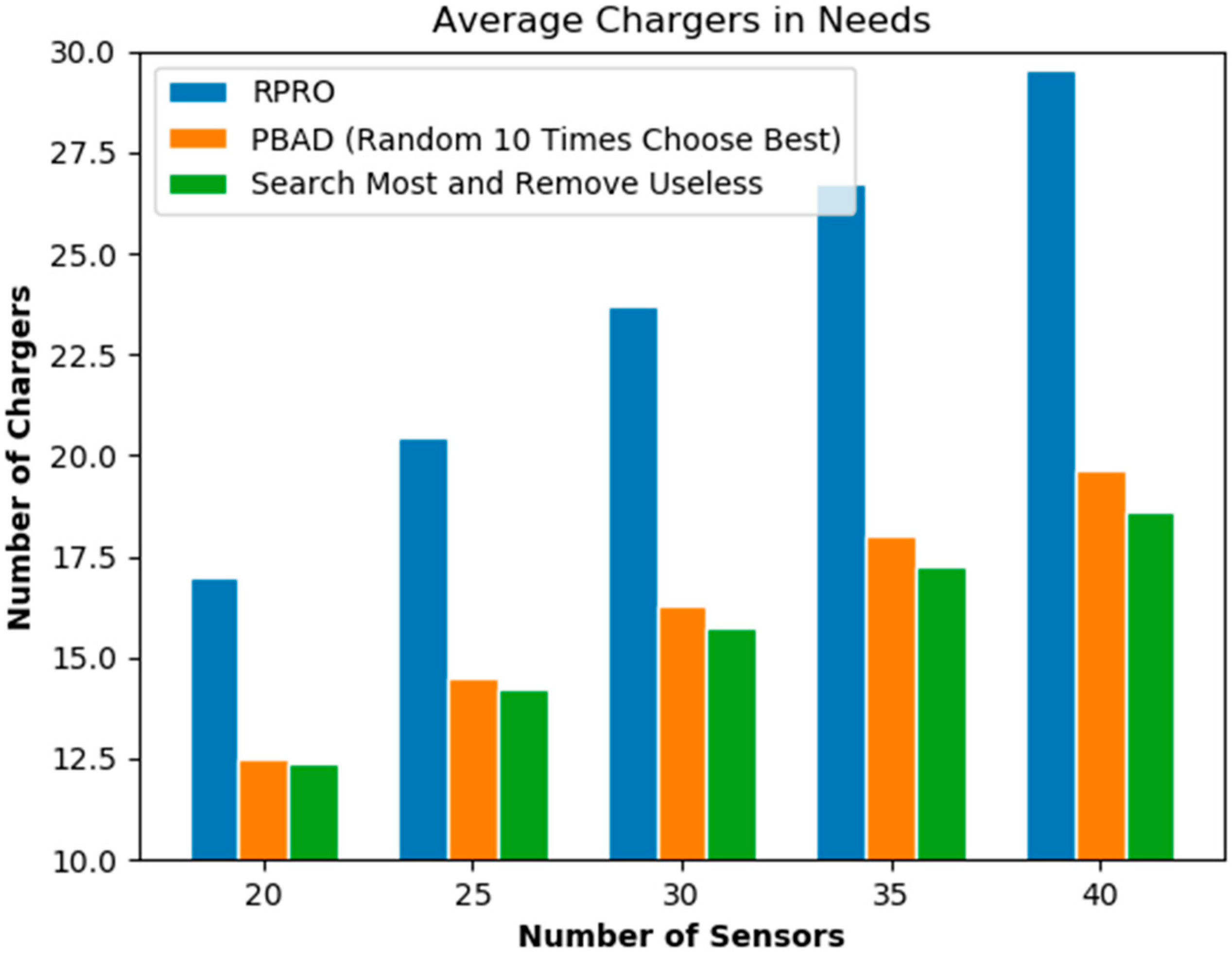
  • The SMRU algorithm can deploy the chargers in the WRSN in less time, and the number of chargers required is relatively small.
  • When the sensor position moves, the SMRU algorithm takes less time to correct and deploy the charger positions.
  • The SMRU algorithm can calculate the energy consumption of the sink node. Under the premise of supplying enough power to the sink node, the mechanism of the SMRU algorithm can reduce the number of chargers used to charge the sink node without affecting the number of chargers that charge other sensors.
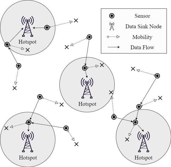
The structure of this study is as follows. In Section 2, this study investigates the relevant literature and explores the problems of some deployment strategies. In Section 3, the problem description is presented. Section 4 presents the details of the proposed algorithms. Section 5 explains the experimental results and give conclusions.

2. Related Works

2.1. Omnidirectional and Directional Chargers

Previous studies assumed that omnidirectional chargers have the same charging capacity at the same distance [7,8]. When the distance increases, the received power decays, and when the threshold distance is finally reached, the received power becomes zero. The charging range of an omnidirectional charger is defined as the center of the charging range. The coverage area of the directional charger is a sector [7,8]. Devices from different manufacturers may have different ranges of charging angles. Due to the somewhat steady power coverage and low cost, directional chargers are frequently used in WRSNs.
As the mathematical formulation of a charger’s charging power, previous researchers defined the charging formula as follows (1) [9,10,11]:
W ( d i s t ( a i , s i ) ) = { α ( d i s t ( a i , s i ) + β ) ) , d i s t ( a i , s i ) r 0 , d i s t ( a i , s i ) > r .
In Equation (1), dist(ai,si) is the Euclidean distance between charger ai and sensor si α = ξ W 0 G a G s C W ( λ 4 π ) 2 , λ is the wavelength, and ξ is the utility of the rectifier. Ga and Gs are the antenna gains of the charger and the sensor, respectively. W0 is the charger power and β is the compensation parameter for short-distance transmission and Cw in α is polarization mismatch loss [9]. When the range is larger than the charging radius r, the charging power is set to 0.

2.2. Wireless Charger and Sensor Deployment

The deployment of wireless chargers has drawn much attention recently. Several studies have been conducted in this area. He et al. proposed an energy provisioning method for wireless rechargeable sensor networks [12]. The proposed method addressed omnidirectional wireless charger deployment, and the wireless chargers were deployed in the region of interest to supply sufficient charging power to support the operations in WRSNs. However, He et al. probe the region using a conventional triangular method. Chiu et al. proposed a mobility-aware charger deployment scheme for WRSNs [13]. The wireless charger placement methods proposed by Chiu et al. [13] considered the trajectories of mobile sensors. The methods partitioned the regions into grids, and omnidirectional wireless chargers were arranged on grid intersections. Liao et al. scheduled the sleep period of wireless chargers to reduce the wastage of battery power and adopted a conical structure to cover the region [7]. In contrast to studies on omnidirectional sensor deployment, some researchers have carried out studies on directional sensor deployment, which present the directional angle concept [8,14]. Horster and Lienhart discussed the placement of visual sensors that are directional, and the angles of the devices are considered [8]. According to Horster and Lienhart, the monitoring area of a visual sensor is directional and triangles are used to represent the scope [8]. Therefore, they proposed the integer linear programming solving technique to calculate the optimal coverage, and every grid intersection represented a possible site of the placement [8]. As the deployment of wireless chargers can be formulated as a nonlinear programming problem, the deployment problem befits to the NP hard problem class [15]. Therefore, solving the wireless charger deployment problem is a challenging task. Han et al. studied the deployment of directional sensors [14]. In their study, the number of deployed directional sensors was minimized, and the connections among the sensors were considered. Mo et al. addressed the coordination problem among multiple mobile chargers and formulated the multiple mobile charger coordination problem as mixed-integer linear programming and proposed a decomposition approach to solve the problem [16]. Tang et al. simultaneously considered both charging and routing and proposed an optimization approach to extend the lifetime of the network [17]. In order to balance the network energy, charging efficiency is dynamically balanced and the charging time is partitioned according to the energy consumption. Chen et al. proposed a WRSN model equipped charging drone [18]. A scheduling algorithm to solve the shortest multi-hop path is developed for the charging drone.
Most studies did not address the impact of unbalanced battery power distribution caused by data forwarding to the sink node. Unbalanced battery power distribution can make some sensor nodes, especially those near the sink node, lose power quicker than other nodes. Previous research did not consider the existence of a data collection node or sink node. Although the assumption can allow chargers in an actual environment to be better optimized for deployments, the deployments would actually result in an unbalanced battery power consumption issue. To address the unbalanced battery power distribution controversy, Lin et al. proposed a power balance aware deployment (PBAD) method for wireless chargers and compared the PBAD with random position and random orientation (RPRO) [10]. They formulated the deployment as a minimum dominating set problem and attempted to discover the minimal number of chargers required to cover the networks in the WRSNs. Lin et al. adopted a greedy algorithm to calculate the coverage set, and the influence of the data sink node was weighted to attain full coverage [10]. Lin et al. proposed a two-stage method. First, the chosen region was split into several sub-areas, so that each sub-area could have a continuous supply of charging power. Next, every sub-area was further evaluated to find the minimum dominating sets, after which an approximated optimal dominating set was chosen. The reviewed literature is tabulated in Table 1.

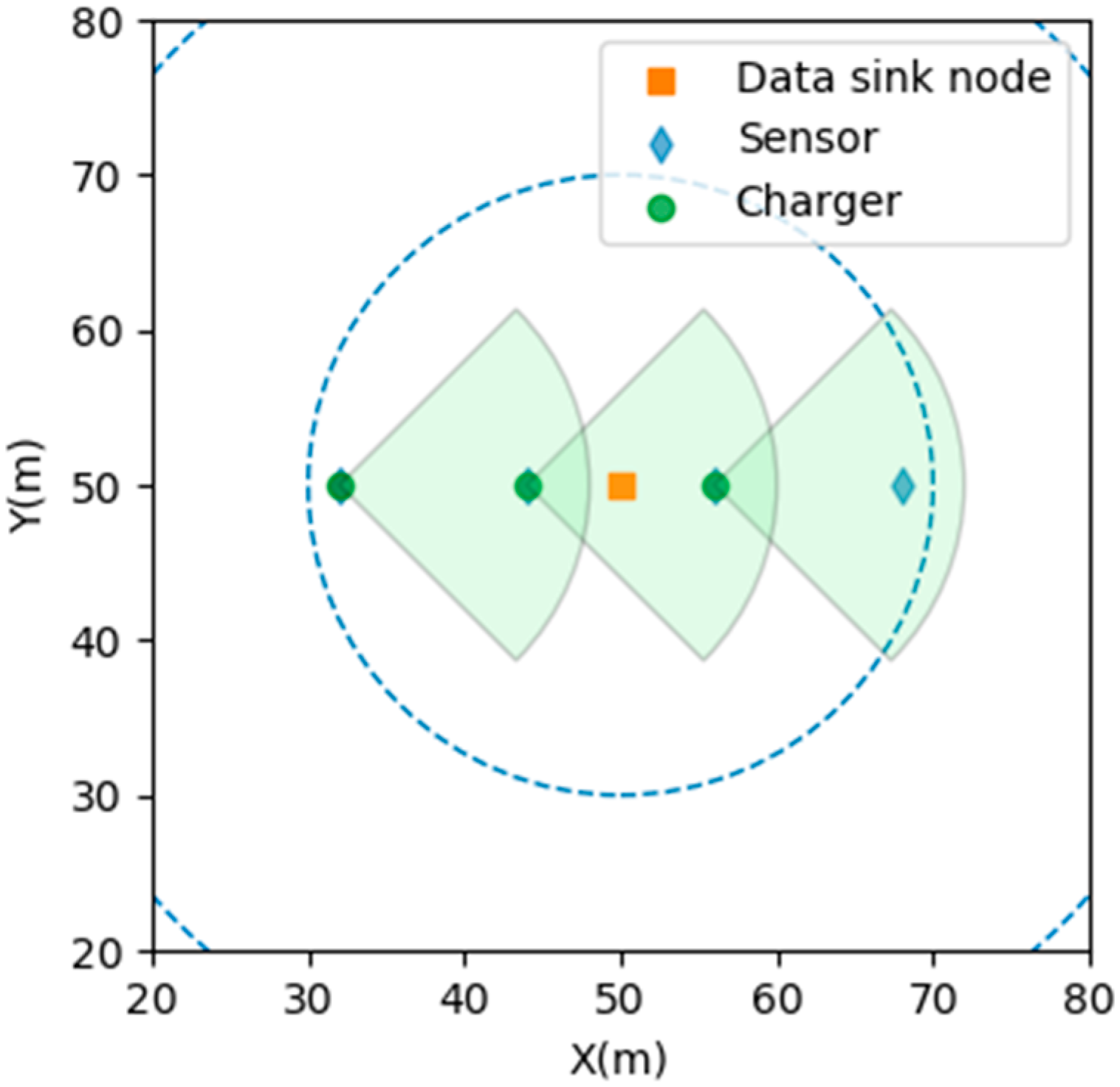
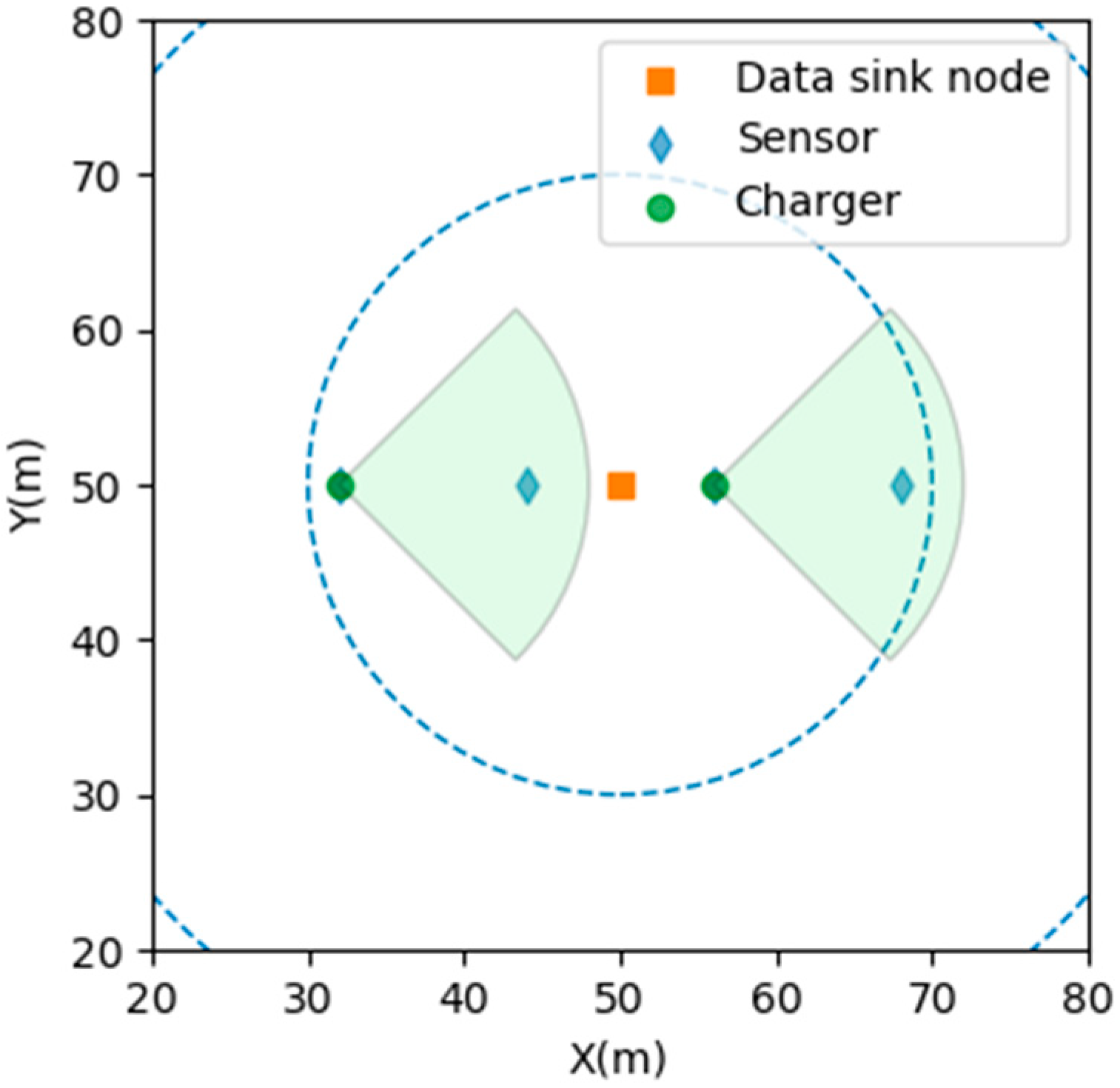
3. Search Most and Remove Useless Algorithm

3.1. Problem Definition

There are several problems with wireless sensor network applications. Among them, the power and cost of sensors are often the focus of research. In a wireless sensing network, the sensor must operate continually to maintain the function of receiving and transmitting the information. Therefore, reducing the sensor’s power consumption and extending battery life is an important problem. The network architecture called wireless rechargeable sensor network (WRSN) relies on the chargers to continuously supply the sensors with continuous power. In far-field phased arrays, wireless power can be transmitted through beams, while power beam transmission technology can transmit energy over longer distances. The wireless power transfer method proposed in the simulation design in this research is far-field phased array antennas [19]. As the deployment of wireless sensing networks may use a large number of sensors, the use of fewer chargers in WRSNs to provide sufficient power for the sensors to reduce deployment costs and maintain the operation of WRSNs is an important issue. Therefore, this study proposes a method that uses fewer directional chargers to cover all sensors in WRSNs. In our proposed method, the deployment position of the charger can be calculated in a short time. Additionally, all sensors in WRSNs are covered with a small number of chargers, and all sensor power is supplemented to avoid sensor interruption due to power consumption causing WRSNs to fail, and to reduce the cost of deploying a WRSN.

3.2. The SMRU Algorithm

The algorithm is divided into two parts. In the first part, the candidate position of the directional charger is selected on a sensor randomly. Next, we search for the number of sensors covered by the chargeable radius at the candidate position of the directional charger. The candidate position rotates 360° to find the angle that can cover most of the sensors within the charging range. If the number of sensors covered by the candidate position of the directional charger is more than three, the algorithm is repeated for each candidate position within the chargeable radius. To find the angle that can cover most of the sensors within the charging range, the position that covers the most sensors is selected as the new position of the directional charger. If the number of sensors covered by the candidate position of the directional charger is less than three, the candidate position is determined as the position of the directional charger. In the second part, after determining the position of the directional charger, the proposed algorithm checks whether there is an unnecessary position of the directional charger. Therefore, the algorithm checks and removes the charger, and the sensors covered by the charger can be covered by other chargers. This check action can effectively reduce the number of chargers. The operation of SMRU represented as Algorithm 1 is as follows:
Algorithm 1 Search the least needs of the chargers
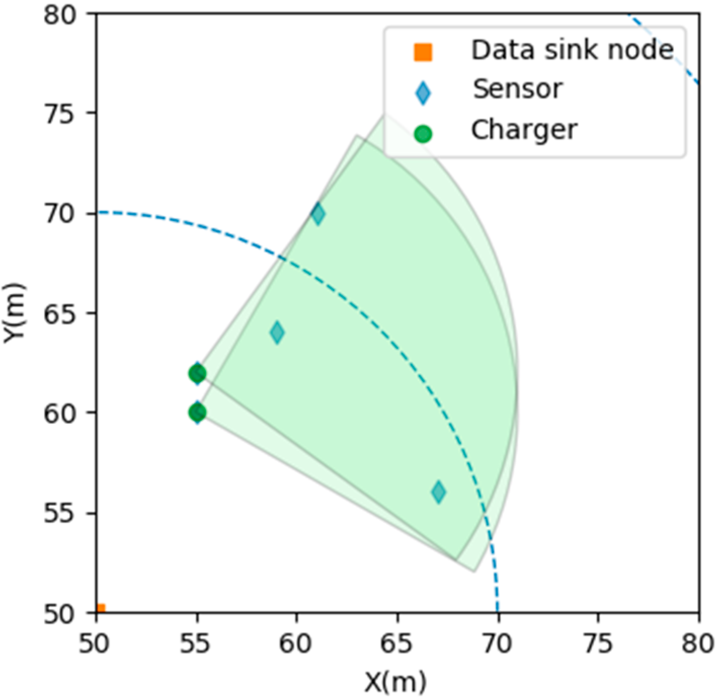
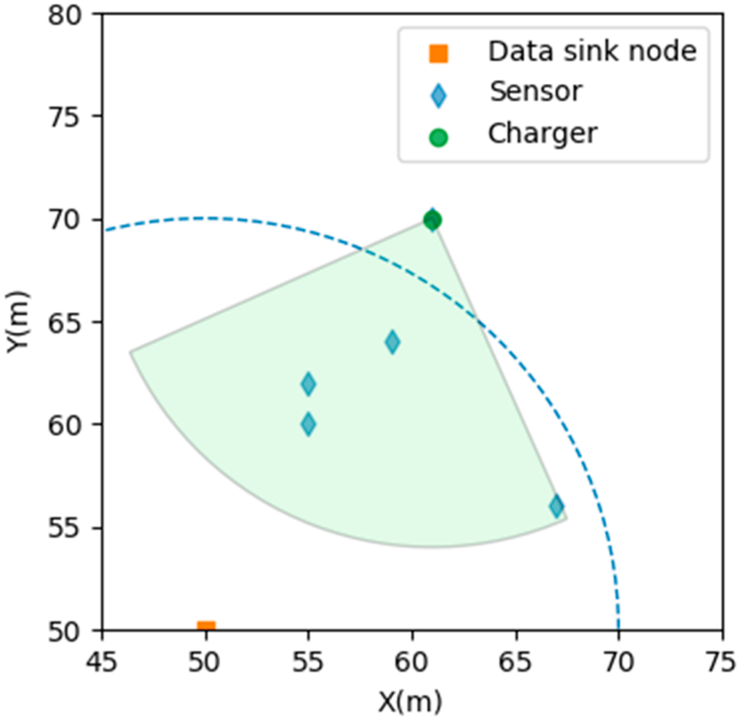
Input: The locations of all the sensors s i and directional charger c i
Output: Positions of chargers
1: Step 1. Randomly select the sensor position as the position of the charger.
2: Step 2. Search for the number of sensors covered by the chargeable radius d at charger position n.
3: while ( d i s t a n c e ( s i c i ) d ) do
4:  Record the number of sensors to n in the range.
5: end while
6: Step 3. The charger rotates 360° to find the angle that can cover most of the sensors within the charging range.
7: Step 4. If the number of sensors covered by Step 2 is more than three, Step 3 is repeated for different positions of sensors within the chargeable radius, and the position that covers most of the sensors is selected as the new position of the charger. If the number of sensors covered by Step 2 is less than three, the position of the charger does not change.
8: if ( n 3 ) then
9:  Search 360° and find the best angle that can cover most of the sensors;
10:  Record the number of covered sensors;
11:  Compare to the number of covered sensors of other chargers;
12:  Record the best charger location and the covered sensors in the range;
13: else
14:  Search 360° and find the best angle that can cover most of the sensors;
15:  Record the best charger location and the covered sensors.
16: end if
17: Step 5. Repeat Step 2 until all sensors are covered.
18: Step 6. Remove the excess charger positions in which the charger and the sensors covered by the charger can be covered by other chargers.
19: Search all locations of chargers and their covered sensors;
20: if (the charger location is redundant) then
21:  Remove the redundant charger location;
22: end if
23: return

3.3. An Example of SMRU

In this study, we use the sensor position to deploy a charger, which can ensure that the worst result of the position selection will converge to the number of sensors. This means that when there are N sensors in WRSNs, it is only necessary to deploy N chargers in the worst case. This can prevent the position selection algorithm from converging. The first idea at the beginning of this study is to search for the charger position that first covers the most sensors among all sensor positions. However, this method is time-consuming because the same calculation is repeated at 360° angles of the charger for each position. Therefore, this study improves the first idea. This study found that the key point to covering all sensors in WRSNs with fewer chargers is the charger position with dense sensors. For example, under the same sensor position configuration, if the charger position is selected as shown in Figure 1, the charge angle of the charger is limited, so that two chargers are required to fully cover all the sensors in this area. However, if the algorithm first compares the positions in the dense area and finds the position that can cover most of the sensors, the algorithm can reduce the number of chargers to one, as shown in Figure 2.
Therefore, the proposed algorithm first randomly assigns the position of the charger and then checks to see if there are more than three sensors in the 360° charging range of the charger, after which it selects the charger position that covers most of the sensors. If not, then directly select this position and find the best charging angle of the position to save the waste of repeated calculation time caused by the first idea. The reason for choosing more than three sensors in the charging range as the comparison standard is that if there are only one or two sensors that can be covered in the charging range, regardless of the selected position, the number of chargers in the charging range will not be affected. However, if the number of sensors that can be covered in the charging range is more than three, the results may be affected. As shown in Figure 3, if the algorithm selects the middle position, all sensors require two chargers. However, if the algorithm selects the two surrounding positions, it only needs one charger, as shown in Figure 4.
Finally, although the proposed algorithm minimizes the number of chargers required, experimental results show that extra chargers are required in some cases. The main reasons are the random selection of positions as a sequence of charger deployment, the comparison of the other candidate positions in the charging coverage area of the charger, and the selection of the best position from the candidate positions. As shown in Figure 5, if there are sensors that are arranged continuously, but the distance exceeds the chargeable radius, it cannot be applied to the proposed algorithm. Assume that there are four consecutive sensor positions arranged horizontally. If the order of the positions of the chargers is not appropriate, three chargers are required to fully cover all the sensors in this area. Therefore, this study improves the proposed algorithm again. After the initial selection of the charger position, it is necessary to check whether each charger and the sensors covered by each charger can be covered by other chargers. Assuming that the position of the charger fits this context, it means that the position of this charger is redundant. Therefore, after checking, remove the excess charger positions, as shown in Figure 6.

3.4. Sensor Mobility

In this study, we consider how the SMRU algorithm can change the position of chargers when the position of the sensors is moved. After the sensor moves the SMRU algorithm first confirms whether the number of sensors covered by the charger has changed. If the number of covered sensors decreases, the charger is rotated 360° to find the charging angle that can cover most of the sensors. If the number of covered sensors is unchanged or increased, the sensor data will be updated. Next, the SMRU algorithm examines whether there are any sensors in the WRSNs that are not being charged by any charger. If it is found that there are uncharged sensors, increase the chargers at the position of this sensor, and then rotate 360° to find the best angle that covers the largest number of sensors. Finally, the SMRU algorithm performs an optimization operation. If it finds an excess charger, it cancels the deployment at that position. The sensor movement was not considered in the PBAD algorithm. As PBAD does not have a mechanism for sensor movement, it needs to be recalculated when the sensors are moved, which takes twice as much time. However, the SMRU algorithm only needs to modify the position of chargers that are affected by sensor movement. Therefore, the modified execution time is much shorter than the original SMRU execution time. The algorithm is shown in Algorithm 2.
Algorithm 2 Changing the charger position after sensor mobility
Input: New locations of all sensors and original locations of chargers.
Output: New locations of all chargers.
1: Step 1. Check the number of sensors covered by each charger position n.
2: Step 2. If the number of covered sensors decreases, the charger is rotated 360° to find the charging angle that can cover most of the sensors.
3: if ( n <   original   covered   number   of   sensors ) then
4:  Search 360° and find the best angle that can cover most of the sensors;
5:  Record the best charger location and the covered sensors;
6: else
7:  Record the covered sensors;
8: end if
9: Step 3. Check if any sensor is uncharged.
10: Step 4. If it is found that there are sensors being uncharged, increase the chargers at the position of this sensor, and then rotate 360° to find the best angle that covers the largest number of sensors.
11: if ( the   sensor   is   not   charged ) then
12:  Add a new charger on the location of the sensor;
13:  Search 360° and find the best angle that can cover most of the sensors;
14:  Record the best charger location and the covered sensors;
15: end if
16: Step 5. Remove the excess chargers
17: if (the charger location is redundant) then
18:  Remove the redundant charger location;
19: end if
20: return

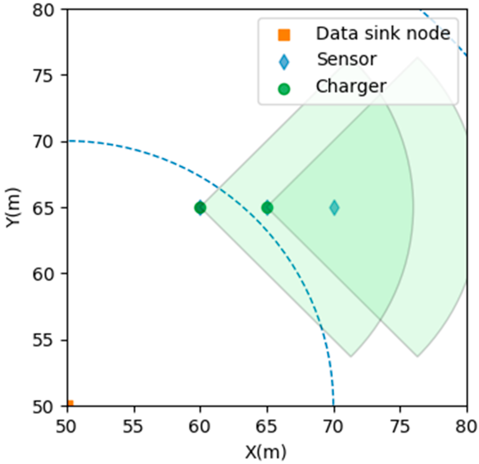
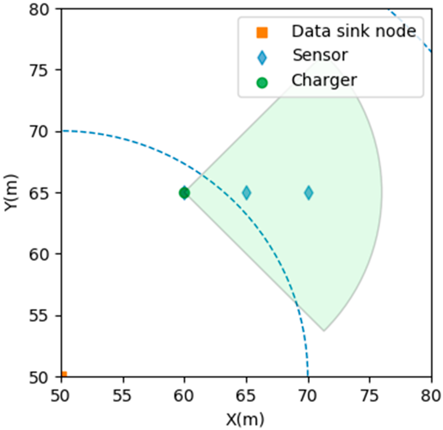
3.5. The Charging of Sink Nodes

The SMRU algorithm can calculate the energy consumption of the sink nodes. Under the premise of supplying enough energy to the sink nodes, the SMRU algorithm can reduce the number of chargers deployed to charge sink nodes. It also does not affect the number of chargers that need to charge sensors. First, the sensor will transfer the data to the sink that is closest to itself. After the SMRU has deployed the charger, it checks the amount of energy consumed by each sink. Next, the SMRU checks the charger within the charging distance of the sink and checks the number of sensors charged by the charger. If the number is equal to one, the charging angle is turned to sink. Therefore, the charger will charge one sensor and one sink. If the number of charging sensors is greater than 1, the charger rotates 360° again to search for the best angle, and the calculation includes the sink node. If the charging target can be covered more than the previous number (meaning that the previously charged sensors are covered; it also covers the sink node), the charging angle is updated; otherwise, the charger maintains the original charging angle. Finally, according to the energy that the sink still lacks, the SMRU deploys additional chargers around the sink to charge the sink. The number of chargers deployed can supplement enough energy as the minimum requirement. Consequently, all sink nodes can have enough power to receive the data sent by the sensor. The SMRU can make good use of the existing charger resources to charge the sink, so it can reduce the number of additional charger deployments. The algorithm is shown in Algorithm 3.
Algorithm 3 Charging energy of the sink nodes
Input: Locations of all sensors, locations of all chargers, and locations of all sinks
Output: Locations of new chargers
1: Step 1 Check how much energy is consumed by each sink.
2: Step 2. Find the charger, and if its distance from the sink node is less than the charging distance r.
3: Step 3. If the number of sensors n covered by the charger is greater than one, rotate 360° to check whether the charging of the sink node can be increased without affecting the originally charged sensors. If possible, update the angle of the charger. If not, maintain the original charging angle of the charger. If the number of sensors n covered by the charger is equal to 1, then the charging angle of the charger is turned to the sink node.
4: if ( n > 1 ) then
5:  Search 360° and find the best angle that can cover most of the sensors;
6:  Check whether the new covered number (ncn) is bigger than the original covered number (ocn);
7:  if   ( ncn > ocn ) then
8:   Record the new charging angle;
9:  end if
10: else if ( n = = 1 ) then
11:  Update charging angle;
12: end if
13: Step 4. Check the lack of energy for each sink node. Around the sink nodes, randomly select the position of the chargers to deploy the number of chargers needed to supplement the energy required by the sink nodes.
14: return

4. Experiments and Results

4.1. Experimental Environment and Parameters

In this study, a directional charger was used to conduct a simulation experiment. The experimental environment was to randomly generate sensor positions on a plane with a length of 100 units and a width of 100 units. The proposed algorithm was repeated 500 times to find the average result, and obtain the number of chargers and average execution time. As this study uses a directional charger, its related parameters are set to a chargeable angle of 90° and a chargeable radius of 16 units. Assume that the reception energy consumption of the sink node is 0.6 units/reception. The performance of the proposed algorithm is compared with that of the random position and random orientation (RPRO) and power balance aware deployment (PBAD) [10] algorithms using directional chargers.

4.2. Experimental Results of the Number of Chargers

This experiment compares the relationship between the number of sensors, different algorithms, and the number of chargers required. The average number of chargers used by the SMRU algorithm is less than that used by RPRO and PBAD. Figure 7 shows the average number of chargers used. RPRO selects the charger position and the charging direction randomly. As the charging angle is not selected, the number of chargers required is significantly large. PBAD searches for 360° angles that can cover most of the sensors for charging after randomly selecting positions. Additionally, PBAD repeatedly calculates the same sensor position map and selects the best position using a minimal charger as the deployment location of the charger. In this experiment, PBAD was repeated 10 times to select the best result. Therefore, the experimental results of PBAD are superior to those of RPRO. SMRU first selects a random position and then searches for 360° of the charging radius at that position. If there are more than three sensors (three candidate positions) within the charging radius at this position, it chooses the candidate position that can cover the largest number of sensors and deploy the charger. Additionally, the elimination of the excess charger positions that may be generated in the previous steps means that the number of charger requirements can be reduced to less than that of PBAD.

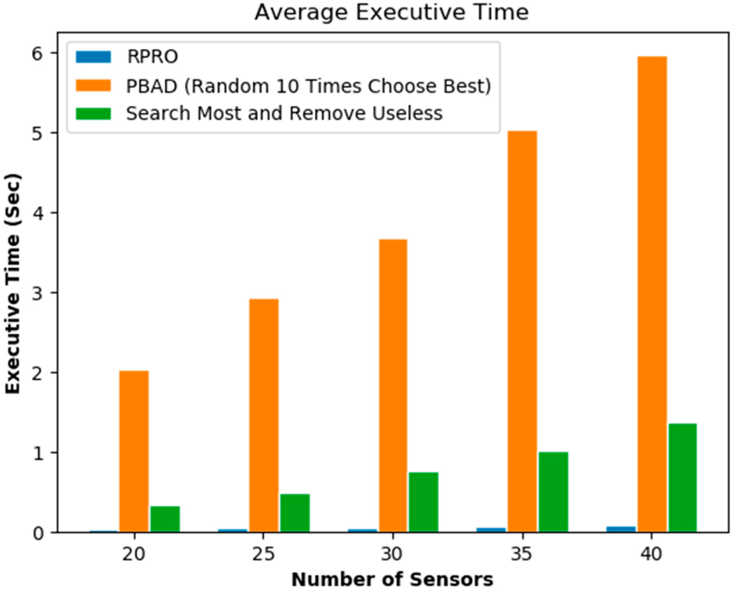
4.3. Experimental Results of Execution Time

This experiment compares the relationship between the execution time of different algorithms and the number of sensors. Figure 8 shows the average execution time. As the RPRO algorithm selects the position and charging direction of the charger randomly and does not have too many calculations, it requires little execution time. However, the number of chargers required by the RPRO algorithm is very large. The PBAD algorithm randomly selects the charger position and repeats the operation multiple times to obtain the best results. Although it can obtain good results, the iterative operations are performed multiple times. As a result, the average execution time is more than that of SMRU and RPRO, and the execution time will increase as the number of recalculations increases. When SMRU selects the position that covers the largest sensor, it decides whether to compare multiple positions. Only when the number of sensors (candidate positions) around the position is more than three will it be executed. This is because when the number of candidate positions is less than three, regardless of the position selected, it does not affect the coverage results, and thus can reduce the execution time of many repeated calculations. Additionally, the SMRU algorithm only needs to be executed once to obtain the results, and it is not necessary to repeatedly take the best value like PBAD. Therefore, the execution time performance is much better than that of PBAD.

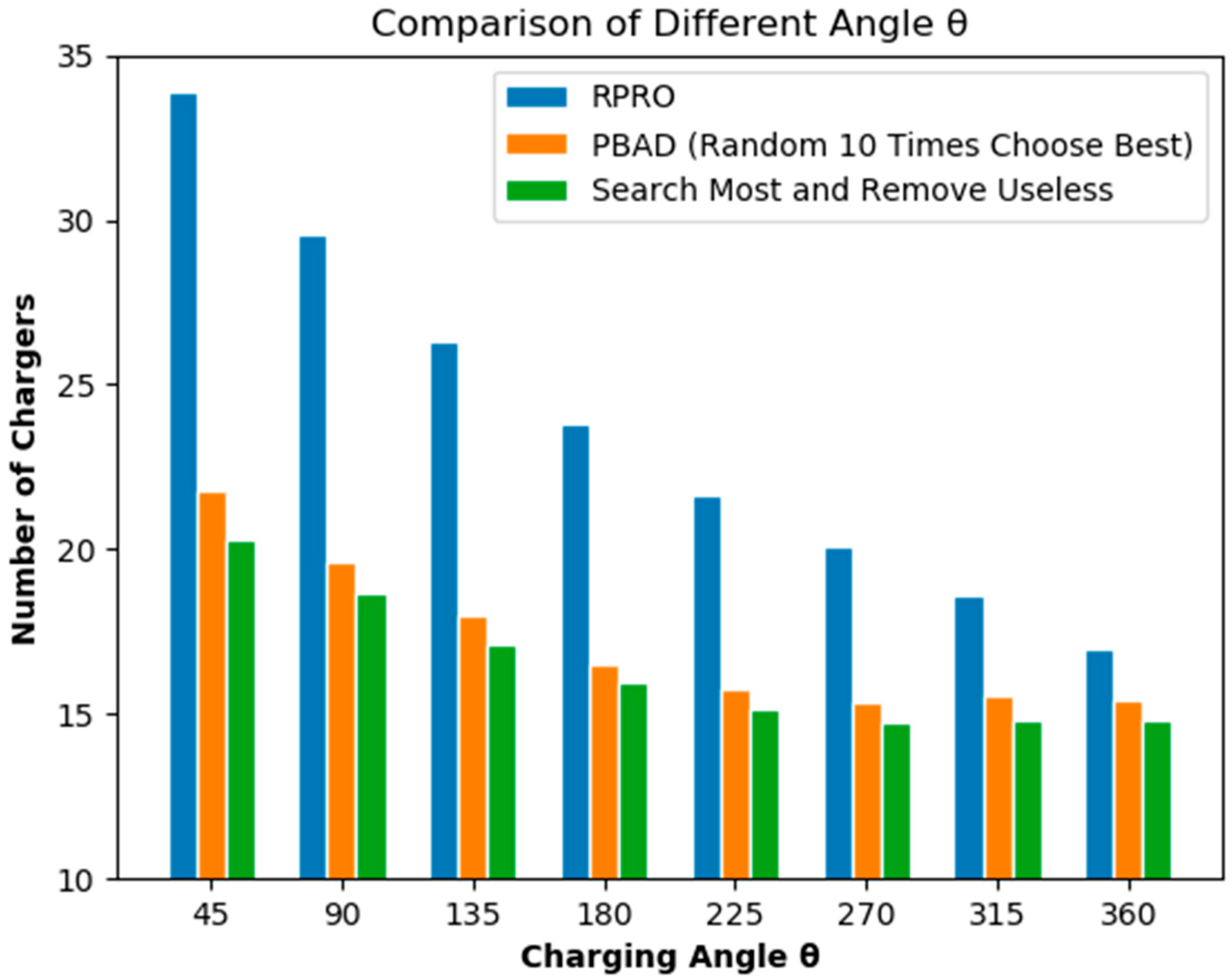
4.4. Experimental Results for Different Charging Angles

This experiment compares the relationship between the size of the charging angle and the average number of chargers. The experimental angle ranges from 45° to 360°. The RPRO, PBAD, and SMRU algorithms were tested separately. The charging radius is 16 units, and the number of sensors is 40. The experiment found that the larger the charging angle, the fewer the number of chargers required. The different charger requirements for different algorithms are as follows: SMRU has the smallest, followed by PBAD, and the worst is RPRO. Additionally, for the same parameter settings of the same algorithm, there seems to be a lower demand limit on the number of charger requirements. As shown in Figure 9, it can be observed from the experimental results that there is no significant difference in the average number of chargers after 270° between PBAD and SMRU. However, the difference is significant when the angle is smaller than 270°.

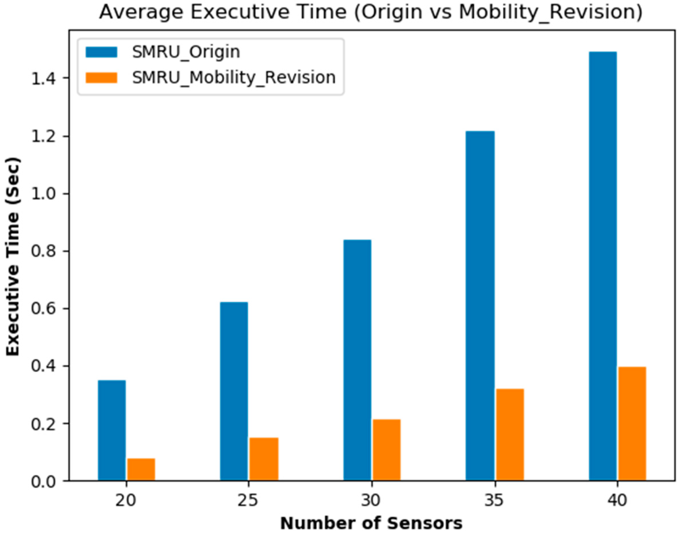
4.5. The Comparison of the Execution Time of Charger Deployment and Modified Deployment Using SMRU

In the experiment, we measured the execution time it takes for the SMUR algorithm to adjust the position of chargers after sensor mobility. After the SMRU selects the charger position, this experiment randomly moves the sensors from 0 to 2 units to simulate the movement of the sensors. A comparison of the execution time of charger deployment and modified deployment using SMRU is shown in Figure 10.

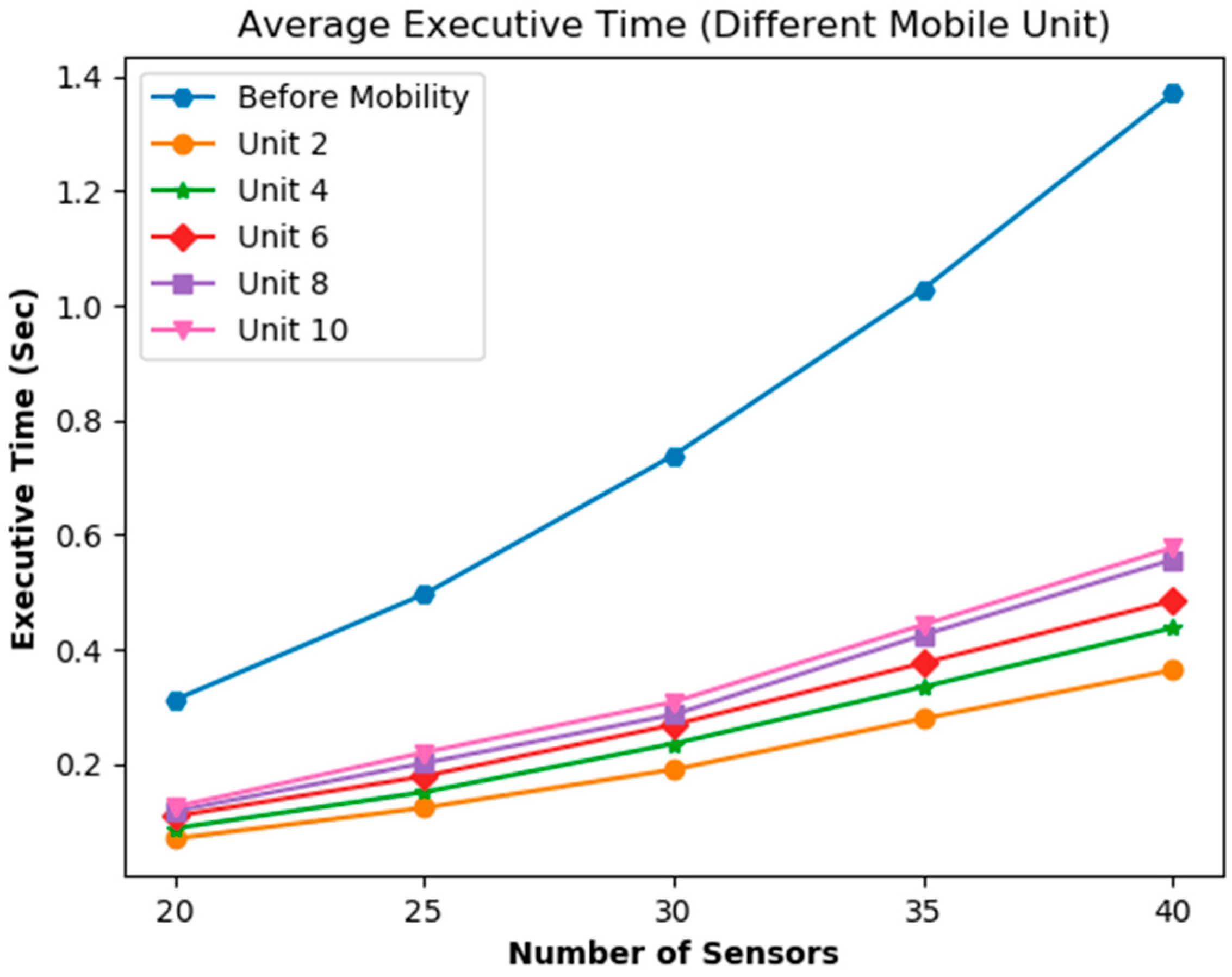
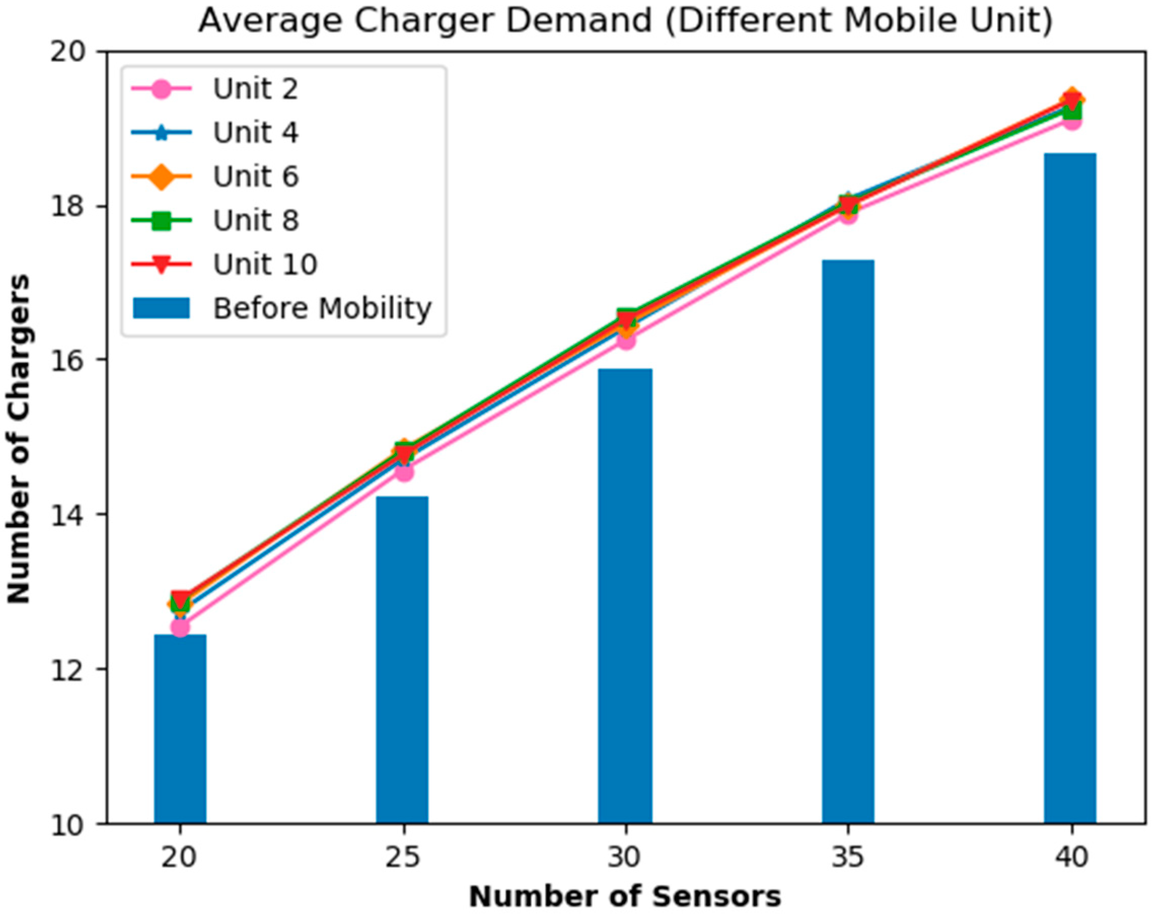
4.6. The Impact of Different Mobility Units

In this experiment, we first discuss the impact of different mobility units and average execution time for SMRU to adjust the position of chargers after sensor mobility. After the SMRU selects the charger position, this experiment randomly moves sensors from 2 to 10 units to simulate the movement of sensors. Due to SMRU does not recalculate the positions of all the chargers to find the global optimal solution after sensor mobility; it can reduce many execution times. The experimental results show that the execution time will increase with the number of sensors, and the increase in the mobility units of the sensor will increase the average execution time, as shown in Figure 11.
Next, we discuss the number of chargers used for SMRU to adjust the position of chargers after sensor mobility. Although SMRU does not recalculate the positions of all the chargers to find the global optimal solution after sensor mobility. However, the experimental results found that the number of chargers used does not increase too much after the sensor mobility. In addition, the number of chargers will increase with the number of sensors, and there is no obvious difference in the number of chargers used between different mobility units, as shown in Figure 12.

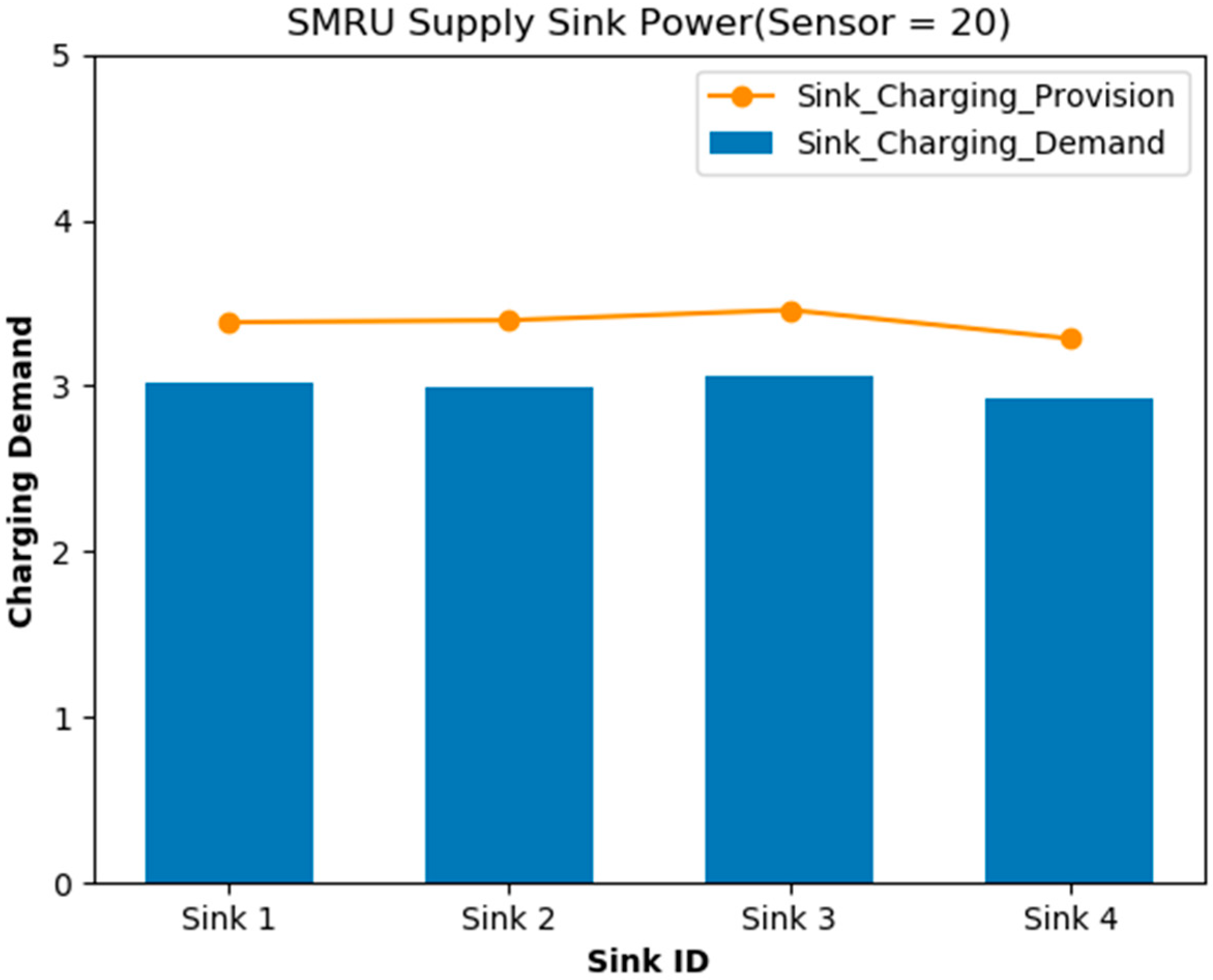
4.7. Energy Consumption and Supplementary of Sink Nodes with Different Sink Rates

In this experiment, we discuss how to deploy enough chargers with different sink rates. In the experiment, an average of four sink nodes (SN) were deployed in a 100 × 100 unit experimental environment, with coordinates SN_1 (25, 25), SN_2 (25, 75), SN_3 (75, 25), SN_4 (75, 75). As all sensors need to send data to the sink node, it is assumed that the radius of the received data of the sink is 36 units in the experiment to cover the entire experimental environment. Every time a sensor transmits data to the sink node, it increases the sink energy consumption by 0.6 units. Each charger can charge 1 unit of energy to the sink. The total number of sensors deployed in the experimental environment was 20. This experiment is based on being able to replenish all the energy needed by the sink nodes, and deploying enough chargers around the sink node to replenish the power. Figure 13 shows the energy consumption and supplementary of sink nodes with different sink rates.

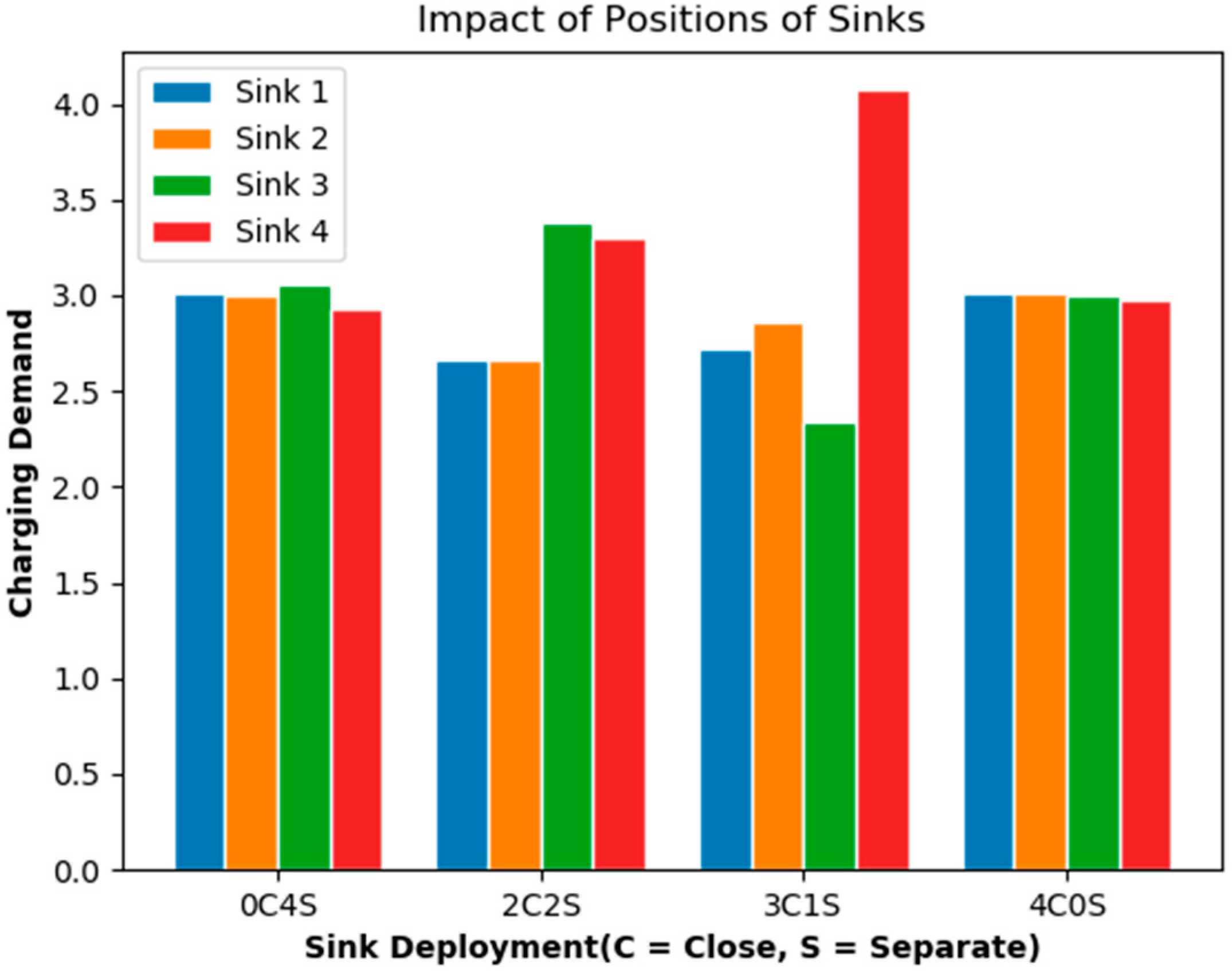
4.8. The Impact of Different Densities on the Energy Requirements of Sink Nodes

This experiment compares the impact of different densities on the energy requirements of sink nodes, as shown in Figure 14. This experiment deploys four kinds of sink node density. The first case is 4C0S (C = Close, S = Separate) representing four sink nodes that have overlapping coverage. The second case is 2C2S representing two sink nodes that have overlapping coverage (Sink 1, Sink 2) and two isolated sink nodes (Sink 3, Sink 4). The third case is 3C1S represents three sink nodes that have overlapping coverage (Sink 1, 2, 3) and one isolated sink node (Sink 4). The fourth case is 0C4S, which means four sink nodes are isolated. The positions of sensor nodes are randomly deployed in the coverage of sink nodes. The experimental results found that the average energy requirements of sink nodes is almost the same in 0C4S and 4C0S situation, as shown in Figure 12. In the case of sink nodes that have overlapping coverage, sink nodes can share the processing of sensor nodes in the same coverage, and so the energy requirements of sink nodes will be shared and reduced. Therefore, the average energy requirements of sink nodes are the same as the four isolated sink nodes. In 2C2S and 3C1S situation, some sink nodes have overlapping coverage and some sink nodes are isolated. As isolated sink nodes have no other sink nodes in the coverage to help process the data from sensor nodes in the coverage, this causes an increase in the energy requirements of sink nodes, as shown in Figure 14.

5. Conclusions

The deployment of WRSNs may require a large number of sensors. The use of fewer chargers in WRSNs to provide sufficient power for the sensors, reduce deployment costs, and maintain the operation of WRSNs is an important issue. Therefore, this study proposes an SMRU algorithm that uses fewer directional chargers to cover all sensors in WRSNs. In our proposed SMRU, the deployment position of the charger can be calculated in a short time, and all sensors in WRSNs are covered with a small number of chargers. Additionally, all sensor power is supplemented to avoid sensor interruption due to power consumption that causes WRSNs to fail and reduces the cost of deploying WRSNs. The performance of the proposed algorithm was compared with that of the RPRO and PBAD algorithms. Experimental results show that the average number of chargers used by the SMRU algorithm is fewer than that of RPRO and PBAD, and the execution time performance is much better than that of PBAD. In the future, we shall design a new algorithm that saves more chargers and computing time.

Author Contributions

Conceptualization, T.-L.L. and H.-Y.C.; methodology, T.-L.L. and H.-Y.C.; software, Y.-H.W.; validation, T.-L.L. and H.-Y.C.; formal analysis, T.-L.L.; investigation, T.-L.L.; resources, H.-Y.C.; writing—original draft preparation, T.-L.L. and H.-Y.C.; writing—review and editing, T.-L.L.; visualization, T.-L.L. and H.-Y.C.; funding acquisition, T.-L.L. and H.-Y.C. All authors have read and agreed to the published version of the manuscript.

Funding

This research was funded by Ministry of Science and Technology (MOST) of Taiwan, grant number 108-2321-B-415-003- and 109-2321-B-415-005-. MOST provided research funding and devices.

Conflicts of Interest

The authors declare no conflict of interest.

References

  1. Pantazis, N.A.; Nikolidakis, S.A.; Vergados, D.D. Energy-Efficient Routing Protocols in Wireless Sensor Networks: A Survey. IEEE Commun. Surv. Tutor. 2013, 15, 551–591. [Google Scholar] [CrossRef]
  2. Kausar, A.S.M.Z.; Reza, A.W.; Saleh, M.U.; Ramiah, H. Energy-Harvesting wireless sensor networks. Renew. Sustain. Energy Rev. 2014, 38, 973–989. [Google Scholar] [CrossRef]
  3. Sample, A.P.; Meyer, D.T.; Smith, J.R. Analysis, Experimental Results, and Range Adaptation of Magnetically Coupled Resonators for Wireless Power Transfer. IEEE Trans. Ind. Electron. 2010, 58, 544–554. [Google Scholar] [CrossRef]
  4. Global Wireless Charging Market 2016–2020. 2015. Available online: http://www.prnewswire.com/news-releases/global-wireless-charging-market-2016-2020-300196623.html (accessed on 31 July 2016).
  5. Gilbert, D. WiFi Routers Can Wirelessly Charge Batteries, Cameras and Sensors. 2015. Available online: http://www.ibtimes.co.uk/wifi-routers-can-wirelessly-charge-batteries-cameras-sensors-1504987 (accessed on 31 July 2016).
  6. Sendra, S.; Lloret, J.; Garcia, M.; Toledo, J.F. Power Saving and Energy Optimization Techniques for Wireless Sensor Neworks. J. Commun. 2011, 6, 439–459. [Google Scholar] [CrossRef]
  7. Liao, J.-H. Wireless Charger Deployment Optimization for Wireless Rechargeable Sensor Networks. In Proceedings of the 2014 7th International Conference on Ubi-Media Computing and Workshops, Ulaanbaatar, Mongolia, 12–14 July 2013. [Google Scholar]
  8. Horster, E.; Lienhart, R. Approximating optimal visual sensor placement. In Proceedings of the 2006 IEEE International Conference on Multimedia and Expo, Toronto, Canada, 9–12 July 2006. [Google Scholar]
  9. Ai, J.; Abouzeid, A.A. Coverage by directional sensors in randomly deployed wireless sensor networks. J. Comb. Optim. 2006, 11, 21–41. [Google Scholar] [CrossRef] [Green Version]
  10. Lin, T.L.; Li, S.L.; Chang, H.Y.J.E. A power balance aware wireless charger deployment method for complete coverage in wireless rechargeable sensor networks. Energies 2016, 9, 695. [Google Scholar] [CrossRef] [Green Version]
  11. Dai, H.; Liu, Y.; Chen, G.; Wu, X.; He, T.; Liu, A.X.; Ma, H. Safe charging for wireless power transfer. Tech. Rep. 2017, 25, 3531–3544. [Google Scholar] [CrossRef]
  12. He, S.; Chen, J.; Jiang, F.; Yau, D.K.Y.; Xing, G.; Sun, Y. Energy provisioning in wireless rechargeable sensor networks. IEEE Trans. Mob. Comput. 2013, 2, 1931–1942. [Google Scholar] [CrossRef]
  13. Chiu, T.C.; Shih, Y.Y.; Pang, A.C.; Jeng, J.Y.; Hsiu, P.C. Mobility-Aware charger deployment for wireless rechargeable sensor networks. In Proceedings of the 2012 14th Asia-Pacific Network Operations and Management Symposium (APNOMS), Seoul, Korea, 25–27 September 2012. [Google Scholar]
  14. Han, X.; Cao, X.; Lloyd, E.L.; Shen, C.C. Deploying directional sensor networks with guaranteed connectivity and coverage. In Proceedings of the 2008 5th Annual IEEE Communications Society Conference on Sensor, Mesh and Ad Hoc Communications and Networks, San Francisco, CA, USA, 16–20 June 2008. [Google Scholar]
  15. Garey, M.R.; Johnson, D.S. Computers and Intractibility: A Guide to the Theory of NP-Completeness; W. H. Freeman & Co.: New York, NY, USA, 1979. [Google Scholar]
  16. Mo, L.; Kritikakou, A.; He, S. Energy-Aware Multiple Mobile Chargers Coordination for Wireless Rechargeable Sensor Networks. IEEE Internet Things J. 2019, 6, 8202–8214. [Google Scholar] [CrossRef] [Green Version]
  17. Tang, L.; Guo, H.; Wu, R.; Fan, B. Adaptive Dual-Mode Routing-Based Mobile Data Gathering Algorithm in Rechargeable Wireless Sensor Networks for Internet of Things. Appl. Sci. 2020, 10, 1821. [Google Scholar] [CrossRef] [Green Version]
  18. Chen, J.; Yu, C.W.; Ouyang, W. Efficient Wireless Charging Pad Deployment in Wireless Rechargeable Sensor Networks. IEEE Access 2020, 8, 39056–39077. [Google Scholar] [CrossRef]
  19. Sumi, F.; Dutta, L.; Sarker, F. Future with Wireless Power Transfer Technology. J. Electr. Electron. Syst. 2018, 7, 2332-0796.1000279. [Google Scholar]
Figure 1. Covers all sensors with two chargers.
Energies 13 02661 g001
Figure 2. Covers all sensors with one charger.
Energies 13 02661 g002
Figure 3. Covers all sensors with two chargers.
Energies 13 02661 g003
Figure 4. Covers all sensors with one charger.
Energies 13 02661 g004
Figure 5. The position of this charger is redundant.
Energies 13 02661 g005
Figure 6. Remove the excess charger position.
Energies 13 02661 g006
Figure 7. The average number of chargers.
Energies 13 02661 g007
Figure 8. The average execution time.
Energies 13 02661 g008
Figure 9. The comparison results of different charging angles.
Energies 13 02661 g009
Figure 10. Comparison of the execution time of charger deployment and modified deployment using SMRU.
Energies 13 02661 g010
Figure 11. The impact of different mobility units and average execution time for search most and remove useless (SMRU) strategy to adjust the position of chargers after sensor mobility.
Energies 13 02661 g011
Figure 12. The impact of different mobility units and the number of chargers used for SMRU to adjust the position of chargers after sensor mobility.
Energies 13 02661 g012
Figure 13. The energy consumption and supplementary of sink nodes with different sink rates.
Energies 13 02661 g013
Figure 14. The impact of different densities on the energy requirements of sink nodes.
Energies 13 02661 g014
Table 1. Related deployment literature.
ResearchSensor or ChargerCharging TypeImportant ConceptsBalanced Battery Power Distribution
He et al., (2012) [12]ChargerOmnidirectional
  • Energy provisioning in WRSNs
  • Physical characteristics of wireless charging
No
Chiu et al., (2012) [13]ChargerOmnidirectional
  • Mobility-Aware charger deployment
  • Optimization of mobile deployment
No
Liao et al., (2013) [7]ChargerOmnidirectional
  • Optimized charger deployment for WRSNs
  • Sleep scheduling
No
Horster and Lienhart., (2006) [8]SensorDirectional
  • Approximating optimal visual sensor placement
  • Grid linear programming
No
Han et al., (2008) [14]SensorDirectional
  • Deploying directional sensor networks
  • Guaranteed connectivity and coverage
No
Lin et al., (2016) [10]ChargerDirectional and Omnidirectional
  • Power balance aware wireless charger deployment
  • Minimum dominating set problem
Yes
Mo et al. (2019) [16]ChargerOmnidirectional
  • The coordination problem among multiple mobile chargers
  • Mixed-integer linear programming problem
No
Tang et al., (2020) [17]ChargerOmnidirectional
  • Considering both charging and routing
  • Partitioned charging time according to the energy consumption
Yes
Chen et al., (2020) [18]ChargerDrone
  • A WRSN model equipped charging drone
  • The shortest multi-hop path problem
No

