Abstract
The presented paper dealt with the concept of an innovative manifold header for evacuated tube solar collectors. The proposed concept eliminates the drawbacks of conventional manifold headers, especially the serial connection of heat pipes that operate under uneven conditions. The advantage of the proposed design of the manifold header is also an increase in the heat exchange surface and the possibility of conducting the heat transfer media flow in a parallel flow arrangement, which increases the overall efficiency. The concept of the manifold header was evaluated on five variations of design with the use of the computational fluid dynamics (CFD) analysis. The results of the CFD analysis confirmed the functionality of the concept and also enabled the selection of the most suitable design elements, which were incorporated into the final design of a manifold header in the pre-prototype phase of manufacturing.
1. Introduction
Global environmental problems are becoming increasingly acute, which brings many challenges in various areas of human activities [1,2,3,4]. One of the solutions is the use of renewable energy sources, which are becoming an important and well-established part of the global energy mix. Of all types of renewable energy sources, solar energy has the greatest available technical potential. According to several studies [5,6], the technical potential is estimated to be between 1550 and 1600 EJ/year, which is approximately three times the global primary energy consumption with 550 EJ in 2019 [7]. Solar energy can be used in two main directions—for the production of electricity using photovoltaic panels or for the production of thermal energy using solar thermal collectors. The presented article deals with the use of solar energy utilizing evacuated tube solar collectors, which represent the top tier in solar collector technology and achieve the highest operating parameters in terms of operating efficiency or output temperature of the heated medium. This also makes them more and more widespread, whether in a home or in industrial applications.
The design of evacuated tube solar collectors may vary, but in principle, it is the use of the vacuum insulated absorption tubes that are connected to the manifold header. The vacuum tubes can be made of a glass cylinder with one or two walls, the vacuum can be in the whole inner volume or only in the space between the walls, the connection of the tubes to the manifold header can be directly serial or by means of so-called U-pipes; the surface of the solar absorber may have a rectangular shape or the shape of a curved cylinder surface. The state of the art evacuated tube solar collectors are discussed in [8,9]. In the most common type of evacuated tube solar collector, the vacuum tube is made of a double-walled glass cylinder in which a solar absorber with a heat pipe is placed. Between the glass tube is a vacuum, which eliminates heat loss. A heat pipe is a relatively simple device consisting of a vaporizing section in which the heat transfer medium evaporates, a transport section in which the vaporized medium flows centrally, and a condensation section where the vaporized medium condenses and releases heat, which is removed by heat transfer medium in the manifold header for further use. The condensed heat transfer medium flows along the wall of the transport section back to the evaporation section so the whole cycle is closed and carried over. The most commonly used is the serial connection, in which the tubes are connected in series, and the basic principle of how this works is shown in Figure 1. In this type of connection of evacuated solar tubes to the manifold header, it is necessary to take into account a certain degree of thermal resistance, which is caused by the contact of the heat pipe head with the housing, and by the interface of the heat transfer medium and the housing.
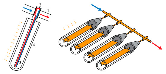
Figure 1.
Operating principles and essential parts of a conventional evacuated tube solar collector: 1—manifold header, 2—heat pipe head, 3—heat pipe, and 4—vacuum glass tube.
A large number of authors are currently engaged in the design and modification of the operating parameters of the evacuated tube solar collectors. Chopra et al. in [10] discussed the possibility of linking evacuated tube solar collector technology with suitable phase change material, which served as heat storage material. This connection improved the operational characteristics of the solar collector, but also eliminated the identified shortcomings in the form of low thermal conductivity of PCM and overheating of the heat pipes. Mercan et al. in [11] evaluated the use of nanofluids based on Al2O3H2O and CuOH2O, which were used as a heat transfer medium in an evacuated tube solar collector. Based on computational fluid dynamics (CFD) analysis and comparison, the authors confirmed that the use of CuOH2O had a significant positive effect on heat transfer. An interesting concept of using a concentration layer in an evacuated tube was presented in [12] by Teles et al. The new contributions from their work include the reflective film, the eccentricity of the absorber, and the presence of a vacuum in the annular space. The presence of a vacuum in the eccentric annular space effectively reduces the thermal losses and improves efficiency.
Another part of the authors dealt with hydraulic optimization of the arrangement of different parts of solar systems, solar collectors, or manifold headers. In document [13], the authors dealt with the non-uniformity of the flow distribution in the flat plate solar collector register. The analysis was solved utilizing CFD simulation. The authors evaluated four geometrical arrangements and suggested a solution for improving the flow uniformity by up to 40%. In paper [14], the authors investigated the flow through a forced circulation Z-type flat plate solar collector by means of combined experimental measurements and numerical simulations. The CFD-based procedure for enhancing flow rate uniformity among the risers was proposed and successfully demonstrated.
Based on the above review, it is clear that solar thermal technology has many areas that are suitable for the implementation of innovative solutions. When considering the presented type of the evacuated tube solar collector, the biggest shortage is, according to the authors, the commonly used serial connection of heat pipes, which brings several negative phenomena. The most important one involves uneven heat removal from each heat pipe head. This is due to a gradual increase in the temperature of the heat transfer medium in the direction of flow. The gradually heated heat transfer medium does not allow the same amount of heat to be drawn from each heat pipe head. This is caused by a gradual decrease in the temperature difference between the heat transfer medium and the heat pipe head. This phenomenon not only reduces the efficiency of the solar collector, but also worsens the lifecycle of heat pipes that do not operate at the same conditions during operation. A second significant drawback is the insufficient heat exchange surface between the heat pipe head and the heat transfer media, when, as is shown in Figure 1, the heat transfer medium only washes a portion of the heat pipe head.
All the above-mentioned shortcomings are solved by the proposed design of the manifold header of the evacuated tube solar collector. The proposed concept allows for the parallel connection of heat pipes in the manifold header and increases the heat exchange area. This paper deals with the five designs of manifold header and their mutual comparison in terms of hydraulic optimization using CFD analysis. The main task of CFD analysis and comparison was to eliminate the uneven division of flow in the manifold header as well as to suppress the formation of turbulent regions in the heat transfer medium.
2. Materials and Methods
The CFD analysis was conducted on five proposed designs and one commercially available design of the manifold header. Each of the evaluated manifold headers was created in CAD software as a 3D model of the inner fluid domain and heat pipe head housing, which was later imported in the Ansys Fluent where a CFD simulation was performed. From ParasolidXT geometry an unstructured tetrahedral mesh grid was created, with the number of cells ranging from 1,176,274 to 1,610,018 (depending on the manifold header variant). The fine mesh size function was used in the area where greater details were desired, such as a heat exchange chamber and coarse mesh function in areas of small changes in the domain. The boundary layer in the heat exchange chamber was modeled using an inflation function with growth rates of 1.2 and 5 layers. The maximum value of the skewness parameter was 0.624 with an average value of 0.227. An example of the mesh grid that was used can be seen in Figure 2.
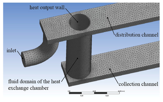
Figure 2.
Partial view of the mesh for the basic shape of the proposed manifold header and partial depiction of the boundary conditions.
The boundary conditions of the numerical simulation, such as mass flow rate and heat output, were determined concerning the basic parts and operating conditions of the commercially available evacuated tube solar collectors. All proposed designs of the manifold headers were developed for the double-walled glass evacuated tube that operates with a heat transfer medium mass flow rate of 13 kg/h/tube. Proposed designs consider the use of four evacuated solar tubes; therefore, all CFD simulations were conducted with a mass flow rate of 52 kg/h. The heat output that simulates the presence of a heat pipe head was applied to the inner surface of each heat exchange chamber, i.e., the inner wall of the annulus space. The value of the heat output was calculated corresponding to the intensity of the solar radiation of the 1000 W/m2 incident on the absorption area of the one evacuated solar tube with a value of 0.175 m2. After simplifying heat losses of the evacuated tube and local resistances in the manifold header, which have only a minor effect, the heat output of 175 W was applied to each area of the curved surface of a cylinder with a diameter of 14 mm and height of 70 mm (see Figure 2 and Figure 3). The heat loss from the surface of the manifold header body was simulated with heat convection of 5 W/(m2·K). Contact resistance was simulated with copper interface settings and a wall thickness of 1 mm. Boundary conditions are summarized in Figure 3.
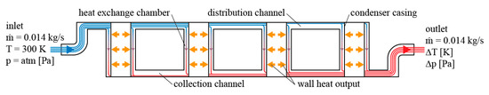
Figure 3.
Boundary conditions of the computational fluid dynamics (CFD simulation with a depicted representation of flow trajectories.
The calculation model was chosen based on the Reynolds number at the inlet location, the distribution, respectively collection channel, and in the heat exchange chamber. Based on the results, the viscosity model was set to k-epsilon RNG with a standard wall function. The pressure-velocity coupling was calculated with the use of the SIMPLE algorithm scheme. The solution converged at approximately 4500 to 5500 iterations (depending on the particular analyzed concept of the manifold header). The mathematical apparatus used by Ansys Fluent computational software is described in corresponding documentation [15].
The results of the CFD analysis were in the form of the temperature differences of the heat transfer medium at the inlet and outlet, pressure loss determination, and in the form of mapping of the temperature and the velocity of the heat transfer medium using contour plots. In 3D environment, turbulent kinetic energy was also visualized.
The comparison intentionally does not include a numerical CFD analysis of the efficiency curve of the solar collector according to EN 12975-2. In the case of using CFD tools, this evaluation represents a demanding task in terms of computational time or hardware power and would not be a beneficial contribution to the decision on the hydraulic optimization of the proposed manifold headers at this stage of the research of the proposed innovation.
The manifold headers were, thus, evaluated from the point of view of the efficiency of heat removal from the heat pipe head according to Equation (1).
where η is an efficiency of heat removal, ṁ is the mass flow rate of the heat transfer medium in kg/s, ∆T is temperature difference between the inlet and outlet temperature of the heat transfer medium in °C, c is the specific heat capacity of heat transfer medium in J/(kg·K), and Pout is heat output representing the presence of heat pipe heads; in the presented case, the heat output was 700 W.
η = (ṁ·c·∆T)/(Pout),
3. Results
As was mentioned above, the manifold header proposed by the authors allows the parallel connection of each heat pipe head in terms of conduction of the heat transfer medium flow, and it increases the heat exchange surface. In the present paper, five variants of the proposed manifold header and one commercially available manifold header, which served as a comparison (hereinafter referred as Case 0), are evaluated. A partial section view of a commercial manifold header is shown in Figure 4. This manifold header is composed of a copper tube with a length of 450 mm and an internal diameter of 26 mm, in which there are four through-going holes with a diameter of 16 mm. The heat pipe heads housings are made of 70 mm long tubes with an inner diameter of 14 mm.
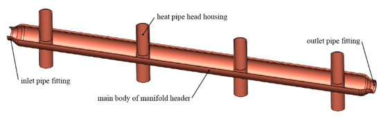
Figure 4.
Partial section view of the commercially available manifold header.
The shape and naming of the basic proposed design (hereinafter referred to as Case 1) are shown in Figure 5, where a view of the entire manifold header in isometric view, its longitudinal-section view, and its cross-sectional view can be seen. The essential element of the manifold header is a heat exchange chamber, formed by the annular space defined by the inside of the heat pipe head housing and the outside of the chamber housing.
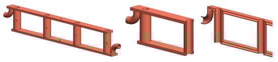
Figure 5.
The basic variant of the manifold header in isometric view (left), cross-section view (right), and longitudinal-section view (middle); 1—inlet pipe, 2—outlet pipe, 3—distribution channel, 4—collection channel, and 5 to 8—heat exchange chambers with inner heat pipe head housing pipe and outer chamber wall.
The dimensions are adapted to the real evacuated solar tube; the inner diameter of the annulus is 14 mm. The outer diameter of the heat exchange chamber is 20 mm, i.e., the thickness of the heat exchange chamber is 3 mm. The height corresponds to the height of the heat pipe head and is 70 mm. In this annulus, the heat transfer medium flows and is heated by the heat dissipation from the heat pipe head. In the evaluated variations of manifold header, four chambers were considered, but in real operation, it could be up to several dozen chambers. The spacing between the chambers is 120 mm. The heat exchange chambers are, in terms of flow, interconnected by a distribution and collection channel with a width of 20 mm and a height of 5 mm. The principle of the flow of the heat transfer medium in the manifold header is relatively simple. Low-temperature medium enters the collector through an inlet pipe with a diameter of 12.7 mm, and then flows into the distribution channel, where it is gradually segmented to each heat exchange chamber and flows in the annulus space. The temperature of the heat transfer medium increases in the heat exchange chamber. Then it flows into the collection channel and later through an outlet outside the manifold header body to the next part of the solar system. The conduction of the heat transfer medium at a 90° angle relative to the axis of distribution collection channel is based on the assumption of connecting the manifold header to the existing hydraulic circuit, where the inlet and outlet are axially symmetrical, as is the case with commercially available evacuated tube solar collectors. In an effort to commercially deploy a manifold header, one of its advantages would be the need to replace only the manifold header. The proposed manifold header would, therefore, be connected to existing hydraulic systems that have the inlet and outlet situated coaxially, which positively affects the entire exchange.
The evaluation of the concept was performed based on the mapping of selected parameters by CFD analysis. The result of this analysis was, among other things, the monitoring of the overall temperature increase of the heat transfer medium ∆T and the pressure drop in the manifold header ∆p. For a better representation of the flow and its basic parameters, maps of the flow velocity and distribution of turbulent kinetic energy throughout the manifold header, as well as a temperature map for each variant of the proposed design, were created. The manifold headers were also evaluated based on heat removal efficiency according to Equation (1).
The results of the CFD analysis of the basic design and commercially available manifold headers are depicted in Figure 6. The presented contour maps of the flow velocity and the temperature of the heat transfer medium confirmed the expectations regarding the improvement of the proposed manifold header compared to a conventional manifold header but also showed the areas with higher turbulent kinetic energy located behind the inlet, the inhomogeneous flow of the heat transfer medium in the heat exchange chambers, and the gradual heating of the heat transfer medium in the distribution channel, which causes insufficient heat removal from heat pipe heads and their uneven operation. Based on these findings, four modifications were proposed, which were designed with the intention to homogenize the flow of the heat transfer medium, improve heat dissipation, and ensure uniform operating parameters for each evacuated solar tube.
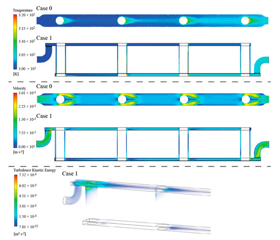
Figure 6.
Results of CFD analysis of the basic concept of the proposed manifold header (top—temperature contour map, middle—flow velocity contour map, bottom—3D visualization of turbulence kinetic energy).
The first change of the concept and, therefore, its second variant (hereinafter referred to as Case 2) is characterized by an adjustment of the distribution and collection channel in terms of its elongation before the first and last heat exchange chamber by 90 mm (compared to the previous solution, where it was 30 mm). This extension was introduced in an attempt to laminarize the flow before entering the first heat exchange. The third variant of the manifold header (hereinafter referred to as Case 3) is characterized by a change in the length of the heat pipe head housing, which is, in this case, ended in a way that does not interfere with the distribution channel. This reduction in the heat pipe head housing has also been introduced to reduce heating of the heat transfer medium in the distribution channel. The fourth variant of the manifold header (hereinafter referred to as Case 4) works with the idea of the diagonal conduction of flow, which is derived from the hydraulic principles commonly, used in non-segmented square-shaped flow channels in which the inlet and outlet are oriented at opposite ends. This arrangement is characterized by uniform flow conduction in the diagonal direction as is described in [16]. The introduction of this principle resulted in an extension of the distribution and collection channel by 10 mm in width and their offset from the centerline to opposite sides. These adjustments were introduced to improve the uniformity of the flow of the heat transfer medium in the heat exchange chambers. In the last modification (hereinafter referred to as Case 5), the dimensions of the distribution and collection channel were recalculated based on the continuity equation, which correlates volumetric flow rates, channel cross-section area, and flow velocity. The result is a channel that widens and narrows evenly from 22.5 mm to 5 mm, respectively, in a way that the sum of the cross-sections of both channels is the same at each point. The channel height was calculated according to the continuity equation to maintain the same flow velocity as in the inlet pipe while maintaining a width of 20 mm. The main modifications of each design are shown in Figure 7.
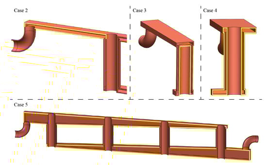
Figure 7.
Four basic designs with highlighted major changes from the basic concept.
Table 1 summarizes the basic elements of each variation of the proposed manifold header, the reasons for the modification, which were designed with regard to the identified shortcomings in the basic proposal according to results, observed in Figure 6 and the expected improvement of selected parameters in focused regions of the fluid domain.

Table 1.
The summary of the main feature of each modification and the expected results of their implementation.
Results of CFD Analysis of Proposed Modifications
Each of the modifications was evaluated based on the same parameters as for Case 0 and Case 1. For the sake of clarity, only those parameters and detailed views are presented and discussed, which evaluates the specific benefit of the modification. The left part of Figure 8 shows the partial view of the modification Case 2 with the elongated channel behind the inlet. From the 3D visualization of the turbulent kinetic energy, it can be seen that this modification largely eliminated the observed turbulence region as is depicted in Case 1. From this point of view, this modification can be considered successful, but when analyzing the temperature map in the right part of Figure 8, which shows the distribution channel, and the second and third heat exchange chamber, it is clear that there is the gradual heating of the heat transfer medium, which is undesirable.
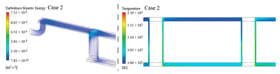
Figure 8.
3D visualization of turbulent kinetic energy in the region between the inlet and the first heat exchange chamber (left part of the figure), and a side view of the temperature field where the gradual heating of the heat transfer medium behind the second and third heat exchange chamber is visible (right part of the figure).
The modification Case 3, in which the heat pipe head housings are shortened, was designed precisely to avoid the above-mentioned gradual heating of the heat transfer medium. Because the housings do not interfere with the distribution channel, heat transfer from the housing wall to the heat transfer fluid is prevented. Figure 9 shows a 3D visualization of the temperature of the heat transfer medium in the distribution channel, where it is possible to see a uniform temperature in the entire distribution channel, but also unequal temperatures in the individual heat exchange chambers. It is clear that the first and last heat exchange chamber contributes to the heating of heat transfer medium to a lesser extent due to the unequal division of heat transfer medium flow to each heat exchange chamber.
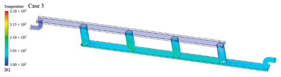
Figure 9.
3D visualization of the temperature field for the modification Case 3 where a uniform temperature is visible along the entire length of the distribution channel.
This inhomogeneity is solved by the designs Case 4 and Case 5, in which modifications directly affect the distribution and collection channel. Figure 10 shows a partial view of the heat exchanger without the inlet and outlet part. In the distribution and collection channel, it is possible to see the gradual separation or segmentation of the volume flow to each heat exchange chamber. This fact is evident from the gradual reduction or increase of the volumetric flow rate of the heat transfer medium. Concerning the continuity equation, this fact is evident from the gradual decrease or increase of the velocity flow rate of the heat transfer medium. However, behind each of the heat pipe heads, there is a place with a sudden decrease in the velocity flow rate, where the temperature rises (see bottom part of the Figure 10), which to some extent affects the other heat pipe heads.
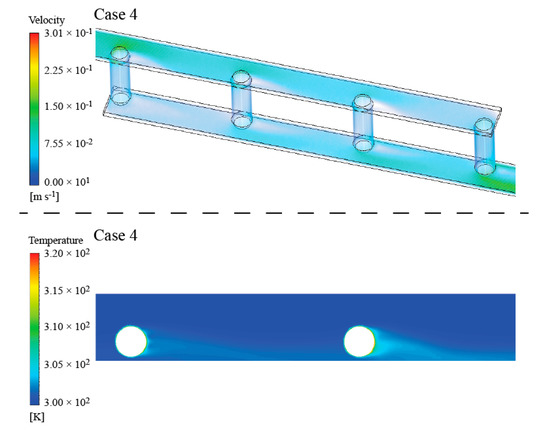
Figure 10.
Partial display of velocity flow rates (top) and temperature map in the distribution channel near the second and third heat pipe heads (bottom).
In the case of an effort to homogenize the flow in the heat exchange chambers, this modification represents a relatively successful solution. Similar results were achieved by the manifold header Case 5, where the modification involves changing the longitudinal cross-section of the distribution or collection channel. From the point of view of the homogenization of the flow through the individual heat exchange chambers, this modification achieves the best results, as is evident in the flow velocity map in Figure 11. However, when looking at the distribution channel, a high degree of heating of the heat transfer medium is already evident. This is due to the increase in the interface area between the flowing medium and the heat pipe head housings already in the channel. It is a negative fact because heat should be removed only in the fluid domain of the heat exchange chamber.
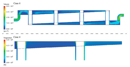
Figure 11.
Depiction of the velocity flow rates (top) and temperature map in the distribution channel (bottom).
The graphical results of the CFD analysis were also extended by numerical values quantifying the temperature increase, pressure drop, and efficiency of heat removal from the heat pipe head according to Equation (1). The numerical results are summarized in Table 2.
Table 2.
Temperature increase, pressure drop, and heat removal efficiency for evaluated designs of the proposed manifold header concept.
The overall CFD analysis shows that none of the variants reach satisfactory results in each monitored parameter. However, it can be said with a certain degree of confidence that the designs of Case 1 and 2 are not suitable from the view of flow homogeneity and temperature increase. Designs 3 to 5 achieve an improvement in terms of hydraulic optimization, which is particularly evident in the pressure drop, overall temperature increase in the heat transfer medium, or in the regions with decreased turbulent kinetic energy. From the point of view of the heat exchange process, the best values of the temperature difference and the heat removal efficiency are achieved by the Case 5. These good values have a negative consequence in the form of gradual heating of the heat transfer medium in the distribution channels and, thus, unequal working conditions of the individual evacuated solar tubes.
The result of the analysis shows that the best solution is to implement concepts 3, 4, and 5 into one design. The best concept seems to be a manifold header with a shortened heat exchange chamber and an elongated distribution and collection channel, which are offset and allow a better diagonal flow of the heat transfer fluid. However, the implementation of a gradual widening or narrowing of the flow channel, as described in Case 5, would also to a certain extent duplicate the effort to optimize the hydraulic conditions in the distribution collection channel. Another negative factor in the implementation of Case 5 is the increase in the internal fluid volume of the manifold header, which causes an increase in thermal inertia. This negatively affects operating parameters during a rapid change in solar radiation intensity during the intermittent cloud-covered sky. The resulting design, which suppresses the negatives and uses the positives of the presented modifications, is shown in Figure 12. The presented manifold header modifications increase the pressure loss to some extent, as is described in Table 2. This pressure loss is reflected in the increase of the pumping work and, thus, the necessary input of the circulation pump.
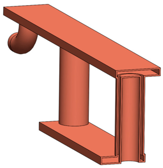
Figure 12.
Partial view of the 3D model with final design changes applied to the future manifold header prototype.
From the construction point of view, it is possible to manufacture the presented manifold header with relatively simple and available technologies and tools covering the entire spectrum from soldering to the use of hydroforming. In particular, the hydroforming technology appears to be a suitable tool. In one step, it would be possible to produce a channel of any cross-section with the connection of an inlet or outlet from one part. When connecting the heat pipe head housing or the outer wall of the heat exchange chamber, it is possible to consider soldering, pressing, or welding. The choice of material from which the manifold header could be made is based on commonly used materials in solar technology. The use of copper heat pipe head housing seems to be the most suitable, which will ensure a high value of heat transfer. Other parts are not problematic from the point of view of heat transfer and can be made of materials that have worse thermally-conductive properties. From a geometrical point of view, the only more serious requirement is the accuracy related to the coaxiality of the heat pipe head housing and the outer wall of the heat exchange chamber, where even the smallest deviation would mean a difference in the thickness of the heat exchange chamber. All presented manifold headers have been designed in a way that they can be easily manufactured with commonly available tools and prefabricated parts (pipes, fittings, etc.). This effort is based on the assumption of further direction of evaluation when it will be necessary to manufacture a manifold header prototype in the limited conditions of our research center in terms of instrumentation or material availability, and to conduct experiments and measurements in real operation.
4. Conclusions
The presented work dealt with the concept of an innovative manifold header for evacuated tube solar collectors. The proposed concept eliminates the drawbacks of conventional manifold headers, especially the serial connection of heat pipes that operate under uneven conditions, which deteriorates their lifecycle. The advantage of the proposed design of the manifold header is also an increase in the heat exchange surface and the possibility of conducting the heat transfer media flow in a parallel flow arrangement, which increases the overall efficiency of the device. In the presented work, CFD analysis of five variants of the manifold header was performed using Ansys Fluent software. Each of the five variants represented an evolution in terms of hydraulic optimization, considering the efficient heat removal from heat pipe heads and the existence of turbulent regions in fluid domain. CFD analysis verified the functionality of the concept and eliminated less suitable design variants. The results of the analysis were implemented in the design of an ideal manifold header that uses suitable design elements. The final design of the manifold header can be used as the basis for a prototype, which would be a suitable candidate for future physical experiments and measurements in real operating conditions.
Author Contributions
Conceptualization, M.B., R.R., M.C.; methodology, M.B.; validation, M.B., S.Z., P.S.; writing—original draft preparation, M.B.; writing—review and editing, M.B. and R.R.; visualization, M.B. and P.S., All authors have read and agreed to the published version of the manuscript.
Funding
This research received no external funding.
Acknowledgments
This paper was created in connection with the project KEGA: 067TUKE-4/2018—Creation of a laboratory of engineering creativity. Contribution is partial result of projects solving VEGA MŠVVaŠ SR 1/0515/18. The decisionmaking model of process of evaluating raw material policy of regions.
Conflicts of Interest
The authors declare no conflict of interest.
References
- Straka, M.; Cehlar, M.; Khouri, S.; Trebuna, P.; Rosova, A.; Malindzakova, M. Asbestos exposure and minimization of risks at its disposal by applying the principles of logistics. Przem. Chem. 2016, 95, 963–970. [Google Scholar]
- Jurkasova, Z.; Cehlar, M.; Khouri, S. Tools for organizational changes managing in companies with high qualified employees. In Production Management and Engineering Sciences-Scientific Publication of the International Conference on Engineering Science and Production Management; ESPM 2015–2016; CRC Press/Balkema: Tatranská Štrba, Slovakia, 2016; pp. 409–412. [Google Scholar]
- Khouri, S.; Pavolova, H.; Cehlar, M.; Bakalar, T. Metallurgical brownfields re-use in the conditions of Slovakia—A case study. Metalurgija 2016, 55, 500–502. [Google Scholar]
- Khouri, S.; Rosova, A.; Straka, M.; Behun, M. Logistics performance and corporate logistic costs, their interconnections and consequences. Transform. Bus. Econ. 2018, 17, 426–446. [Google Scholar]
- Kalaiselvam, S.; Parameshwaran, R. Thermal Energy Storage Technologies for Sustainability; Academic Press: Cambridge, MA, USA, 2014; pp. 8–10. [Google Scholar]
- Goldemberg, J. World Energy Assessment: Energy and the Challenge of Sustainability; UNDP: New York, NY, USA, 2000; pp. 12–18. [Google Scholar]
- Dudley, B. BP Statistical Review of World Energy; BP plc: London, UK, 2019; pp. 5–10. [Google Scholar]
- Evangelisti, L.; De Lieto Vollaro, R.; Asdrubali, F. Latest advances on solar thermal collectors: A comprehensive review. Renew. Sustain. Energy Rev. 2019, 114, 109318. [Google Scholar] [CrossRef]
- Siva Kumar, S.; Mohan Kumar, K.; Sanjeev Kumar, S.B. Design of Evacuated Tube Solar Collector with Heat Pipe. Mater. Today Proc. 2017, 4, 12641–12646. [Google Scholar] [CrossRef]
- Chopra, K.; Tyagi, V.V.; Pathak, A.K.; Pandey, A.K.; Saride, A. Experimental performance evaluation of a novel designed phase change material integrated manifold heat pipe evacuated tube solar collector system. Energy Convers. Manag. 2019, 198, 111896. [Google Scholar] [CrossRef]
- Mercan, M.; Yurddaş, A. Numerical analysis of evacuated tube solar collectors using nanofluids. Sol. Energy 2019, 191, 167–179. [Google Scholar] [CrossRef]
- Teles, M.; Ismail, K.A.R.; Arabkoohsar, A. A new version of a low concentration evacuated tube solar collector: Optical and thermal investigation. Sol. Energy 2019, 180, 324–339. [Google Scholar] [CrossRef]
- García-Guendulain, J.M.; Riesco-Avila, J.M.; Elizalde-Blancas, F.; Belman-Flores, J.M.; Serrano-Arellano, J. Numerical Study on the Effect of Distribution Plates in the Manifolds on the Flow Distribution and Thermal Performance of a Flat Plate Solar Collector. Energies 2018, 11, 1077. [Google Scholar] [CrossRef]
- Karvounis, P.; Koubogiannis, D.; Hontzopoulos, E.; Hatziapostolou, A. Numerical and Experimental Study of Flow Characteristics in Solar Collector Manifolds. Energies 2019, 12, 1431. [Google Scholar] [CrossRef]
- ANSYS Inc. Chapter 4: Turbulence. In Ansys Fluent Theory Guide; Ansys Inc.: Canonsburg, PA, USA, 2013; pp. 39–187. [Google Scholar]
- Bejan, A.; Lorente, S. The constructal law of design and evolution in nature. Philos. Trans. R. Soc. Lond. B Biol. Sci. 2010, 365, 1335–1347. [Google Scholar] [CrossRef] [PubMed]


© 2020 by the authors. Licensee MDPI, Basel, Switzerland. This article is an open access article distributed under the terms and conditions of the Creative Commons Attribution (CC BY) license (http://creativecommons.org/licenses/by/4.0/).