1. Introduction
The development of Carbon Capture and Storage (CCS) technology is justified by the potential of long term global climate change mitigation. The technology of injecting carbon dioxide (CO
2) into the rock medium has been known and used for many years and includes the EOR (Enhanced Oil Recovery) and EGR (Enhanced Gas Recovery) processes to intensify the extraction of oil and natural gas. The initiation of research on the possibility of CO
2 neutralization by its capture and storage in appropriately selected geological structures took place at the beginning of the 1990s [
1,
2]. The possibilities of CO
2 storage in geological formations are considered in the aspect of an adequate storage capacity of the geological structure, as well as the tightness and the integrity of the surrounding layers, which may constitute natural insulation of the potential storage site, and other aspects related to natural storage conditions or land management, which have a direct impact on maintaining the integrity of the site. In addition to the depleted hydrocarbon deposits (oil and natural gas), among the geological structures that may be used to store CO
2, there are also aquifers with high salinity and the unmineable coal seams. The issues regarding the selection criteria of the appropriate storage location have been widely described in both domestic and foreign literature [
2,
3,
4].
Before making a decision on the geological storage of CO
2, it is necessary to carry out an analysis of numerous criteria that determine the success of the process implementation from a technical, safety, ecological, and economic point of view. The criteria for selecting the storage site of carbon dioxide have not been clearly defined. The analysis of the international literature enables their division into groups of key factors such as (a) geological, (b) physical, thermodynamic, and hydrodynamic, and (c) techno-economic, safety, and social impacts [
3,
5,
6,
7]. The suitability of any particular site, therefore, depends on many factors, including the proximity to CO
2 sources and other reservoir specific qualities such as porosity, permeability, and leakage potential. For CCS to succeed, it is assumed that each reservoir type would permanently store the vast majority of injected CO
2, keeping the gas isolated from the atmosphere in perpetuity [
8].
In the case of the European Union, Directive 2009/31/EC of the European Parliament 2009/31/WE on the geological storage of carbon dioxide (CCS Directive) [
9] establishes legal framework for the geological environment of CO
2 storage. The purpose of the Directive is to ensure that the risks of CO
2 leakage or damage to health and the environment are kept to a minimum and, secondly, to prevent any adverse effects on the security of the transport networks or storage sites. According to the EC provisions, the Member States retain the right to determine the areas from which storage sites may be selected, including the right not to allow storage in any part of their territories [
10]. Based on the CCS Directive provisions, the characterization and assessment of the potential storage complex and surrounding areas have to be carried out in three steps according to the best practices at the time of the assessment and to the given criteria, i.e., (a) data collection, (b) building the three-dimensional static geological Earth model of the storage complex, and (c) characterization of the storage dynamic behavior, sensitivity characterization, and risk assessment. The assessment of the formations and structures suitable for safe CO
2 geological storage in Upper Silesia Coal Basin (USCB) has been mainly performed according to those provisions.
The geological structures for CO
2 storage must meet a number of criteria determining their suitability for this purpose. In the case of deep water bearing levels, these should be brine formations. According to the hydrogeological classification of mineral waters used in Poland, brine waters are waters with a mineralization exceeding 35 g/dm
3 [
10] whose main components are dissolved ions such as chloride, sodium+, and calcium Ca
2+. In addition, some authors distinguish a group of strong brines with a mineralization above 150 g/dm
3 [
11]. The key criterion is also the presence of an impermeable overburden, which is to ensure proper insulation of the tank. The structure intended for CO
2 storage should also be located below the drinking water aquifers. When choosing the right location, one should also take into account the occurrence of aquifers and mineral deposits that may be operated in the future [
12]. The basic criteria for selecting the geological structure to store CO
2 [
2,
5] are total storage capacity (greater than the total CO
2 production expected by the issuer to be stored), the depth of the geological formation (from 1000 m to 2500 m), thickness (over 50 m), porosity (over 20%), permeability (over 300 mD), salinity (over 100 g/dm
3), the thickness of the overburden (over 100 m), and the lack of faults. However, such criteria are used for the general and the preliminary classification of a geological formation in terms of its suitability for CO
2 storage. It should be emphasized that the selection of the appropriate location must be preceded by a series of additional tests and analyses taking into account the specific conditions.
The storage of CO
2 in geological formations involves the risk of uncontrolled release of the gas outside the reservoir, which may be, among others, the result of the permeation of CO
2 through the geological structure layers. An analysis and assessment of the geological hazard of CO
2 storage must take into account all possible migration paths, depending on petro-physical and thermodynamic conditions, as well as technical solutions used in the design and the implementation phase to prevent and monitor this threat [
13].
One of the most serious hazards resulting from the geological storage of CO
2 in brine formations is the hazard related to the potential escape of CO
2 through discontinuities or loosening rocks in the reservoir overburden, which may pose a threat to the health and safety of people, the natural environment, natural resources, especially water bearing levels of drinking water, or surface infrastructure [
14,
15,
16]. It should be emphasized that the lack of or incorrectly carried out assessment of the hazard of CO
2 leak may generate future costs associated with the need to take preventive and corrective actions. Thus, one of the key elements of CO
2 storage security in geological formations is the proper identification, characterization, and assessment of the hazard of CO
2 leak and its potential consequences. According to the Directive on the geological storage of CO
2, the hazard analysis in this case should be carried out at each of the CO
2 injecting stages, and the safety analysis should include the issues of public health and safety, the environment, and natural resources. It should be noted that the hazard assessment methods used so far in many global and European geological CO
2 storage projects are mainly methods based on the qualitative description of the frequency of emergency events, as well as their range and effects [
17,
18,
19]. The reasons for using this type of method result primarily from the lack of sufficient numerical data. More precise methods began to be used along with the development of research and results obtained from the storage sites of CO
2. The most common methods used here are the Fault Tree Analysis (FTA), the HAZOP (Hazard and Operability Study) method, or the Event Tree Analysis (ETA) [
20].
The development or the adaptation of the existing methods for geological risk assessment of CO
2 storage has become a research issue only recently. The need for further development of these methods has been repeatedly indicated both in world and national literature [
21,
22,
23]. This applies in particular to the following two aspects:
risk assessment for long term storage of CO2 in the perspective of thousands of years,
risk assessment results to be used in social acceptance programs.
The difficulty of developing such assessments is primarily caused by the specificity of the CO2 storage problem whose characteristics and evaluation are based on dynamic modelling, including a series of time simulations of the CO2 injection process. The nature of hazards may change during various phases of the injection process, as well as the subsequent behavior of the stored CO2. This may result, for example, from the nature of CO2 flow in the reservoir, cracking speed, occurrence of seismic activity, pressure and temperature changes in the rock formation, changes in the chemical composition of the formation fluid and possible subsequent reactions (e.g., pH change, mineral composition), as well as the emergence of new mineral substances as a consequence of the storage of CO2.
The paper presents an analysis of the possible location of the geological formations for CO2 storage in the Upper Silesia Coal Basin, Poland. The analysis of the technical and geological possibilities of CO2 storage was carried out according to the regulations of the complex Polish geological law. The possibilities of CO2 sequestration in geological formations were investigated.
3. Results and Discussion
3.1. Conceptual Geological Model and Numerical Modelling of the Bielsko Reservoir, Poland
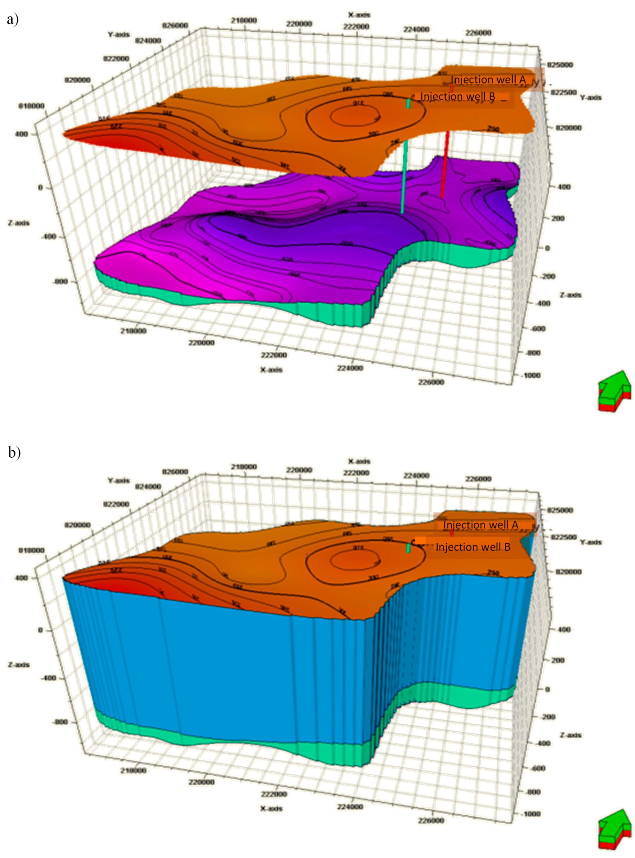
The conceptual model of the Bielsko reservoir was developed on the basis of geological data from 73 geological profiles. In the model, simplifications were made based on the presentation of overburden layers consisting of the Skawina formations and the Carpathians over-thrust in the form of a single layer. This simplification was introduced after a thorough analysis of the geological, hydrogeological, and petrographic properties of these formations (see
Figure 2). This simplification did not affect in any way the results of further research and simulations of the CO
2 spread in the site.
The dynamic modelling of the CO
2 distribution in the aquifer was carried out on the basis of the TOUGH2 simulator of the PetraSim v.5 software. It allowed simulating the flow of single and multi-phase isothermal and non-isothermal fluids, enabling the simulation of multi-phase flows, including the phenomena of adsorption and diffusion. The simulator uses the finite difference method (the Integral Finite Differences formulation (IFD)) [
30,
31,
32]. For further considerations, the ECO2N co-processor was used allowing modeling the injection of CO
2 into geological structures. This flooding is a complicated process due to the physical and chemical properties of the gas, which directly translates into considerable difficulty of carrying out the dynamic modelling of this process. The Tough2/ECO2N module allows modelling of non-isothermal flows of multi-phase water-brine-carbon dioxide systems. The chemical reactions presented in the ECO2N module include the equilibrium stage between water and carbon dioxide, i.e., between the liquid and gas phases, whereas between CO
2 and H
2O (between the gas and liquid phases, respectively), this equilibrium is represented as a function of temperature, pressure, and salinity, using the correlation according to Pruess and Spycher [
33]. The decomposition and solubility of the salt are treated in the ECO2N module by means of local equilibrium solubility. Taking into account the changes in the porosity and permeability of the medium, all phases, i.e., gaseous, liquid, and solid, may appear or disappear in the grid of the considered block during the start of the numerical simulation.
The dynamic model of the CO2 distribution in the Bielsko site covered within its scope an area of approximately 1750 km2. The main goal of the dynamic model was to present graphically the process of CO2 injection to the site with a 30 year time span, as well as its distribution in the structure within 200 years after the completion of the injection. The completed models also allowed presenting the processes taking place in the site during the operational and post-operational phase, i.e., after closing the site, while taking into account the potential migration of CO2 in the case of escape from the reservoir.
Both in the conceptual models and in the dynamic modelling, all previously analyzed data, including the presence of geological holes in the analyzed area, were taken into account. Approximately 130 old boreholes are located in the analyzed area and its immediate vicinity. In the location of the CO
2 Storage Reservoir 4, boreholes were drilled to the Bielsko reservoir [
4]. The data regarding these holes in terms of their depth and the technologies of their elimination were analyzed (see
Figure 3). Some of the openings were deeper than those of the Dębowiec layers, which meant that they were overly drilled, and the same may affect the safety of CO
2 storage (see the holes marked as yellow points in
Figure 3a). The holes that did not reach the Dębowiec layers were marked with red crosses. Additionally, as part of the implementation of the research, field work was carried out to check the location of boreholes and the state of liquidation. These works allowed identifying leaks in one of the analyzed holes, which was taken into account in further work, including the modelling of CO
2 spread in the structure. Moreover, the impact of the “Dębowiec Śląski” and “Pogórz” natural gas fields being operated near the site was also investigated. Within the fields, there are 26 demolition holes and 9 open plumbing holes, along with 3 service openings, the depth of which ranges from about 530 to 1250 m. In order to map the physical properties of the model, four layers were distinguished due to their different parameters. The impermeable layers of Miocene and Carpathian overthrust, forming the site overburden, were presented in the form of one layer marked in the model as “ABOVE”. The Dębowiec layers, because of their different permeability and porosity, were additionally divided into five rock layers from DEB1 to DEB5 (see
Figure 3b), whereas Carboniferous formations constituting the roof of the site were referred to as “CAR”. The physical parameters of the discussed rock layers are presented in
Table 1.
In order to simulate the sequestration processes, the ECO2N module of the TOUGH2 simulator was used. A three component mass balance was assumed (H2O, CO2, and NaCl). The initial conditions adopted in the model were as follows:
Pressure at the injection spot: 10.75 MPa
Temperature: 36 °C
Salinity: 20 wt.% NaCl
Saturation with carbon dioxide: 0.0
Enthalpy: 270 kJ/kg
Thickness of the aquifer: 57 to 170 m.
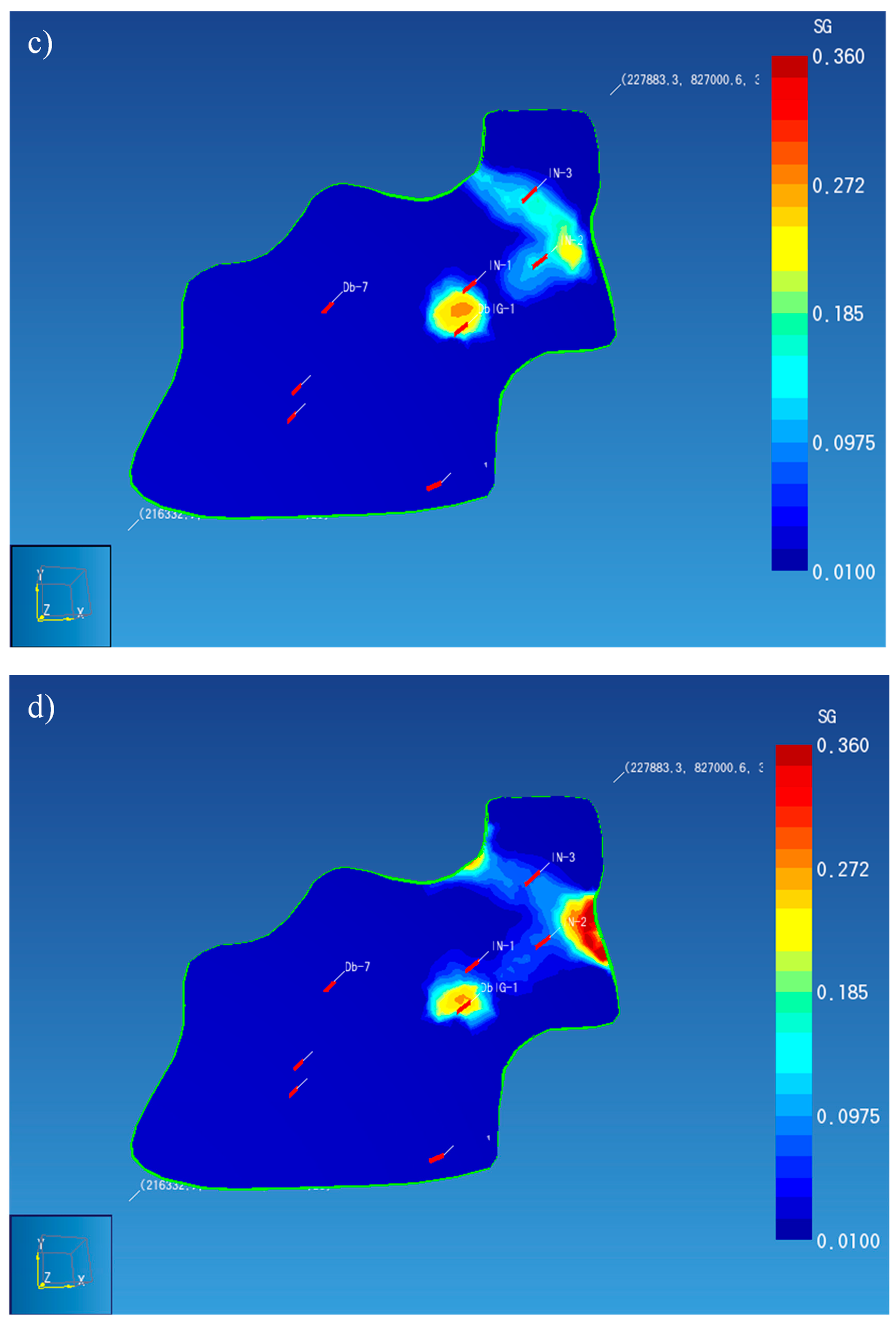
In order to determine the safety of the location, it was assumed that CO
2 would be injected in the amount of 300,000 Mg per hole per year, for a period of 30 years. Based on the value of gas saturation of the roof layer at the hole, as well as the time of reaching the clouds of CO
2, the time after which the carbon dioxide would start to escape to the surface was determined for the analyzed untight hole DbIG-1. The time for the cloud to reach the hole was about 27 years, while the time of gas escaping to the surface was 120 years.
Figure 4 presents the saturation of CO
2 in the roof of the Dębowiec layers at specific time periods.
The simulation also allowed determining the time after which the cloud reached the boundaries of the designated reservoir. The simulation and its initial assumptions were based on geological criteria defined during the implementation of the project under Initiative I. The escape of gas from the site through inactive boreholes constituted a very important issue in the assessment of the geological risk of CO
2 storage. In
Figure 5a, a 3D view of CO
2 discharge to the surface along with the approximate spreading distance of the cloud on the surface are presented.
The proper identification of the geological structure for CO
2 storage is crucial due to the safety of the process. However, this is not the only condition that minimizes the risk of CO
2 escapes. In addition to the exact characteristics of the selected geological formation along with the tightness assessment of its overburden, as well as considering the mechanism of the geological storage of CO
2 and the course of possible chemical reactions of gas with brine and the surrounding rocks, it is also necessary to take into account the course of the injection process, i.e., the rate of CO
2 injected and the potential geo-mechanical effects [
29]. For the purpose of geological hazard assessment, it seems justified to apply a series of simulations based on numerical modelling of gas distribution in a selected structure. Based on the obtained modelling results, the distribution range of CO
2 in the geological structure was determined. The range should be the basis for safety analysis and the identification of vulnerable zones with potential CO
2 escapes. For this purpose, additional research is necessary taking into account the characteristics and the analysis of the surface area located above the CO
2 storage complex. The analyses should include, among others, land morphology, anthropogenic activity, and climatic conditions in order to determine the possibility of dangerous events associated with possible CO
2 leakage from the site and to evaluate their potential impacts.
3.2. Carbon Dioxide Storage in Geological Formations within the Context of Polish Legislation
Viewed from the perspective of current technological development, carbon dioxide is perceived almost exclusively as waste. Within the framework of Polish legislation, the concept of waste was set out in the Act of 14 December 2012 On Waste (consolidated text of 15 March 2019 Journal of Laws of 2019, Item 701), hereafter the Act on Waste. The legislator defined waste as any substance or object that the holder discards or intends to or is required to discard. The central objective of the said Act is to lay down measures to protect the environment and human health by preventing or mitigating the adverse impacts of the generation and management of waste, as well as by reducing the overall impact of resource use and increasing the efficiency of such use. The above regulation, however, does not constitute a comprehensive legal coverage of the issue of waste generation and management. The legislator singled out a few exceptions, in the case of which the provisions of the Act do not apply. CO2 designated for underground storage in order to execute a CCS demonstration project as stipulated by the Geological and Mining Law Act of 9 June 2011, Article 1, Item 3, (consolidated text of 4 April 2019, Journal of Laws of 2019, Item 868), hereafter referred to as the Mining and Geological Law, constitutes such an exception. According to Article 1, Item 3 of the Law, a demonstration project of carbon dioxide capture and storage is understood as a project consisting of capture, conveyance, and underground carbon dioxide storage. Such a project is required to meet the criteria for demonstration projects set out in Commission Decision No. 2010/670/EU of 3 November 2010, laying down the criteria and measures for the financing of commercial demonstration projects encompassing environmentally safe CO2 capture and geological storage, as well as demonstration projects of innovative renewable energy technologies under the scheme for greenhouse gas emission allowance trading within the Community established by Directive 2003/87/EC of the European Parliament and of the Council (OJ L 290, 6 November 2010, p. 39). Such projects may be implemented for the purpose of verifying: (a) the effectiveness and usefulness of the application of the CCS technology within the scope of reducing carbon dioxide emissions; (b) the safety of applying the CCS technology in terms of human health and life, as well as the environment; (c) the need and grounds for an industrial scale application of the CCS technology.
It is worth mentioning that the exclusion of carbon dioxide designated for underground storage in order to execute a CCS demonstration project as stipulated by the Geological and Mining Law from the provisions of the Act on Waste (Article 2, Point 12) was introduced by the Act of 27 September 2013 on the Changes of Geological and Mining Law (Journal of Laws of 2013, Item 1238), effective as of 24 November 2013. Simultaneously, the said Act made also changes in the objective scope of the Geological and Mining Law, introducing the issue of underground storage of carbon dioxide in order to execute a CCS demonstration project.
The Polish legislator imposed regulations and administrative control of activities connected with underground carbon dioxide storage. Thus, the provisions of the Geological and Mining Law stipulate that this kind of activity requires a concession. It is worth stressing that the underground storage of carbon dioxide was permitted exclusively for the purpose of executing a CCS demonstration project. The Geological and Mining Law introduces a ban on any activities consisting of the exploration or recognition of a subsurface storage complex or of underground carbon dioxide storage for any purpose other than a CCS demonstration project. The period for which the concession for underground carbon dioxide storage was granted should take into consideration the obligation to monitor the underground storage complex for a period no shorter than 20 years following the closure of the storage site.
The concessions for prospecting for or exploring an underground carbon dioxide storage complex, as well as for underground carbon dioxide storage are granted by the Minister in charge of the environment. In addition, prior to applying for the concession for underground carbon dioxide storage, it is necessary to obtain an opinion from the European Commission. The basic prerequisites required to obtain the said concession are the following: (a) evidence of the ownership right or the right of perpetual usufruct of the land where the mining plant and, in particular, the injection facility and the installation monitoring the underground carbon dioxide storage complex are to be located; (b) establishing financial collateral securing the due performance of the obligations resulting from the operation of an underground carbon dioxide storage site and the decommissioning of a mining plant.
The purpose of establishing the financial collateral that secures the due performance of the obligations resulting from the operation of the underground carbon dioxide storage site is to make sure that the conditions specified in the concession are met. In particular, the collateral is to secure the costs of monitoring the underground carbon dioxide storage complex, as well as the costs of corrective measures, emission accounting in the case of carbon dioxide escape from the storage complex, and the costs of corrective and preventive measures within the meaning of the provisions of the Act of 13 April 2007 on the Prevention and Remediation of Environmental Damage (consolidated text of 30 August 2019, Journal of Laws, 2019, Item 1862; hereafter referred to as the Act on the Prevention and Remediation of Environmental Damage), as well as the compensation for losses that emerged before the closure of the underground carbon dioxide storage site.
The financial collateral securing the due performance of the obligations connected with the decommissioning of an underground carbon dioxide storage is supposed to guarantee the coverage of costs related to the removal of the mining plant facilities, the decommissioning of wells and other installations connected with the underground carbon dioxide storage site, including pipelines, cables, and power lines, the costs of monitoring of the closed underground carbon dioxide storage site for a period not shorter than 20 years as of the day of its closure, the costs of corrective measures, emission accounting in the case of carbon dioxide escape from the underground carbon dioxide storage complex, the costs of corrective and preventive measures within the meaning of the provisions of the Act of 13 April 2007, as well as the payment of compensations for the losses that emerged after the underground carbon dioxide storage site has been closed.
The concession for underground carbon dioxide storage specifies in particular the following aspects: (a) the type and scope of the intended activities; (b) the space within the boundaries of which geological works are to be performed; (c) the period of validity of the concession; (d) the quantity and characteristics, including the source of origin, of carbon dioxide to be injected into the underground storage site; (e) the volume of the permitted carbon dioxide stream to be injected into the underground carbon dioxide storage site; (f) information concerning the hydro-geological unit understood as part of a lithosphere constituting a spatial and dynamic groundwater circulation system that can be described with hydro-geological parameters of aquifers and semi-permeable formations that separate them; (g) the pressure limit in the underground carbon dioxide storage complex; (h) injection efficiency and pressure under which carbon dioxide is injected into the underground storage site; (i) the scope and method of monitoring the underground carbon dioxide storage complex; (j) the minimum value of the security deposit for the fulfilment of the aforementioned obligations.
In addition, the content of the concession should also include the information specifying that in the event of a takeover of liability for the site by the National Administrator of Underground Carbon Dioxide Storage Sites, the right to the immovable property on which the mining plant, the injection and the monitoring installations for the complex of underground storage site were located, as well as the ownership right to the mining plant shall be transferred, by virtue of law and without any right to compensation, to the State Treasury.
The Geological and Mining Law not only regulates the conditions necessary to obtain the concession for underground carbon dioxide storage and the content of the said concession, but also precisely specifies the standards to be met as concerns the location of the underground carbon dioxide storage complex. It also stipulates the rules concerning the operation and decommissioning of the storage site, the approval of the composition of carbon dioxide, the monitoring of the complex, as well as the closure and the transfer of liability to the National Administrator of Underground Carbon Dioxide Storage Sites. Finally, the Law outlines the obligations of the entrepreneur who runs business activities within the scope of underground carbon dioxide storage, the obligations regarding the keeping of records and reporting, and sets out the inspection procedures for the said activities.
Under the provisions of the Geological and Mining Law, the National Administrator of Underground Carbon Dioxide Storage Sites has been appointed. The competences of the National Administrator of Underground Carbon Dioxide Storage Sites include predominantly duties related to the transfer of responsibility for a closed underground carbon dioxide storage site from the entrepreneur to the Administrator. The legislator wished to entrust the duties of the National Administrator of Underground Carbon Dioxide Storage Sites to a National Research Institute, specifically to the Polish Geological Institute. For the purpose of record keeping, a register of mining districts and closed underground carbon dioxide storage sites has been created. All matters connected with the said register are regulated by the Minister of the Environment.

 ,
, 


