Abstract
The permanent magnet synchronous generator (PMSG) is widely used in high voltage DC transmission technology of wind power systems due to its high-power density, high reliability and simple maintenance. To meet the increasing rated power of the generator (≥10 MW), the multi-converter parallel connection is usually used, which significantly increases the complexity and cost of the system. Therefore, a new modular N* three-phase PMSG is proposed in this paper. Based on the structure and working principle of the generator, the finite element model is established, and the electromagnetic properties are obtained by finite element analysis. Aiming at the unique winding structure and characteristics of modular N* three-phase PMSG, a generator side current converter harmonic control algorithm, combining a resonant controller with the proportional-integral regulator, is proposed. The suppression of stator current harmonics at different speeds could be achieved by the proposed algorithm, and the efficiency of the wind power generation system can be improved. Finally, the feasibility of the novel generator and the effectiveness of the proposed algorithm are verified by simulation and experiment.
1. Introduction
Due to the advantages of abundant wind energy resources, long hours of power generation and proximity to the power load center, offshore wind power generation has gradually become a research hotspot in wind power. Direct-drive permanent magnet synchronous generators (PMSG) are directly connected to the grid through a full-power converter, which has the advantages of high-power generation efficiency, reliable operation and strong fault-tolerant operation capability [1,2,3,4]. Therefore, they are gradually replacing the doubly-fed wind turbine as the primary type of offshore wind power generation [5,6]. Under the general trend of large-scale development of offshore wind power generation, the rated power of PMSG is increasing (≥10 MW), but the output voltage of PMSG remains unchanged at 690 V. To meet the increasing demand for power and current, the multi-converter parallel connection is usually used [7,8,9]. This not only increases the complexity and cost of the system, but also reduces the power density of the wind turbine. Concurrently, the circulation problem among parallel converters is more prominent.
Multiphase PMSG can effectively reduce the stator winding current due to its multiple sets of three-phase stator windings. Simultaneously, it can avoid the problem of voltage-sharing and circular current caused by the traditional parallel converter [10,11,12]. Compared with the traditional three-phase PMSG, the multi-phase PMSG has more advantages in the field of offshore wind power, such as high-power density, robust reliability and small torque fluctuation. Therefore, it has attracted the attention of scholars and achieved many original results in recent years. A series-connected multi-half-bridge modules converter for integrating multi-phase PMSG with HVDC has been highlighted in [12]. Each phase of an open winding multi-phase generator is connected to the AC side of a half-bridge module, whereas the DC sides of the half-bridge modules are connected in series to form the high-voltage DC-link output. The proposed architecture facilitates the employment of semiconductor switches with a relatively low-voltage rating, which equals the DC-link voltage divided by the number of generator phases. However, the process has a problem of relatively low fault tolerance capability, as a failure in any phase yields a complete system shutdown. A multi-phase PMSG used for an offshore wind power generation system is presented in reference [13], which has the advantages of transformer-less operation, low cost, low voltage stress of stator. The generator of wind power systems is uncontrollable, however, and could cause a high level of torque ripple. References [14,15] present a DC power conversion scheme for multi-winding generators, in which multiple windings of generators are connected in series in the DC side through multiple AC/DC converters to achieve the purpose of increasing the terminal voltage. However, there is a strong coupling between multiple sets of three-phase stator windings, which is challenging to realize decoupling control. A coaxial multi-generator wind turbine is proposed in reference [16]. The same phases of the output voltage of multiple generators are connected with a multi-winding transformer and the different phases are connected in series after rectification by a rectifier bridge. The control system of this scheme is very complex, and the torque control of the generator is difficult to realize.
Regarding the case of multiphase PMSG control, the implementation of multiphase PMSG control is usually based on a multiple direct-quadrature axis (d-q) and vector space decomposition (VSD) modeling approach. The advantage of a multiple d-q modelling approach is the information on the individual d-q current is directly available so current references for arbitrary power-sharing are formulated easily. However, the multiple d-q approach leads to heavy cross-coupling between individual winding sets, which requires compensation in the control system [17,18,19]. The VSD modeling method of multiphase PMSG could avoid the problem of flux linkage coupling between multiple windings and dramatically reduces the difficulty of system control [20,21]. However, with the further increase of the number of phases (≥7), the multi-phase PMSG mathematical model obtained by VSD is very complex, which greatly increases the difficulty of analysis and the design of the controller. To overcome the shortcomings mentioned above, a new modular permanent magnet synchronous motor (PMSM) is proposed in references [22,23,24]. The machine is mainly composed of multiple three-phase PMSM units with the same electromagnetic characteristics. Each unit has excellent electrical and magnetic isolation characteristics, and the cross-coupling between each motor unit is minimal. However, to modularize manufacturing and further weaken the coupling between the three-phase PMSM units, the fractional slot concentrated winding (FSCW) is often used. Compared with the generator adopting short pitch distributed winding, the current harmonic content of the generator-side converter with FSCW is higher [21,22]. A large number of harmonics will increase the copper and iron consumption of PMSG, reduce the efficiency of the power generation system and cause generator torque ripple.
Based on the literature [22], this paper proposes a new N* three-phase PSMG with a current harmonic suppression strategy in the HVDC transmission system, which has the advantages of modular design, simple control strategy, high efficiency and high fault tolerance. This paper is organized as follows. The novel topology of an N* three-phase PSMG for HVDC and its working principles are analyzed in Section 2. The control method of the novel PSMG is developed in Section 3. The simulation and experiment are discussed in Section 4. Section 5 concludes this paper.
2. The System Topology and Working Principles
2.1. System Topology
The topology of the proposed wind power system is shown in Figure 1. The offshore wind power generation system with HVDC is built around a special N* three-phase PSMG. The generator is divided into n set segments, each of which behaves as a three-phase generator on its own. Each set of the three-phase stator winding is connected to a voltage source converter (VSC) module. The VSC-modules are connected in series at the DC side, in which the higher DC transmission voltage is formed, and a large-capacity offshore DC–DC boost substation is avoided. Then, the power is gathered through a parallel connection of several sets of N* three-phase PSMGs. The regular two-level converter topology is utilized for demonstration purposes in this paper. However, most three-phase AC/DC-converters also are suitable for this system. The power of the wind farm is transmitted to the shore through two HVDC transmission cables and connected to the power grid after modular multilevel converter (MMC) conversion.
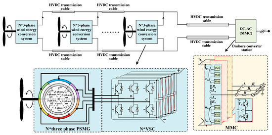
Figure 1.
The topology of the proposed wind power generation system with N* three-phase PSMG based on HVDC.
2.2. Analysis of Electromagnetic Characteristics of N* Three-Phase PMSG
The N* three-phase PMSG designed in this paper is composed of n sets of sector PMSG units sharing the same permanent magnet PM rotor and fixed on the generator base through a dovetail, as shown in Figure 2. The stator winding distribution of each sector PMSG unit is analogous to that of the traditional three-phase PMSG, and each unit has better electrical, magnetic and thermal isolation characteristics. Even if one of the PMSG units fails, it will not have a high impact on the operation of the other PMSG units. Each unit is a mutual hot backup so the whole power generation system has an excellent fault-tolerant performance.
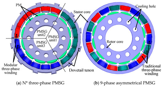
Figure 2.
Structural sketch of N* three-PMSG (N = 3) and 9-phase asymmetrical PMSG.
Figure 3 shows the winding vector and winding distribution of 3* three-phase and asymmetric 9 phase PMSG. The asymmetric 9-phase PMSG consists of n sets of three-phase symmetrical windings (n = 3) with a π/3n electrical degrees shift in space, respectively. The electrical isolation of each set of three-phase winding can be achieved by n independent neutral points, but the magnetic isolation of each set of three-phase winding cannot be achieved, as shown in Figure 3b. Furthermore, the mutual inductance between adjacent phase windings (A1, A2, A3) are large and cannot be ignored. The heavy cross-coupling between adjacent windings increases the difficulty of the control system, particularly when a winding fails. The N* three-phase generator designed in this paper consists of n sets of symmetrical three-phase windings with star-connected, which are overlapping in space, as shown in Figure 3a. The electrical, magnetic, and thermal isolation between the three-phase winding units could be realized essentially, which dramatically reduces the control difficulty of the N* three-phase PMSG.
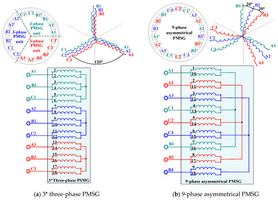
Figure 3.
Vector and winding distribution diagram.
Figure 4 shows the no-load back EMF of the 3* three-phase and asymmetric 9-phase PMSG. The phase shift between each winding can be clearly seen from the FEA results. The asymmetric 9-phase PMSG is distributed in triple three-phase sets with a 20 electrical degrees shift. However, in the 3* three-phase PMSG, both A2–B2–C2 and A3–B3–C3 represent three-phase windings in phase with A1–B1–C1. All three windings are distributed along 120 mechanical degrees along the stator circumference, which is completely consistent with the analysis in Figure 3. Compared with the asymmetric 9-phase PMSG, the coil length from phase A1 to A1’ of the 3*three-phase PMSG is the shortest and the copper loss is lower for this configuration. However, to further reduce the mutual inductance among the three-phase windings, the fractional slot concentrated winding is often used, as shown in Figure 3. The frequency spectrum analysis shows that the third harmonic is about 5.13%, the fifth harmonic is about 8.69%, and the seventh harmonic is about 6.72%, which means the content of low order harmonics is higher.
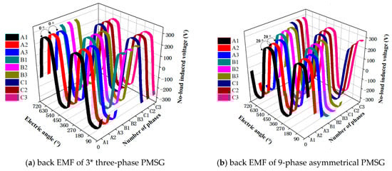
Figure 4.
No-load back EMF of 3 *three-phase and asymmetric 9-phase PMSG.
Figure 5 shows the torque curves of the 3* three-phase PMSG and asymmetric 9-phase PMSG. One or two of the generator units are in-service with the same current excitation and the rest are out-of-service. Thus, the torque for each individual unit can be obtained. It can be seen from the Figure 5a that the three-phase generator units 1, 2 or 3 of the 3* three-phase PMSG has the same electromagnetic torque. The electromagnetic torques of generator units 1 and 2 are equal to that of the generator units 1 and 3, which is twice the electromagnetic torque of generator unit 1. The electromagnetic torque of generator units 1–3 (i.e., 3* three-phase generator) is three times that of generator unit 1. It can be concluded that the torque of each generator unit is the same and the total electromagnetic torque of the N* three-phase PMSG is the sum of each generator unit, which means the electromagnetic torque of the generator unit of the N* three-phase PMSG has good independence and superposition characteristics. Figure 5b shows the torque ripple of the asymmetric 9-phase PMSG and 3* three-phase PMSG. It can be seen from the Figure 5b that the torque ripple of the asymmetric 9-phase PMSG is much smaller than that of the 3* three-phase PMSG. The 3* three-phase PMSG is essentially a three-phase generator with FSCW. The winding magnetomotive force contains ample low-order harmonics, such as 5, 7, 11 and 13, which are higher than the of asymmetric 9-phase PMSG. The higher harmonic content of the magnetomotive force increases the torque ripple and reduces the average torque at the same time.
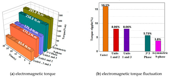
Figure 5.
Torque curves of the generators.
Figure 6 shows the flux distribution of a 3* three-phase PMSG when phase B1 is fed with rated current, while B2 and B3 are in an open circuit condition. It can be seen from the figure that there is a weak magnetic coupling between B1, B2 and B3. The mutual-inductance between B1, B2 and B3 is thereby much lower than the self-inductance of B1. The FEA result shows the self-inductance of B1 is 0.233 mH and the mutual-inductance between B1, B2 and B3 is 0.0245 mH, only 10.5% of self-inductance. Thus, the cross-coupling effect between the generator units can be ignored. During the manufacturing process of an N* three-phase PMSG, a magnetic isolation layer can be added to weaken the coupling between the generator units further. The windings of the generator units can be controlled independently and only coupled in the electromagnetic torque in the rotor. This is the basis of the control method proposed in this paper.
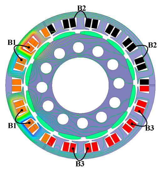
Figure 6.
Armature reaction of the winding B1.
Figure 7 shows the 3* three-phase PMSG magnetic density cloud diagram and its magnetic line distribution. It can be seen from the Diagram that the stator tooth is the part with the most significant magnetic density under a no-load condition. The magnetic line distribution in each three-phase generator unit is relatively uniform and the magnetic line coupling between the generator units is very small, which means the design method of the 3* three-phase PMSG is reasonable.
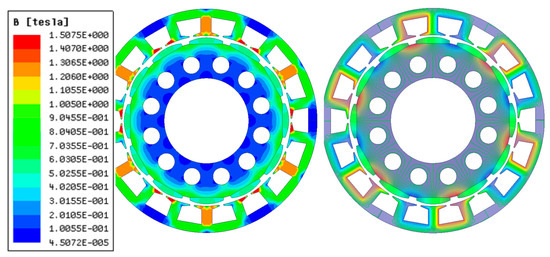
Figure 7.
Magnetic cloud and line map of 3* three-phase PMSG.
3. Mathematical Model of N* Three-Phase PMSG
Considering the analysis of the electromagnetic characteristics of the N* three-phase PMSG, it can be seen that the N* three-phase PMSG consists of n sets of three-phase PMSG units and the interaction between each unit is minimal, which could be neglected. According to reference [20], the mathematical model of the N*three-phase PMSG in the d-q coordinate system could be equivalent to that of a traditional three-phase PMSG. Thus, the d-q axes voltage transformation of one three-phase winding can be written as:
where the d-axis is oriented at an angle of θ ahead of the a-axis, and each three-phase PMSG unit shares the same rotor position angle. uai, ubi, uci and udi, uqi represent the stator voltage and d-q axis voltage of the ith three-phase PMSG unit, respectively. The state equation of the N* three-phase PMSG in a d-q coordinate system can be expressed as:
where xi and ui are the state variables and system output of the ith three-phase PMSG unit, respectively, which can be defined as follows:
and the coefficient matrix is defined as follows:
where ω is angular velocity, idi, iqi, Ldi, Lqi, Ri, ψri are stator current, inductance, resistance, and PM flux of the ith three-phase PMSG unit in the d-q coordinate system. The N* three-phase phase PMSG is composed of n sets of three-phase PMSG units with identical output characteristics. It can be seen that the PM flux, stator resistance, inductance, output voltage and torque of each unit are equal.
The total electromagnetic torque of an N* three-phase PMSG can be obtained by the sum of the torque that is generated by each three-phase PMSG unit. Te can be formulated by:
where Te is the electromagnetic torque of the N* three-phase PMSG and p is the pole-pair of the three-phase PMSG unit.
The equation of motion of the N* three-phase PMSG can be written as:
4. Harmonic Current Control Strategy of Side Converter of N* Three-Phase PMSG
An N* three-phase PMSG consists of n sets of three-phase PMSG units and the electromagnetic characteristics of each unit are identical. Therefore, one three-phase PMSG unit is controlled and the other PMSG units adopt the same control method, which means one set of the control strategy is used to realize the control of n sets of inverters. Compared with the multi-phase PMSG control strategy based on VSD, the control method proposed in this paper is simple and easy to implement. Even if a three-phase PMSG unit fails, other units could still operate normally. Figure 8 shows a schematic diagram of the connection between the N* three-phase PMSG and the side converter (n = 6).
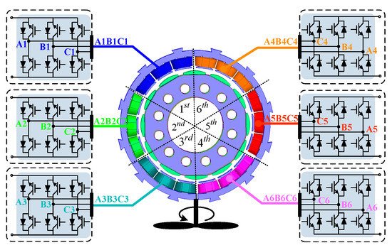
Figure 8.
Connection diagram of an N* three-phase PMSG and side converter (n = 6).
4.1. Design of Proportional Integral-Nonideal Resonance Controller
Considering the above analysis, to reduce the coupling effect among the three-phase PMSG units, the FSCW is mostly used in an N* three-phase PMSG. The current of the generator-side converter contains abundant low-order harmonics, which have a great influence on generator performance and should be suppressed. However, the vector control strategy based on rotor field orientation is generally adopted in the generator-side control of a direct drive PMSG. Its controller usually selects the traditional proportional integral (PI) regulator. The PI controller could effectively realize steady-state error-free control of the DC signal in the synchronous rotating coordinate system. However, to achieve the control of the AC signal, the AC signal needs to be converted to the DC signal and then back to the AC signal. The process of signal conversion is very complicated. Figure 9 shows the transformation block diagram of the AC–DC equivalent transfer function.
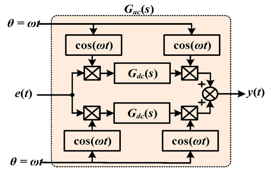
Figure 9.
Conversion block diagram of the equivalent transfer function for AC and DC signals.
The equivalent transfer function of the AC–DC signal could be expressed in the time domain as follows:
Here, we can get:
The Laplacian transformation of Equation (8) can be expressed as:
where L is the abbreviation of the Laplacian transformation, therefore:
where A and B are just two symbols, and by a Laplace transformation of Equation (7), we can get:
when the signal transformation is considered without numerical transformation, the equivalent transfer function of the AC–DC signal can be expressed by [25,26]:
The nonideal integral controller:
(Ki is the integral coefficient and ωc is the cut-off frequency) is substituted into Equation (12), Gac can be formulated by:
Equation (14) is the nonideal resonance controller (NRC). It can make the AC signal, with angular velocity ω, obtain the effect that is similar to integrating a DC signal. Simultaneously, the bandwidth of the NRC can be enlarged by setting the cut-off frequency ωc reasonably, which could reduce the sensitivity of the controller to the change of signal frequency and improve the stability of the control system. Combining NRC with the traditional PI controller, an adaptive proportional integral-nonideal resonance controller (PI-NRC) is formed to realize the steady-state error-free control of the AC and DC signals. The transfer function of PI-NRC can be expressed by:
There are multiple different harmonics to realize zero-error adjustment, then the transfer function of PI-NRC can be formulated by:
Kp and Ki are the ratio and integral coefficients of PI, h is the number of harmonics, and Khwi is the resonance gain coefficient of ith harmonic. Concerning the PI-NRC controller, the proportion coefficient has been determined in the design of the PI controller, so the harmonic signal can only be controlled by adjusting the parameters Ki and ωc of the resonance controller. Assuming the angular frequency of the controlled object ω = 314 rad/s, ωc = 10 and keeping Ki unchanged, the transfer function Bode diagram corresponding to Equation (14) is shown in Figure 10a. Through the adjusting of Ki, the amplitude-frequency curve can be shifted up or down, which not only affects the controller gain, but also affects the controller bandwidth. Therefore, in an ideal situation, the adjustment without static difference of the AC harmonic signal can be realized by a reasonable Ki, eliminating the harmonic.
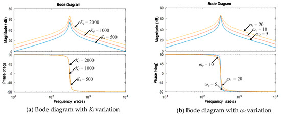
Figure 10.
Bode of the resonant controller with variable parameters.
4.2. Harmonic Suppression Strategy of N* Three-Phase PMSG Machine-Side Converter
PI-NRC is introduced into the control strategy of the N* three-phase PMSG machine-side converter to suppress low-order harmonic current in this paper. The system control block diagram is shown in Figure 11. The reference value of the q-axis current is regulated by a DC bus voltage and the reference current of the d-axis is 0, which is compared with the feedback of the d-q current. Then, the voltage reference values Udref and Uqref are obtained by adjusting the error though PI-NRC. Six identical SVPWM modulation switching signals are inputted to the converters of six generator units, respectively. Finally, the control of the whole N* three-phase PMSG is completed.
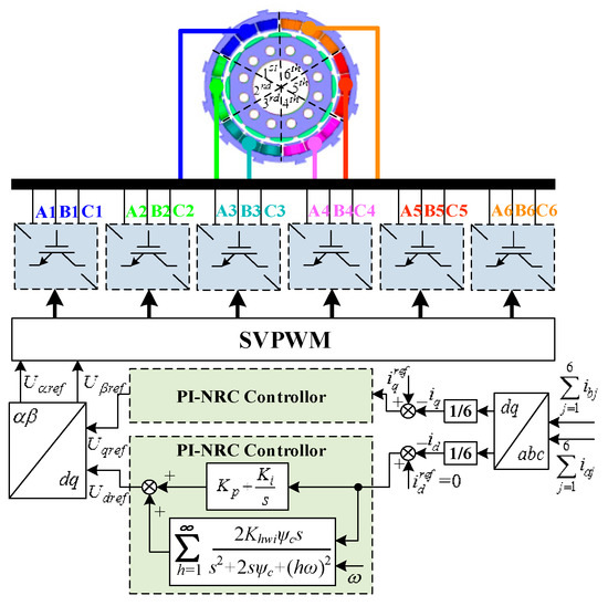
Figure 11.
Control block diagram of the N* three-phase PMSG power generation system (n = 6).
4.3. Simulation and Analysis
The generator model in MATLAB/Simulink is an ideal mathematical model without considering the harmonics in the generator system. To verify the effectiveness of the new N* three-phase PMSG and the feasibility of the proposed control strategy, the finite element simulation model of an N* three-phase PMSG established by Ansys/Maxwell is imported with the help of the Ansys/Simplorer platform. The parameters of each generator unit are identical, as shown in Table 1, and the field-circuit coupling simulation is carried out with the control strategy proposed in Simulink. The generator-side converter adopts the id = 0 control strategy and is set to a given speed mode.

Table 1.
Main parameters of a three-phase PMSG unit.
Figure 12 shows the current waveform of a 6* three-phase PMSG simulated by a traditional PI controller. Figure 12a shows the current waveform of one generator unit of a 6* three-phase PMSG. It can be seen from the figure that harmonic current always exists in a three-phase PMSG unit in half-load and full-load, and the sinusoidal degree of the stator current waveform is poor. It is found by Fourier decomposition that the odd-harmonic content in stator current is higher, among which the 5th and 7th harmonic content is the largest. Figure 12b is the current waveform of the three-phase PMSG unit in the d-q coordinate system. It can be seen from the figure that the current iq under full-load is twice as much as that under half-load. The d-q axis current response could well follow the given current, and the static error in steady-state is small. There also are apparent fluctuations in the d-q axis current.
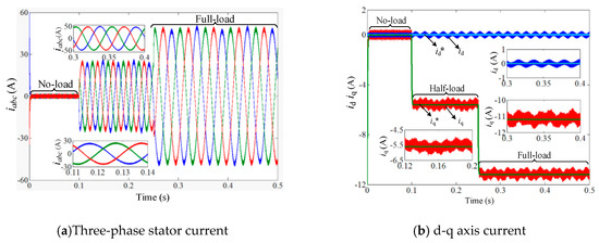
Figure 12.
Current waveforms of a three-phase PMSG unit with the PI controller.
When the traditional PI regulator is used, the amplitudes of the 5th, 7th, 11th and 13th harmonics in the stator current are larger. It is found that the 5th harmonic is a negative sequence harmonic. The negative sequence 5th harmonic and positive sequence 7th are converted to the synchronous rotating coordinate system existing as the –6th harmonic signal and 6th harmonic signal, respectively. Therefore, the NRC current controller with angular frequency of 6 ω is set. The NRC controller with an angular frequency of 10ω and 12ω is set to control the 11th and 13th harmonic currents. Figure 13 is the current waveform of a three-phase PMSG unit 1 using the PI-NRC current controller. It can be seen from the figure that the current harmonic content is less than that of the PI current controller in half-load and full-load processes. The waveform sinusoidal degree is good and the 5th, 7th, 11th and 13th current harmonics are eliminated. Figure 13b shows the current waveform in the d-q axis. It can be seen from the figure that the torque current iq under full load is twice that of the half-load. The current response in the d-q axis follows the given current well and the static error in steady-state is small. Concurrently, the current fluctuation in the q-d axis is well suppressed.
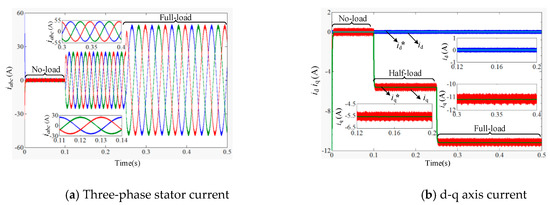
Figure 13.
Current waveforms of three-phase PMSG unit 1 with PI-NRC.
5. Experimental Results and Analysis
To further verify the feasibility of the new modular N* three-phase PMSG and the effectiveness of the current harmonic control strategy proposed in this paper, a test prototype with rated power at 120 kW was manufactured by the research group. The main parameters of the three-phase PMSG unit are shown in Table 1, and a test platform was built as shown in Figure 14.
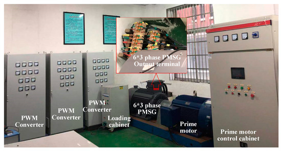
Figure 14.
6* three-phase PMSG experimental platform.
The no-load back EMF of a 6* three-phase PMSG prototype at rated speed of 500 r/min is shown in Figure 15. Figure 15a shows the no-load back EMF waveform of a three-phase PMSG unit 1. The peak voltage is about 295 V and the effective value is 208 V. The experimental test value is slightly lower than the finite element calculation value, which may be caused by the gap between the generator units in the actual production process being larger than that of the FEA model. Figure 15b shows the no-load back EMF waveform of phase_A of a three-phase PMSG units 1, 2 and 6. It can be seen from the figure that the no-load back EMF waveforms of the three generator units are relatively consistent, and the phase difference between them is 0 electric angle.
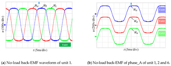
Figure 15.
No-load EMF of a 6* three-phase PMSG Prototype.
Figure 16 and Figure 17 show the current test waveforms of a three-phase PMSG unit 1 with a PI and PI-NRC controller at different speeds. According to the test results, the current harmonics can be suppressed by adopting the PI-NRC controller under different speed conditions. Compared with the traditional PI controller, the PI-NRC controller proposed in this paper has an obvious effect on harmonic suppression.
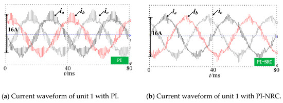
Figure 16.
Current waveform of generator unit 1 with different controllers at 300 r/min.
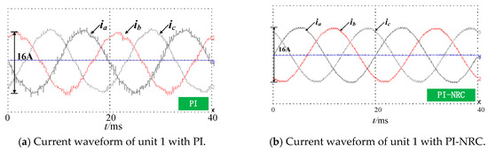
Figure 17.
Current waveform of generator unit 1 with different controllers at 500 r/min.
6. Conclusions
Due to the disadvantages of traditional large-scale three-phase direct drive permanent magnet wind turbine systems, such as complex structures and outstanding circulation problems, a new modular N* three-phase permanent magnet wind turbine with a side converter current harmonic control strategy was proposed in this paper. The conclusions of this paper are as follows:
- (1)
- The N* three-phase PMSG proposed in this paper is composed of several three-phase generator units with the same electromagnetic characteristics. Each generator unit has advantages of good electrical isolation, simple structure and strong fault tolerance.
- (2)
- The current harmonics can be suppressed by the machine-side converter control strategy of an N* three-phase PMSG proposed in this paper, which could eliminate the harmonics with higher amplitude in the stator current and improve the generating efficiency of the generator.
- (3)
- The generator proposed in this paper is suitable for the field of offshore large-capacity wind power generation, which could provide some references for engineering practice.
Author Contributions
Conceived the theory and built the model, Z.R.; performed the simulations and experiments and analyzed the data, Z.Z., G.W. and Z.L.; wrote the paper, Z.R. and Z.Z.; funding acquisition, Z.Z. and S.H. All authors have read and agreed to the published version of the manuscript.
Funding
This work was supported in part by the Natural Science Foundation of Hunan Province (2017JJ2293).
Conflicts of Interest
The authors declare no conflict of interest.
References
- De Prada, M.; Corchero, C.; Gomis-Bellmunt, O.; Sumper, A. AC-DC offshore wind power plant topology optimal design. IEEE Trans. Power Syst. 2015, 30, 1868–1876. [Google Scholar]
- Jeremy, L. Integrating the first HVDC-based offshore wind power into PJM system—A real project case study. IEEE Trans. Ind. Electron. 2015, 52, 1970–1978. [Google Scholar]
- Shoudao, H.; Wu, G.; Rong, F.; Zhang, C.; Huang, S.; Wu, Q. Novel Predictive Stator Flux Control Techniques for PMSM Drives. IEEE Trans. Power Electron. 2019, 34, 8916–8929. [Google Scholar]
- Zhang, C.; Wu, G.; Rong, F.; Feng, J.; Jia, L.; He, J.; Huang, S. Robust Fault-Tolerant Predictive Current Control for Permanent Magnet Synchronous Motors Considering Demagnetization Fault. IEEE Trans. Ind. Electron. 2018, 65, 5324–5334. [Google Scholar] [CrossRef]
- Zhou, D.; Blaabjerg, F.; Franke, T.; Tønnes, M.; Lau, M. Comparison of wind power converter reliability with low speed and medium speed permanent magnet synchronous generators. IEEE Trans. Power Syst. 2015, 62, 6575–6584. [Google Scholar]
- Potgieter, J.H.; Kamper, M.J. Modeling and stability analysis of a direct drive direct grid slip synchronous permanent magnet wind generator. IEEE Trans. Ind. Appl. 2014, 50, 1738–1747. [Google Scholar] [CrossRef]
- Zhang, X.; Chen, J.; Ma, Y.; Wang, Y.; Xu, D. Bandwidth Expansion Method for Circulating Current Control in Parallel Three-phase PWM Converter Connection System. IEEE Trans. Ind. Electron. 2014, 29, 6847–6856. [Google Scholar]
- Hou, C.C. A Multicarrier PWM for Parallel Three-Phase Active Front-End Converters. IEEE Trans. Power Electron. 2013, 28, 2753–2759. [Google Scholar] [CrossRef]
- Zhang, X.; Fu, Z.; Xiao, Y.; Wang, G.; Xu, D. Control of Parallel Three-Phase PWM Converters Under Generalized Unbalanced Operating Conditions. IEEE Trans. Power Electron. 2017, 32, 3206–3214. [Google Scholar] [CrossRef]
- Monni, A.; Marongiu, I.; Serpi, A.; Damiano, A. Design of a fractional slot multi-phase PMSG for a direct drive wind turbine. In Proceedings of the 2014 International Conference on Electrical Machines, Berlin, Germany, 2–5 September 2014; pp. 2087–2093. [Google Scholar]
- Levi, E. Advances in converter control and innovative exploitation of additional degrees of freedom for multiphase machines. IEEE Trans. Ind. Electron. 2015, 63, 433–448. [Google Scholar] [CrossRef]
- Elserougi, A.A.; Daoud, M.I.; Abdel-Khalik, A.S.; Massoud, A.M.; Ahmed, S. Series connected multi-half-bridge modules converter for integrating multi-megawatt wind multi phase permanent magnet synchronous generator with dc grid. IET Electr. Power Appl. 2017, 11, 981–990. [Google Scholar] [CrossRef]
- Zhou, S.; Rong, F.; Yin, Z.; Huang, S.; Zhou, Y. HVDC Transmission Technology of Wind Power System with Multi-Phase PMSG. Energies 2018, 11, 3294. [Google Scholar] [CrossRef]
- Gjerde, S.S.; Olsen, P.K.; Ljøkelsøy, K.; Undeland, T.M. Control and fault handling in a modular series-connected converter for a transformerless 100 kV low-weight offshore wind turbine. IEEE Trans. Ind. Appl. 2014, 50, 1094–1105. [Google Scholar] [CrossRef]
- Carmeli, M.S.; Castelli-Dezza, F.; Marchegiani, G.; Mauri, M.; Rosati, D. Design and analysis of a medium voltage DC windfarm with a transformer-less wind turbine generator. In Proceedings of the 2010 International Conference on Electrical Machines (ICEM), Rome, Italy, 6–8 September 2010; pp. 1–6. [Google Scholar]
- Prasai, A.; Yim, J.S.; Divan, D.; Bendre, A.; Sul, S.K. A new architecture for offshore wind farms. IEEE Trans. Power Electron. 2008, 23, 1198–1204. [Google Scholar] [CrossRef]
- Zabaleta, M.; Levi, E.; Jones, M. A Novel Synthetic Loading Method for Multiple Three-Phase Winding Electric Machines. IEEE Trans. Energy Convers. 2019, 34, 70–78. [Google Scholar] [CrossRef]
- Jung, E.; Yoo, H.; Sul, S.K.; Choi, H.S.; Choi, Y.Y. A Nine-Phase Permanent-Magnet Motor Drive System for an Ultrahigh-Speed Elevator. IEEE Trans. Ind. Appl. 2012, 48, 987–994. [Google Scholar] [CrossRef]
- Andriollo, M.; Bettanini, G.; Martinelli, G.; Morini, A.; Tortella, A. Analysis of Double-Star Permanent-Magnet Synchronous Generators by a General Decoupled d–q Model. IEEE Trans. Ind. Appl. 2009, 45, 1416–1424. [Google Scholar] [CrossRef]
- Liu, J.; Yang, G.J.; Li, Y.; Gao, H.W.; Su, J.Y. Eliminating the third harmonic effect for six phase permanent magnet synchronous generators in one phase open mode. IEEE Trans. Power Electron. 2014, 14, 92–104. [Google Scholar] [CrossRef][Green Version]
- Mekri, F.; Elghali, S.B.; Benbouzid, M.E.H. Fault tolerant control performance comparison of three and five phase PMSG for marine current turbine applications. IEEE Trans. Sustain. Energy 2013, 4, 425–433. [Google Scholar] [CrossRef]
- Han, X.; Jiang, D.; Zou, T.; Qu, R.; Yang, K. Two-segment three-phase PMSM drive with carrier phase-shift PWM for torque ripple and vibration reduction. IEEE Trans. Power Electron. 2019, 34, 588–599. [Google Scholar] [CrossRef]
- Luise, F.; Pieri, S.; Mezzarobba, M.; Tessarolo, A. Regenerative testing of a concentrated-winding permanent-magnet synchronous machine for offshore wind generation—Part I: Test concept and analysis. IEEE Trans. Ind. Appl. 2012, 48, 1779–1790. [Google Scholar] [CrossRef]
- Luise, F.; Pieri, S.; Mezzarobba, M.; Tessarolo, A. Regenerative testing of a concentrated-winding permanent-magnet synchronous machine for offshore wind generation—Part II: Test implementation and results. IEEE Trans. Ind. Appl 2012, 48, 1791–1796. [Google Scholar] [CrossRef]
- Yuan, X.; Allmeling, J.; Merk, W.; Stemmler, H. Stationary frame generalized integrators for current control of active power filters with zero steady state error for current harmonics of concern under unbalanced and distorted operation conditions. IEEE Trans. Ind. Appl. 2002, 38, 2134–2150. [Google Scholar]
- Zmood, D.N.; Holmes, D.G.; Bode, G. Frequency domain analysis of three phase linear current regulators. IEEE Trans. Ind. Appl. 2001, 37, 601–610. [Google Scholar] [CrossRef]


© 2020 by the authors. Licensee MDPI, Basel, Switzerland. This article is an open access article distributed under the terms and conditions of the Creative Commons Attribution (CC BY) license (http://creativecommons.org/licenses/by/4.0/).