Article

Direct Shear Experimental Study on the Mobilized Dilation Behavior of Granite in Alxa Candidate Area for High-Level Radioactive Waste Disposal

1
School of Engineering and Technology, China University of Geosciences (Beijing), Beijing 100083, China
2
Key Laboratory of Shale Gas and Geoengineering, Institute of Geology and Geophysics, Chinese Academy of Sciences, Beijing 100029, China
*
Author to whom correspondence should be addressed.
Energies 2020, 13(1), 122; https://doi.org/10.3390/en13010122
Submission received: 5 November 2019 / Revised: 20 December 2019 / Accepted: 21 December 2019 / Published: 25 December 2019
(This article belongs to the Special Issue Geomechanics for Energy and a Sustainable Environment)

Abstract

:
Dilation behavior is of great importance for reasonable modeling of the stability of the host rock of the repository for high-level radioactive waste disposal. It is a suitable method for carrying out direct shear experiments to analyze the dilation behavior of rock with well understood physical meanings. Based on a series of direct shear experiments on granite samples from the Alxa candidate area under different normal stresses, the shear stress‒shear strain and shear stress‒normal strain relations have been studied in detail. Five typical stages have been divided associated with the fracturing process and deformation behaviors of the granite samples during the experimental process, and the method to determine the typical stress thresholds has been proposed. It has also been found that the increasing normal stress may reduce the maximum dilation angle, and when the normal stress is relatively lower, the negative dilation angle may occur during the post-peak stage. According to the data collected from the direct shear tests, an empirical model of the mobilized dilation angle dependent on normal stress and plastic shear strain is proposed. This mobilized dilation angle has clear physical meanings and can be used in plastic constitutive models of the host rock of the repository, and this analysis can also be put forward to other types of geomechanical problems, including the deformation behaviors related to landslide, earthquake, and so on.

1. Introduction

Extensive studies on the geological disposal of high-level radioactive waste (HLW) have been carried out for several decades [1,2,3,4,5,6,7,8,9,10,11,12,13,14,15,16,17,18,19,20,21,22,23,24,25,26,27,28]. Alxa area is one of the three candidate areas with a large volume of granitic intrusions in China [22,23,25,29]. Geomechanical properties of the host rock are of paramount importance for evaluating the stability of the repository during the periods of construction and operation.
Owing to the effects of far field in-situ stresses or redistributed stresses induced by excavation, the shearing load may play an important role in the stability of underground opening [30,31,32,33]. Dilation behavior is considered as an important factor for better modeling of the deformation behavior of the surrounding rock mass [34,35,36]. Many previous researches have been carried out based on conventional tri-axial compression experiments on cylindrical rock samples. According to these experimental studies, different stages of stress-strain relations have been divided, and dilation behaviors have been studied associated with the process of crack propagation and acoustic emission events during the compression [1,35,37,38]. These studies are mainly on the phenomenological and mechanism researches. However, a quantified estimation of the rock dilation behavior is required. As a parameter controlling the plastic volume changes [34], the dilation angle is always used in the plastic constitutive model for rock. For example, for the flow rule:
ε ˙ i j p =   λ ˙ g σ i j
where ε ˙ i j p is the incremental plastic strain tensor, σ i j is the stress tensor, λ ˙   is a non-negative multiplier, and g is the plastic potential function. For rock and soil material, we always use the non-associated flow rule, and the plastic potential function g usually takes the form of
g =   1 2 ( σ 1 σ 3 ) + 1 2 ( σ 1 + σ 3 ) sin ψ + c
where σ 1 and σ 3 are the maximum and minimum principal stresses, c is a constant, and ψ is the dilation angle [34].
The dilation angle of rock has been widely studied in many published references [34,35,36]. In the early stage, the dilation angle was considered to be constant, and suggestions for determining the constant dilation angle for rock masses were also provided [34,39]. However, the researchers later found that the assumption of constant dilation angle should not be realistic, and different methods for describing the dilation angle have been provided considering the varying confining pressures and plastic parameters [40,41,42]. More recently, Zhao and Cai [35] proposed a mobilized dilation angle model dependent on confining pressures and plastic shear strain; thereafter, this model was put forward for analyses of rock masses [43]. Walton and Diederichs [36] argued that this model has too many parameters that are difficult for determination, and a new dilation angle was proposed with a piecewise style [36,44,45].
These studies were mainly based on conventional tri-axial compression experiments with the stress state of σ1 > σ2 = σ3 (σ1, σ2, and σ3 are the maximum, intermediate, and minimum principal stress, respectively). By a series of deductions based on the theory of plasticity, the dilation angle ψ is determined as [34]:
sin ψ =   ε ˙ v p 2 ε ˙ 1 p + ε ˙ v p
where, ε ˙ v p and ε ˙ 1 p is the volumetric and axial plastic strain increments, respectively. For the conventional tri-axial compression test, the lateral plastic strain increment ( ε ˙ 2 p = ε ˙ 3 p ) should be measured carefully to calculate ε ˙ v p = ε ˙ 1 p 2 ε ˙ 2 p . In fact, the lateral deformation is not uniform during the post-peak period, so it is not easy to measure the lateral and volumetric strain accurately.
Comparatively, the dilation angle defined according to the direct shear experiment has a very clear physical meaning, which can be better understood by the sketch presented in Figure 1a. A sketch of the direct shear experiment on a cubic sample is presented in Figure 1b. Under the effect of shear loading, a shear zone may be formed with the evolution of the fractures. In Figure 1c, an element is selected in the shear zone to illustrate the physical meaning of shear strain γ x y and dilation angle ψ . The dashed line shows the original element, and solid line shows the sheared element. The shear strain γ x y arises from the distortion of the element, and the normal strain ε y y is determined the normal deformation Δy divided by the original y-length of the element. By conducting the direct shear tests, the dilation angle ψ can be described as [34]:
tan ψ =   ε ˙ y y p / γ ˙ x y p
where, ε ˙ y y p and γ ˙ x y p are the plastic normal strain increment and plastic shear strain increment, respectively. The symbols x and y here follow the coordinate system shown in Figure 1.
Consequently, it may be a considerable choice to study the dilation behavior of rock by carrying out a series of direct shear tests under different normal stresses. In addition to the stability analyses on underground excavation, this method can also be used to study the deformation behavior related to landslide and earthquake.
Direct shear experiments have been widely used for analyzing the mechanical properties of geomaterials. For soil and sand samples, a direct shear test is usually used for studying the shear strength and deformation behaviors [46,47,48,49,50]. For rock samples, on the one hand, a direct shear test is often applied to research the strength and deformation behaviors of rock discontinuities [51,52,53,54,55,56,57,58,59,60,61]; on the other hand, a direct shear test has been carried out for studying the fracturing patterns inside the rock [31,62]. There are still very few studies discussing the deformation behavior of rock, or associating the fracturing process with the stress-strain relations under direct shear experiments [31]. The dilation behavior has been analyzed in some references by conducting direct shear tests considering various normal stresses; however, these studies are mainly focused on the descriptions based on observation, and a detailed, quantified analysis on the dilation angle is still required to be conducted.
In the Alxa candidate area, field investigations have been carried out in two sub-areas (TMS and NRG sub-areas), and four 600 m deep boreholes have been drilled in these two sub-areas. For more detailed information about the Alxa candidate area, readers are referred to [22]. Rock structures have been studied, and cored samples have been tested in the laboratory for analyzing their strength and deformation properties, seepage behaviors, and thermal effect on mechanical characteristics [22,23,25]. Nonetheless, the dilation behavior has not been studied. The mobilization of the dilation angle is still required to study for a reasonable plastic model of the underground repository.
Consequently, based on a series of direct shear experiments on the granite samples from Alxa candidate areas, the stress-strain relations will be studied in detail, and the dilation behavior will be investigated considering both the normal stress and the plastic shear strain. This paper is organized as follows: In Section 2, the granite samples, as well as the experimental setup and methods, are introduced. Thereafter, the experimental results are provided in Section 3, with a detailed characterization of both shear stress—shear strain and shear stress—normal strain relations. Section 4 provides a systematic discussion on the mobilization of dilation angle dependent on the normal stress and plastic shear strain. With collected data from the experiments, a fitted empirical model of dilation angle will be proposed.

2. Samples and Experimental Methods

2.1. Samples

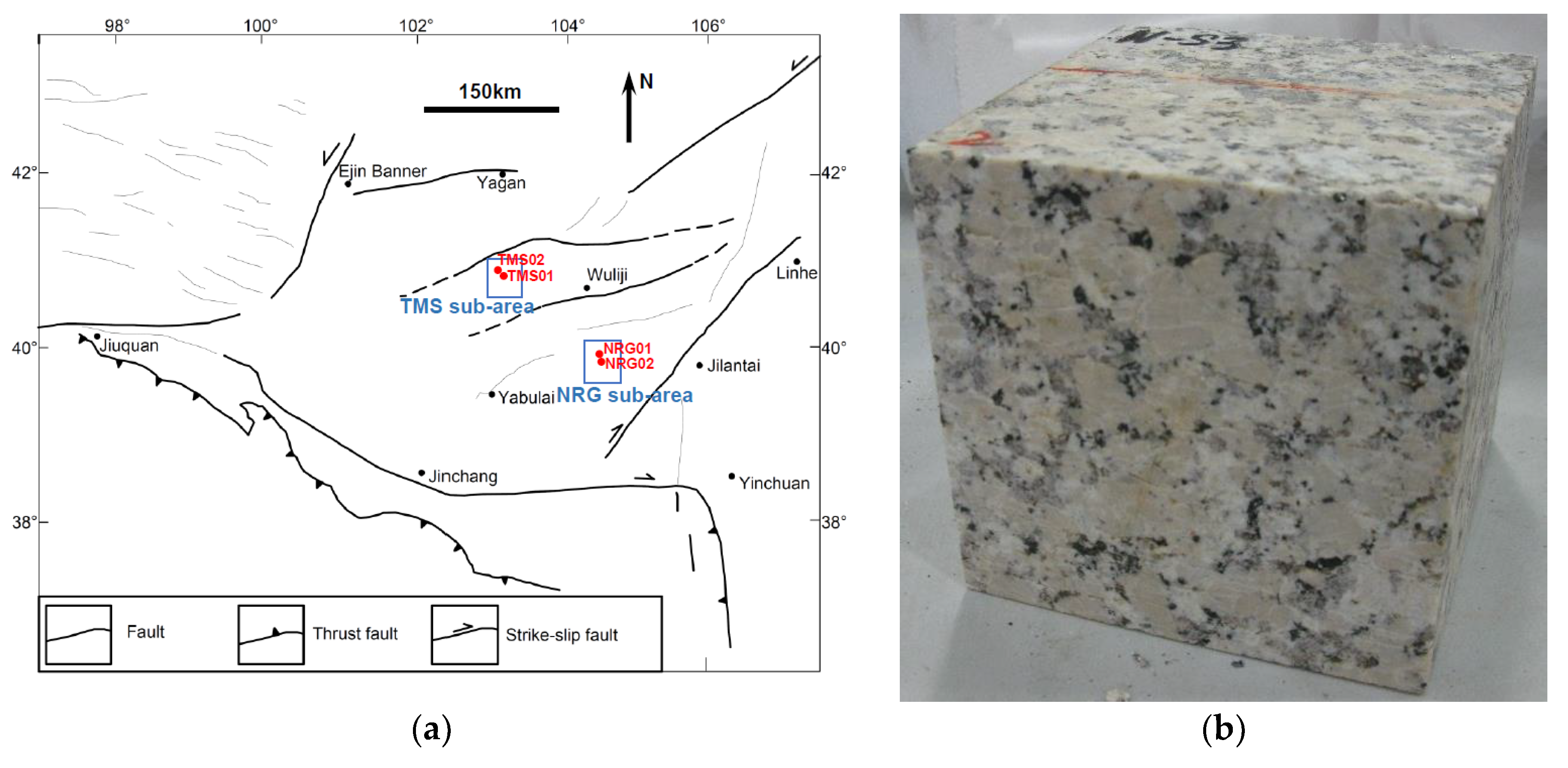
According to the previous field investigation and experimental studies on the Alxa candidate area, the granite around NRG01 borehole in NRG sub-area shows the best rock mass quality and strength behaviors in this candidate area [22]. Therefore, it is an optimal selection to use the granite samples from this site for further geomechanical studies. A schematic map of the main geological structures around the Alxa area, as well as the locations of four boreholes, are presented in Figure 2a.
As the drilled cores have a very limited diameter (about 63.5 mm), it is not easy to use the cored samples to prepare the cubic specimens suitable for the direct shear box. In this study, the granite samples are taken from a quarry near the NRG01 borehole in the Alxa candidate area. Cubic samples are well prepared with the size of 100 × 100 × 100 mm, as shown in Figure 2b. It can be seen that the samples show pink color and have heterogeneously distributed coarse grains, and they have almost the same mineral components (alkali feldspar, plagioclase, quartz, and biotite) as the cored samples. The samples have an average density of 2.61 g/mm3. Although the quarry samples are closer to the surface, it can be observed that they are only slightly weathered. These samples are still very intact, and no obvious joints or fractures are found in the specimens, so they can be used to conduct a series of analyses of the dilation behaviors in the current period when we cannot obtain the suitable specimens at depth. The detailed sizes of each of the specimens are listed in Table 1.

2.2. Experimental Methods

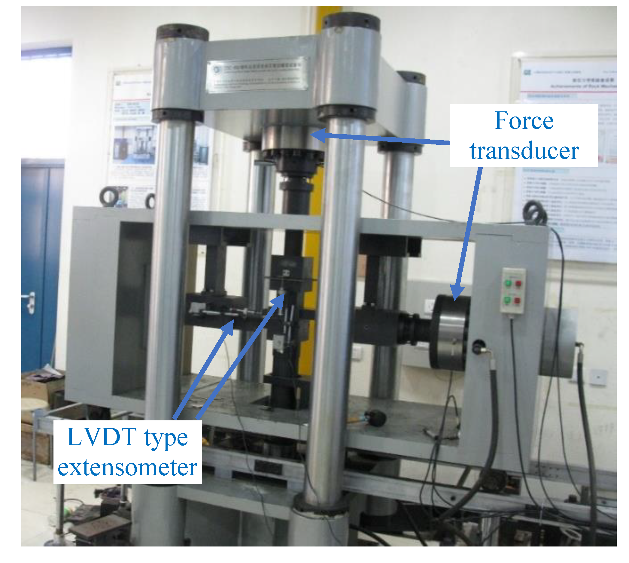
A series of direct shear experiments under different normal stresses have been carried out with a DSC-800 direct shear experimental system (Figure 3) developed by Key Laboratory of Shale Gas and Geoengineering, Chinese Academy of Sciences. The tests are conducted according to the following steps:
(1)
Each cubic granite sample is placed in the shear box. Thereafter, the normal stress is applied to the specimens to the target value. In this study, considering the loading capacity of the test machine, the normal stresses ranging from 3 to 17 MPa are applied. Actually, the results presented in the following sections show that this range of normal stresses is suitable enough to conduct a systematic analysis of the dilation behavior of these granite samples. The applied normal stress value for each specimen has been listed in Table 1.
(2)
When the normal stress reaches the designed value, shear stress is applied to each sample with a shear strain rate of 1.0 × 10⁻⁵ s−1. Each experiment continues until the shear stress reaches a residual value or the shearing failure of the specimen occurs.
(3)
During the experiment, two force transducers are installed to measure the shear and normal loads, and a pair of LVDT (linear variable differential transformer) type extensometers [36,45,63,64] are used to measure the strain values at both normal and shear directions. The data are recorded with a sampling interval of 0.02 s. With these recorded data, the shear stress‒normal strain curve and shear stress‒shear strain curve are drawn for each of the tests.
The physical process of the direct shear test on cubic samples is also illustrated in the sketch presented in Figure 1b.

3. Experimental Results

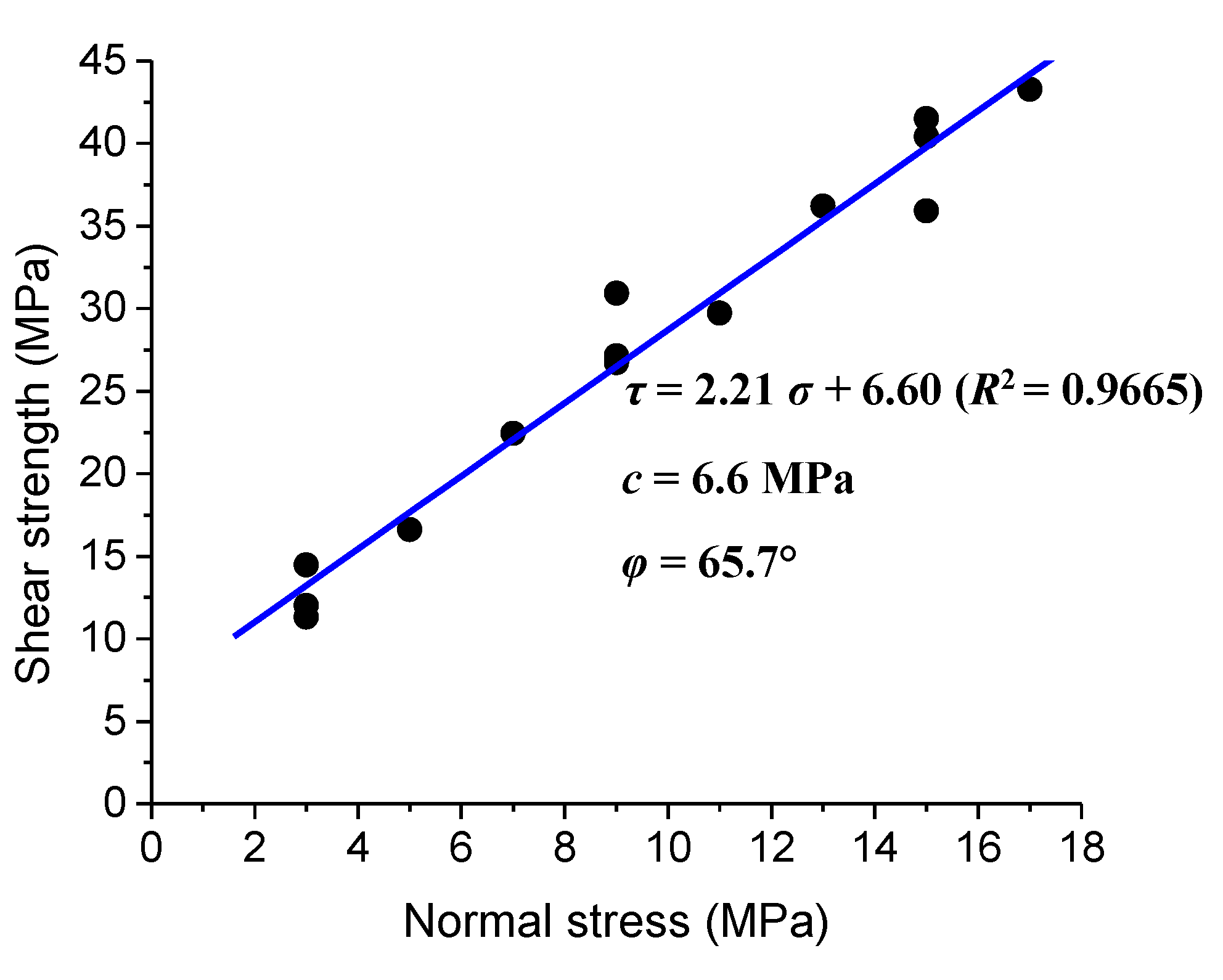
A series of peak strength values can be obtained from the direct shear tests on the granite samples under different normal stresses (Figure 4). It should be noted that only the tests under the normal stresses of 3, 9, and 15 MPa were repeated three times considering the limited numbers of the samples, and each of the tests under the other normal stresses was carried out on just one single sample. It is found that these strength values can be well fitted by the linear Coulomb criterion. The fitting result shows that the granite samples have a cohesion of 6.6 MPa and internal friction angle of 65.7°.
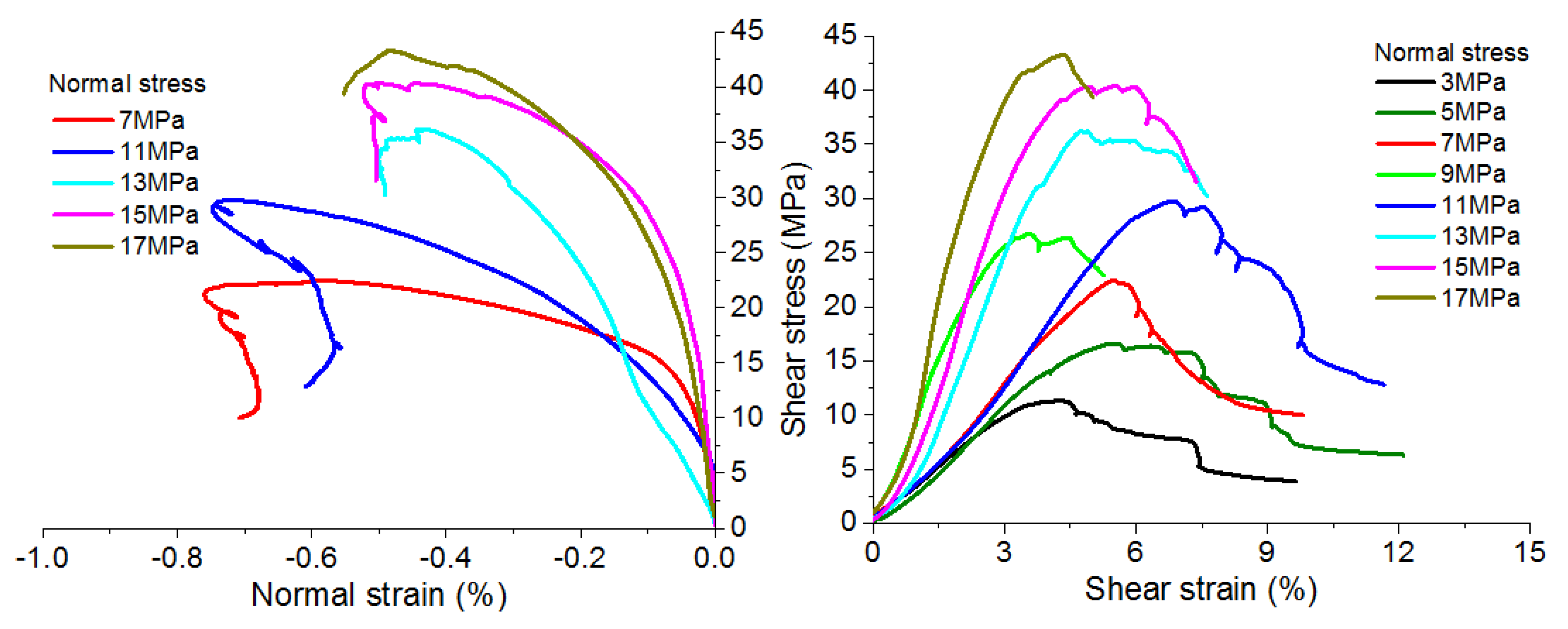
The obtained stress–strain curves are presented in Figure 5. The shear stress–shear strain curves have been obtained for each of the tests under different normal stresses. In Figure 5, only eight shear stress–shear strain curves under the eight different normal stresses (without the curves obtained from the repeated tests) are presented for clear observation. Unfortunately, the shear stress–normal strain curves have only been recorded successfully for the experiments under the normal stresses σn = 7, 11, 13, 15, and 17 MPa. Nonetheless, these curves provided enough data for the analyses in this study. It should be noted that the negative value of the normal strain means the expansion of the specimen at the direction of normal stress, and the positive value of the shear strain means the decrease of the angle ∠xoy under the effect of shear loading (according to the coordinate system, as shown in Figure 1).
According to the shear stress–shear strain curves and shear stress–normal strain curves presented in Figure 5, several characteristics can be observed as follows:
(1)
The shear stress–shear strain curves and shear stress–normal strain curves can be divided into five different stages: (I) Crack closure stage. In this stage, the slope of the shear stress–shear strain curve keeps growing to reach a constant value, showing the closure of the pre-existing cracks inside the specimen. This process may also be mixed with the effect of seating and sample adjustment. It should be noted that the normal strain curves show a slight expansion instead of crack closure induced by compaction because the crack closure process at the normal direction has occurred during the preparation process of applying a normal load, which is prior to the shear loading, so it cannot be shown in this curve. (II) Linear elastic stage. In this stage, both the shear stress–shear strain curve and the shear stress–normal strain curve behave in an almost linear style. (III) Stable crack growth stage. Although the shear stress–shear strain curve still appears linear, the normal strain shows an apparent depart from linearity. Scattered distributed cracks begin to develop in a stable way, and the onset of crack initiation also means the beginning of dilation. (IV) Unstable crack propagation stage. Both the shear strain and normal strain increase in an apparently non-linear style, meaning that crack coalescence and the unstable crack propagation occurs. (V) Post-peak stage. The shear stress decreases with the increasing shear strain, meaning that the shear zone is forming, and the shear load cannot be maintained. The detailed division of the different stages is demonstrated in Figure 6, with a typical stress-strain curve from this group of experiments. It should be noted that the information of the cracking process has not been monitored in this study, but the above-mentioned analyses are believed to be reasonable because they are based on the features of the stress-strain curves, as well as a comparison with the stage division of conventional tri-axial compression experiments [1,35,37,38].
(2)
When the normal stress is relatively low (e.g., σn = 3 and 5 MPa), the shear stress drops in a gradual manner after the failure of the specimen, showing relatively ductile post-peak behavior; with increasing normal stress, the post-peak behavior turns to be more brittle. Under the normal stress σn = 13 MPa to 17 MPa, it seems that the granite samples are prone to fail before reaching the residual shear strength. It appears that the direct shear test results show a ductile–brittle transition behavior, instead of the brittle–ductile transition behavior usually found in the conventional tri-axial compression experiments [35]. This study tries to provide an explanation as follows: For the cases under lower normal stresses, the peak shear strength is lower, so the strain energy stored in the test system is also lower. Consequently, lower strain energy will be released when failure occurs; therefore, the shear stress drops in a more stable manner. On the other hand, the higher normal stress may result in higher peak shear strength, and higher strain energy will be released during the post-peak stage, leading to a more violent failure of the specimen. It should be noted that the post-peak behavior should also be closely related to the fracturing patterns under different normal stresses, which requires a more systematic research.
(3)
When the failure occurs, the normal strain is apparently higher under relatively lower normal stresses (e.g., σn = 7 MPa and 11 MPa) than that under higher stresses (e.g., σn = 13, 15, and 17 MPa). It is interesting to find that the normal strain may decrease during the post-failure stage. This decrease is more obvious for the samples under lower normal stresses (e.g., σn = 7 and 11 MPa). This phenomenon is related to the dilation behavior and will be discussed in detail in the next section.

4. Data Analyses and Discussion

4.1. Methods

Based on the results obtained from the direct shear experiments on the granite samples under different normal stresses, the dilation angle can be calculated according to Equation (4) presented in Section 1. It should be noted that there is a negative sign in this equation, as the normal strain ε y y is defined as negative when the specimen has an expansion at the direction of normal stress in this study.
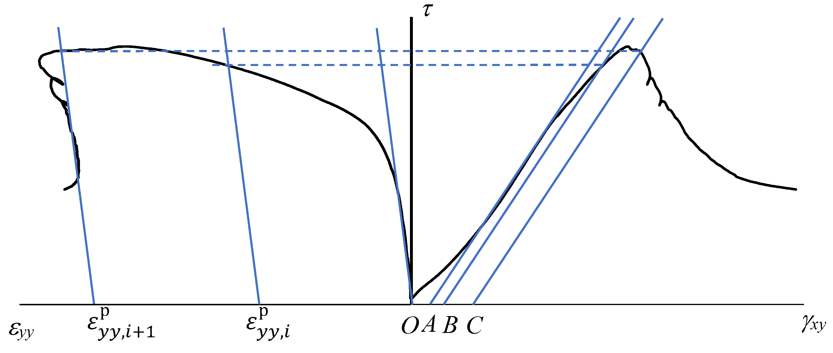
Based on the definition in Equation (4), a series of plastic normal strain and plastic shear strain values should be obtained in order to analyze the dilation behavior of the granite samples under the direct shear experiments. The cyclic loading and unloading test is an ideal method to differentiate the elastic and plastic components of the normal and shear strains at each cycle. However, it is not easy to control this type of test, especially during the post-peak stage, when the fractures always propagate in an unstable manner. Furthermore, the data will be limited by the number of cycles. Therefore, another method is used, assuming that the unloading modulus is the same as the initial deformation modulus, and this method has been widely accepted in many studies [35,36,44]. In this way, a series of assumed loading-unloading cycles can be obtained by carrying out the common direct shear experiments. Thereafter, a series of plastic normal strain and shear strain values can be collected. A sketch of this method is provided in Figure 7. A series of lines parallel with the tangent lines at the linear elastic stage of the τεyy curves and τγxy curves are drawn to determine the plastic normal strain ε y y , i p and plastic shear strain γ x y , i p , respectively. The symbol i here means a series of positive integers, showing that a series of plastic strain values can be collected with this method. It should be noted that there is a gap | O A | owing to the crack closure stage of σ1ε1 curves, so this gap should be removed when determining the plastic shear strain γ x y , i p :
γ x y , i p =   | O B | | O A | ,     γ x y , i + 1 p =   | O C | | O A | .
According to the plastic normal and shear strain values, the dilation angle can be calculated by the following Equation:
tan ψ =   ε ˙ y y p / γ ˙ x y p = ε y y , i + 1 p ε y y , i p γ x y , i + 1 p γ x y , i p .
With this method, the dilation angles of the granite samples under different normal stresses can be obtained, and the dilation behaviors of the specimens will be discussed.

4.2. Mobilized Dilation Angle of the Granite Samples Dependent on Normal Stress and Plastic Shear Strain

With the obtained plastic normal and shear strain values under various normal stresses, their relations are illustrated as the curves in Figure 8. It can be found that the plastic normal strain values are negative for all the cases, showing a plastic expanding deformation during the tests. The plastic normal strain expands significantly at the beginning stage with increasing plastic shear strain; thereafter, it turns flat and reaches a peak value. For the cases under lower normal stress (e.g., σn = 7 and 11 MPa), the expanding of plastic normal strain has a slight decrease after the peak value, while this phenomenon has not been observed for the cases with higher normal stresses (e.g., σn = 13, 15, and 17 MPa).
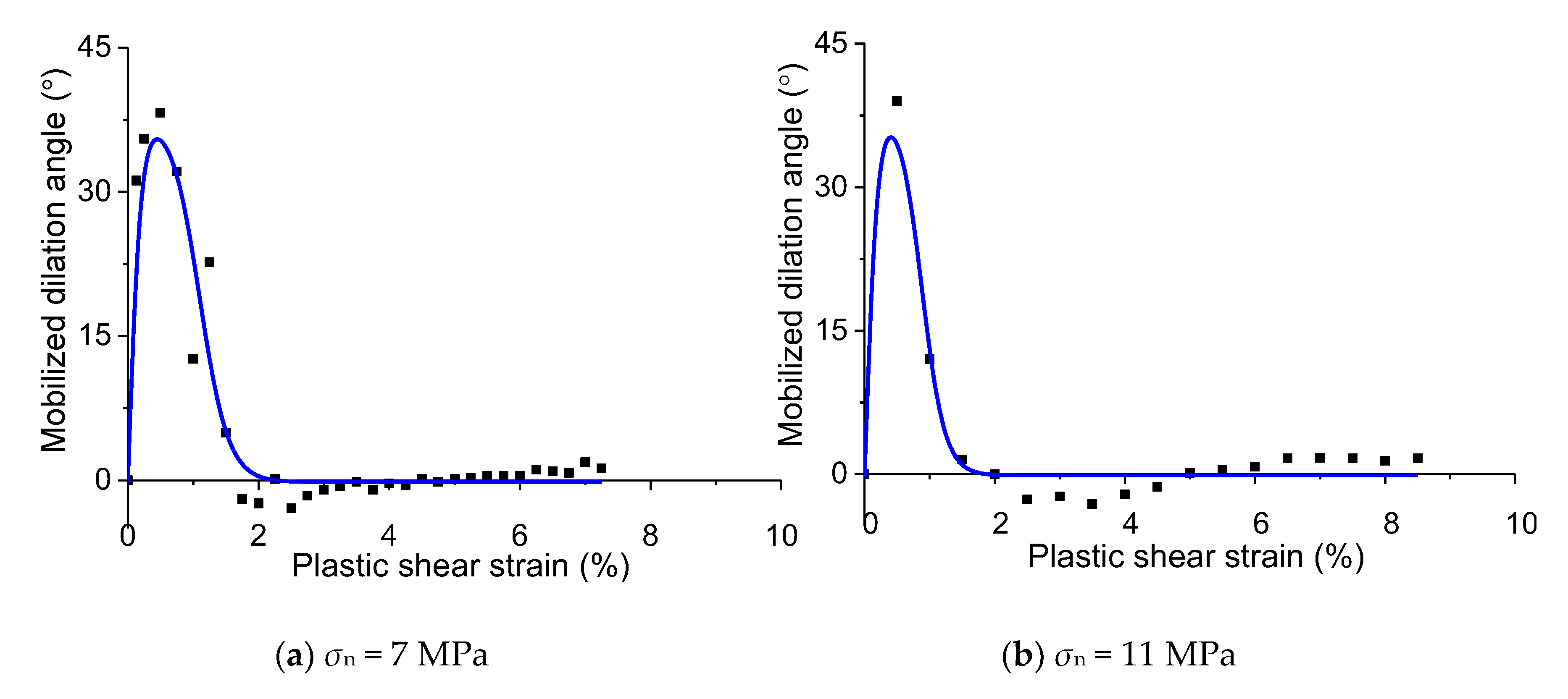
The calculated dilation angle values are presented in Figure 9. It can be found that the dilation angle is mobilized depending on the normal stress and plastic shear strain. According to the mobilization of the dilation angles, several features can be observed as follows:
(1)
For all the tests under different normal stresses, the dilation angle increases significantly to the peak value firstly with the increasing plastic shear strain; thereafter, it drops to a residual value.
(2)
For the cases under higher normal stresses (e.g., σn = 13, 15, and 17 MPa), the dilation angles are all positive. The peak value of the dilation angle is lower than that under the lower normal stresses; however, the residual value is relatively higher.
(3)
When the normal stress is relatively lower (e.g., σn = 7 and 11 MPa), the maximum dilation angle is higher, and it drops in a more significant manner. The dilation angle can even drop to a negative value, meaning the behavior of “contraction” occurs. However, the absolute value of the negative dilation angle is not very high.
The mobilized dilation angle can be well fitted by the following equation:
ψ =   ψ max [ 2 1 + exp ( 5 γ p γ φ , max p ) 1 ] ( ψ max ψ r ) [ 1 1 + exp ( 5 2 γ p γ φ , r p γ φ , r p ) ]
where, ψ max and ψ r are the maximum and residual values of the dilation angle, respectively; γ φ , max p is the plastic shear strain when the dilation angle reaches the peak value; γ φ , r p is the plastic shear strain when the dilation angle approaches the residual value.
The fitted parameters are presented in Table 2.
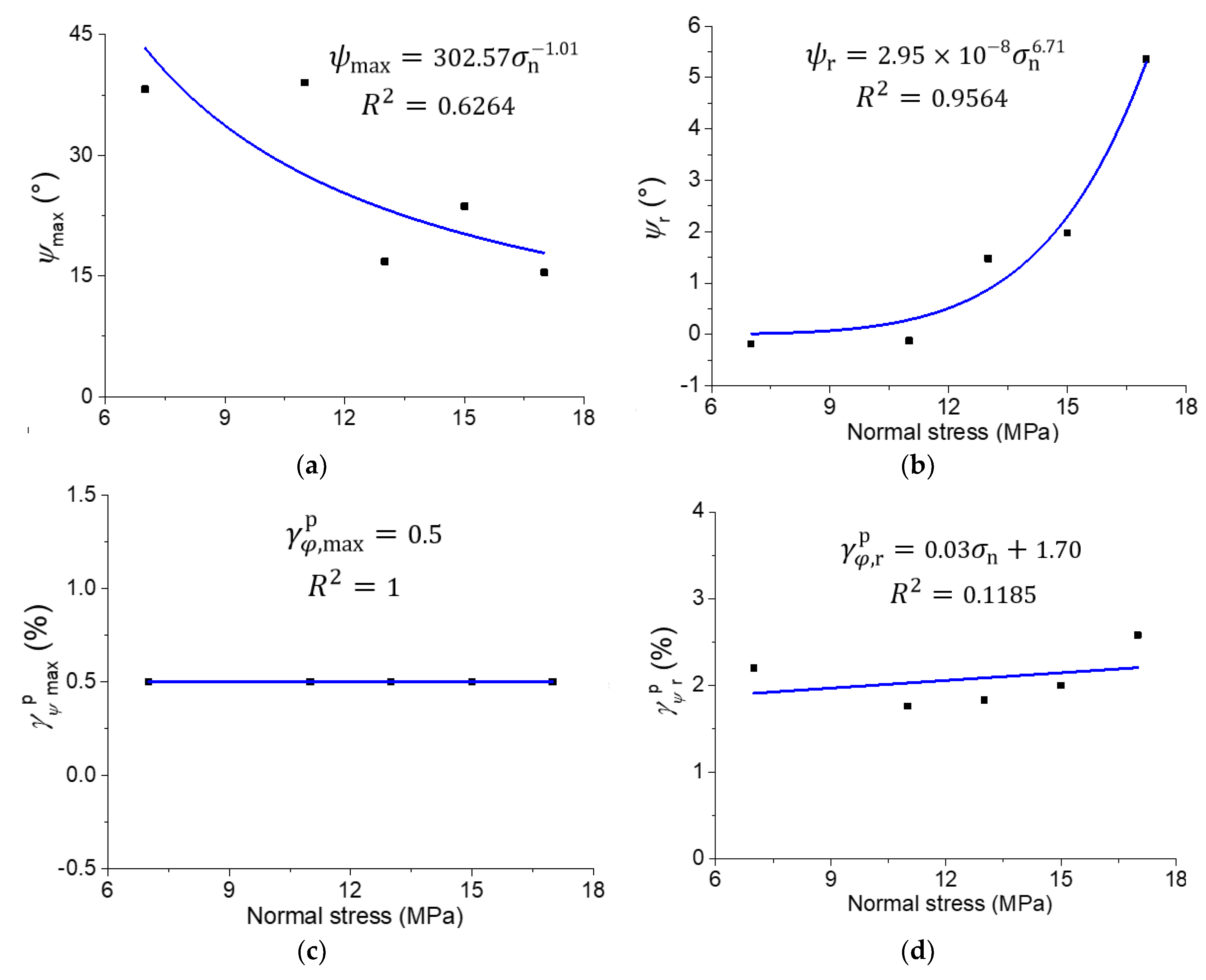
According to Table 2, the four parameters are dependent on the normal stress values. With the fitted data in Table 2, the four parameters can be further fitted with Equations (8)–(11). The fitted curves and equations are presented in Figure 10.
ψ max = a 1 σ n b 1
ψ r = a 2 σ n b 2
γ φ , max p = a 3
γ φ , r p = a 4 σ n + b 4
This empirical mobilized dilation angle has clear physical meanings, and the parameters can be easily determined by conducting a series of direct shear tests. This model can be used in the plastic constitutive models (as shown in Equations (1) and (2) for an example) for describing the deformation behavior of the host rock of the repository for HLW disposal. It may also be extended to other types of rock engineering. In future studies, we should conduct more experiments on different types of rock to extend the applicability of this model.

5. Conclusions

Based on a series of direct shear experiments on the granite samples from the Alxa candidate area in China for HLW disposal, this paper supplied a systematic analysis of the shear stress–shear strain and shear stress–normal strain relations. The dilation behaviors of the granite samples were especially studied in detail, and an empirical model on the mobilization of dilation angle dependent on the normal stress and plastic shear strain was proposed. The main contributions are as follows:
(1)
The shear stress–shear strain curves and shear stress–normal strain curves are divided into five typical stages, which are associated with the deformation and fracturing process. The typical stress thresholds were proposed to divide the different stages.
(2)
It is found that the increasing normal stress may reduce the maximum dilation angle. When the normal stress is lower, the negative dilation angle may occur; however, this phenomenon has not been observed in the cases under higher normal stresses.
(3)
An empirical model of the mobilized dilation angle dependent on normal stress and plastic shear strain is proposed based on the fitting of the data collected from the direct shear tests. This model can be used in further studies on the constitutive modeling of the host rock.
This study provided a method to analyze the mobilization angle of rock under direct shear test. The proposed model has well understood physical meanings, and it is easy to determine the values of the parameters. This study can be used for better modeling on the stability of the repository for HLW disposal, and this method can also be put forward to analyze the stability of other geomechanical problems, including the deformation behaviors related to landslides, earthquakes, and so on.
It should also be noted that the effect of temperature induced by the nuclear waste cannot be ignored when considering the mechanical behavior of the host rock, so more studies are required considering the effect of heat on the dilation behavior of the granite samples. In addition, more systematic experimental studies on more types of rock associated with the monitoring of the fracturing process will be conducted to extend the applicability of the dilation angle model supplied in this study.

Author Contributions

Conceptualization, C.C. and X.L.; methodology, C.C., X.L. and N.X.; formal analysis, C.C. and N.X.; investigation, C.C. and B.Z.; data curation, C.C. and B.Z.; funding acquisition, X.L. and N.X.; writing—original draft preparation, C.C.; writing—review and editing, C.C. All authors have read and agreed to the published version of the manuscript.

Funding

This research was funded by the Fundamental Research Funds for the Central Universities (Grant No. 2-9-2018-087); the National Natural Science Foundation of China (Grant No. 41772326); the “Double First Class” Fund of Beijing and the High-Level Radioactive Waste Disposal Project of the State Administration for Science, Technology and Industry for National Defense, China. The APC was funded by the “Double First Class” Fund of Beijing.

Acknowledgments

S. Li from the Institute of Geology and Geophysics, Chinese Academy of Sciences is appreciated here for his support for this work. Y. Dong and Y. Xie are also appreciated for his help in this study. Karim Diallo is acknowledged for checking the language of this manuscript. The anonymous peer-reviewers are all appreciated for giving very helpful comments and suggestions to improve this paper.

Conflicts of Interest

The authors declare no conflict of interest.

References

  1. Martin, C.D. The Strength of Massive Lac du Bonnet Grantie around Underground Openings; University of Manitoba: Winnipeg, MB, Canada, 1993. [Google Scholar]
  2. Makurat, A.; Ahola, M.; Khair, K.; Noorishad, J.; Rosengren, L.; Rutqvist, J. The decovalex test—Case one. Int. J. Rock Mech. Min. Sci. Geomech. Abstr. 1995, 32, 399–408. [Google Scholar] [CrossRef]
  3. Martin, C.D.; Read, R.S.; Martino, J.B. Observations of brittle failure around a circular test tunnel. Int. J. Rock Mech. Min. Sci. 1997, 34, 1065–1073. [Google Scholar] [CrossRef]
  4. Duevel, B.; Haimson, B. Mechanical characterization of pink lac du bonnet granite: Evidence of nonlinearity and anisotropy. Int. J. Rock Mech. Min. Sci. 1997, 34, 18. [Google Scholar] [CrossRef]
  5. Martin, C.D. Seventeenth canadian geotechnical colloquium: The effect of cohesion loss and stress path on brittle rock strength. Can. Geotech. J. 1997, 34, 698–725. [Google Scholar] [CrossRef]
  6. Hökmark, H.; Fälth, B. Thermal Dimensioning of the Deep Repository; TR-03-09; SKB, 2003; Available online: http://www.skb.se/publication/21133/TR-03-09.pdf (accessed on 13 July 2016).
  7. Fairhurst, C. Nuclear waste disposal and rock mechanics: Contributions of the underground research laboratory (url), pinawa, manitoba, canada. Int. J. Rock Mech. Min. Sci. 2004, 41, 1221–1227. [Google Scholar] [CrossRef]
  8. Martino, J.B.; Chandler, N.A. Excavation-induced damage studies at the underground research laboratory. Int. J. Rock Mech. Min. Sci. 2004, 41, 1413–1426. [Google Scholar] [CrossRef]
  9. Read, R.S. 20 years of excavation response studies at aecl’s underground research laboratory. Int. J. Rock Mech. Min. Sci. 2004, 41, 1251–1275. [Google Scholar] [CrossRef]
  10. Wanne, T.; Johansson, E.; Potyondy, D.; Saanio; Oy, R. Spö Pillar Stability Experiment: Final Coupled 3d Thermo-Mechanical Modeling: Preliminary Particle-Mechanical Modeling; R-04-03; Svensk Kärnbränslehantering AB, 2004; p. 40. Available online: http://www.skb.se/upload/publications/pdf/R-04-03.pdf (accessed on 23 December 2019).
  11. Wang, J. High-level radioactive waste disposal in China: Update 2010. J. Rock Mech. Geotech. Eng. 2010, 2, 1–11. [Google Scholar]
  12. Galamboš, M.; Rosskopfová, O.G.; Kufčáková, J.; Rajec, P. Utilization of slovak bentonites in deposition of high-level radioactive waste and spent nuclear fuel. J. Radioanal. Nucl. Chem. 2011, 288, 765–777. [Google Scholar] [CrossRef]
  13. Zhao, X.G.; Wang, J.; Cai, M.; Cheng, C.; Ma, L.K.; Su, R.; Zhao, F.; Li, D.J. Influence of unloading rate on the strainburst characteristics of Beishan granite under true-triaxial unloading conditions. Rock Mech. Rock Eng. 2013, 1–17. [Google Scholar] [CrossRef]
  14. Zhao, X.G.; Wang, J.; Cai, M.; Ma, L.K.; Zong, Z.H.; Wang, X.Y.; Su, R.; Chen, W.M.; Zhao, H.G.; Chen, Q.C.; et al. In-situ stress measurements and regional stress field assessment of the Beishan area, China. Eng. Geol. 2013, 163, 26–40. [Google Scholar] [CrossRef]
  15. Adamcová, R.; Suraba, V.; Krajňák, A.; Rosskopfová, O.; Galamboš, M. First shrinkage parameters of slovak bentonites considered for engineered barriers in the deep geological repository of high-level radioactive waste and spent nuclear fuel. J. Radioanal. Nucl. Chem. 2014, 302, 737–743. [Google Scholar] [CrossRef]
  16. Wang, J. On area-specific underground research laboratory for geological disposal of high-level radioactive waste in china. J. Rock Mech. Geotech. Eng. 2014, 6, 99–104. [Google Scholar] [CrossRef] [Green Version]
  17. Bond, A.E.; Chittenden, N.; Fedors, R.; Lang, P.; McDermott, C.; Neretnieks, I.; Pan, P.; Šembera, J.; Watanabe, N.; Yasuhara, H. Coupled THMC Modelling of a Single Fracture in Novaculite for Decovalex-2015. In Proceedings of the 1st International Conference on Discrete Fracture Network Engineering, Vancouver, BC, Canada, 19–22 October 2014. [Google Scholar]
  18. Chen, L.; Wang, J.; Zong, Z.; Liu, J.; Su, R.; Guo, Y.; Jin, Y.; Chen, W.; Ji, R.; Zhao, H. A new rock mass classification system QHLW for high-level radioactive waste disposal. Eng. Geol. 2015, 190, 33–51. [Google Scholar] [CrossRef]
  19. Hoorelbeke, J.-M.; Lagrange, M.-H.; Chabert, C. Impact of Minor Actinide Transmutation Options on Geological Disposal: The French Case; Fast Reactors and Related Fuel Cycles: Safe Technologies and Sustainable Scenarios (FR13). In Proceedings of the International Conference on Fast Reactors And Related Fuel Cycles, Paris, France, 4–7 March 2013. [Google Scholar]
  20. Zhao, X.G.; Cai, M.; Wang, J.; Li, P.F. Strength comparison between cylindrical and prism specimens of Beishan granite under uniaxial compression. Int. J. Rock Mech. Min. Sci. 2015, 76, 10–17. [Google Scholar] [CrossRef]
  21. Zhao, X.G.; Wang, J.; Qin, X.H.; Cai, M.; Su, R.; He, J.G.; Zong, Z.H.; Ma, L.K.; Ji, R.L.; Zhang, M.; et al. In-situ stress measurements and regional stress field assessment in the Xinjiang candidate area for China’s HLW disposal. Eng. Geol. 2015, 197, 42–56. [Google Scholar] [CrossRef]
  22. Cheng, C.; Li, X.; Li, S.; Zheng, B. Geomechanical studies on granite intrusions in Alxa area for high-level radioactive waste disposal. Sustainability 2016, 8, 1329. [Google Scholar] [CrossRef] [Green Version]
  23. Song, F.; Dong, Y.-H.; Xu, Z.-F.; Zhou, P.-P.; Wang, L.-H.; Tong, S.-Q.; Duan, R.-Q. Granite microcracks: Structure and connectivity at different depths. J. Asian Earth Sci. 2016, 124, 156–168. [Google Scholar] [CrossRef]
  24. Zhao, X.G.; Wang, J.; Chen, F.; Li, P.F.; Ma, L.K.; Xie, J.L.; Liu, Y.M. Experimental investigations on the thermal conductivity characteristics of Beishan granitic rocks for China’s HLW disposal. Tectonophysics 2016, 683, 124–137. [Google Scholar] [CrossRef]
  25. Cheng, C.; Li, X.; Li, S.; Zheng, B. Failure behavior of granite affected by confinement and water pressure and its influence on the seepage behavior by laboratory experiments. Materials 2017, 10, 798. [Google Scholar] [CrossRef] [Green Version]
  26. Marschall, P.; Giger, S.; De La Vassière, R.; Shao, H.; Leung, H.; Nussbaum, C.; Trick, T.; Lanyon, B.; Senger, R.; Lisjak, A.; et al. Hydro-mechanical evolution of the edz as transport path for radionuclides and gas: Insights from the mont terri rock laboratory (switzerland). Swiss J. Geosci. 2017, 110, 173–194. [Google Scholar] [CrossRef]
  27. Wang, J.; Chen, L.; Su, R.; Zhao, X. The Beishan underground research laboratory for geological disposal of high-level radioactive waste in China: Planning, site selection, site characterization and in situ tests. J. Rock Mech. Geotech. Eng. 2018, 10, 411–435. [Google Scholar] [CrossRef]
  28. Zhao, X.G.; Zhao, Z.; Guo, Z.; Cai, M.; Li, X.; Li, P.F.; Chen, L.; Wang, J. Influence of thermal treatment on the thermal conductivity of Beishan granite. Rock Mech. Rock Eng. 2018, 51, 2055–2074. [Google Scholar] [CrossRef]
  29. Zhou, J.; Lan, H.; Zhang, L.; Yang, D.; Song, J.; Wang, S. Novel grain-based model for simulation of brittle failure of Alxa porphyritic granite. Eng. Geol. 2019, 251, 100–114. [Google Scholar] [CrossRef]
  30. Ahlgren, S.G. The nucleation and evolution of riedel shear zones as deformation bands in porous sandstone. J. Struct. Geol. 2001, 23, 1203–1214. [Google Scholar] [CrossRef] [Green Version]
  31. Cho, N.; Martin, C.D.; Sego, D.C. Development of a shear zone in brittle rock subjected to direct shear. Int. J. Min. 2008, 45, 1335–1346. [Google Scholar]
  32. Précigout, J.; Stünitz, H. Evidence of phase nucleation during olivine diffusion creep: A new perspective for mantle strain localisation. Earth Planet. Sci. Lett. 2016, 455, 94–105. [Google Scholar] [CrossRef] [Green Version]
  33. Précigout, J.; Stünitz, H.; Villeneuve, J. Excess water storage induced by viscous strain localization during high-pressure shear experiment. Sci. Rep. 2019, 9, 3463. [Google Scholar]
  34. Vermeer, P.A.; De Borst, R. Non-associated plasticity for soils, concrete and rock. HERON 1984, 29, 1–64. [Google Scholar]
  35. Zhao, X.G.; Cai, M. A mobilized dilation angle model for rocks. Int. J. Rock Mech. Min. Sci. 2010, 47, 368–384. [Google Scholar] [CrossRef]
  36. Walton, G.; Diederichs, M.S. A new model for the dilation of brittle rocks based on laboratory compression test data with separate treatment of dilatancy mobilization and decay. Geotech. Geol. Eng. 2015, 33, 661–679. [Google Scholar] [CrossRef]
  37. Diederichs, M.S.; Kaiser, P.K.; Eberhardt, E. Damage initiation and propagation in hard rock during tunnelling and the influence of near-face stress rotation. Int. J. Rock Mech. Min. Sci. 2004, 41, 785–812. [Google Scholar] [CrossRef]
  38. Cai, M. Practical estimates of tensile strength and Hoek-Brown strength parameter mi of brittle rocks. Rock Mech Rock Eng 2010, 43, 167–184. [Google Scholar] [CrossRef]
  39. Hoek, E.; Brown, E.T. Practical estimates of rock mass strength. Int. J. Rock Mech. Min. Sci. 1997, 34, 1165–1186. [Google Scholar] [CrossRef]
  40. Detournay, E. Elastoplastic model of a deep tunnel for a rock with variable dilatancy. Rock Mech. Rock Eng. 1986, 19, 99–108. [Google Scholar] [CrossRef]
  41. Alejano, L.R.; Alonso, E. Considerations of the dilatancy angle in rocks and rock masses. Int. J. Rock Mech. Min. Sci. 2005, 42, 481–507. [Google Scholar] [CrossRef]
  42. Yuan, S.-C.; Harrison, J. An empirical dilatancy index for the dilatant deformation of rock. Int. J. Rock Mech. Min. Sci. 2004, 4, 679–686. [Google Scholar] [CrossRef]
  43. Zhao, X.G.; Cai, M. Influence of plastic shear strain and confinement-dependent rock dilation on rock failure and displacement near an excavation boundary. Int. J. Rock Mech. Min. Sci. 2010, 47, 723–738. [Google Scholar] [CrossRef]
  44. Walton, G.; Arzúa, J.; Alejano, L.R.; Diederichs, M.S. A laboratory-testing-based study on the strength, deformability, and dilatancy of carbonate rocks at low confinement. Rock Mech. Rock Eng. 2015, 48, 941–958. [Google Scholar] [CrossRef]
  45. Walton, G.; Alejano, L.R.; Arzua, J.; Markley, T. Crack damage parameters and dilatancy of artificially jointed granite samples under triaxial compression. Rock Mech. Rock Eng. 2018, 51, 1637–1656. [Google Scholar] [CrossRef]
  46. Cresswell, A.W.; Barton, M.E. Direct shear tests on an uncemented, and a very slightly cemented, locked sand. Q. J. Eng. Geol. Hydrogeol. 2003, 36, 119–132. [Google Scholar] [CrossRef]
  47. Simoni, A.; Houlsby, G.T. The direct shear strength and dilatancy of sand–gravel mixtures. Geotech. Geol. Eng. 2006, 24, 523. [Google Scholar] [CrossRef]
  48. Hamidi, A.; Azini, E.; Masoudi, B. Impact of gradation on the shear strength-dilation behavior of well graded sand-gravel mixtures. Sci. Iran. 2012, 19, 393–402. [Google Scholar] [CrossRef] [Green Version]
  49. Chu, L.-M.; Yin, J.-H. Comparison of interface shear strength of soil nails measured by both direct shear box tests and pullout tests. J. Geotech. Geoenviron. Eng. 2005, 131, 1097–1107. [Google Scholar] [CrossRef]
  50. Bagherzadeh-Khalkhali, A.; Mirghasemi, A.A. Numerical and experimental direct shear tests for coarse-grained soils. Particuology 2009, 7, 83–91. [Google Scholar] [CrossRef]
  51. Lajtai, E.Z. Shear strength of weakness planes in rock. Int. J. Rock Mech. Min. Sci. Geomech. Abstr. 1969, 6, 499–515. [Google Scholar] [CrossRef]
  52. Barton, N. A model study of rock-joint deformation. Int. J. Rock Mech. Min. Sci. Geomech. Abstr. 1972, 9, 579–582. [Google Scholar] [CrossRef]
  53. Bandis, S. Experimental Studies of Scale Effects on Shear Strength, and Deformation of Rock Joints. Ph.D. Thesis, University of Leeds, Leeds, UK, 1980. [Google Scholar]
  54. Barton, N.; Bandis, S. Some effects of scale on the shear strength of joints. Int. J. Rock Mech. Min. Sci. Geomech. Abstr. 1980, 17, 69–73. [Google Scholar] [CrossRef]
  55. Gehle, C.; Kutter, H.K. Breakage and shear behaviour of intermittent rock joints. Int. J. Rock Mech. Min. Sci. 2003, 40, 687–700. [Google Scholar] [CrossRef]
  56. Li, H.; Feng, H.; Liu, B. Study on strength behaviors of rock joints under different shearing deformation velocities. Chin. J. Rock Mech. Eng. 2006, 12, 11. [Google Scholar]
  57. Ghazvinian, A.; Nikudel, M.; Sarfarazi, V. Effect of Rock Bridge Continuity and Area on Shear Behavior of Joints. In Proceedings of the 11th Congress of the International Society for Rock Mechanics, Lisbon, Portugal, 9–13 July 2007. [Google Scholar]
  58. Tang, Z.; Xia, C.; Xiao, S. Constitutive model for joint shear stress-displacement and analysis of dilation. Chin. J. Rock Mech. Eng. 2011, 30, 917–925. [Google Scholar]
  59. Ghazvinian, A.; Sarfarazi, V.; Schubert, W.; Blumel, M. A study of the failure mechanism of planar non-persistent open joints using pfc2d. Rock Mech. Rock Eng. 2012, 45, 677–693. [Google Scholar] [CrossRef]
  60. Tian, H.; Chen, W.; Yang, D.; Yang, J. Experimental and numerical analysis of the shear behaviour of cemented concrete–rock joints. Rock Mech. Rock Eng. 2015, 48, 213–222. [Google Scholar] [CrossRef]
  61. Zheng, B.; Qi, S. A new index to describe joint roughness coefficient (JRC) under cyclic shear. Eng. Geol. 2016, 212, 72–85. [Google Scholar] [CrossRef]
  62. Huang, D.; Zhu, T.-T. Experimental and numerical study on the strength and hybrid fracture of sandstone under tension-shear stress. Eng. Fract. Mech. 2018, 200, 387–400. [Google Scholar] [CrossRef]
  63. Zhou, J.; Zhang, L.; Yang, D.; Braun, A.; Han, Z. Investigation of the quasi-brittle failure of alashan granite viewed from laboratory experiments and grain-based discrete element modeling. Materials 2017, 10, 835. [Google Scholar] [CrossRef]
  64. Bruning, T.; Karakus, M.; Nguyen, G.D.; Goodchild, D. Experimental study on the damage evolution of brittle rock under triaxial confinement with full circumferential strain control. Rock Mech. Rock Eng. 2018, 51, 3321–3341. [Google Scholar] [CrossRef]
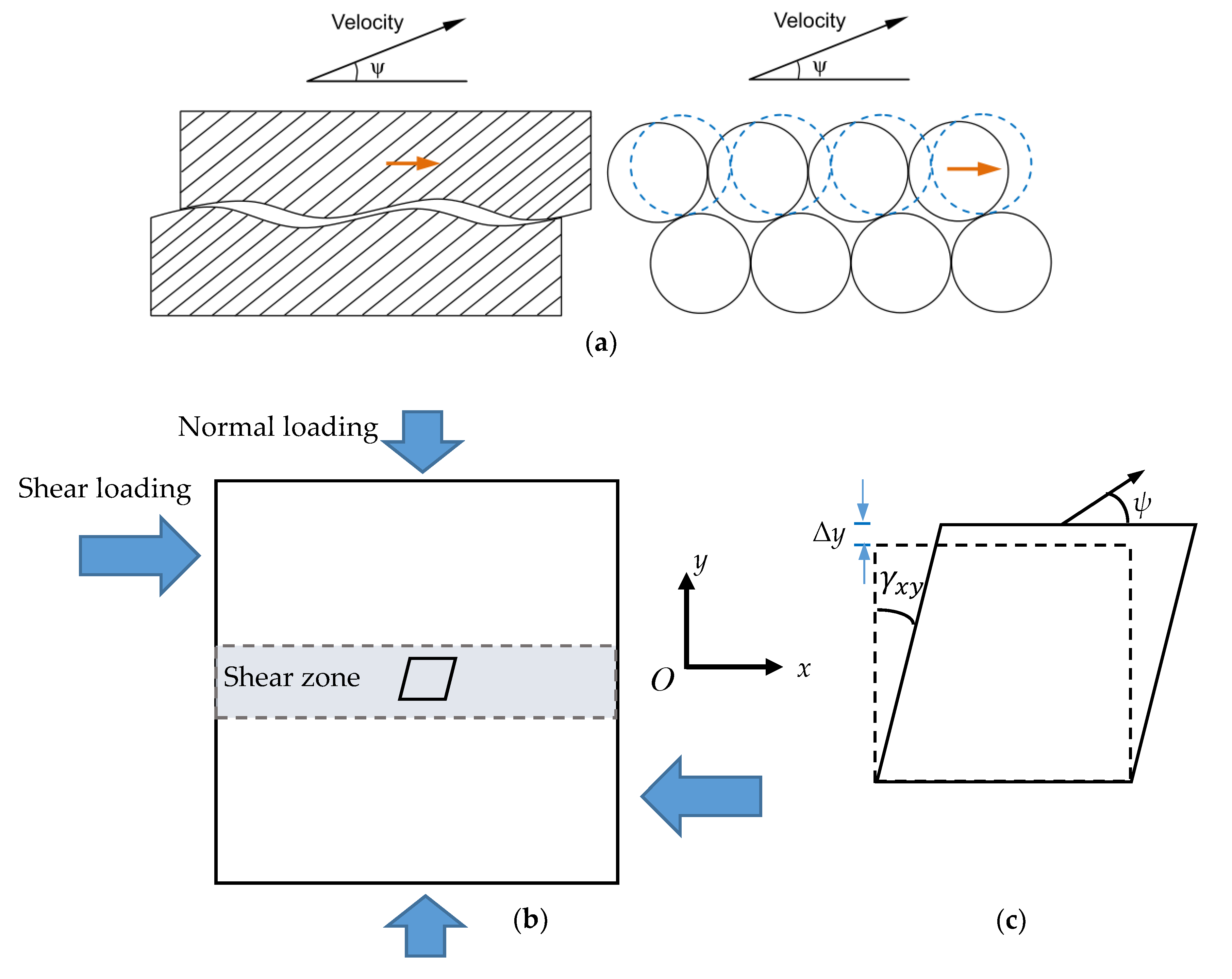
Figure 1. (a) A sketch on the physical meaning of dilation associated with sliding along micro-cracks and particles [34,35] (Reprint with permission [35]; (License Number: 4735211037160, 2010, Elsevier). (b) A sketch of the direct shear experiment on a cubic sample (with the size of 100 × 100 × 100 mm in this study). (c) The physical meaning of shear strain γ and dilation angle ψ with an element from the shear zone.
Energies 13 00122 g001
Figure 2. (a) Schematic map of main geological structures around the Alxa area [22,62]. TMS01, TMS02, NRG01, and NRG02 are four boreholes drilled in TMS and NRG sub-areas. The samples in this study were taken from a quarry near the NRG01 borehole. (b) Cubic granite samples (approximately 100 × 100 × 100 mm) used in the direct shear tests.
Energies 13 00122 g002
Figure 3. DSC-800 direct shear experimental system with a length of 1.6 m and height of 1.8 m.
Energies 13 00122 g003
Figure 4. Shear strength values of the granite samples under direct shear experiments.
Energies 13 00122 g004
Figure 5. Shear stress-normal strain curves and shear stress-shear strain curves of the granite samples under direct shear experiments.
Energies 13 00122 g005
Figure 6. Division of different stress-strain stages of the granite samples under direct shear test.
Energies 13 00122 g006
Figure 7. Sketch of the method for determining the plastic shear and normal strain values.
Energies 13 00122 g007
Figure 8. Plastic shear and plastic normal strain relations of the granite samples under different normal stresses.
Energies 13 00122 g008
Figure 9. Mobilized dilation angle with increasing plastic shear strain under different normal stresses.
Energies 13 00122 g009aEnergies 13 00122 g009b
Figure 10. Variation of fitting coefficients (a) ψ max , (b) ψ r , (c) γ φ , max p , and (d) γ φ , r p at different normal stresses.
Energies 13 00122 g010
Table 1. Sizes of the cubic granite samples and the applied normal stresses for direct shear tests.
NO.Sample Size (mm × mm × mm)Normal Stress (MPa)
N-S198.91 × 99.07 × 99.055
N-S299.12 × 99.16 × 99.153
N-S398.87 × 98.90 × 99.067
N-S499.02 × 99.33 × 99.1411
N-S599.01 × 99.28 × 98.839
N-S699.16 × 98.97 × 99.1113
N-S799.26 × 98.98 × 99.0715
N-S899.22 × 98.88 × 99.1317
N-S999.03 × 99.11 × 99.0915
N-S1099.08 × 99.13 ×98.7715
N-S1198.83 × 98.94 × 98.949
N-S1298.99 × 99.07 × 98.879
N-S1399.22 × 99.09 × 99.183
N-S1499.09 × 99.08 × 99.203
Table 2. Fitted parameters for the dilation angle–plastic shear strain curves under different normal stresses.
Normal Stress (MPa) ψ max   ( ° ) ψ r   ( ° ) γ φ , max p   ( % ) γ φ , r p   ( % ) R2
738.20−0.180.502.200.9150
1139.01−0.120.501.760.9565
1316.811.480.501.830.8517
1523.661.980.502.000.9236
1715.455.360.502.580.9008