A Comparative Study of Energy Storage Systems and Active Front Ends for Networks of Two Electrified RTG Cranes


Abstract
:1. Introduction
- (1)
- A network of two electrified RTG cranes model is developed to investigate and analyse the power flow and peak demand at a port’s electrical network. This will contribute to the limited literature focused on energy savings in network of RTG cranes.
- (2)
- ESS and AFE models are developed and the peak demand reduction and energy cost saving at a port’s electrical network are compared.
2. RTG Crane Network Topology
- Four electrical machines called gantry motors, which move the gantry around the container stack.
- One or two hoist motors which raise the container and are capable of raising containers weighing up to 40 tonnes fully loaded. The hoist motor(s) connect to a spreader through a cable reel by a head block and spreader which can weigh between 8 to 12 tonnes, which can result in a total hoisting weight of 52 tons.
- Two trolley motors which aim to move the cabin and hoisting unit, with or without the full loaded container, across the span of the crane.
2.1. Energy Analysis of RTG Crane System
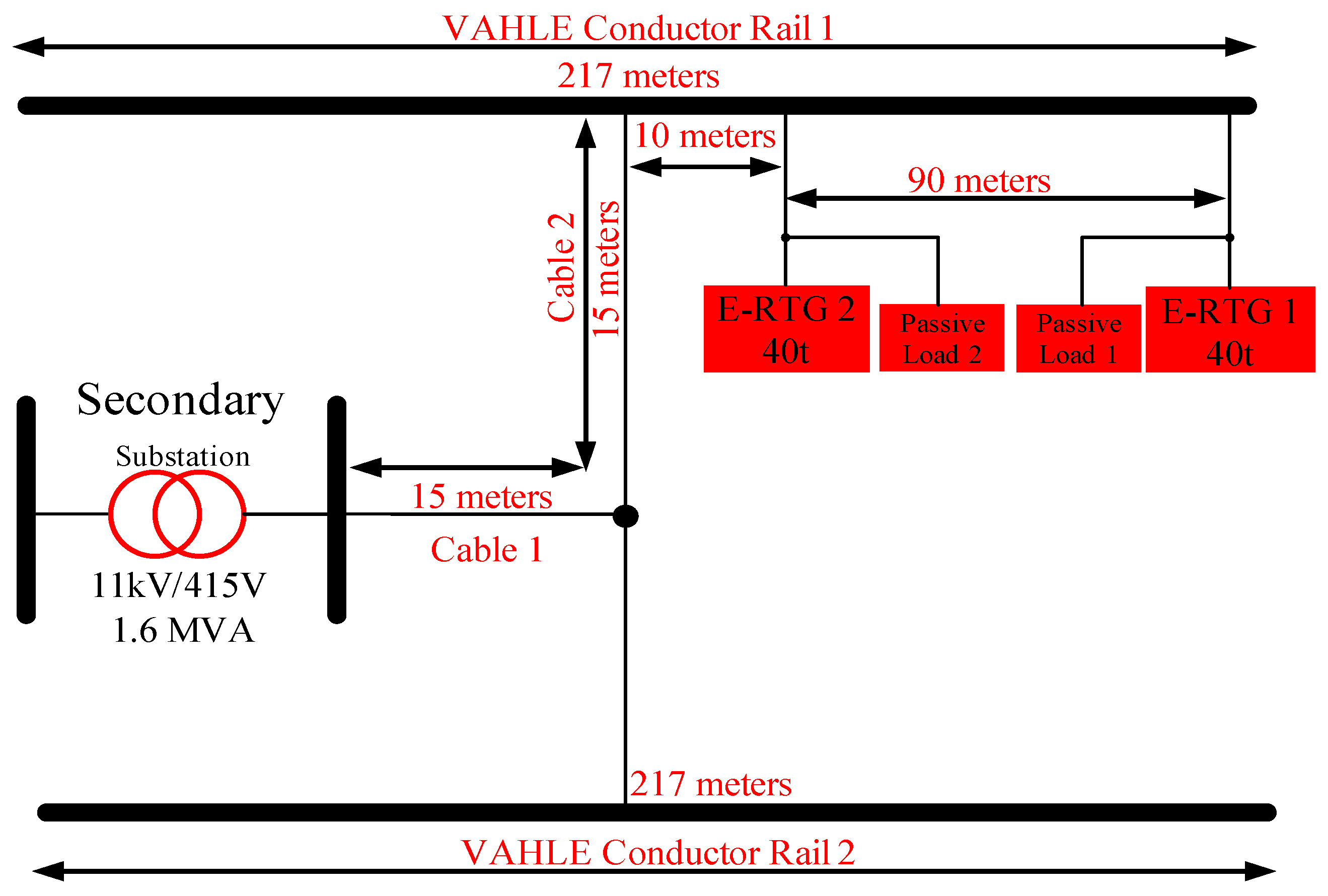
2.2. Network of RTG Cranes: Power System Structure
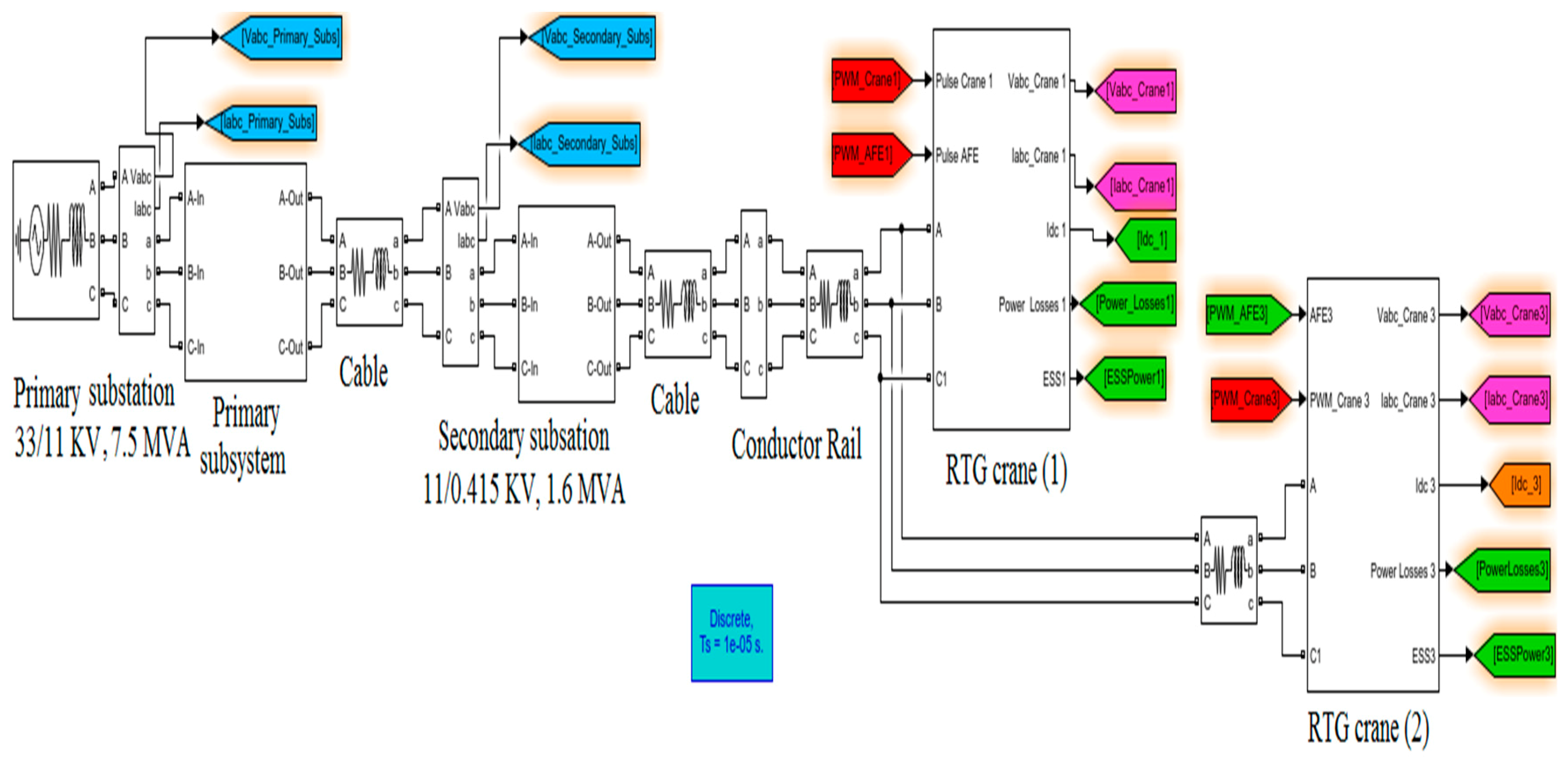
2.3. RTG Cranes Network Modelling
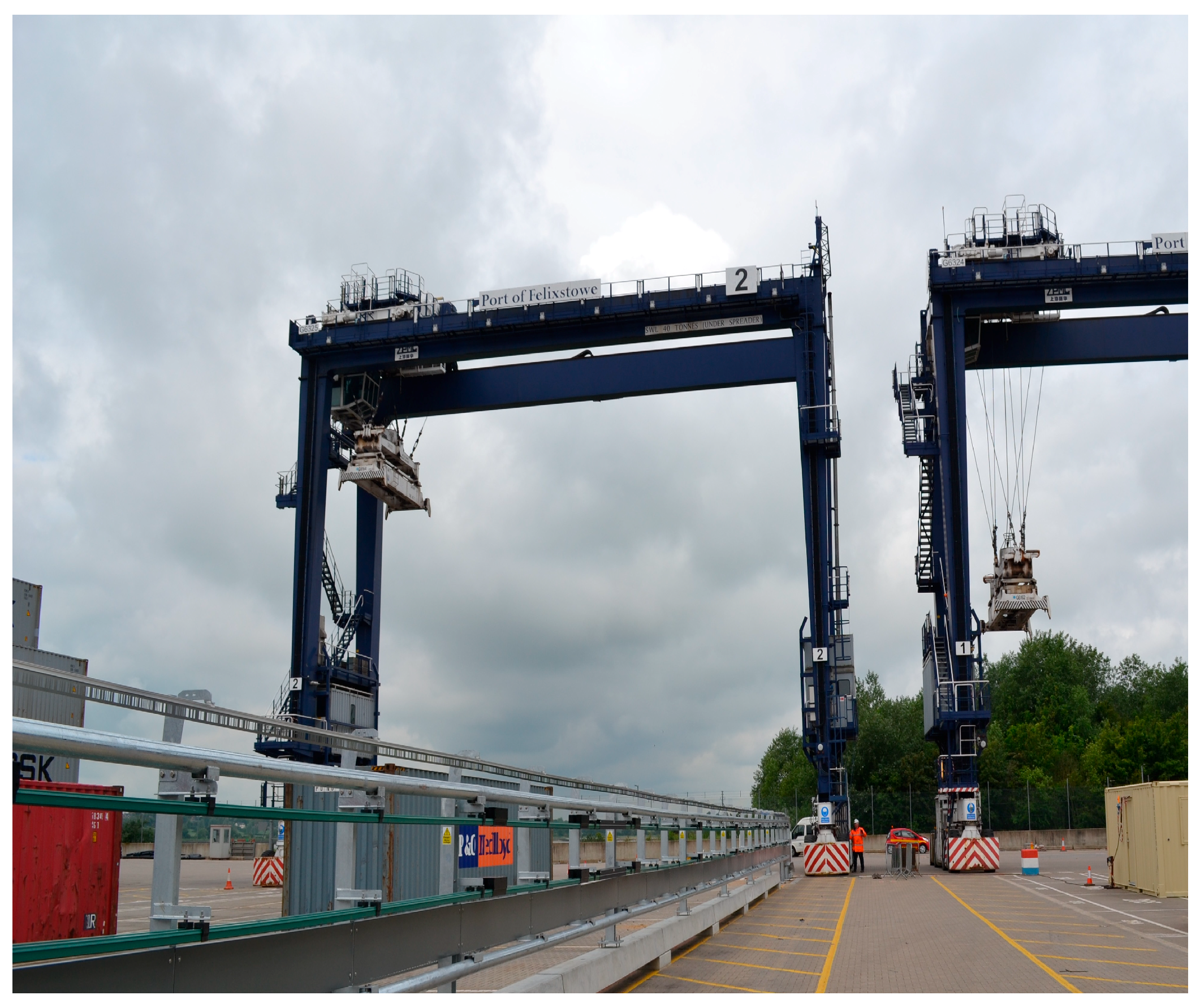
- Primary substation: is an ideal three-phase source for the RTG crane system. The feeder substation (11 kV/ 415 V) provides the necessary power through a low voltage cable which supplies 415V to two cranes via a conductor rail bar. The key numerical parameters of the electrical network components are presented in Table 2 [7]. The parameters of the RTGs network (Section 2.3, Table 2) have been validated using data collected at the Port of Felixstowe, UK.
- RTG crane system: the RTG crane model including the electrical and mechanical components was developed [5,13,14] to study the operating cycle at the Port of Felixstowe. In this study, this model has been extended to include two electrified cranes. The RTG crane system includes induction motors (hoist and gantry) rated at 200 kW and two trolley motors rated 15 kW which are connected to the DC bus.
- The benefits of using either the ESS or AFE on a network of two cranes model were investigated by analysing the energy consumed through the entire network compared to actual demand without using ESS or AFE. In addition, DC/DC converter aims to maintain the voltage level in the RTG crane system and ESS.
- ○
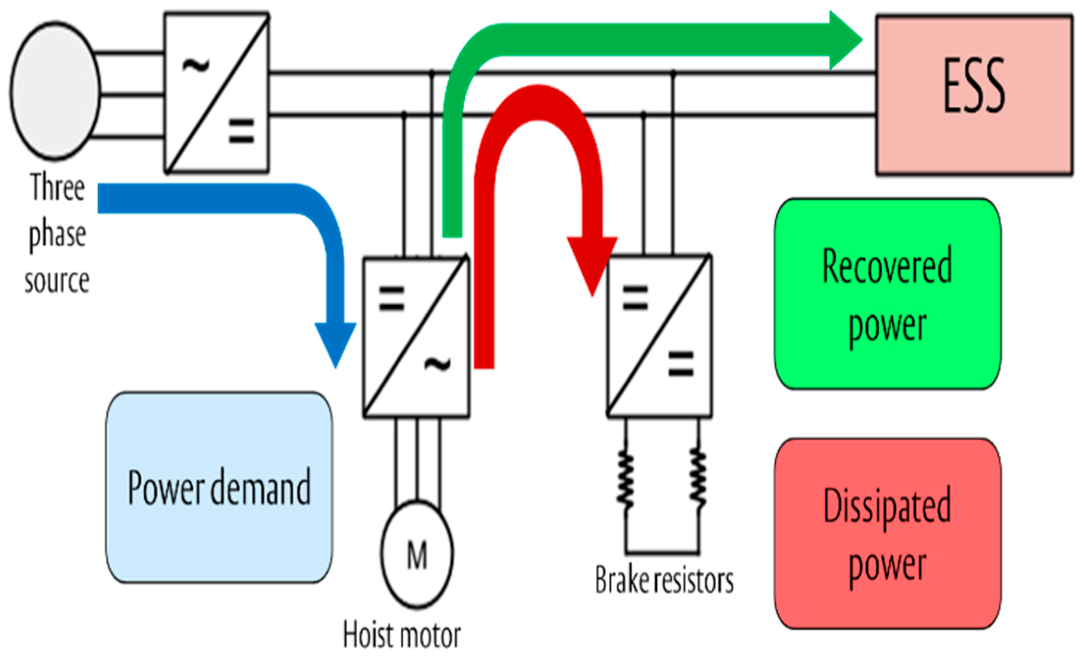
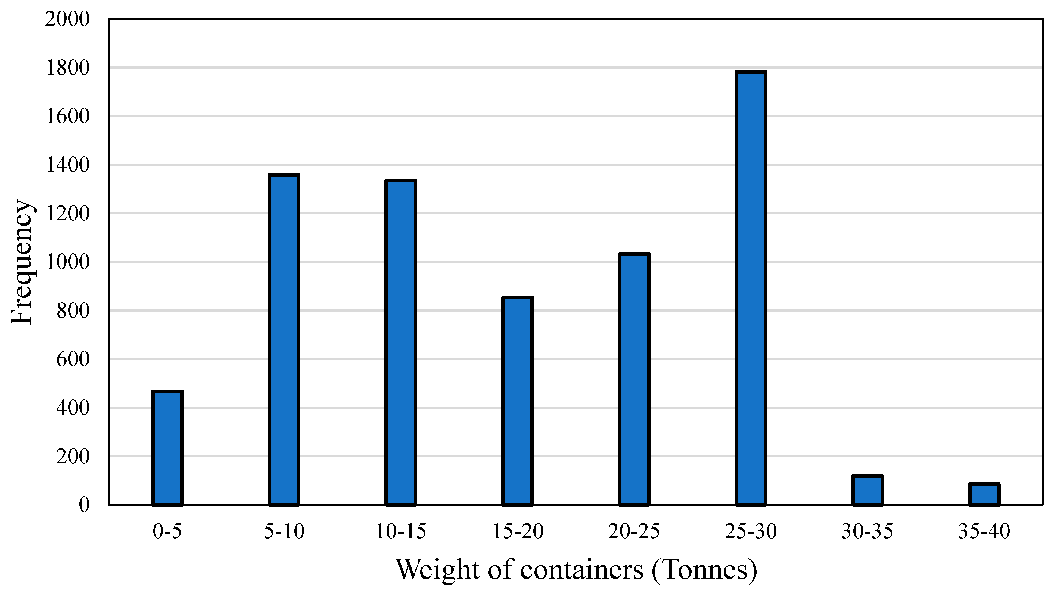
- Energy storage systemsESSs collect energy regenerated during the lowering mode until they are fully charged with the remaining energy being dissipated via dump resistors. The main numerical parameters of the ESS are specified in Table 3. The energy store considered is a flywheel storage device powered by a 150 kW switched reluctance motor and stores up 3.6 MJ of energy [5,13]. In this study a power profile for hoisting the maximum container weight of 40 tonnes is used as it requires the highest level of power to move this container (250 kW). In general increasing the size of the ESS can help to store all regenerated energy so increasing energy saving. However, the higher power density and bigger ESS size will increase the capital cost and for the Port of Felixstowe the average mass of container lifted (including head block and spreader) is only 27 tonnes [13,14]. So this ESS has been sized for lifting this average mass in order to reduce the cost and size of ESS [13,14]. The distribution of container weights at Port of Felixstowe is discussed in Section 4.
- ○
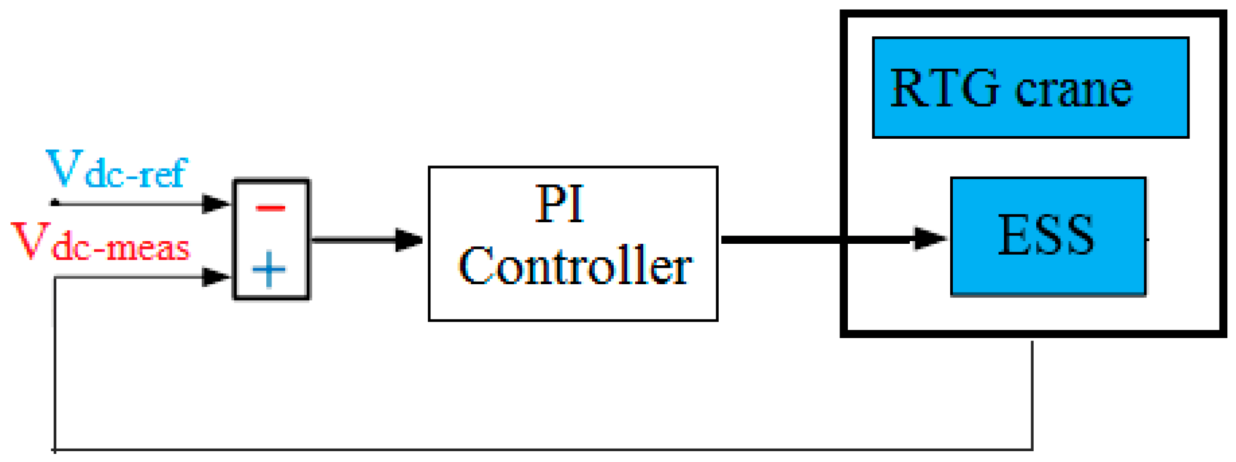
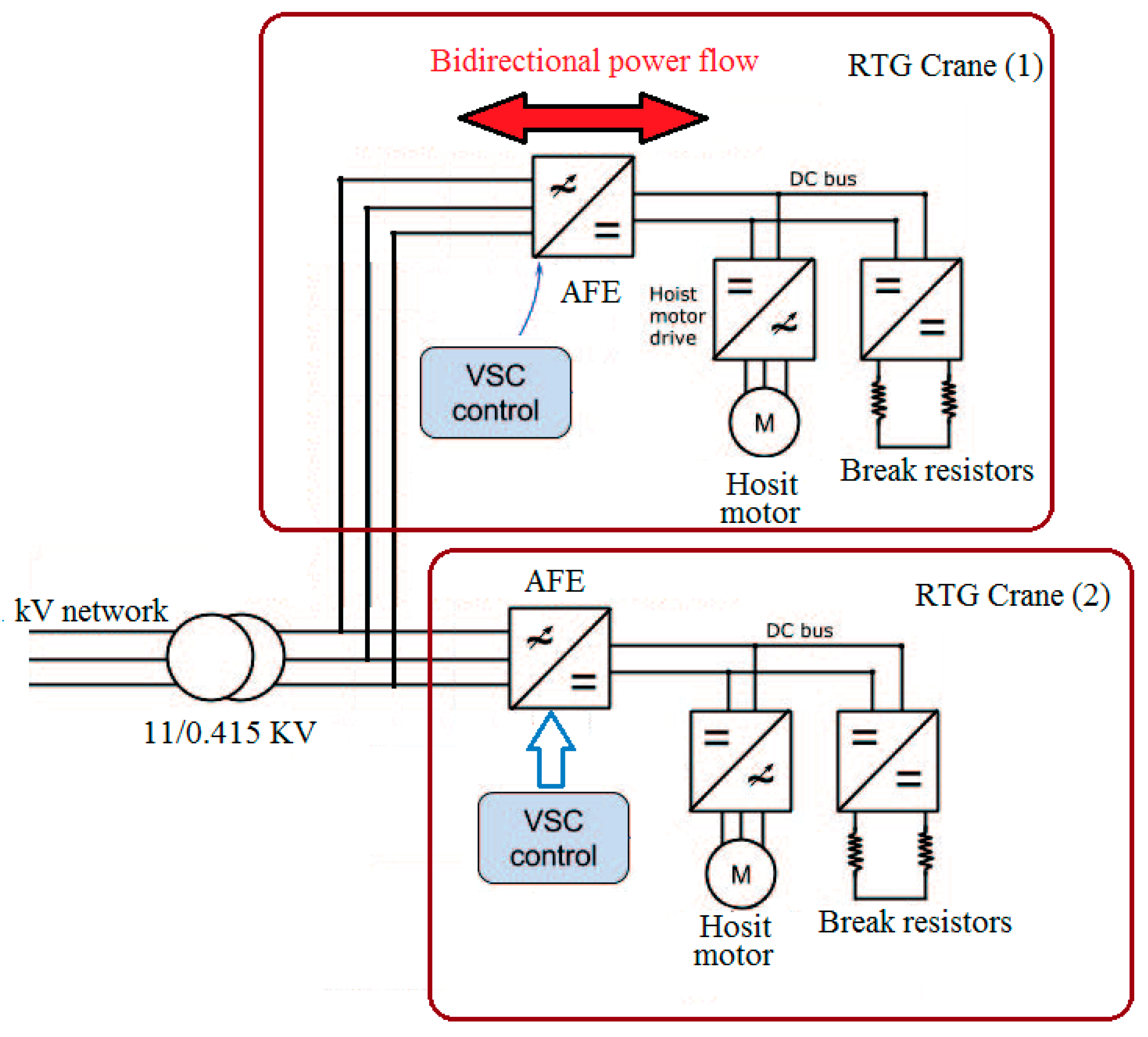
- Active front endsThe AFE as a bi-directional converter which will allow the regenerated power to be fed back into the electrical network of the port terminal and so could be used by another crane. In this paper, the regenerative energy during the lowering mode can be used to reduce the peak demand during hoisting mode if the AFE is modelled as a bi-directional switch [13,14]. The LV power which is fed into the RTG crane is rectified through a diode converter, which converts alternating current (AC) into direct current (DC) power but only allows unidirectional flow. This process aims to protect the electrical distribution side from voltage mismatches or high harmonics produced from the regeneration due to electrical braking in the hoist and trolley motors. The regenerative energy is then wasted as heat in the dump resistors.In order to reduce the wasted energy and increase energy saving, the AFE is modelled using a voltage source converter (VSC) based on a PI controller. The VSC in Figure 6 has been developed to transfer power between the electrical power network and the ccrane’s power system. The control model aims to regulate the DC voltage at each RTG crane bus system by setting a reference value which helps to minimise the regenerative power that goes to the dump resistors and also protects the network from any electrical problems that might occur.
3. RTG Cranes Network: Case Studies
- Two RTG cranes network equipped with an ESS (no AFE). In this model, the AC power can only flow into the DC bus through a diode rectifier power converter [9].
3.1. RTG Cranes Network with ESS
3.2. Active Front End (AFE)
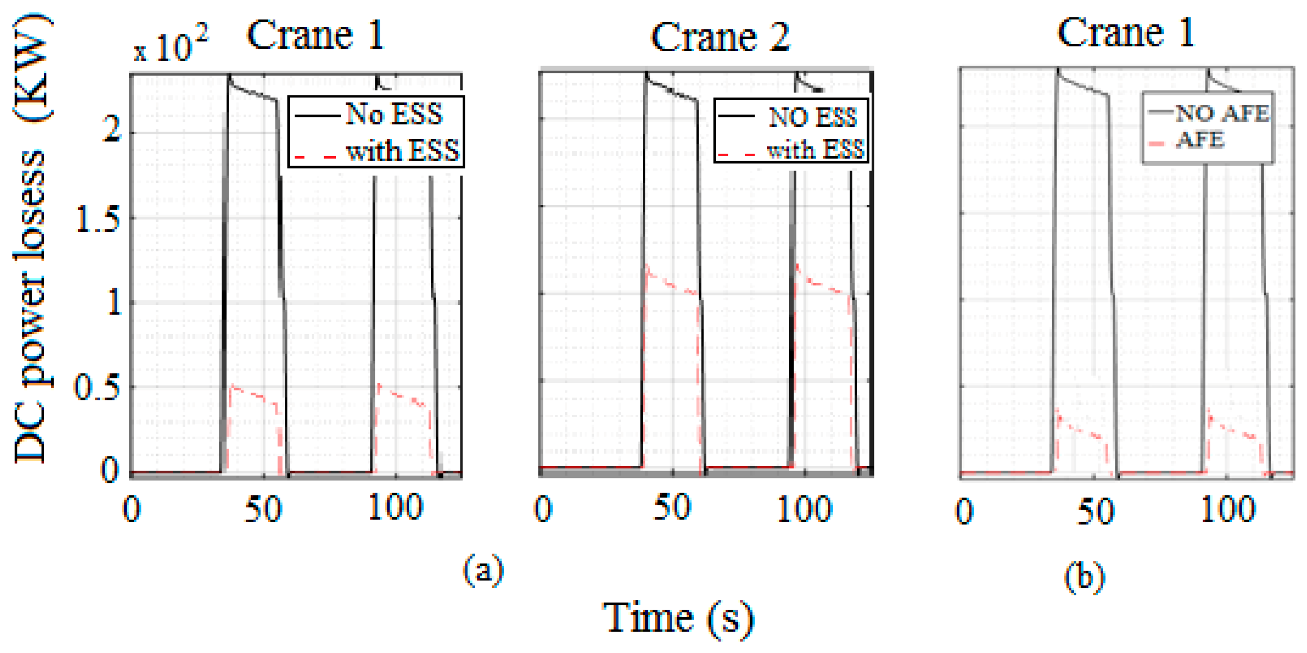
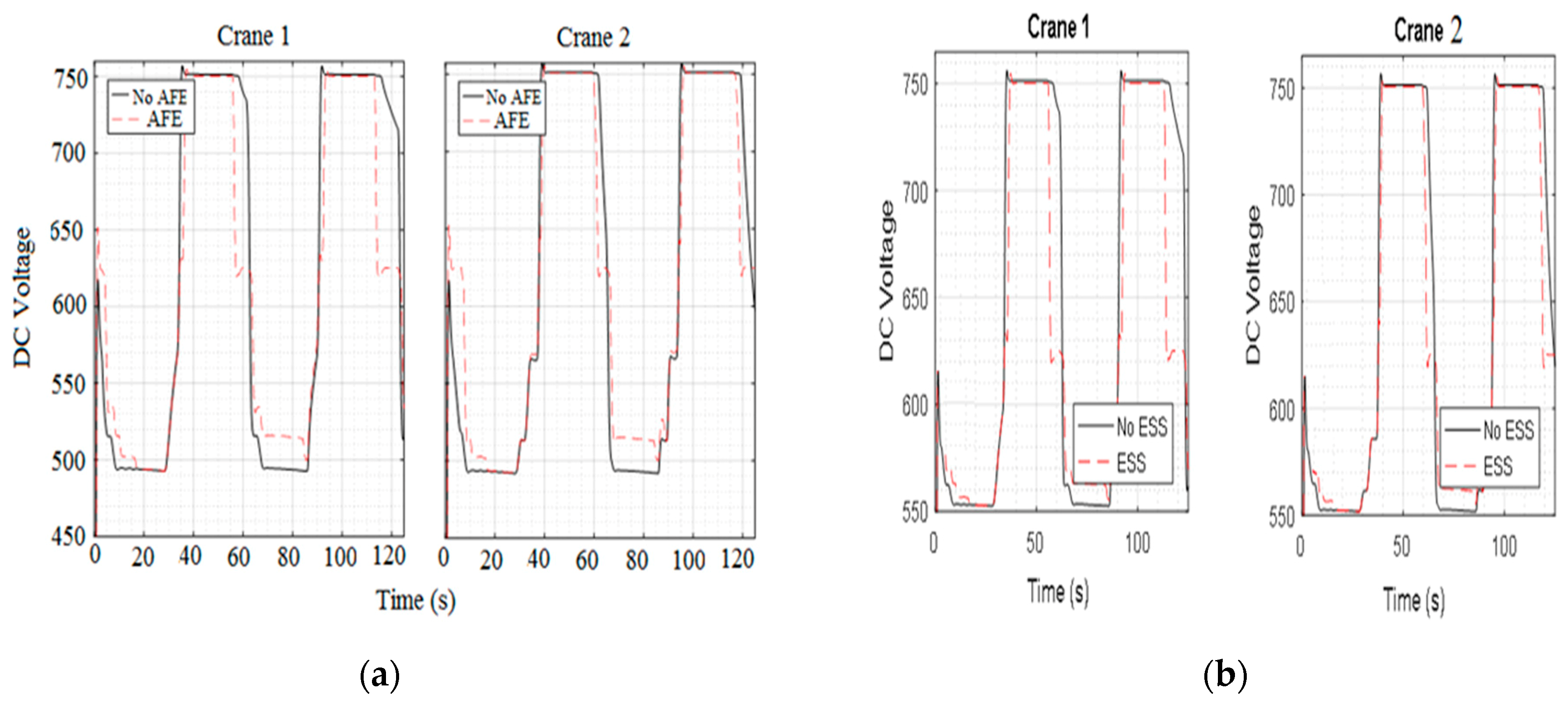
4. Results and Discussion
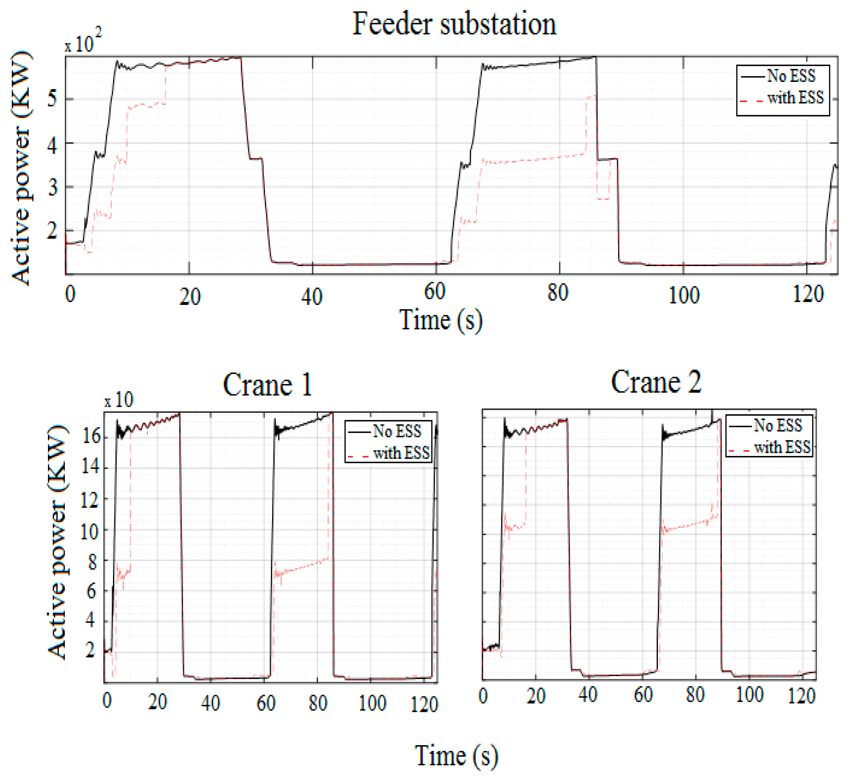
- The first cycle from 0s to 60s. Here, the lifting mode in which energy is consumed during the lifting mode from 2 s to 32 s and lowering mode from 32 s to 60 s.
- The second cycle from 60 s to 120 s. Here, the lifting mode is from 62 s to 92 s and lowering mode from 92 s to 12 s.
5. Conclusions
Author Contributions
Acknowledgments
Conflicts of Interest
Abbreviations and Nomenclature
| RTG | Rubber Tyre Gantry |
| AFE | Active Front End |
| ESS | Energy Storage System |
| WSC | World Shipping Council |
| Carbon dioxide | |
| VSC | Voltage Source Converter |
| DC | Direct Current |
| AC | Alternating Current |
| LV | Low Voltage |
| Power energy storage | |
| Power of the hoist motor | |
| Power losses at network | |
| Power transferred to DC bus system | |
| Power capacitor at VSC system | |
| DC voltage | |
| DC current |
References
- World Shipping Council. Trade Statistics. Online 2018. Available online: http://www.worldshipping.org/about-the-industry/global-trade/trade-statistics (accessed on 8 February 2019).
- World Shipping Council. Ports. Online 2018. Available online: http://www.worldshipping.org/about-the-industry/global-trade/ports (accessed on 8 February 2019).
- International Maritime Organisation. Statistical Resources—UNCTAD Review of Maritime Transport. Online. Available online: http://unctad.org/en/PublicationsLibrary/rmt2016_en.pdf (accessed on 8 February 2019).
- Yang, Y.; Chang, W. Impacts of electric rubber-tired gantries on green port performance. Res. Transp. Bus. Manag. 2013, 8, 67–76. [Google Scholar] [CrossRef]
- Pietrosanti, S.; Holderbaum, W.; Becerra, V. Optimal Power Management Strategy for Energy Storage with Stochastic Loads. Energies 2016, 9, 175. [Google Scholar] [CrossRef]
- Niu, W.; Huang, X.; Yuan, F.; Schofield, N.; Xu, L.; Chu, J.; Gu, W. Sizing of Energy System of a Hybrid Lithium Battery RTG Crane. IEEE Trans. Power Electron. 2017, 32. [Google Scholar] [CrossRef]
- Alasali, F.; Haben, S.; Becerra, V.; Holderbaum, W. Optimal Energy Management and MPC Strategies for Electrified RTG Cranes with Energy Storage System. Energies 2017, 10, 1598. [Google Scholar] [CrossRef]
- Zhao, N.; Schofield, N.; Niu, W. Energy Storage System for a Port Crane Hybrid Power-Train. IEEE Trans. Transp. Electrif. 2016, 2, 480–492. [Google Scholar] [CrossRef]
- Alasali, F.; Haben, S.; Holderbaum, W. Energy management systems for a network of electrified cranes with energy storage. Electr. Power Energy Syst. 2019, 106, 210–222. [Google Scholar] [CrossRef]
- Flynn, M.; Mcmullen, P.; Solis, O. Saving Energy Using Flywheels. IEEE Ind. Appl. Mag. 2008, 14, 69–76. [Google Scholar] [CrossRef]
- Alasali, F.; Luque, A.; Becerra, V.; Holderbaum, W. Energy Reduction and Peak shifting on a Network of Cranes. In Proceedings of the International Conference on Energy, Environment and Economics, Edinburgh, UK, 16–18 Augest 2016; pp. 137–143. [Google Scholar]
- Kim, S.; Sul, S. Control of Rubber Tyred Gantry Crane with Energy Storage Based on Supercapacitor Bank. IEEE Trans. Power Electron. 2006, 21, 1420–1427. [Google Scholar] [CrossRef]
- Luque, A.; Harrison, I.; Pietrosanti, S.; Alasali, F.; Holderbaum, W.; Becerra, V.; Mayer, R. Energy reduction on eRTG. In Proceedings of the IEEE 16th International Conference on Environment and Electrical Engineering (EEEIC), Florence, Italy, 7–10 June 2016; pp. 1–6. [Google Scholar]
- Pietrosanti, S.; Harrison, I.; Luque, A.; Holderbaum, W.; Becerra, V.; Mayer, R. Net Energy Savings in Rubber Tyred Gantry Cranes Equipped with an Active Front End. In Proceedings of the IEEE 16th International Conference on Environment and Electrical Engineering (EEEIC), Florence, Italy, 7–10 June 2016. [Google Scholar]
- Port of Felixstowe. Ship 2 Shore Magazine No 29. Online 2018. Available online: https://www.portof felixstowe.co.uk/press/ (accessed on 8 February 2019).
- Papaioannou, V.; Pietrosanti, S.; Holderbaum, W.; Becerra, V.; Mayer, R. Analysis of energy usage for RTG cranes. Energy 2017, 125, 337–344. [Google Scholar] [CrossRef]
- Harrison, I.; Pietrosanti, S.; Luque, A.; Mayer, R.; Holderbaum, W. Recording and analysing measurements from an RTG crane. Measurement 2018, 125, 284–293. [Google Scholar] [CrossRef]


| Parameter | Value | Unit |
|---|---|---|
| Hoist motor power | 200 | kW |
| Trolley motors power | 2 × 15 | kW |
| Container Weight | 40 | tonnes |
| Spreader mass | 11 | tonnes |
| Section | Components | Rating |
|---|---|---|
| Power source. | Secondary transformer. | 11 KV/415 V 1.6 MVA |
| Distribution | Cable 1 | 0.0754 ohm/km |
| Cable 2 | 0.1240 ohm/km | |
| Conductor rail | 0.0520 ohm/km |
| Parameter | Value | Unit |
|---|---|---|
| Power (s) | 150 | kW |
| Energy | 3.6 | MJ |
| Rated voltage | 625 | V |
| Rated current | 200 | A |
| Network Model Scenario | Above 300 kW | Above 400 kW |
|---|---|---|
| No ESS | 50% | 33% |
| ESS | 36% | 20% |
| AFE | 30% | 12% |
| Network Model Scenario | Percentage of Reduction of Energy Consumption | Percentage of Power Losses Thorough the Brake Resistor |
|---|---|---|
| ESS | 30% | 35% |
| AFE | 47% | 10% |
© 2019 by the authors. Licensee MDPI, Basel, Switzerland. This article is an open access article distributed under the terms and conditions of the Creative Commons Attribution (CC BY) license (http://creativecommons.org/licenses/by/4.0/).
Share and Cite
Alasali, F.; Luque, A.; Mayer, R.; Holderbaum, W. A Comparative Study of Energy Storage Systems and Active Front Ends for Networks of Two Electrified RTG Cranes. Energies 2019, 12, 1771. https://doi.org/10.3390/en12091771
Alasali F, Luque A, Mayer R, Holderbaum W. A Comparative Study of Energy Storage Systems and Active Front Ends for Networks of Two Electrified RTG Cranes. Energies. 2019; 12(9):1771. https://doi.org/10.3390/en12091771
Chicago/Turabian StyleAlasali, Feras, Antonio Luque, Rayner Mayer, and William Holderbaum. 2019. "A Comparative Study of Energy Storage Systems and Active Front Ends for Networks of Two Electrified RTG Cranes" Energies 12, no. 9: 1771. https://doi.org/10.3390/en12091771
APA StyleAlasali, F., Luque, A., Mayer, R., & Holderbaum, W. (2019). A Comparative Study of Energy Storage Systems and Active Front Ends for Networks of Two Electrified RTG Cranes. Energies, 12(9), 1771. https://doi.org/10.3390/en12091771