1. Introduction
Hypersonic vehicle concepts for high-altitude passenger planes or space launchers have been designed based on dual-mode scramjet engines or rocket-based combined cycle (RBCC) engines [
1,
2]. These hypersonic vehicles are initially accelerated by the rocket booster to obtain the sufficient inflow air speed required for start-up of the scramjet engines. Before the scramjet engines operate, the inflow air into the combustor changes from subsonic to supersonic flow, which is called dual-mode. Dual-mode scramjet engines start from a flight Mach number of 2 with shock trains in the isolator [
1]. When the flight Mach number goes beyond 5, the combustion mode changes to the supersonic combustion (or scramjet) mode. Under this transition mode, the isolator is generally used to prevent the shock train from affecting the intake of the vehicle [
3].
For supersonic combustion, it is necessary for some mixers to hold the flame and to blend the fuel-air mixture in the supersonic flow [
4]. These mixers are generally categorized into two types: passive methods and active methods. Passive methods, such as a cavity [
5] and a step [
6,
7], provide a space to hold the fuel-air mixture with minimum flow disturbance to the supersonic flow. Of these, the step mixer is often chosen as the passive mixing device due to its simple geometric structure. However, the recirculation region generated behind a step mixer is considered to be a dead region [
6]. Although there is a circular flow in the recirculation region, it is not sufficient to stir the fuel-air mixture. Furthermore, even though several injectors are equipped to actively inject fuel into the recirculation region, mixing enhancement has not been observed in past studies [
7]. The active methods induce aerodynamic fluctuation to enhance mixing. For instance, Helmholtz resonators [
8] create an acoustic wave and hyper mixers [
9,
10] generate stream-wise vortices by a pressure gradient.
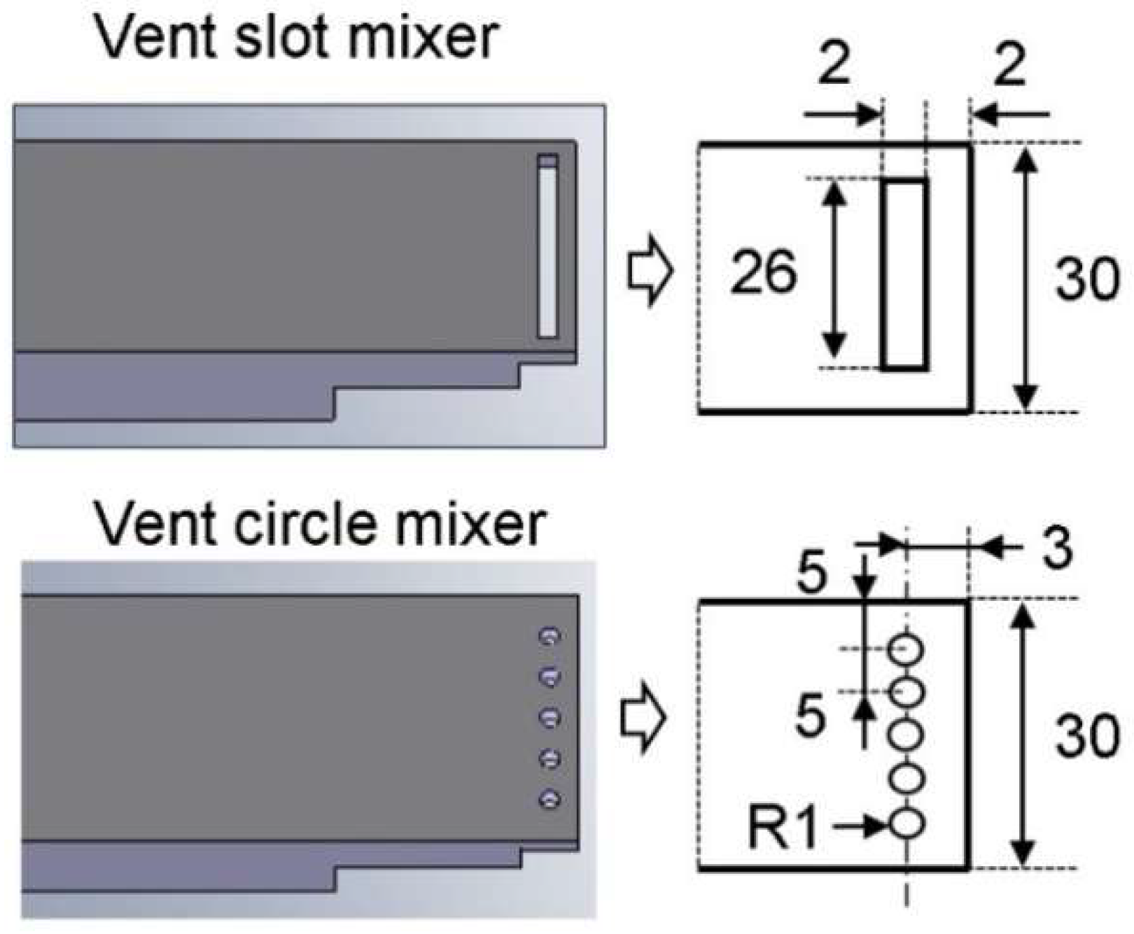
From these mixer models, to enhance mixing in the supersonic combustor, it is considered that a subsonic recirculation region is essential for an active stirring system. It is adequate to select the step mixer for a duct-type combustor to develop a new mixer associated with the concept. Moreover, for the dual-mode scramjet, the upstream area of the step mixer is the isolator and the enlarged downstream duct is used as the combustor. An air blowing device is applied to the step mixer to actively provide air into the recirculation region behind the step mixer. This new mixer is named the vent slot mixer, and this has been already studied in previous work [
11,
12]. The detailed design is discussed later in this paper.
In the previous work [
12], the inflowing air through the slot enlarges the jet plume developed by the normal injection. The relationship between the vent mixer and the normal injection position has an effect on the mixing performance. In addition, the position of the injectors in the recirculation region is an important factor because the fuel (injectant) remnant is dependent on the injection direction in the recirculation region [
13]. Because of this, several injectors were installed in different locations of the recirculation region in the current work. The previous work [
12,
13] utilized the slot to supply air into the recirculation region, but the current work considers the difference between the mixing and combustion performances according to the usage of the slot and circular holes.
3. Results and Discussion
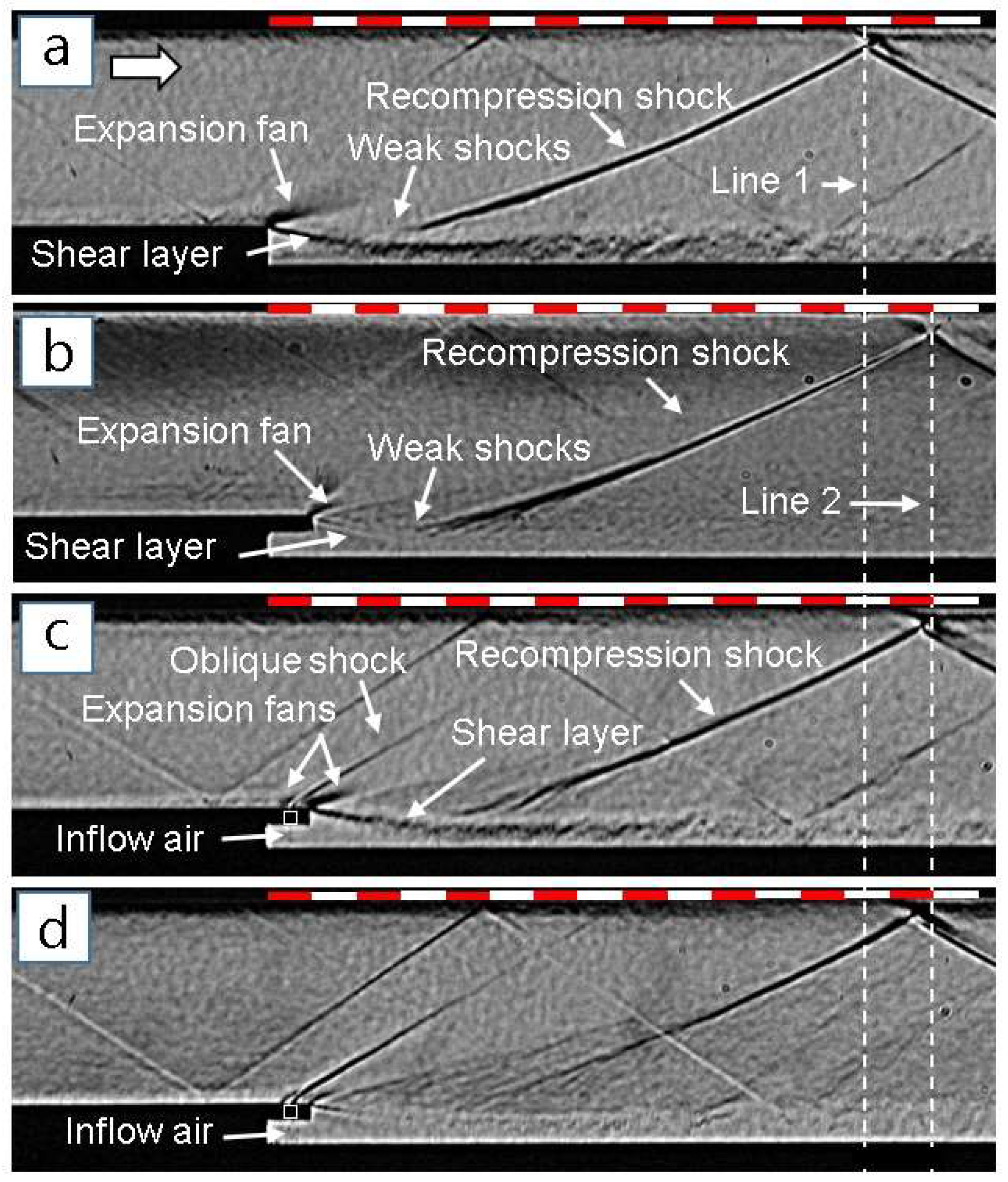
The step mixer has a simple structure to hold the recirculation region behind it, but there is little stirring in this recirculation region. The upstream flow is separated at the edge of the step, and then the flow path is expanded, inducing an expansion fan and shear layer downstream, as shown in
Figure 3a [
6,
16]. A recompression shock is developed from the slope of the shear layer. From the step mixer, a 2 mm thick and 6 mm long block is extended from the step wall. There is a cavity under the extended block. The expansion fan and the shear layer can also be seen in
Figure 3b. Compared with the step mixer in
Figure 3a, the position where the recompression shock collides with the upper wall moves downstream in
Figure 3b. This movement length is about 6 mm, which coincides with the length of the extended block. The extended block plays a role in extending the recirculation region and has little effect on the flow structure development. To provide the main flow into the recirculation region, several holes were perforated into the extended block surface. In
Figure 3c, inflow air through the holes seems to be observed under the extended block. This inflow air stirs the recirculation region, leading to a fluctuating shear layer; weak shocks can be seen from the shear layer [
16]. To increase the inflow air into the recirculation region, a slot was made in the extended block, as shown in
Figure 3d. Compared with the flow structures around the shear layer in
Figure 3c, weak shocks are clearly observed, and a recompression shock is created far from the shear layer surface in
Figure 3d.
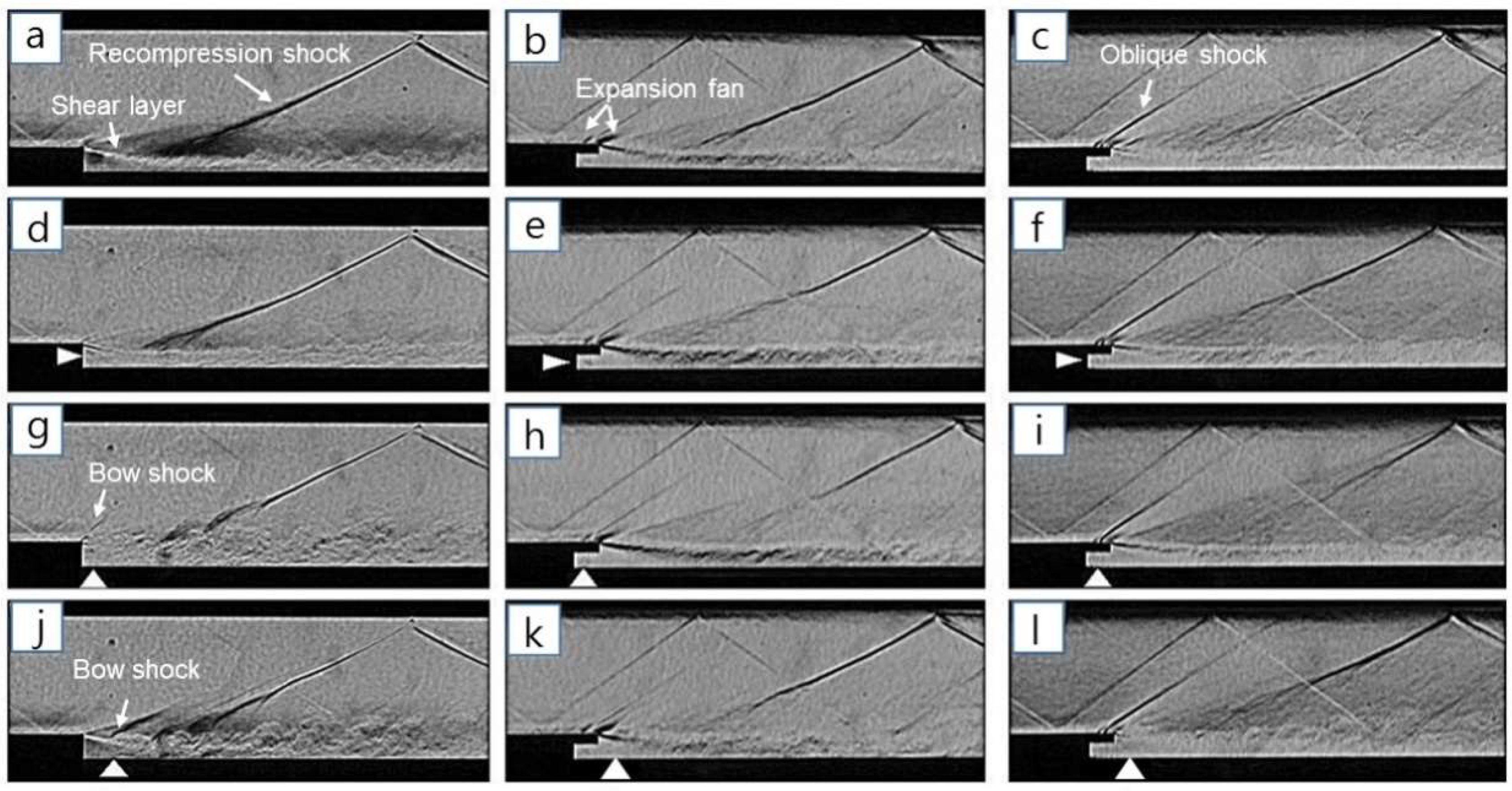
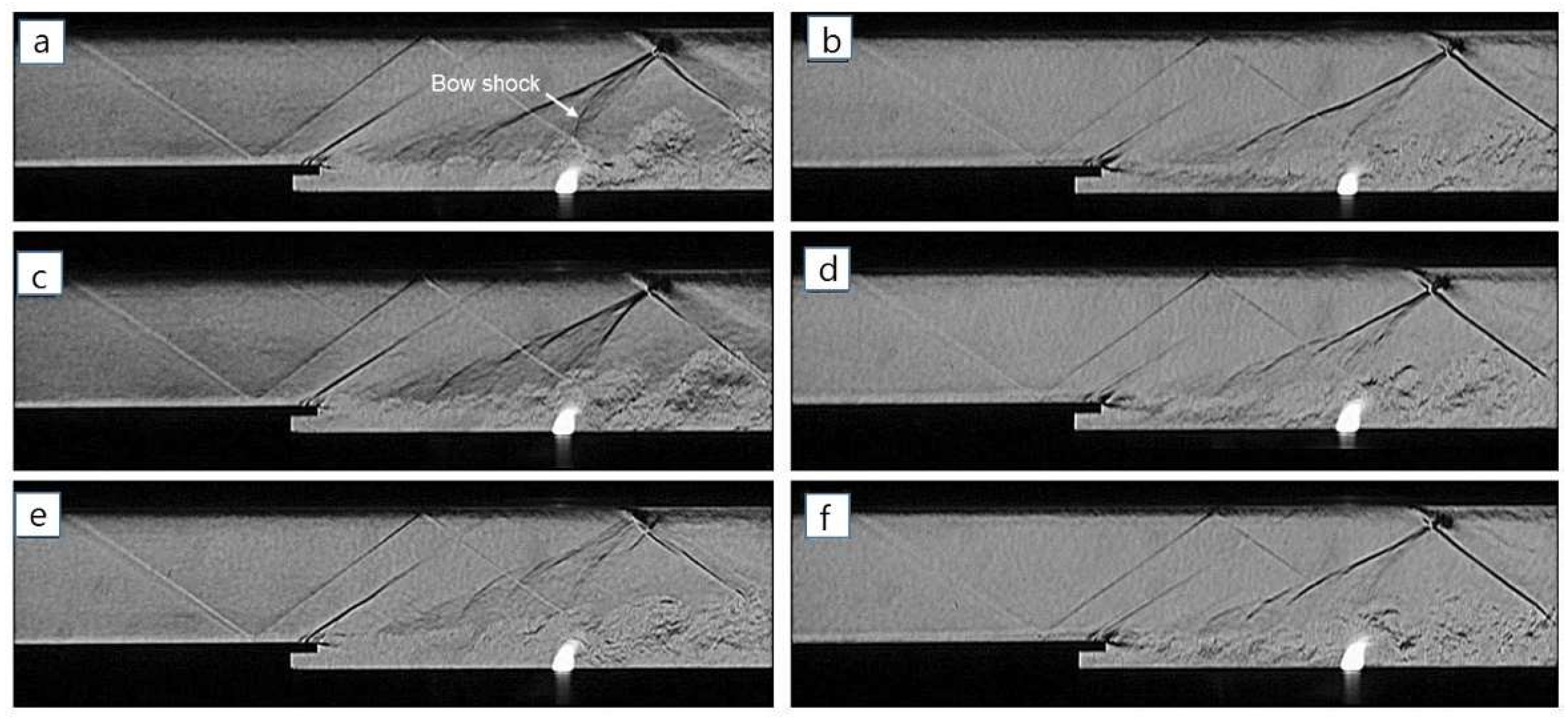
Figure 4 shows a flow field comparison of the three mixer models for
J = 1.6. The hydrogen gas injectant was not burnt in the mixing test for safety reasons, and thus the momentum flux ratio was very low (the equivalence ratio (ER) was about 0.02). The global equivalence ratio was calculated from the ratio of the actual hydrogen-air to the ratio (hydrogen-air) for a stoichiometric process. The step mixer was basically used to compare the vent mixer models in terms of their flow structure. Firstly, for the parallel injection, the injection hardly disturbs the downstream flow structures. The injection thickens the shear layer, and this affects the starting point of the recompression shock, as shown in
Figure 4d. For the VCM, the recompression shock around the shear layer is changed from the single bold line (
Figure 4b) to the Mach waves in
Figure 4e. The VSM shows that the parallel injection slightly affects the shear layer increase in
Figure 4f. The flow field of the VSM is similar to that of the VCM. The normal 1 injection is close to the step wall in
Figure 4g. The injection interacts with the flow structures around the step corner. The downstream shear layer is, thus, fluctuating and the recompression shock shows a sinusoidal movement around the shear layer. The injection rate is very low; a bow shock is faintly seen at the step corner in
Figure 4g. For the VCM, the normal 1 injection conflicts against the extended block and then runs downstream. Therefore, the normal 1 injection shows a similar flow field to the parallel injection, as shown in
Figure 4e,h. For the VSM, on the other hand, the recompression shock near the shear layer disappears in
Figure 4i. It is considered that the inflow air through the slot actively scatters the injection downstream. The normal 2 injector is located behind the extended block of both vent mixers. For the step mixer, the injection penetrates through the slope of the shear layer in
Figure 4j. A bow shock is generated ahead of the injection, inducing fluctuation of the downstream shear layer. However, for both the vent mixers, the bow shock of the injection is not clearly observed in
Figure 4k,l. This is because the weak bow shock is overlapped with the expansion fan at the edge of the extended block. The bow shock scatters the downstream shear layer, similar to the step mixer case in
Figure 4g. Furthermore, the normal 2 injection has little effect on the shear layer growth when considering the recompression shock shape. The shear layer growth behind the mixers weakens the recompression shock development around the shear layer surface.
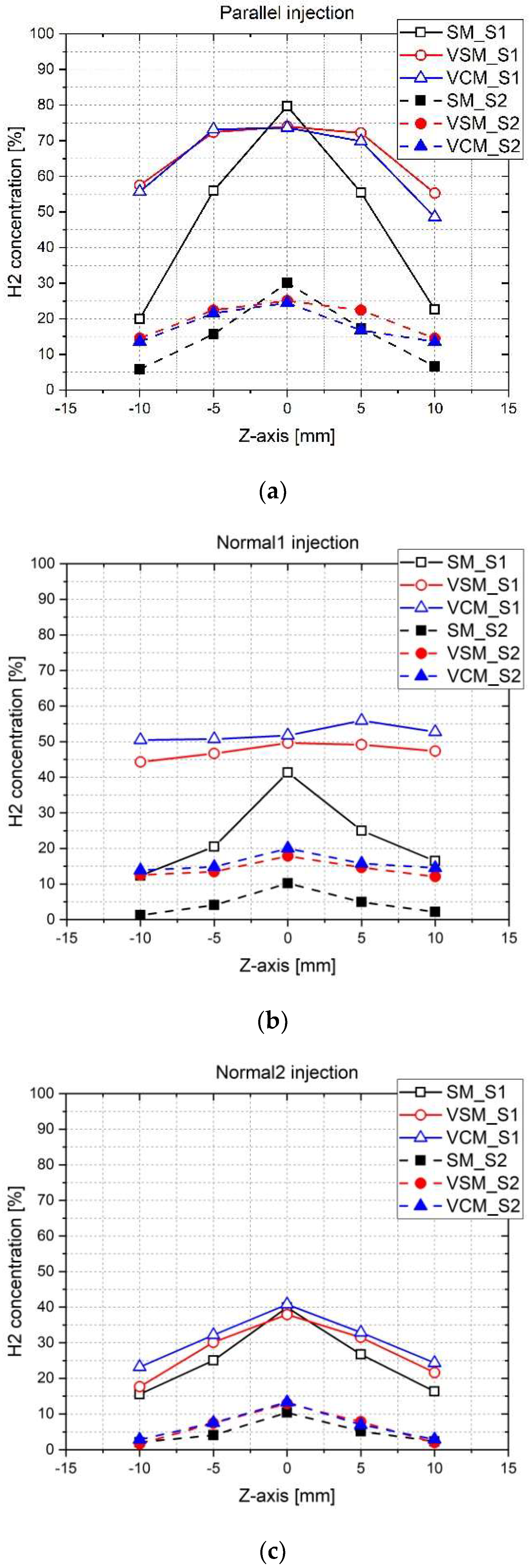
With the Schlieren images, the hydrogen gas concentration was measured from span 1 (S1) and span 2 (S2). For the parallel injection, the step mixer shows a peak value at
Z = 0 and lower values toward the side direction in
Figure 5a. This distribution pattern is sustained in the downstream region (S2). However, both the vent mixers have an even distribution with a high concentration value around the center region along span 1. The concentration around the side region is also relatively high in comparison with that of the step mixer. The inflow air through the slot or the holes disturbs the parallel injection, and this contributes to enhancing the injectant dispersion downstream. For the normal 1 injection, the hydrogen concentration of the step mixer decreases by half of the proportion of the parallel injection case. This is because most of the injectant is thrown out to the main flow and not held in the shear layer, as shown in
Figure 5b. Meanwhile, for both the vent mixers, the normal injection is obstructed by the extended block. Therefore, much injectant can be held in the shear layer and its concentration distribution depicts a highly flat pattern, as shown in
Figure 5b. For the normal 2 injection, three mixer models show the same distribution pattern, as shown in
Figure 5c. For the step mixer, the different normal injector positions have little effect on the concentration distribution, as shown in
Figure 5b,c. Furthermore, the normal 2 injection is hardly affected by the inflow air of both the vent mixers. From the hydrogen concentration data, as a result, it is considered that the relationship between the injection position and the slot (or the holes) position plays a significant role in the mixing process in the shear layer.
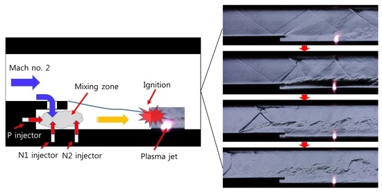
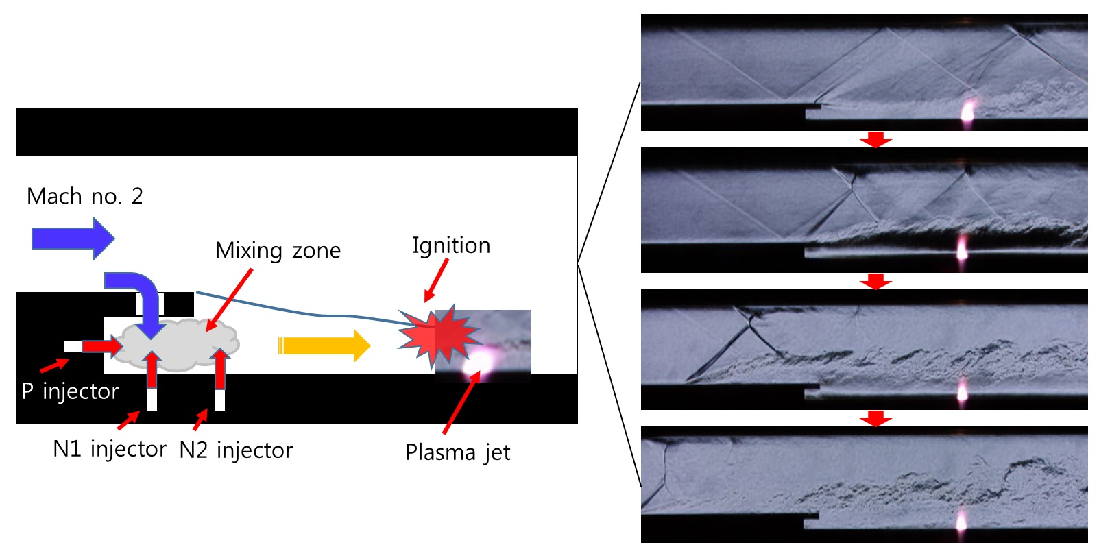
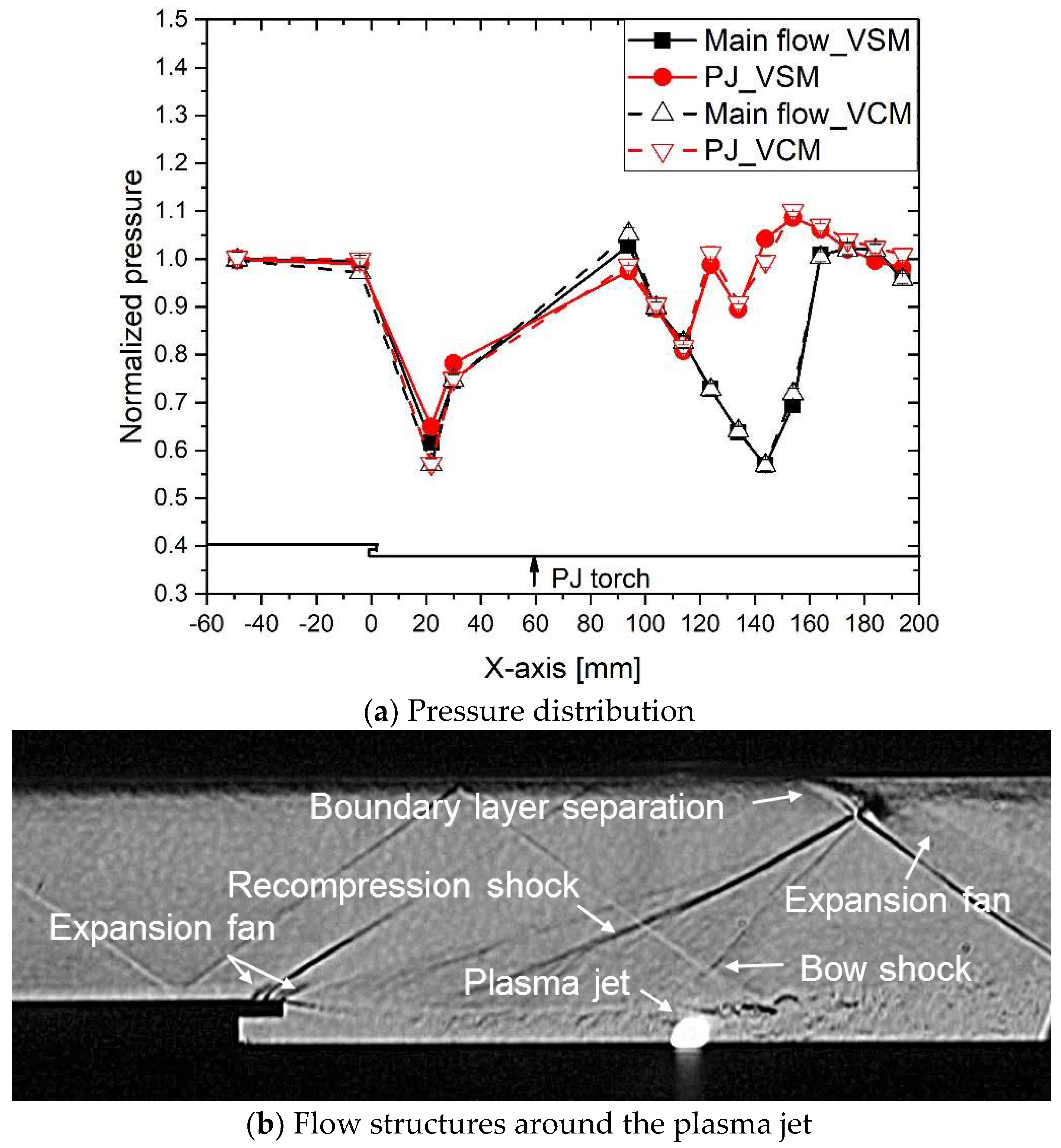
Figure 6a shows the effect of the PJ used as the hot source in the flow field. Without the PJ injection, the pressure drops sharply in the expansion region behind the vent mixer and the pressure recovers through the recompression shock. The downstream pressure behind the PJ torch shows a large up and down pattern, because the recompression shock also moves toward the downstream region. When the recompression shock collides against the upper wall, the boundary layer is separated, leading to expansion fan development and the reflected recompression shock toward the lower wall in
Figure 6b. The reflected recompression shock moves continuously toward the lower wall until it disappears downstream. This kind of flow structure, induced by the recompression shock, induces the pressure variation around the boundary layer in
Figure 6a. When the PJ, which is the hot jet plume in
Figure 6b, is injected, the downstream pressure increases and a pressure fluctuation, due to the recompression shock and a bow shock, can be seen in
Figure 6a,b. To sum this up, the PJ has little effect on the upstream pressure, and the downstream pressure behind the PJ torch is mainly affected by the recompression shock.
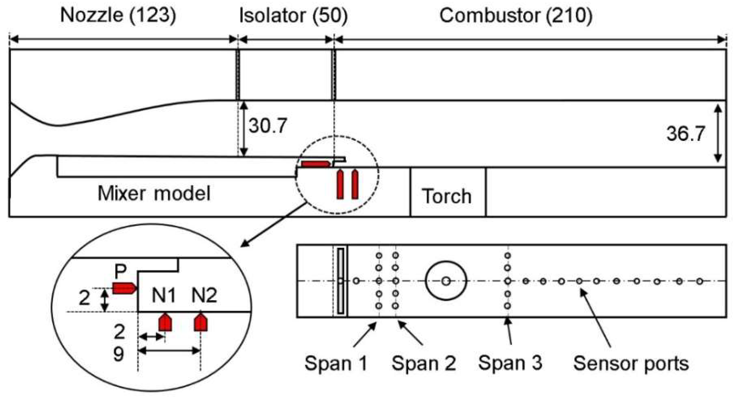
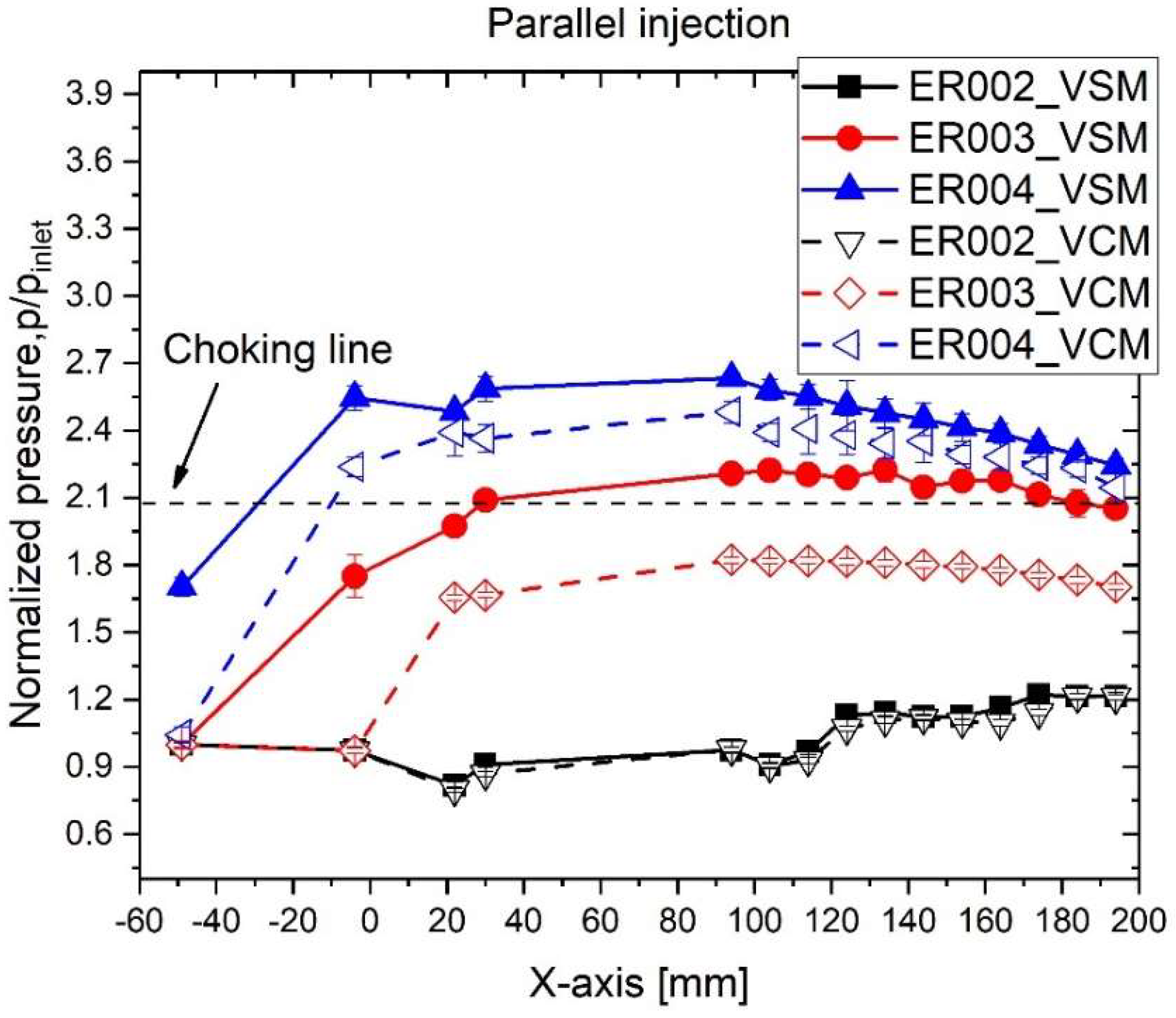
The isolator of the duct-type combustor is designed using Billig’s formula, and the pressure ratio (
Pout/
Pin) is about 2:1 in our case. A pressure ratio above 2:1 indicates that the flow is thermally choked, as shown in
Figure 7. The thermal choking means that, for supersonic flow, heat addition causes the decrease of the Mach number towards unity [
17]. For ER = 0.02, the combustion pressure distributions of the VSM and the VCM show the same pattern, which matches the hydrogen concentration distribution in the mixing test, shown in
Figure 5a. As the ER increases, the VSM has a higher combustion pressure than the VCM. The combustion can be held in the hot region for forced ignition under the cold flow condition. For our case, hydrogen was burned in the PJ and not ignited in the cold main flow. In this sense, for the same ER, the VCM scatters the hydrogen more toward the span-wise direction so that it is not burned by the PJ compared with the VSM. For ER = 0.02, the combustion is very weak, so the upstream pressure of the PJ is not affected, and the recompression shock can be still seen, as shown in
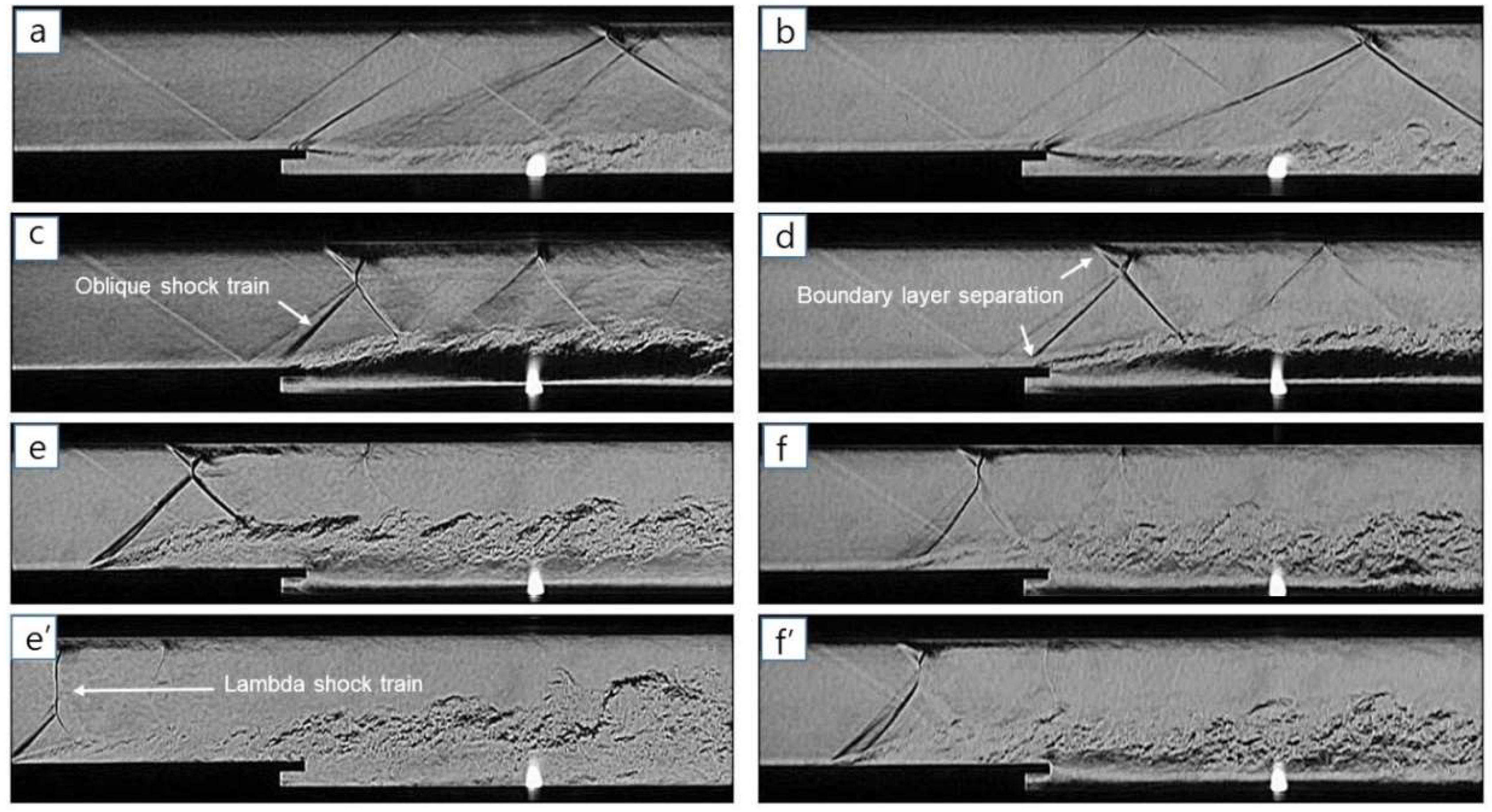
Figure 8a,b. For ER = 0.03, the combustion becomes stronger and induces boundary layer separation around both the vent mixers, as shown in
Figure 8c,d. The combustible region is restricted around the lower wall with the hot source due to the cold main flow. For this reason, boundary layer separation first develops from the lower wall and then the upper boundary layer separation follows, which contributes to the asymmetric oblique shock train. The pressure ports in the isolator are embedded on the upper wall. The combustion pressure of the VSM is higher than that of the VCM, as shown in
Figure 7. The oblique shock train of the VSM is strong and the upper boundary layer separation goes close to the isolator outlet, as can be seen in
Figure 8. For ER = 0.04, the VSM shows the unstart condition. The pressure increases in the nozzle outlet and all pressure ratios exceed 2:1, as seen in
Figure 7. Under the unstart condition, the shock train intrudes into the nozzle exit and the downstream flow becomes subsonic. However, in the suction-type test facility, the main flow recovers to supersonic flow due to the vacuum suction, which comes to be the unstart again. This process is quickly repeated, as shown in
Figure 8e,e′. The oblique shock train goes toward the nozzle exit, as shown in
Figure 8e. After the shock train intrudes into the nozzle, the lambda shock train can be seen, as shown in
Figure 8e′. For the VCM, the shock train displays upstream and downstream movements in the isolator and does not go into the nozzle, as shown in
Figure 8f,f′.
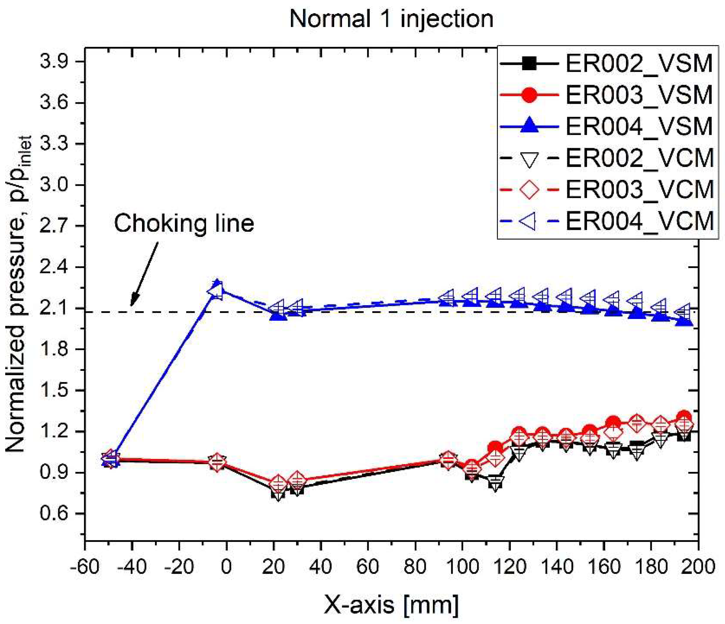
In the case of the normal 1 injection, both the vent mixers show similar combustion pressure patterns, as seen in
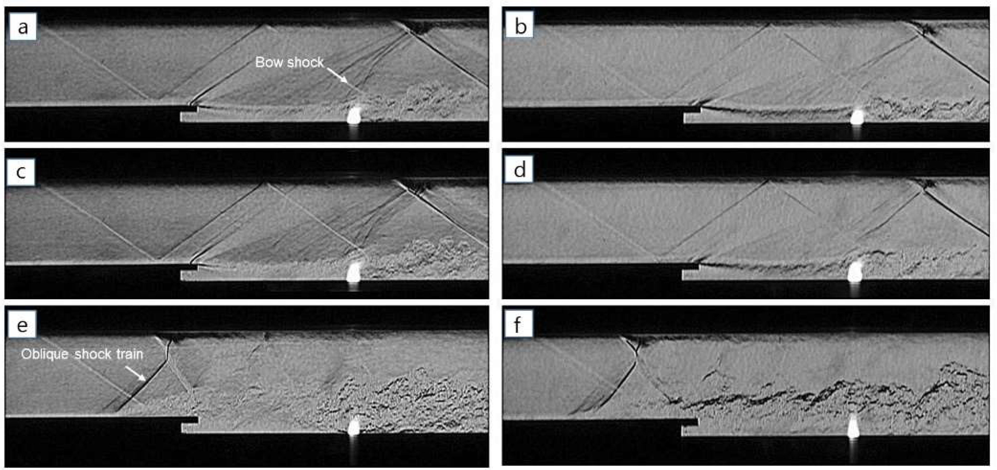
Figure 9. For ER = 0.02 and 0.03, the downstream combustion pressures are low and are affected by the recompression shock. In
Figure 10a–d, the shock structures, such as the recompression shock and the bow shock, can still be seen around the upper wall region and the four figures show little difference in the flow fields. For ER = 0.04, the flow is thermally choked in the combustor and the shock train exists in the isolator for both the vent mixers. This can be seen in
Figure 10e,f. Although the normal 1 injection results in good mixing performance, as seen in
Figure 5b, the amount of hydrogen supplied into the PJ is reduced by the wide dispersion, contributing to the weak combustion. However, as the combustion is strong enough to affect the side region, the combustion pressure rises sharply.
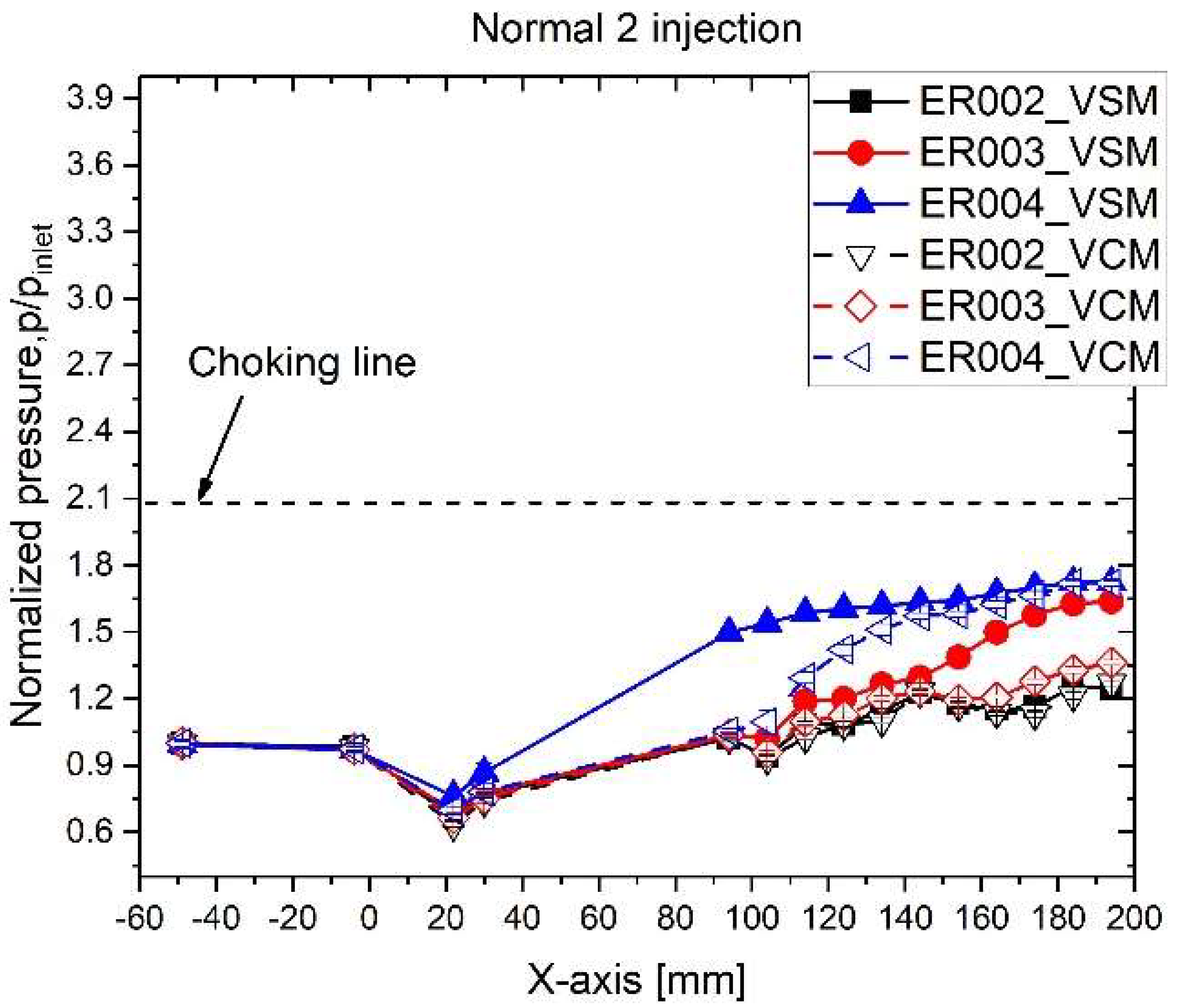
In
Figure 11, for the normal 2 injection, there is no thermal choking for all ER ranges. For ER = 0.02, both the vent mixers show the same combustion pressure pattern. For ER = 0.03, the VSM is superior to the VCM in the downstream combustion pressure. In
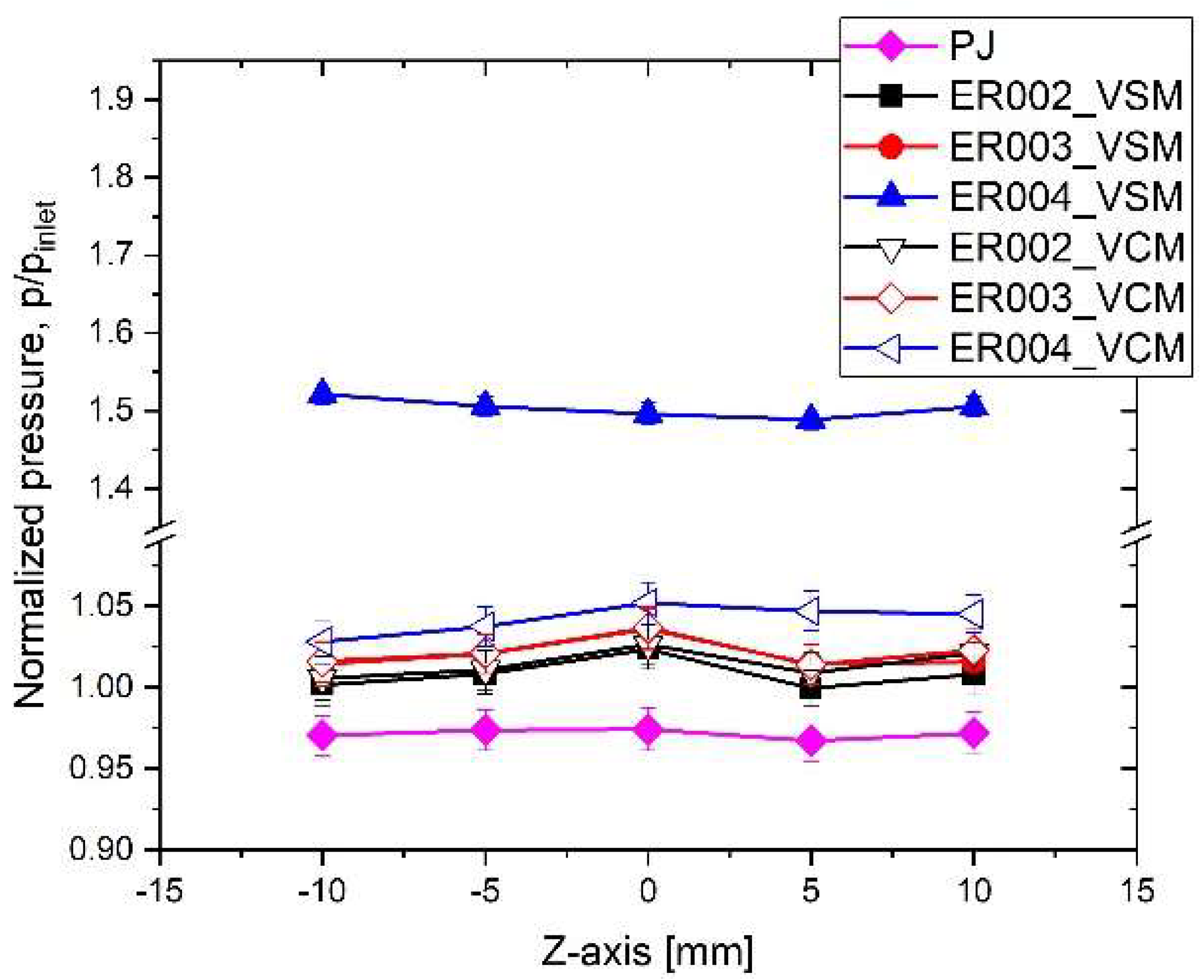
Figure 12, the recompression shock is observed in all figures, and the downstream jet plume fluctuates intensely according to the ER increase. The span-wise combustion pressure measured from span three is displayed in
Figure 13. The PJ without combustion shows a flat pressure distribution. For ER = 0.2 and 0.3, the weak combustion has a somewhat high pressure in the center region relative to the surrounding pressures. This is considered to be owing to combustion only occurring weakly in the PJ. As mentioned earlier, the normal 2 injection supplies most of the hydrogen gas into the cold main flow, so it will not be burned by combustion. Because of this, combustion occurs just in the jet plume, due to the small quantity of hydrogen gas. As the injection rate increases, the span-wise combustion pressure rises evenly.
In order to compare the overall combustion performance, each combustion pressure difference between the combustion pressure (
Pcom) and the pressure without combustion (
PPJ) is summarized and normalized by the total pressure (
Ptotal). The combustion pressure increment (Δ
P) is evaluated by:
If the combustion pressure increment exceeds unity in
Figure 14, the combustor enters the thermal choking condition and the shock train is developed in the isolator. In the one-dimensional Rayleigh flow condition [
17], the heat addition (or equivalence ratio) required to choke the flow is dependent on the inflow total temperature. For instance, if the inflow total temperature is about 1047 K, which corresponds to a flight Mach number of 4 [
18], the equivalence ratio of hydrogen gas for choking at the constant duct exit is about 0.1 [
19,
20]. In our case, the inflow air is not hot enough to be combustible but instead is ambient air, so the equivalence ratio for choking the flow is about 0.03 for the inflow total temperature of 296 K. In this sense, for ER = 0.03, thermal choking begins in the case of the parallel injection for the three mixer models. This indicates that the hydrogen is mostly burned in the combustor and the combustion efficiency is high. In the mixing test, the remaining hydrogen volume of the normal 1 injection of the two vent mixers is secondary to the parallel injection in
Figure 3. Therefore, for ER = 0.04, the combustion pressure increments of the normal 1 injection for the two vent mixers go beyond unity, as shown in
Figure 12. All injection cases show thermal choking in the combustor for ER = 0.06.


