1. Introduction
The increasing interest for multiphase drives in real applications [
1,
2], added to the complexity of designing appropriate controllers for these multivariable systems, have put the emphasis on model predictive control methods (MPC) and particularly on the finite control set MPC (FCS-MPC) [
3]. The FCS-MPC is a kind of fast direct control method that commands the power converter without using pulse width modulation (PWM) blocks, providing excellent transient performance and lower switching frequency than PWM blocks with conventional proportional-integral controllers (PI-PWM), under comparable conditions [
4,
5]. This issue has been extensively investigated in [
6], where FCS-MPC and PI-PWM current controllers are compared, concluding that the FCS-MPC provides a faster transient evolution at the expense of a lower steady-state performance, something that is, in general, inevitable in multiphase drives due to the existence of nonflux/torque producing current components. Additionally, the simple and multi-objective formulation of the FCS-MPC algorithm makes it an excellent option in multiphase drives, being that five-phase induction machine (IM) is one of the most investigated configurations [
7].
However, an important drawback appears in the FCS-MPC implementation, which is the high current/voltage harmonic content. This problem has been recently examined in [
8], concluding that the fixed-time discretization nature of the control method, along with the fact that only one of the possible power converter states is applied during each sampling interval, favour the appearance of not only high magnitude harmonics but also inter-harmonics and electrical noise. Some recent solutions based on the selective harmonic elimination concept can reduce harmonics of the integer multiples of the fundamental frequency [
9,
10], but they do not cancel inter-harmonics and electrical noise.
A careful design of the cost function, which represents the control objectives of the FCS-MPC, can also help in the reduction of the harmonic content [
11]. For example, a precise tuning of the weighting factors that weight each control objective can be decisive [
4,
6,
12], as well as the limitation of the commutation frequency in the converter by the restriction of the available changes in the switches of the converter’s legs [
13]. However, these techniques generally increase the controller complexity and the computational requirements, another important handicap in the application of FCS-MPC methods to multiphase drives. Furthermore, they can lead to suboptimal solutions when not all the possible control actions are taken into account. In addition, there exists an interdependence between the harmonic content and other control aspects, such as the switching frequency or the operating point, which can be seen as fundamental trade-offs that the cost function design cannot completely bypass [
14].
A quite different alternative for the harmonic mitigation consists in adding a modulation stage in the FCS-MPC algorithm [
15] or applying more than one switching state of the power converter during the same sampling time [
16], which is in essence a kind of modulation. However, these techniques produce higher switching frequencies than conventional FCS-MPC methods when identical sampling time is imposed, and could increase the high computational cost of the predictive controller.
The use of simpler natural solutions can alleviate the harmonic problem that the previously cited techniques suffer. One of them is the newly proposed variable sampling time lead pursuit controller (VSTLPC) [
17], which introduces the concept of non-uniform sampling time as a new degree of freedom in the model-based predictive technique. In this way, both the switching state of the power converter and its time of application are optimally selected between all the possibilities without the necessity of a cost function and with an affordable computational cost. A different alternative consists of the improvement of the predictive model, since the selected control action depends on it. In this context, the observer theory has been recently incorporated in the FCS-MPC for the estimation of non-measurable parts of the system model, leading to significant improvement of the system performance. Rotor current observers based on the Luenberger theory and Kalman filters are usually applied in the FCS-MPC current control of multiphase IM replacing the traditional backtracking procedures [
18,
19]. This work focuses on the study of VSTLPC and rotor-current observers as natural ways to reduce the harmonic distortion and electrical noise in predictive controllers. The basis of compared techniques will be reviewed in
Section 2 and
Section 3, where a five-phase IM drive is used as a well-known case example of multiphase drives. Experimental results to corroborate the utility of these techniques are presented in
Section 4, while the obtained conclusions are summarized in the last section.
2. Rotor Estimation in FCS-MPC Techniques: The Observer Approach
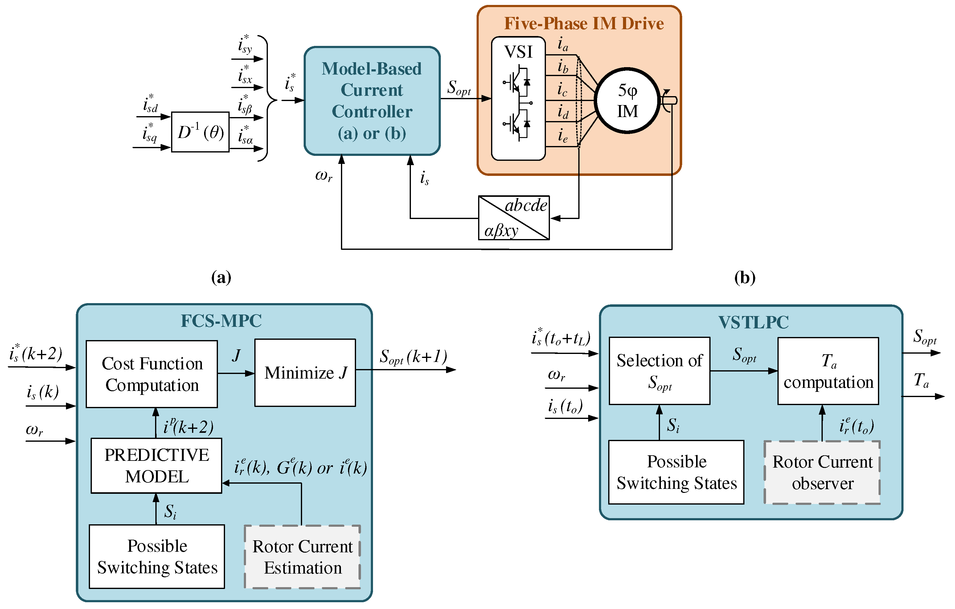
Considering a five-phase IM drive supplied by a two-level five-phase voltage source inverter (VSI) as the controlled system under study, the general scheme of the applied FCS-MPC current control is illustrated in
Figure 1a. The main goal is to find the switching state (
) that forces the stator currents (
) to follow the references (
). To this end, a prediction of the future stator currents (
) is computed using an electrical model of the IM drive (predictive model) and the measured
and rotor speed (
). The prediction and references are then compared inside a predefined cost function (
J) to find the switching state that minimizes their difference. The algorithm is iterated and repeated using a constant sampling period.
In this process, the predictive model plays an important role and the best agreement with the real system will improve the predictions and, consequently, the performance of the regulated system. The five-phase IM can be represented, using the well-known vector space decomposition approach, by a set of equations expressed in the two orthogonal
–
and
x–
y subspaces as follows:
where the state variables are the stator and rotor currents
, the control signal is the switching state of the VSI that is arranged in vector
with
, the output signals are the stator currents
, and function
f depends on the IM parameters, the spatial distribution of the windings, the VSI connections and the instant value of the rotor speed. Further details of the multiphase IM drive modeling can be encountered in [
20], and in [
18] for the particular five-phase case. The discretization of these non-linear equations provides the predictive model (
2), normally using the forward Euler method or a more complicated technique based on the Cayley–Hamilton theorem, which improves the tracking and prediction performance [
21].
In any case, a second-step prediction
is usually applied to compensate the delay that introduces the computation of the control algorithm [
4]. Then, the cost function, usually defined as in (
3) from the squared error between the predictions and reference currents
, is computed for all the available switching vectors of the VSI to obtain the next control action to be applied.
This cost function includes a weighting factor
to put more or less emphasis in the
x–
y control plane, which is related to the copper losses in our case since sinusoidal winding distribution is assumed in the IM. The tuning of this parameter is not a simple issue [
11], but a value of
is usually accepted because it provides a good trade-off between both planes [
6]. Stator current references in the
d–
q rotating reference frame are imposed and then rotated using the inverse of the Park transformation
and the rotational angle
[
6], obtaining
–
current references. Furthermore,
x–
y references are set to zero to minimize the stator copper losses.
While stator currents are measured, rotor ones are commonly estimated using a simple backtracking procedure that consists in lumping into term
G all non-measurable quantities and other uncertainties of the system. This term is recalculated every sampling period using the system model and past values of the measured variables. Thus, the predictive model can be rewritten as:
being
the part of the function
f in (
2) related only to the stator currents, and superscript
e stands for estimated values. Using this method, the rotor estimation error will be compensated at each sampling period, being this effect accentuated by smaller sampling periods. However, even a small amount of electrical noise has an important effect in the prediction error, which can even lead to a wrong selection of the switching vector and produce a high disturbance in the tracking performance. Another commonly used backtracking procedure is the one applied in [
6], where an open-loop observer based on the system model is used to obtain estimated values of the rotor variables as follows:
Rotor currents are updated every
k instant using the previous values of the measured variables and the applied switching state. Notice that function
is the part of function
f in (
2) that provides the rotor current values. Although a more precise rotor current estimation can be obtained with this approximation, the previous problems still remain and the noise can degrade the control performance.
An alternative to aforementioned techniques goes through the use of closed-loop observers, where the rotor current estimation is done using Kalman filters or Luenberger-based observers. Among them, the full-order version of the Luenberger observer has shown the best rotor estimation result at the expense of a slight increment in the computational cost [
18]. In this Luenberguer-based approach, estimation of both stator and rotor currents
is computed using the system model (
1) plus a correction term weighted by the Luenberger matrix
L:
The design of the observer consists in a pole placement problem in which matrix L is obtained as a result. A good practice consists of placing the observer’s eigenvalues in the position defined by the roots of a Butterworth filter polynomial, permitting a fast convergence towards zero of the estimation error, as well as a well-dumped dynamic without compromising the stability. Although the design of the observer requires the solution of this problem, it can be done off-line and simple expressions of L can be obtained for all the operating speed range that, in turn, does not excessively increase the computational cost of the controller. Also, the Luenberger observer has demonstrated to be more robust under model uncertainties than previous backtracking procedures, showing better rotor current estimations and, consequently, improving the performance of the controlled system.
3. Variable Sampling Time in Predictive Controllers
An alternative model-based predictive current controller named VSTLPC is detailed in [
17], where the sampling time is a new degree of freedom that is calculated by the control algorithm at each iteration. The schematic representation of the VSTLPC current control applied to a five-phase IM is detailed in
Figure 1b. Similarly to FCS-MPC, the optimal switching state (
) of the power converter is selected in order to produce the desired stator current response defined by the reference (
). However, the application time of the converter state is not fixed and equal to the sampling time, but it is also decided by the controller.
The control algorithm starts with the selection of
based on the measurement of the stator currents (
) and rotor speed (
) and using the lead-pursuit concept: hitting a moving target requires some anticipation, since it takes some time for the control action to produce an effect on the system and during such time the target changes its position. In this way, the controller points to an advanced stator current reference
, where
is the present time instant and
is the anticipation time or lead time. Then, the switching vector that produces the closest trajectory of stator currents to the reference is selected. The ideal trajectory would be the one formed by measured currents and advanced references, which is defined by
in our case. Following that
is a vector that determines how stator currents evolve, the cosine of the angle between vectors
and
is the maximum for the switching state that minimizes the deviation from the objective. Consequently, the optimal switching vector
is selected through the definition of the scalar product:
The above expression is an optimization problem that takes into account all possible switching states. It is necessary to remember that vector
in function
is formed by measured stator currents and the estimated rotor ones. Note that rotor currents are obtained in [
17] using the Luenberger observer detailed in the previous section.
The application time
of the selected voltage vector is obtained minimizing the deviation between the stator references and predicted currents:
where
is obtained using the system Equation (
2) for the selected
. This minimization problem is finally solved using:
After that, a receding horizon process is applied where the selected vector is released during the obtained application time and the control algorithm is repeated. Comparing with FCS-MPC techniques, the VSTLPC method permits a fine resolution of commuting times thanks to the non-uniform sampling, which can mitigate the generated harmonic distortion. This hypothesis will be analyzed in the next section, where a comparative analysis of the generated harmonic distortion using FCS-MPC and VSTLPC techniques is done.
4. Harmonic Distortion Using FCS-MPC and VSTLPC Techniques: Comparative Analysis
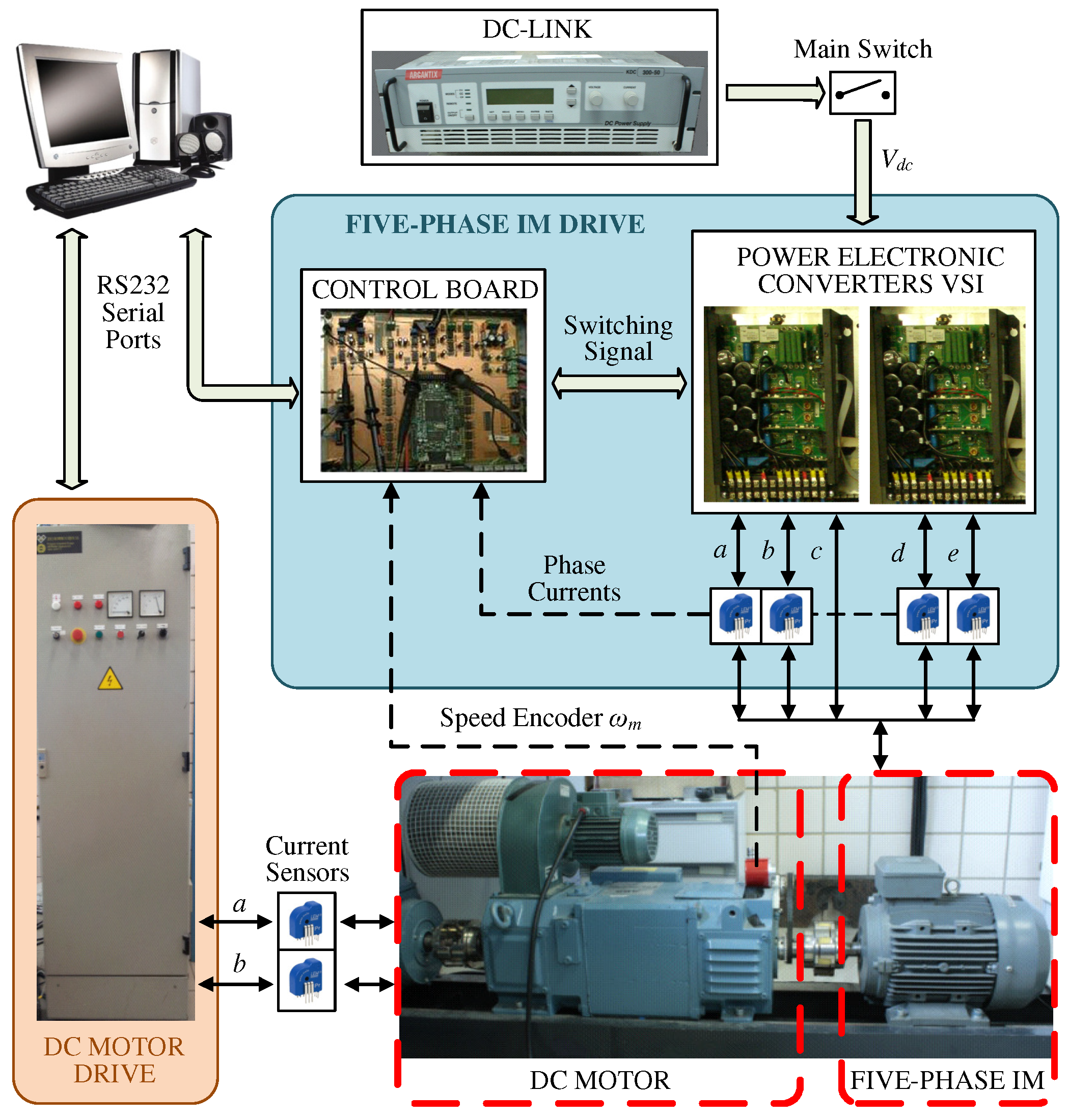
A current control performance analysis of the revised controllers is done using the experimental test bench shown in
Figure 2. The main component is a 30-slot symmetrical five-phase IM with distributed windings, whose electrical parameters are gathered in
Table 1. These have been obtained through the experimental tests described in [
22,
23]. Two three-phase two-level inverters from Semikron (SKS22F modules) supply the IM, and an external DC-link voltage of 300 V is connected to them. The multiphase system is controlled using a MSK28335 Technosoft board that includes a TMS320F28335 digital signal processor (DSP). The rotor mechanical speed (
) is measured using a GHM510296R/2500 digital encoder. Finally, an independently controlled DC machine is used to impose an external variable load torque in the shaft of the IM.
The controllers used in the comparison are the FCS-MPC technique with the conventional backtracking procedure (MPC-C1) and the open-loop observer (MPC-C2), the FCS-MPC method with a closed-loop rotor current observer (MPC-OB), and the VSTLPC. Equal cost functions are applied in MPC-C1, MPC-C2 and MPC-OB with a weighting factor of
, for the reasons presented in
Section 2. The Luenberger rotor current observer is designed using a fourth order Butterworth filter (
10), since the system presents two real poles that are maintained in the design of the observer:
A value of
s has been optimally selected by simulations in order to produce the lowest observation error in all speed range. Regarding the sampling time, it is imposed as
s for the three FCS-MPC techniques with fixed discretization. For the case of the VSTLPC method, the sampling time is limited by a minimum value of
s to make a fair comparison with the other controllers, and a maximum value of
s to avoid larger sampling periods that could deteriorate the control performance [
17]. The lead time is set to
s.
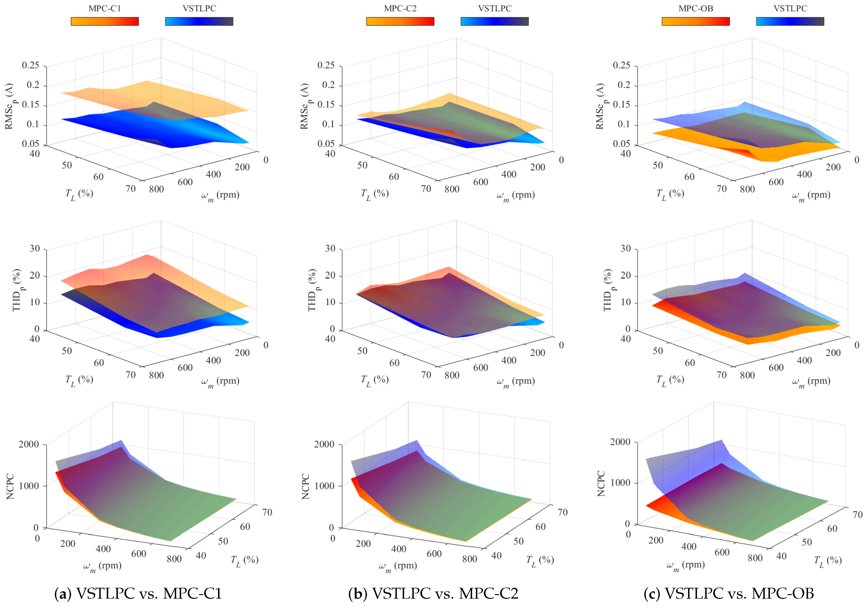
First, several steady-state tests have been carried out for each controller and the performance analysis is done on the basis of the mean square tracking error of the phase currents (RMSe
), the total harmonic distortion in the phase currents (THD
), and the number of commutations per cycle (NCPC) in the VSI legs. In all tests, the
d-current reference is fixed to
A to produce the rated flux and the system is closed-loop speed controlled using an outer PI regulator that provides the
q-current reference. In this way, it is possible to drive the machine to a constant rotor speed in the range of 50 rpm to 700 rpm. In addition, a variable load torque between the
to the
of the nominal torque is imposed. The obtained results are plotted in
Figure 3. In each column, the VSTLPC technique is compared with one of the other controllers in terms of the three aforementioned figures of merits. In such a way, the interest of including the non-fixed sampling against the FCS-MPC methods is revealed.
Regarding the current tracking performance and the harmonic content, lower values of RMSe
and THD
are observed in the VSTLPC technique in all considered operating conditions when it is compared with the MPC-C1 and MPC-C2 methods, being the difference bigger in the first comparison. However, the opposite occurs when the VSTLPC and MPC-OB techniques are compared. In this case, the RMSe
and the THD
values are lower for the MPC-OB, indicating that the inclusion of the rotor current observer in the FCS-MPC is enough to produce a significant improvement in the current control performance with respect to the conventional techniques. It must be noticed that the backtracking procedure based on the open-loop rotor current observer (MPC-C2) provides better results than the most conventional rotor estimation approach (MPC-C1), demonstrating a higher robustness to external disturbances as it was stated in
Section 2. In terms of the number of commutations per cycle, the VSTLPC produces the highest values, being this effect accentuated by the decrease of the speed, while the MPC-OB presents the lowest values in most cases.
It is interesting to mention that, in general, the evolution with the speed and the torque of all performance parameters is similar for all considered control techniques, regardless of the different values between them.
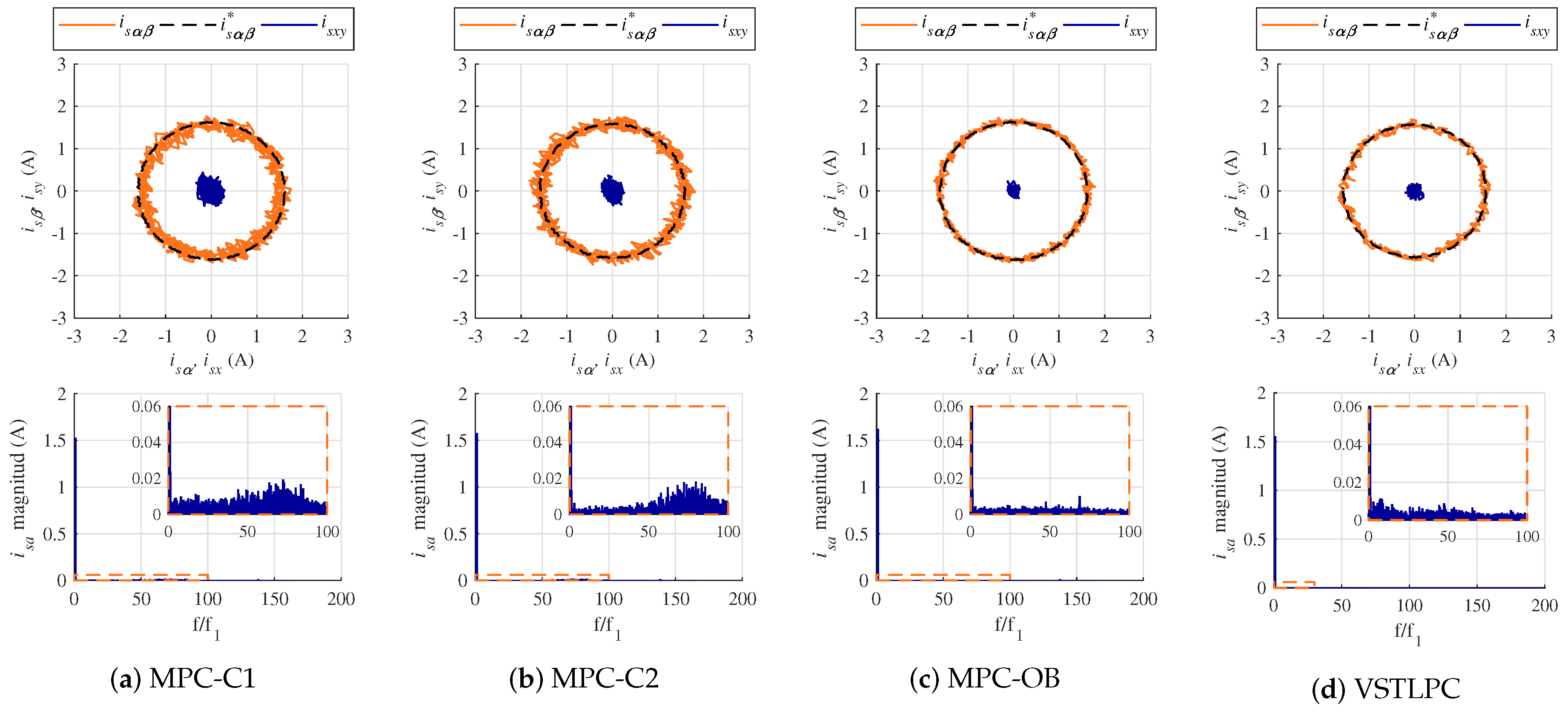
To complete the previous analysis,
Figure 4 and
Figure 5 show the current control performance of all considered controllers for two of the analyzed operating conditions: 100 rpm and
of the nominal torque (
Figure 4), and 600 rpm and
of the nominal torque (
Figure 5). For the first experiment, the circular
–
and
x–
y current trajectories and their references appear in the upper plots, while in the second test the evolution with the time of the
and
x currents are shown. In both tests, the spectrum of the
phase current is plotted and zoomed in the lower plots. These spectrums show harmonics and inter-harmonics that have been measured following the guidelines of the ICE standard [
24], but after adapting the normative to the case under study. Thus, nine and 10 cycles of the current signal have been used for the spectrum calculation in the 100 rpm and 600 rpm cases, respectively, in order to guarantee a good resolution.
It can be seen that the worst current tracking performance is obtained with the MPC-C1 technique, which presents a small offset in the tracking of the
–
currents. This offset is a characteristic of most predictive controllers [
3] but it is significantly reduced by the application of the closed-loop observer and the variable sampling. The harmonic and noise content is also reduced with the new controllers (MPC-OB and VSTLPC), as evidenced by the lower ripple in the
–
–
x–
y currents and the reduced magnitude in the current spectrum in comparison with conventional FCS-MPC techniques (MPC-C1 and MPC-C2). This, in turn, leads to a more efficient flux and torque production with lower copper losses. Focusing on the current spectrum, it is interesting to see that the MPC-C1 technique presents a more continuous spectrum with high magnitude of harmonics in a large frequency domain, while the MPC-C2 method shows significant harmonic distortion principally at high frequencies (this effect is more accentuated at lower speeds and loads). Conversely, the MPC-OB and VSTLPC approaches effectively reduce the harmonic magnitude in all the frequency domain. Although the VSTLPC presents some peaks of distortion at low frequencies for specific operating points, the total harmonic distortion is still lower than in conventional FCS-MPC methods (
Figure 3).
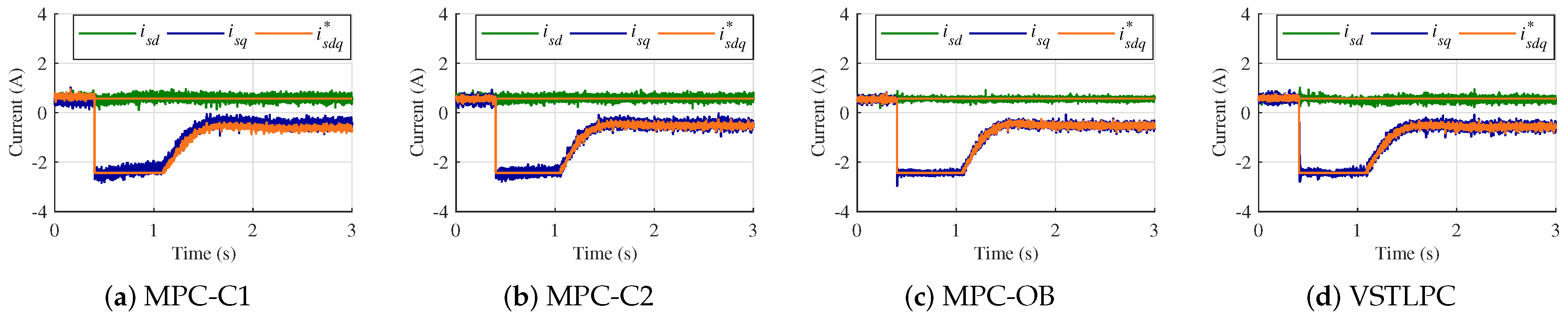
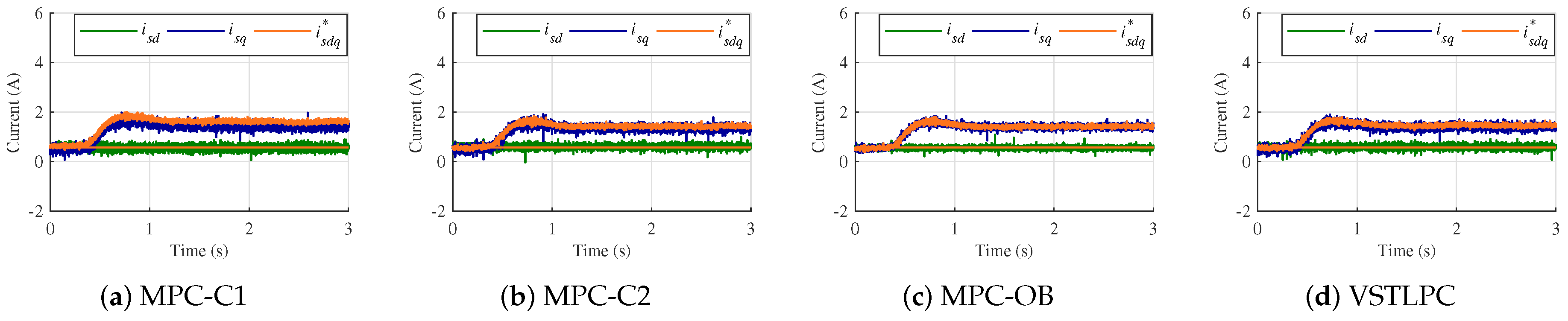
Three dynamic tests have also been done in order to validate the current control performance during the transient. The first one consists in a speed reversal test from
rpm to 500 rpm imposing a load torque equal to the 60% of the nominal one. The second test is a speed step from 0 rpm to 500 rpm imposing a load torque of the 60% too. Finally, the third test is a torque step from 0% to 60% of the nominal torque at 500 rpm. Since all controllers present similar speed response in each test, only the speed evolution for the case of the VSTLPC method is presented in
Figure 6 for simplicity reasons. Diversely, the
d–
q currents evolution with time for each controller is presented in
Figure 7,
Figure 8 and
Figure 9 for the speed reversal, the speed step and the torque step experiments, respectively. Regarding the transient performance, it can be stated that it is quite similar for all controllers. This fact demonstrates that the inclusion of the closed-loop rotor current observer and the variable sampling time does not deteriorate the fast transient performance that characterizes the predictive controller. Furthermore, superior current tracking and lower harmonic distortion are provided by the MPC-OB and VSTLPC techniques, as it was expected by the previous steady-state results. This is evidenced by the
currents performance in
Figure 7,
Figure 8 and
Figure 9, where the current ripple and the previously cited offset are higher when using the conventional MPC-C1 and MPC-C2 methods even during the transient. Consequently, the harmonic content is also higher in that cases comparing to the recently proposed current control approaches.
To conclude the comparative assessment, the computational cost of analyzed controllers was studied. The conventional MPC-C1 and MPC-C2 approaches require, in the DSP-based experimental system, a computational cost around
s and
s, respectively. On the other hand, the MPC-OB and the VSTLPC techniques require
s and
s, respectively. This increment is completely affordable taking into account that the minimum sampling time is
s. It must be noticed that the computational burden of the VSTLPC strongly depends on the operating point, as it was stated in [
17], being the previously indicated computational cost a mean value.
To summarize, the VSTLPC and MPC-OB techniques outperform the conventional FCS-MPC methods in terms of harmonic content and tracking performance, but the closed-loop observer provides the best results in all the operating range. Regarding the NCPC, the VSTLPC provides the highest values while the lowest values are produced, in the most cases, by the MPC-OB. Note that the obtained benefits do not excessively increase the computational cost of the controller and do not compromise the fast transient response of the regulated system.


