Abstract
In this study, a dual-output converter with a wide input voltage range is proposed for directly equalized charging of series-connected batteries without additional power conversion losses. Compared with most of the equalized charging topologies, such as the those with a multi-winding transformer or voltage multiplier, the proposed converter could be applied to different voltage conversion ratio applications. The proposed converter is capable not only of step-down but also step-up/down power conversions for different input voltage levels. By operating in discontinuous conduction mode, the diode reverse recovery losses can be eliminated and operation stability can also be enhanced. The operation principles and design criteria are both illustrated. A prototype of charging two series-connected LiFePO4 batteries is constructed. Corresponding experimental results of different input voltage levels are provided to verify the performance and validity.
1. Introduction
In recent years, due to environmental issues and fuel crisis, renewable energy has attracted much attention, and electric vehicles are becoming more and more popular. The battery power module is one of the most important components in electric vehicles [1]. In these battery power modules, several battery cells are always connected in series to achieve higher output voltage. However, the state of charge (SoC) and the voltage of each battery cell in the module could be unbalanced during charging or discharging because of differences in cell manufacturing, materials, packaging, etc. Moreover, improper charging process would cause overcharging or over-discharging damage to the battery cells in the module and shorten its lifetime [2,3].
Several equalized chargers were proposed for preventing the battery cells from overcharging [4,5,6,7,8,9,10,11,12,13,14,15,16,17,18,19,20]. These topologies can basically be divided into two types. One is the two-stage topology composed of a bulk charger and a cell equalization circuit. The bulk charger is used to directly provide the charging power to the series-connected batteries. The unbalanced charge between each battery can be eliminated by the second-stage circuit, i.e., the cell equalization circuit [4,5,6,7,8,9,10,11,12,13,14,15]. However, the twice power conversion process from the input power source to each battery would cause additional power losses. The other topology is the multi-output converter one [16,17,18,19,20,21]. Compared with two-stage equalized chargers, multi-output converters can directly provide charging power to each battery individually and ensure the charge equalization. The batteries can then be equally charged without twice power conversion process. Multi-winding transformers and voltage multipliers are utilized to develop the multi-output converters for equalized charging the series-connected batteries [16,17,18,19]. The multi-winding transformer has been widely used for isolated power transmission between more than two ports. However, not only the hardware volume but also the implementation difficulty would be increased. Furthermore, the mismatch in the windings may result in undesired output voltage variation between each output port. For example, the effective turn ratio and the coupling coefficient between the windings may not be identical in the multi-winding transformer. As a result, the induced voltages in the secondary windings will also not be the same. As for the other charger topology with a voltage multiplier, the dynamic response is always the major problem [20,21]. Most of these topologies are designed only for either step-down or step-up/down operations.
The most popular charging strategy for Li-ion batteries is the so-called constant-current/constant-voltage (CC/CV) charging [22]. To enhance the charging efficiency, several extended charging strategies are proposed. The pulse charging strategy is proposed to provide a rest time interval for improving the charging efficiency. However, the periodic pulse charging current seems to be harmful to Li-ion batteries [23]. Other extended charging strategies, such as fuzzy control, neural network, sinusoidal ripple current charging, etc., are proposed and intended to improve the charging performance [24,25,26]. However, these extended charging strategies usually require complicated computing algorithms or accurate equivalent models of the Li-ion battery which would increase the complexity and difficulty of implementation.
A dual-output converter is proposed for equalized charging two series-connected batteries in low power applications such as the battery module of light electrical scooters. The proposed converter provides a wide voltage-ratio and can be operated in either step-down or step-up/down operation mode, depending on the input voltage level. A dual-loop controller is also proposed for controlling the individual charging current supplied to each battery. The three major contributions of this study can be described as follows: First, the input voltage range is wide because the proposed converter can be operated in step-down or step-up/down mode. Second, compared with the charge equalization circuits, the charging power is directly delivered to each battery without additional power losses from secondary power conversion. Third, the proposed converter is inherently stable and easy to control. The converter operated in DCM would essentially exhibit simple single-pole transfer functions because the second pole and right-half-plane (RHP) zero (in the step-up/down mode) would be pushed to higher frequencies [27,28,29,30]. The single-pole dynamic response would make the design of the controller easier. In the following sections, the steady-state operation principles are analyzed and design criteria of the inductor for DCM operation are also derived. A control strategy based on the analysis results is proposed. The widely-used CC/CV charging strategy is also adopted for easy implementation and battery lifetime consideration. Corresponding experiments are carried out to verify the analysis and performance of the proposed converter.
2. Circuit Configuration and Operation Principles
The configuration of the proposed dual-output converter is shown in Figure 1. The central part of the proposed converter is composed of an active switch Q1, a diode D1, and an inductor L. The two series-connected batteries B1 and B2 are connected to the output terminal. Furthermore, an equalization circuit composed of two active switches Q2 and Q3 and two diodes D2 and D3 is integrated into the converter. By adjusting the duty ratios d2 and d3, the corresponding battery charging currents can then be controlled for equalized charging. The operation principles of the equalization circuit are similar to the three-level DC converters [31]. Diodes D2 and D3 are used to prevent battery short-circuit when switches Q2 or Q3 are turned on.
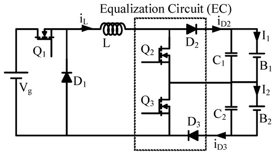
Figure 1.
Circuit configuration of the proposed converter.
To simplify the analysis of the proposed converter, all components are assumed to be ideal and the converter is operated in DCM. The operation principles of step-down and step-up/down operation modes are illustrated respectively.
Firstly the converter operation in the step-down mode for high input voltage applications is analyzed and illustrated. Figure 2a shows the waveforms of charging only one battery when the other battery is fully charged. Switch Q2 is always turned on to bypass the charging current and switch Q3 is always turned off for charging battery B2. Figure 2b shows the waveforms of charging two batteries with the same current simultaneously. Both switches Q2 and Q3 are always turned off for charging batteries B1 and B2. It can be seen that the operation principles of the converter in these two conditions are similar to the Buck converter. However, if the required charging currents for two batteries are different, only one of switches Q2 and Q3 will be activated. The waveforms and equivalent circuits in this condition are shown in Figure 3 and Figure 4.
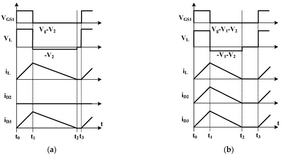
Figure 2.
Step-down operation relative waveforms of (a) single-battery charging, (b) dual-battery charging with the same current.
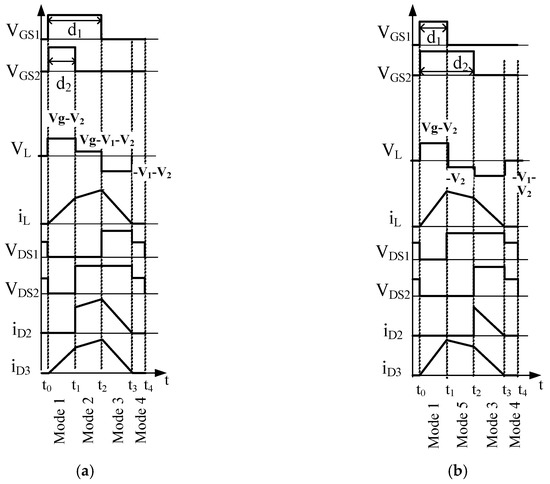
Figure 3.
Waveforms of proposed converter for lower charging current to battery B1 at (a) d2 < d1, (b) d2 > d1.
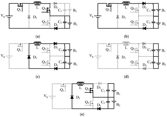
Figure 4.
Equivalent circuits of step-down operation. (a) mode 1, (b) mode 2, (c) mode 3, (d) mode 4, (e) mode 5.
In Figure 3, the required charging current for battery B1 is less than that for battery B2. Hence, switch Q3 is always turned off to keep battery B2 being charged with inductor current iL directly. To reduce the charging current to battery B1, switch Q2 would be activated to partially bypass the inductor current. The inductor current is mainly controlled by adjusting the duty ratio of switch Q1. There are two possible sequences of operation modes depending on the relationship between duty ratios of switches Q1 and Q2, namely d1 and d2. The corresponding waveforms while d1 > d2 are shown in Figure 3a. the sequence of operation modes is Mode1-Mode2-Mode3-Mode4 and the corresponding equivalent circuits are shown in Figure 4a–d. Figure 3b shows the waveforms of the sequence while d1 < d2. The sequence of operation mode is Mode1-Mode5-Mode3-Mode4. The equivalent circuit of the operation Mode 5 is shown in Figure 4e.
- Mode 1:
- In this mode, switches Q1 and Q2 are turned on. The equivalent circuit is shown in Figure 4a. Diodes D1 and D2 are reverse-biased and diode D3 is forward-biased. Battery B1 is bypassed to reduce equivalent charging current. The inductor voltage is (Vg − V2) and the inductor current iL is increased. Only battery B2 is charged by inductor current in this mode. This mode is ended while either switch Q1 or Q2 is turned off.
- Mode 2:
- Only switch Q1 is turned on in this mode as shown in Figure 4b. Diodes D2 and D3 are forward-biased and diode D1 is reverse-biased. The two batteries, B1 and B2, and the inductor are charged by the input source simultaneously. The inductor current is increased with lower slope (Vg − V1 − V2)/L.
- Mode 3:
- While all switches are turned off, diodes D1–D3 are all forward-biased as shown in Figure 4c. The energy pre-stored in the inductor is released to batteries, B1 and B2 through three diodes D1–D3. The voltage on the inductor is negative and equal to (−V1 − V2) and the inductor current is then decreased.
- Mode 4:
- When the inductor current iL is decreased to zero, the operation mode is changed into mode 4 and the equivalent circuit is shown in Figure 4d. Therefore, there is no diode reverse recovery loss.
- Mode 5:
- Only switch Q2 is turned on in this mode, as shown in Figure 4e. Diodes D1 and D2 are forward-biased and diode D2 is reverse-biased. The inductor current is decreased with slope (−V2/L) and only battery B2 is charged.
To ensure that the proposed converter is always operated in DCM even when only one battery left is charged, i.e., duty ratio d2 = 1, the inductor should be properly designed. The criterion is the averaged inductor current should be lower than that in the boundary condition. In the boundary condition, the peak value ILpk and averaged value ILB of the inductor current can be expressed as:
where is the diode forward voltage. As a result, the design criterion of the inductor can be derived as follows:
where is the minimum battery charging voltage.
In the low input voltage case, the input voltage might be lower than the whole battery pack voltage but higher than the single battery voltage. Therefore, the converter should be able to perform step-up/down power conversion between the input source and the batteries. By changing the control signals of switches Q2 and Q3, the proposed converter is then able to perform step-up/down operation. Figure 5a shows the waveforms of charging only one battery B2. Switch Q2 is always turned on to bypass the charging current. For charging two batteries simultaneously with the same current, all three switches are turned on and off at the same time and the relative waveforms are shown in Figure 5b. From these two figures, it can be seen that the inductor is charged first by the input source while the switches are turned on and then the charged energy is released to the batteries when the switches are turned off.
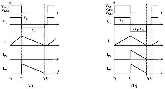
Figure 5.
Step-up/down operation relative waveforms of (a) single-battery charging, (b) dual-battery charging with the same current.
If the required charging currents of two batteries are different, the turned-on time of the corresponding switch will be extended to reduce the respective charging current. Figure 6 shows the waveforms for charging two batteries and the required charging current for battery B1 is lower. Figure 7 shows the equivalent circuits of the corresponding intervals in Figure 6.
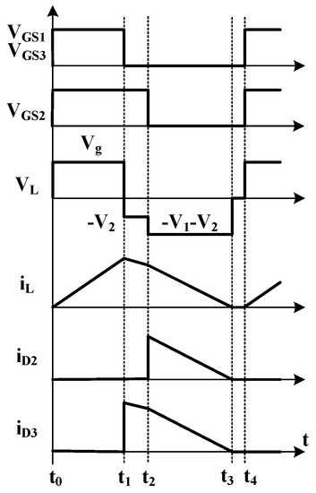
Figure 6.
Waveforms of charging two batteries with different currents in step-up/down operation.
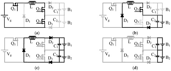
Figure 7.
Equivalent circuits of step-up/down operation. (a)t0 ~ t1, (b) t1 ~ t2, (c) t2 ~ t3, (d) t3 ~ t4.
The averaged inductor current in step-up/down operation mode should also be always lower than that in the boundary condition for proper DCM operation. In the boundary condition for charging only one battery with step-up/down mode, the peak value ILpk and averaged value ILB of the inductor current can be expressed as:
As a result, the design criterion of the inductor for step-up/down operation mode can be derived as follows:
3. Battery Charging Profile and Control Strategy
The common CC/CV charging method is used to charge each battery in this study. Voltages and currents of each battery and inductor current are all fed back for charging control. With the assumption of lower SoC in battery B2, two possible charging profiles of the series-connected batteries are shown in Figure 8. Figure 8a shows the charging profile for a small SoC difference between two batteries. In the first region, two batteries are both charged with the constant current, i.e., the dual constant-current (DCC) region. Batteries B1 and B2 are charged with the inductor current in series. Then, battery B1 would firstly be charged into the constant-voltage mode and battery B2 is still charged with the constant current. The second region is the hybrid constant-current constant-voltage (HCCCV) region. Battery B2 is charged into the constant-voltage mode and battery B1 is still in the constant-voltage mode. The converter is operated into the third region, i.e., the dual constant-voltage (DCV) region. In the next region, the charging process of battery B1 is already finished and battery B2 remains to charge in the constant-voltage mode. This region is the single constant-voltage (SCV) region. The whole charging profile of the two series-connected batteries is ended when both batteries B1 and B2 are fully charged.
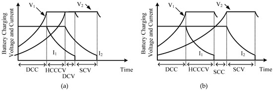
Figure 8.
Two possible charging profiles for the proposed converter with (a) small difference of SoC, (b) large difference of SoC.
The other charging profile of large SoC difference is shown in Figure 8b. The major difference between the two charging profiles in Figure 8 is the third charging region. In Figure 8b, battery B2 is still charged with the constant current when the charging process of battery B1 is already finished. Therefore, there is only one battery charged with the constant current. The third region in Figure 8b is the single constant-current (SCC) region.
Under the assumption of lower SoC in battery B1, duty ratio d3 is always zero and output current I1 should be controlled to be lower than current I2 by increasing duty ratio d2 in HCCCV, DCV, SCC, and SCV regions as shown in Figure 8. As for the DCC region, duty ratio d2 is set to zero and two batteries are then charged with the same output current, i.e., I1 = I2 = IL = ICC*.
To achieve the charging strategy described above, a closed-loop controller is developed for adjusting the duty ratios. Voltage and current of each battery are all fed back. Low pass filters are integrated to filter out the undesired high-frequency ripple components. The block diagram of the charging controller is shown in Figure 9. Charging current command for each battery, i.e., I1* and I2*, is determined by the voltage control. The constant-voltage command VCV*, i.e., the maximum battery charging voltage, is the reference value of battery voltage feedback control. When the battery voltage is much lower than the command VCV*, the determined charging current would be limited to the constant-current command ICC*, i.e., the maximum battery charging current. The duty ratios of switches Q2 and Q3, i.e., d1 and d2, are then determined by the current control of corresponding battery current. The inductor current is also fed back for adjusting the duty ratio of switch Q1. The inductor current command IL* is determined by the conditions of battery charging current commands I1* and I2*. Table 1 shows the criteria of the inductor current command determination where Ig* represents the input current command expressed as:
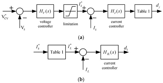
Figure 9.
Block diagram of the equalized charging controller, where k = 1,2 and j = 2,3, (a) the dual-loop controllers of charging two batteries, (b) the inductor current controller.

Table 1.
Inductor current command determination criteria.
When the current commands of batteries B1 and B2 are identical, switches Q2 and Q3 would be both turned off in step-down mode or be both synchronized with switch Q1 in step-up/down mode. Once the current command of battery B1 is larger, switch Q3 would be activated to reduce the charging current to battery B2, and switch Q2 would be turned off in step-down mode or be synchronized with switch Q1 in step-up/down mode, respectively. On the contrary, switch Q2 would then be activated to reduce the charging current for battery B1 when the current command of battery B1 is lower.
In the past decades, several state averaged models for DCM PWM converters have been proposed [27,28,29,30]. These models can basically be divided into two types, namely the reduced-order models [27,28,30] and full-order models [29,30]. The dynamic of the inductor current in the DCM converter would disappear because of the state averaging procedure in one switching cycle. Therefore, the averaged model becomes a reduced-order model with the remaining dynamic of output capacitor voltage. The dynamic of the converter would become a simple single-pole system. Compared with the full-order models, the reduced-order models can provide good accuracy in low frequency, below about 1/10 switching frequency, as shown in [29]. Although the accuracy of the reduced-order model is limited, the reduced-order model is simpler for designing the controller and should be accurate enough for the battery charging applications with CC/CV charging strategy. The dynamics of the required charging current and voltage commands are relatively slow. Therefore, the reduced-order model is adopted to realize the dynamic of the proposed converter and design of the controller parameters.
For simplifying the dynamic response analysis, all components are assumed to be ideal and the step-down operation with d3 = 0 is taken as an example. The derived state averaged equations according to the waveforms shown in Figure 3a are expressed as follows:
The dynamics of the inductor current disappear because of the state averaged modeling procedure [27,30]. In the two output voltage state equations, the capacitors Ce1 and Ce2 are used to represent the effective total capacitance of the output capacitors and the battery. The equivalent capacitance of the LiFePO4 battery is quite large and might up to thousands of Farad [32]. From the current waveforms shown in Figure 3a, the averaged currents in one switching cycle are shown as follows:
where , , and . Let the averaged state variable to be the combination of a DC and a small signal component, i.e., , and ignore high order items for linear approximation. Then, the corresponding small signal model can be expressed as follows:
According to Equations (16)–(19), the dual-loop controller of each battery as shown in Figure 9 can then be further illustrated in Figure 10. The currents and voltages are feedback with second-order low pass filters (LPFs). The corner frequency of the filters is designed to 2 kHz. The current loop proportional-integral controller is set with KPc = 0.1 and KIc = 100. In the voltage loop, the parameters are set to KPv = 2 and KIv = 0.02. The current loop gain is KdiGPIcGLP and the corresponding bode plot is shown in Figure 11. Then, the voltage loop gain becomes GPIvGLP[KdiGPIc/(1 + Kdi GPIcGLP)] and the corresponding bode plot is shown in Figure 12. From the bode plots, it can be seen that the gain margin and phase margin are enough for stabilizing the system. The bandwidth of the voltage control loop is very low because of the large equivalent capacitance of the battery.
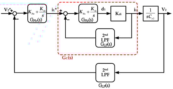
Figure 10.
Schematic diagram of the dual-loop controller.
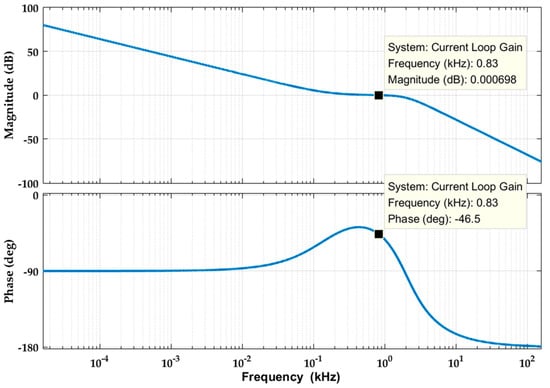
Figure 11.
Bode plot of the current control loop gain.
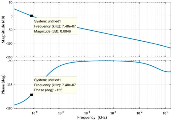
Figure 12.
Bode plot of the voltage control loop gain.
4. Experimental Results
The test setup of the constructed prototype is shown in Figure 13. To ensure the measuring precision, a WT330 precision power analyzer (Yokogawa, Tokyo, Japan) is used for accurate efficiency measurement of the proposed converter. The efficiency is calculated with the voltamperometric method. The relative voltage and current waveforms are measured by a 24Xs-A digital oscilloscope (Lecroy, Chestnut Ridge, NY, USA).
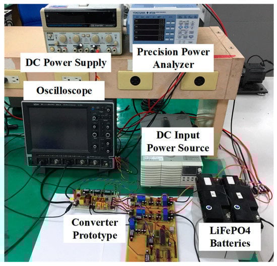
Figure 13.
The test setup of the proposed converter.
Figure 14 shows the schematic diagram of the controller. A microcontroller dsPIC30F4011 is used to implement the control strategy shown in the previous section digitally. Currents iL, i1 and i2 and voltages V1 and V2 are transduced to analog signals with three current transducers and two voltage transducers, respectively. A 2nd order LPF is used to filter out the high-frequency ripple components. Then, all current and voltage feedback signals are converted into digital data via the analog to digital converter (ADC) module. The corresponding PWM signals for the three active switches are then generated via the output compare (OC) module. The PWM signals would then be delivered to the MOSFET driver circuit for providing the driving voltages VGS1–VGS3 to the three switches.
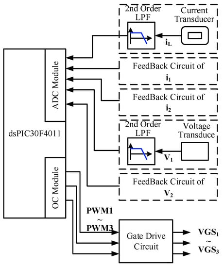
Figure 14.
Schematic diagram of the controller.
The experiment parameters are listed in Table 2. Batteries B1 and B2 are pre-charged to around 90% SoC in corresponding experiments for shortening the testing time. To verify the operation and performance of the proposed converter, two charging experiments of the two batteries with unequal SoC are carried out. In the first charging experiment setting, the SoC of battery B1 is pre-charged to be about 0.18 Ah higher than that of battery B2. In the second experiment setting, the pre-charged SoC of battery B1 is only about 0.04 Ah higher than that of battery B2.
Table 2.
Circuit parameters of the constructed prototype.
The charging experimental results with large SoC difference are shown in Figure 15. The measured charging voltages and currents are shown in Figure 15a. The two batteries are firstly charged in DCC region. When the voltage of battery B1 is increased to the rated charging voltage, switch Q2 will be activated to reduce the charging current I1 for constant voltage charging and the converter is operated in HCCCV region. Once the charging process of battery B1 is finished and battery B2 is still charged in CC mode, the converter is operated in SCC region. Then, the last region is the SCV region for charging battery B2 in the CV mode. The increased charges of the two batteries are shown in Figure 15b. It can be seen that the amount of increased charge to battery B2 is about 0.18 Ah more than that of battery B1.
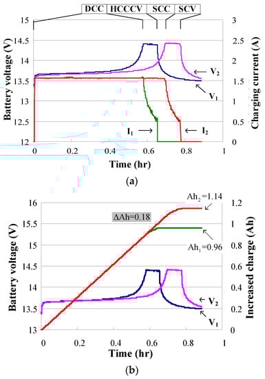
Figure 15.
Measured data of charging two battery with large SoC difference. (a) the measured charging voltages and currents; (b) the increased charges of the two batteries.
Figure 16 shows the results of charging experiment of two batteries with small SoC difference. In the measured waveforms of voltages and currents shown in Figure 16a, the third charging region is the DCV region. In this region, the voltage of battery B2 is increased to the rated charging voltage before the charging process of battery B1 is finished. From the measured data of increased charge shown in Figure 16b, it can be seen that the charge difference is only about 0.04 Ah.
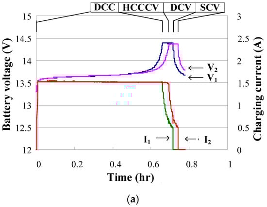
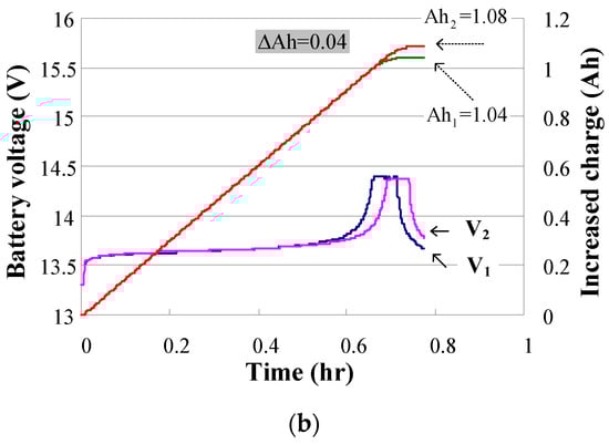
Figure 16.
Measured data of charging two battery with small SoC difference. (a) the measured waveforms of voltages and currents; (b) the measured data of increased.
The waveforms of the converter operated at 120 V input voltage condition, i.e., the step-down operation mode, are shown in Figure 17. Figure 17a shows the waveforms of the DCC region with 25 V battery pack voltage and 1.5 A charging current. Figure 17b shows the waveforms of the SCC region with 13 V single battery voltage and 1.5 A charging current. In the DCC and SCC regions, only switch Q1 is activated to control the charging current. Figure 17c shows the waveforms of the HCCCV region with battery voltages, V1 = 14.4 V and V2 = 12.3 V, and charging currents, I1= 1 A and I2= 1.5 A. In this region, switch Q2 is activated to reduce the charging current for battery B1.
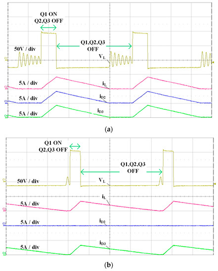
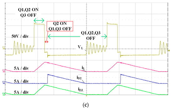
Figure 17.
Measured waveforms of step-down mode in (a) DCC, (b) SCC and (c) HCCCV regions.
The waveforms of the converter operated at 24 V input voltage condition, i.e., the step-up/down operation mode, are shown in Figure 18. Figure 18a shows the waveforms of the DCC region with 26 V battery pack voltage and 1.5 A charging current. Figure 18b shows the waveforms of the SCC region with 13 V single battery voltage and 1.5 A charging current. In DCC and SCC regions of the step-up/down operation, switches Q1 and Q2 are activated by the same PWM signal to control the charging current. Figure 18c shows the waveforms of the HCCCV region with battery voltages, V1 = 14.4 V and V2 = 12.5 V, and charging currents, I1 = 1 A and I2 = 1.5 A. In this region, the duty ratio of switch Q2 is increased to reduce the corresponding charging current. From the measured waveforms of step-down and step-up/down operations, it can be seen that the peak current is larger in step-up/down operation for the same averaged output current. The larger peak current would result in additional switching power losses.
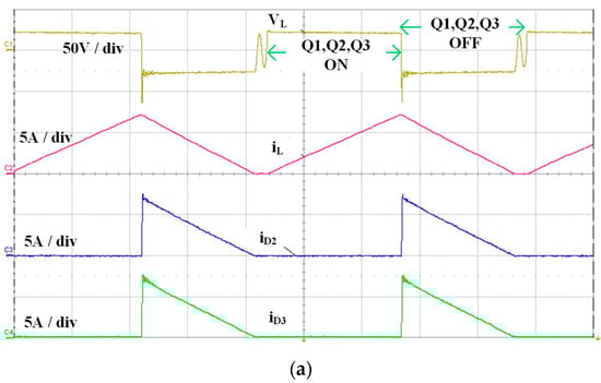
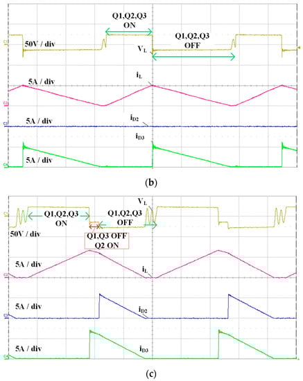
Figure 18.
Measured waveforms of step-up/down mode in (a) DCC, (b) SCC and (c) HCCCV regions.
From the measured diode currents iD1 and iD2, it can be seen that there are significant current ripple components. To prevent the batteries from damage by the high-frequency current ripple components, three kinds of capacitors are connected to the output terminals of the proposed converter. Figure 19 shows the output voltage ripple and output current with different kinds of capacitors at 1.5 A averaged output current. The output voltage ripple is measured with AC coupling function of the oscilloscope. The output current ripple can be greatly reduced by adding suitable capacitors.
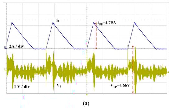
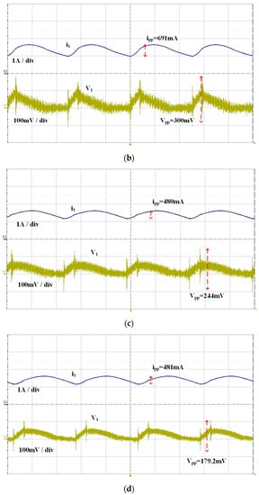
Figure 19.
Output voltage and current ripple with (a) no capacitor, (b) an electrolytic capacitor, (c) an electrolytic and an aluminum solid capacitors and (d) an electrolytic, an aluminum solid and a MLCC capacitors.
The total effective ESR at the output terminal can be reduced by adding an aluminum solid capacitor. The MLCC is used to attenuate the high-frequency noise. From the measured waveforms in Figure 19d, it can be seen that the peak to peak current is greatly reduced to 480 mA. Compared with the measured waveforms without additional capacitors shown in Figure 19a, the current ripple is greatly reduced to only about 10%.
The efficiencies of the proposed converter operated in DCC, SCC, DCV, and SCV regions are measured and shown in Figure 20, respectively. In DCC and SCC regions measurement, the battery charging current is controlled to the rated charging current, i.e., 1.5 A. The charging voltage of DCC region is within the range of 21 V to 28.8 V and that of SCC region is within the range of 10.5 V to 14.4 V. In DCV and SCV regions measurement, the charging voltage is controlled to 28.8 V and 14.4 V, respectively. The charging current is within the range of 0.5 A to 1.5 A. The efficiency of the proposed converter in step-down operation is about 89% to 91% in charging two batteries and about 84% to 88% in charging only one battery. The efficiency of the proposed converter at step-up/down mode is about 86% to 88%. The lower efficiency in step-up/down operation results from the higher switching power losses from the higher peak current.
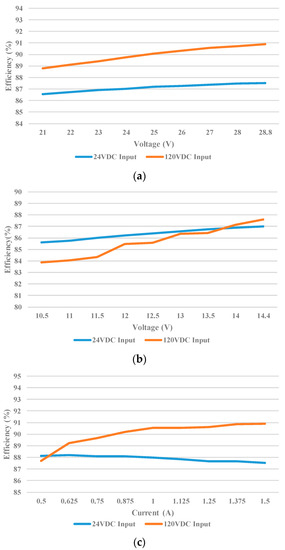
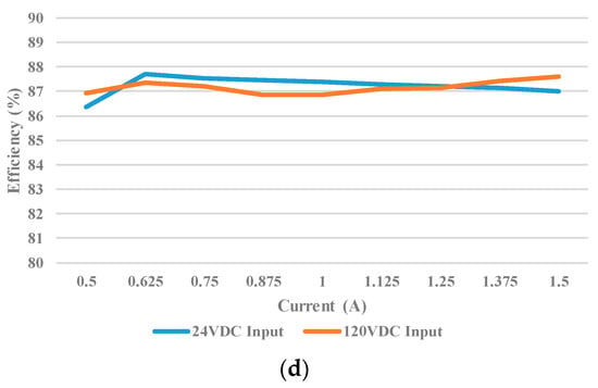
Figure 20.
Measured efficiency in (a) DCC, (b) SCC, (c) DCV and (d) SCV regions.
5. Discussion and Conclusions
A dual-output converter is proposed for equalized charging two series-connected batteries. The proposed converter is also able to perform step-down and step-up/down operations. Corresponding operation principles and design criteria are both illustrated. According to the input voltage level, the proposed converter could be designed to perform either step-down or step-up/down operation for equalized charging. A charging controller based on the CC/CV charging method is also provided. The equalized charging performance is verified by the experimental results. The efficiency of the proposed converter operated in step-down mode with 120 V input voltage is about 91% and 88% in step-up/down mode with 24 V input voltage.
The higher peak current in step-up/down operation results in additional switching power losses. Therefore, to partially enhance the efficiency, the converter might be changed into the step-down operation while only a single battery charging is required. The efficiency might be further improved by reducing the switching power losses with the zero-current-switching technique in future work.
The proposed dual-output converter is only suitable for low power applications with two series-connected batteries, such as light electrical scooters. For applying to high power electric vehicles with more series-connected batteries, the proposed converter might be further integrated with coupling inductors to extend the number of output terminals. Furthermore, the components in the practical circuit might be faulty because of manufacturing tolerance. A great multiscale filtering algorithm is proposed to enhance stability when some nodes or modules in the network/system are faulty [33]. In the future, the effect of faulty components can be further analyzed and corresponding coordination control strategy might then be developed to ensure stability and performance of the proposed converter.
Funding
This work was founded by the Ministry of Science and Technology, Taiwan, under Grant No. MOST 107-2622-E-018-005-CC3.
Conflicts of Interest
The author declares no conflict of interest.
References
- Khaligh, A.; Li, Z. Battery, ultracapacitor, fuel cell, and hybrid energy storage systems for electric, hybrid electric, fuel cell, and plug-in hybrid electric vehicles state of the art. IEEE Trans. Veh. Technol. 2010, 59, 2806–2814. [Google Scholar] [CrossRef]
- Hung, S.T.; Hopkins, D.C.; Mosling, C.R. Extension of battery life via charge equalization control. IEEE Trans. Ind. Electron. 1993, 40, 96–104. [Google Scholar] [CrossRef]
- Nelson, J.P.; Bolin, W.D. Basics and advances in battery systems. IEEE Trans. Ind. Appl. 1995, 31, 419–428. [Google Scholar] [CrossRef]
- Moo, C.S.; Hsieh, Y.C.; Tsai, I.S. Charge equalization for series connected batteries. IEEE Trans. Aerosp. Electron. Syst. 2003, 39, 704–710. [Google Scholar] [CrossRef]
- Park, H.S.; Kim, C.E.; Moon, G.W.; Lee, J.H.; Oh, J.K. Two stage cell balancing scheme for hybrid electric vehicle Lithium-ion battery strings. In Proceedings of the 2007 IEEE Power Electronics Specialists Conference, Orlando, FL, USA, 17–21 June 2007; pp. 273–279. [Google Scholar]
- Lee, Y.S.; Cheng, M.W. Intelligent control battery equalization for series connected lithium-ion battery strings. IEEE Trans. Ind. Electron. 2005, 52, 1297–1307. [Google Scholar] [CrossRef]
- Lee, Y.S.; Cheng, M.W. Quasi-resonant zero-current-switching bidirectional converter for battery equalization applications. IEEE Trans. Power Electron. 2006, 21, 1213–1224. [Google Scholar] [CrossRef]
- Pascual, C.; Krein, P.T. Switched capacitor system for automatic series battery equalization. In Proceedings of the APEC 97, Atlanta, GA, USA, 27 February 1997; pp. 848–854. [Google Scholar]
- Baughman, A.C.; Ferdowsi, M. Double-tiered switched-capacitor battery charge equalization technique. IEEE Trans. Ind. Electron. 2008, 55, 2277–2285. [Google Scholar] [CrossRef]
- Park, H.S.; Kim, C.E.; Kim, C.H.; Moon, G.W.; Lee, J.H. A Modularized charge equalizer for an HEV lithium-ion battery string. IEEE Trans. Ind. Electron. 2009, 56, 1464–1476. [Google Scholar] [CrossRef]
- Park, H.S.; Kim, C.H.; Park, K.B.; Moon, G.W.; Lee, J.H. Design of a charge equalizer based on battery modularization. IEEE Trans. Veh. Tech. 2009, 58, 3216–3223. [Google Scholar] [CrossRef]
- Park, S.H.; Park, K.B.; Kim, H.S.; Moon, G.W.; Youn, M.J. Single-magnetic cell-to-cell charge equalization converter with reduced number of transformer windings. IEEE Trans. Power Electron. 2012, 27, 2900–2911. [Google Scholar] [CrossRef]
- Kim, C.H.; Kim, M.Y.; Park, H.S.; Moon, G.W. A modularized two-stage charge equalizer with cell selection switches for series-connected lithium-ion battery string in an HEV. IEEE Trans. Power Electron. 2012, 27, 3764–3774. [Google Scholar] [CrossRef]
- Daowd, M.; Antoine, M.; Omar, N.; Bossche, P.V.; Mierlo, J.V. Single Switched Capacitor Battery Balancing System Enhancements. Energies 2013, 6, 2149–2174. [Google Scholar] [CrossRef]
- Lv, J.; Song, W.; Lin, S.; Feng, Z.; Ding, Y. Investigation on dynamic equalisation performance of lithium battery pack management. IET Circ. Devices Syst. 2017, 11, 388–394. [Google Scholar] [CrossRef]
- Kutkut, N.H.; Wiegman, H.L.N.; Divan, D.M.; Novotny, D.W. Design considerations for charge equalization of an electric vehicle battery system. IEEE Trans. Ind. Appl. 1999, 35, 28–35. [Google Scholar] [CrossRef]
- Tang, M.; Stuart, T. Selective buck-boost equalizer for series battery packs. IEEE Trans. Aerosp. Electron. Syst. 2000, 36, 201–211. [Google Scholar] [CrossRef]
- Hsieh, Y.H.; Liang, T.J.; Chen, S.M.; Horng, W.Y.; Chung, Y.Y. A novel high-efficiency compact-size low-cost balancing method for series-connected battery applications. IEEE Trans. Power Electron. 2013, 28, 5927–5939. [Google Scholar] [CrossRef]
- Lambert, S.M.; Pickert, V.; Atkinson, D.J.; Zhan, H. Transformer-Based Equalization Circuit Applied to n-Number of High Capacitance Cells. IEEE Trans. Power Electron. 2016, 31, 1334–1343. [Google Scholar] [CrossRef]
- Uno, M.; Tanaka, K. Single-switch multioutput charger using voltage multiplier for series-connected lithium-ion battery/supercapacitor equalization. IEEE Trans. Ind. Electron. 2013, 60, 3227–3239. [Google Scholar] [CrossRef]
- Liu, J.; Xu, M.; Zeng, J.; Wu, J. Modified voltage equaliser based on Cockcroft–Walton voltage multipliers for series-connected supercapacitors. IET Electr. Syst. Transp. 2018, 8, 44–51. [Google Scholar] [CrossRef]
- Chen, B.Y.; Lai, Y.S. New digital-controlled technique for battery charger with constant current and voltage control without current feedback. IEEE Trans. Ind. Electron. 2012, 59, 1545–1553. [Google Scholar] [CrossRef]
- Savoye, F.; Venet, P.; Millet, M.; Groot, J. Impact of periodic current pulses on Li-ion battery performance. IEEE Trans. Ind. Electron. 2012, 59, 3481–3488. [Google Scholar] [CrossRef]
- Hsieh, G.C.; Chen, L.R.; Huang, K.S. Fuzzy-controlled Li-ion battery charge system with active state-of-charge controller. IEEE Trans. Ind. Electron. 2001, 48, 585–593. [Google Scholar] [CrossRef]
- Ullah, Z.; Burford, B.; Dillip, S. Fast intelligent battery charging: Neural-fuzzy approach. IEEE Aerosp. Electron. Syst. Mag. 1996, 11, 26–34. [Google Scholar] [CrossRef]
- Chen, L.R.; Wu, S.L.; Shieh, D.T.; Chen, T.R. Sinusoidal-Ripple-Current Charging Strategy and Optimal Charging Frequency Study for Li-Ion Batteries. IEEE Trans. Ind. Electron. 2013, 60, 88–97. [Google Scholar] [CrossRef]
- Erickson, R.W.; Maksimovic, D. Fundamentals of Power Electronics, 2nd ed.; Springer: New York, NY, USA, 2001. [Google Scholar]
- Cuk, S.; Middlebrook, R.D. A general unified approach to modelling switching DC to DC converters in discontinuous conduction mode. In Proceedings of the IEEE PESC’ 77, Palo Alto, CA, USA, 14–16 June 1977; pp. 36–57. [Google Scholar]
- Maksimovic, D.; Cuk, S. A unified analysis of PWM converters in discontinuous modes. IEEE Trans. Power Electron. 1991, 6, 476–490. [Google Scholar] [CrossRef]
- Sun, J.; Mitchell, D.M.; Greuel, M.F.; Krein, P.T.; Bass, R.M. Averaged modeling of PWM converters operating in discontinuous conduction mode. IEEE Trans. Power Electron. 2001, 16, 482–492. [Google Scholar]
- Shahin, A.; Hinaje, M.; Martin, J.P.; Pierfederici, S.; Raël, S.; Davat, B. High Voltage Ratio DC–DC Converter for Fuel-Cell Applications. IEEE Trans. Ind. Electron. 2010, 57, 3944–3955. [Google Scholar] [CrossRef]
- Zhang, L.; Peng, H.; Ning, Z.; Mu, Z.; Sun, C. Comparative Research on RC Equivalent Circuit Models for Lithium-Ion Batteries of Electric Vehicles. Appl. Sci. 2017, 7, 1002. [Google Scholar] [CrossRef]
- Shang, Y. Resilient Multiscale Coordination Control against Adversarial Nodes. Energies 2018, 11, 1184. [Google Scholar] [CrossRef]
© 2019 by the author. Licensee MDPI, Basel, Switzerland. This article is an open access article distributed under the terms and conditions of the Creative Commons Attribution (CC BY) license (http://creativecommons.org/licenses/by/4.0/).