Article

Flow Characteristics of Water-HPC Gel in Converging Tubes and Tapered Injectors

1
School of Mechanical Engineering, Nanjing University of Science & Technology, Nanjing 210094, China
2
U.S. Department of Energy, National Energy Technology Laboratory (NETL), Pittsburgh, PA 15236, USA
*
Authors to whom correspondence should be addressed.
Energies 2019, 12(9), 1643; https://doi.org/10.3390/en12091643
Submission received: 17 March 2019 / Revised: 6 April 2019 / Accepted: 27 April 2019 / Published: 30 April 2019

Abstract

:
Gelled fuels combine the main advantages of liquid fuels (throttle ability) and solid fuels (easy handling, etc.) due to their non-Newtonian characteristics. In this paper, we study the flow characteristics of water-hydroxypropylcellulose (HPC) gel in converging tubes and tapered injectors which mimic the flow and injection of kerosene gel in typical geometries of propulsion systems. The water-HPC gel is modeled as a non-linear fluid, where the shear viscosity is assumed to depend on the local shear rate and modeled by the Carreau–Yasuda model; the model parameters are fitted with our experimental measurements done by a rotational rheometer. The numerical simulations indicate that for the converging tubes, increasing the convergence angle, causes the mean apparent viscosity at tube exit to decrease while the mass flow rate reduces at a constant pressure drop. Therefore, there is a balance between the lowering of the pressure loss and reducing mean apparent viscosity. In the tapered injectors, the straight pipe after the converging part has a detrimental effect on the viscosity reduction.

1. Introduction

Gels are complex materials showing both solid-like and liquid-like behavior [1,2]. From the perspective of fluid mechanics, gels are non-Newtonian fluids, which usually show yield stress, a shear-thinning viscosity and thixotropy [2]. Gel propellants are made of liquid fuels with addition of certain gelling agents, resulting in significant changes in the rheological properties of the fuels [2,3,4,5,6]. Therefore, gel propellants have the advantages of liquid propellants (throttle ability) and solid propellants (easy handling, etc.) [7,8,9,10,11]. However, the addition of gellant increases the viscosity of the gel, which increases the frictional losses and cause difficulty in the flow of the fuel, reducing atomization and lowering the efficiency of combustion [12,13,14]. Therefore, understanding and describing (modeling) the rheological properties of the gel propellant is a prerequisite for achieving high efficiency of combustion.
The shear-thinning (the decreasing of the shear viscosity with an increase in shear rate) is a rheological property occurring in various fluids, such as gels, mud, butter, blood and so on [15,16,17]. For this property, the main effort is to increase the shear rate in the processing so that we can reduce the viscosity [17]. Viscosity reduction can improve the delivery efficiency, reduce the pressure loss, and achieve a better atomization as a result [4,18]. There are many mathematical models to describe the shear- thinning aspect of the fluids and the most typical ones are the power-law models and the Carreau type models [19,20,21]. Using the standard power-law model, Natan et al. [22,23,24] numerically studied the flow of gel in straight and converging pipes. The distribution and variation of the velocity, the viscosity and the pressure drop in different pipelines were obtained. Heister et al. [25] described the constitutive relationship of water-HPC gel using the Carreau-Yasuda model; they found that the viscosity at outlet decreases with the increase in the length-diameter ratio and the convergence angle of injector. Low viscosity is favored in atomization processes, but a low flow coefficient is disadvantageous because it requires a higher input (supply) pressure to meet the desired mass flow rate. Using a pseudo-spectral numerical method, Beg et al. [26] studied the heat transfer and the steady, laminar flow of an incompressible non-Newtonian gel propellant in a cylindrical conduit, where the gel was modeled as a third grade Rivlin-Ericksen fluid. The effects of dimensionless parameters, viscoelastic parameter, Frank-Kamenetskii parameter, Biot number et al., were investigated. Chernov and Natan [27] analyzed the effect of particles on the viscosity of a power-law gel; they found that with the addition of particles the fluid becomes more shear-thinning, which is advantageous for propulsion applications. Yoon et al. [28] developed a new thixotropic model to consider the hysteresis effect for flow of gelled fluid. Using their proposed model, flow in a plain orifice was simulated, where hydrodynamic instability was observed.
To determine the model parameters, Natan et al. [24] employed a TA CSL2100 Carri-Med rheometer to measure the rheological properties of hydrogels; there were able to fit the experimental data into a power-law model. When using the Carreau-Yasuda model, the lower-bound viscosity ( η ) cannot be identified easily, because it cannot be directly measured in experiments. Kampen et al. [29] measured the viscosity of paraffin gel using rotational rheometer and capillary rheometer and they believed if a very high shear rate is applied, the paraffin-gel liquefies and its viscosity approximately reaches the lower-bound viscosity ( η ) which is the viscosity of the liquid paraffin. Yoon et al. used a different criterion to determine the value of η [18,25]. In their work, the viscosity at 106 1/s was assumed as a high-shear-rate Newtonian plateau for water-HPC gel and the viscosity of Newtonian liquid (water) was used as the η [18,25]. For different gellant contents, sometimes the η is assumed to be 10 or 100 times that of the base fluid (MMH) viscosity [30].
In this study, we numerically study the flow characteristics of a non-Newtonian gel in two benchmark problems, which are typical fuel-delivery geometries in gel-propellent propulsion systems. Water-HPC gel is used for mimicking the kerosene gel. The viscosity of the water-HPC gel is measured by a rotational rheometer to determine the values of the rheological parameters to be used in our mathematical modal. In Section 2, we discuss our mathematical approach, by presenting the governing and constitutive relations. The dimensionless forms of the equations are also presented here. In Section 3, we provide a summary of the experimental setup. In Section 4, we present the geometry of the two problems and then a brief discussion of the numerical methods to solve the equations. In Section 5, we present the results.

2. Methods

2.1. Mathematical Model

We consider the fluid as non-linear fluid, where the material properties (in this case the shear viscosity) are function of the shear rate. If the effects of chemical reactions are ignored, and in a purely mechanical system (isothermal conditions), the governing equations for a single-phase nonlinear are the conservation equations for mass and linear momentum as detailed below [31,32]. Furthermore, we neglect the temperature effects and we assume that the flow is laminar.

2.1.1. Governing Equations

Conservation of mass:
The conservation of mass reads:
ρ t + d i v ( ρ v ) = 0
where ρ is the density of the gel; / t is the partial derivative with respect to time; and v is the velocity vector. For an incompressible fluid [33], Equation (1) is simplified to:
d i v   v = 0
Conservation of momentum:
The conservation of linear momentum is [31]:
ρ d v d t = d i v T + b
where T is the Cauchy stress tensor, d / d t is the total time derivative given by d ( . )   /   d t = ( . )   / t + [ g r a d ( . ) ] v , b is the body force (ignored in this paper). The conservation of angular momentum indicates that in the absence of couple stresses the stress tensor is symmetric, i.e., T = T T .

2.1.2. Constitutive Equation for the Stress Tensor

Flow of non-Newtonian fluids occurs not only in nature, such as mud flow, avalanches, blood, etc., but also in many industrial applications such as polymers, slurries, suspension of various kinds, etc. (see Massoudi [34]). These fluids, generally, exhibit peculiar phenomena such as yield stress, thixotropy, dilatancy, normal stress effects, relaxation/creep effects, viscoelastic, memory effects, etc. In certain applications, a fluid may exhibit one or more of the above-mentioned phenomena, while in other applications, the same fluid may show other effects. An example of such unusual behavior is blood which behaves nearly as a Newtonian fluid in large vessels, while it exhibits viscoelastic and shear-thinning effects in smaller vessels [35]. One of the earliest non-Newtonian fluids which received special attention was the thixotropic gels. According to Houwin ([36], p. 35), Ostwasld, as early as 1928, had provided the following definition:
“Under the term gels may be understood fluid-containing systems of various compositions (fluid-fluid, solid -fluid, fluid-solid), and various but usually colloidal, degrees of dispersion. The gels, which are formed from a fluid, are distinguished purely superficially by a change in the mechanics properties of the original system, namely by a transition into a state which has much in common with the solid state of aggregation: high viscosity, elasticity, proportional limit and yield stress.”
In another early work, Herman ([37] p. 61) in an important chapter, provided a thorough review of the many relevant issues in modeling and characterizing of gel-like materials. From the above considerations, in this paper, we will focus our attention of the dependence of the viscosity of the gel-like materials on the shear-rate. We assume that the stress tensor of the fluid (water-HPC gel), is given by a non-Newtonian model where:
T = p I + 2 η D
Here η is the shear viscosity of the gel (which depends on the shear rate), I is the identity tensor, p is the pressure and D is the symmetric part of the velocity gradient. According to the literature [22,38] the gel can usually be modeled as a power-law fluid or as a Carreau-type fluid. For the power-law fluid [38], the shear viscosity is expressed as:
η ( γ ˙ ) = η r γ ˙ n 1
where γ ˙ is the shear rate (which is γ ˙ = 2 t r D 2 ), where tr designates the trace of a tensor, η r is the reference viscosity, and n is a material parameter indicating the intensity of the shear-rate dependency; when n < 1, the fluid is shear-thinning, when n > 1 the fluid is shear-thickening, and when n = 1 the fluid behaves as a Newtonian fluid. However, in the power-law model, when the shear rate tends to zero, the viscosity tends to infinity, which is physically not possible; therefore, there needs to be some upper bound for these models to be useful in simulations. As a result, other types of power-law model have been developed. One such example is the Carreau-Yasuda fluid [38], where the shear viscosity is given by:
η ( γ ˙ ) = η + ( η 0 η ) [ 1 + ( γ ˙ λ ) a ] n 1 a
where η 0 and η are the viscosity when the shear rate approaches zero or infinity, respectively, and λ , a , and n are the model parameters which need to be determined. In Section 3, the model parameters will be measured and fitted with the above two equations.
Note that in our formulation in this paper, we have ignored the impact of the volume concentration of the HPC gel. That is, we have assumed that the suspension composed of water and the HPC gel, can be modeled as a single component non-linear fluid. This is not the only approach which can be used in modeling suspensions or non-homogeneous fluids (see Massoudi and Vaidya [39], Wu et al. [16,40]). The non-homogeneous method or the two-fluid approach provide additional information, such as the volume fraction distribution, while they also require more computational time/cost where the constitutive modelling is more complicated.

2.1.3. Expanded form of the Governing Equations

Using Equations (4) and (6) in Equation (3), we obtain a set of partial differential equations (PDEs) which need to be solved numerically. To obtain numerical solutions to these equations, we build our PDEs solver using the libraries provided by OpenFOAM [41]. The dimensionless form of these PDEs are given below:
div * V = 0
ρ ( V τ + ( grad *   V ) V ) = grad *   P + 1 R e div * ( η ( γ ˙ ) η r D * )
where we have used the following non-dimensional parameters:
Y = y H r ;   X = x H r ; Z = z H r ;   V = v v 0 ; τ = t u 0 H r ; P = p ρ u 0 2 ; R e = ρ u 0 η r
div * ( ) = H r div ( ) ;   grad * ( ) = H r grad ( ) ;   D * = 1 2 [ grad * V + ( grad * V ) T ] ;
where H r is a reference length, v 0 is a reference velocity, η r is the reference viscosity and R e is the Reynolds number defined using reference velocity and viscosity. In the next Section, we will discuss the experimental arrangement.

3. Experimental Setup

Considering the safety of the experiments, we use water-HPC gel to mimic the kerosene gel. For preparing the water-HPC gel, we first add 1.5 wt% of HPC to water, and then stir and fully disperse the HPC with a high-speed homogenizer to form the gel. Figure 1 shows the sample of water-HPC gel.
The viscosity of the gel is measured using a rotational rheometer. A water bath ensures that the sample remains at a constant temperature (25 °C) during the measurement. The cone-plate rotational rheometer can provide a maximum shear rate of 2000 s−1. 50 points of certain shear rates ranging from 0.75 s−1 to 1500 s−1 are selected to measure the viscosity. The measurement for each point is sustained for 1 min, ensuring the viscosity of water-HPC gel does not vary with the shear time at the same shear rate. For reducing the accidental error, we repeated the experiments for six times and the averaged data is used to determine the parameters of the viscosity model, see the data points of 5 different tests and the averaged case in Figure 2. The relative standard deviation of measured values at each shear rate is < 5.15%. Furthermore, similar to [29], η is assumed to be equal to the viscosity of water which is not gelatinized, which compensates for the deficiency that the viscosities are measured by a rotational rheometer in low shear rate.
For the power-law model, given in Equation (5), the values of the best-fitting parameters are μ r = 4.92868 ,   n = 0.63721 , and the viscosity prediction by Equation (5) is indicated by the red dash curve in Figure 2. The black curve in Figure 2 is the best fitting of the Carreau-Yasuda model, where the values of the model parameters are listed in Table 1. The power-law model is presented by a straight line in the log of the viscosity vs. log of the shear rate diagram. The deviation between the experimental data and the equation is large at low shear rates, while the Carreau-Yasuda model has a better fitting accuracy. The adjusted R-squared (a modified version of R-squared that has been adjusted for the number of predictors in the equation) reaches 0.99996. Therefore, in this study, we use the Carreau-Yasuda model.

4. Problem Description

We consider the laminar flow of water-HPC gel in two different 3D geometries. Figure 3 shows the cross-sectional schematics of these two flows, namely, the converging tube and the tapered injectors, which are typical transport tubes and injectors in real propellent system using gel fuel [18]. The outlet radius ( R o ) of the converging tube is kept at a constant value of 0.4   mm , and the length of the tube is kept at L = 20 R o . For the trapped injectors, the radius of the front tube is chosen as R i = 3.5   mm and the front straight tube is long enough for to ensure a fully developed flow before the converging tube. It should be noticed that the geometries to be studied have been investigated using Newtonian fluid previously. However, the numerical results of the non-Newtonian fluid can reveal more information, such as distribution of gel viscosity, which is a critical parameter for the design of transport tubes and injectors for propellent systems, see Appendix A for more information.
In this paper, the criterion for a fully developed flow is that the gradient of the magnitude of the dimensionless velocity along the axial direction is less than 1e−3/m. The diameter of the straight part after the converging part is R o = 0.1 R i and the length is Z = 2 R i . The geometric parameters used in the simulations are shown in Table 2.
The boundary conditions are provided in Table 3. We use a constant pressure drop condition in the simulations of the converging tube and a constant velocity condition in the simulations of the tapered injectors. In addition, to gain a better understanding of the effects of the geometry and the flow conditions, we define the average apparent viscosity (integrated across the cross section) as [22]:
η ¯ = 1 R 2   2 η r d r
The grid convergence tests are carried out in order to determine the appropriate meshes to use. Here we only show the results of the converging tube with convergence angle of 2°, as shown in Table 4. As a result, grid A is chosen for further studies.
We further define a generalized Reynolds number based on the Carreau-Yasuda model for determining whether the flow is laminar or turbulent [25]:
R e gen , CY = ρ u ¯ [ [ 1 + { λ ( 3 n + 1 4 n ) 8 u ¯ D } a ] ( n 1 ) / a ( η 0 η ) + η ] ( 3 n + 1 4 n D )
where u ¯ is the mean velocity and D is diameter of the pipe.

5. Results and Discussion

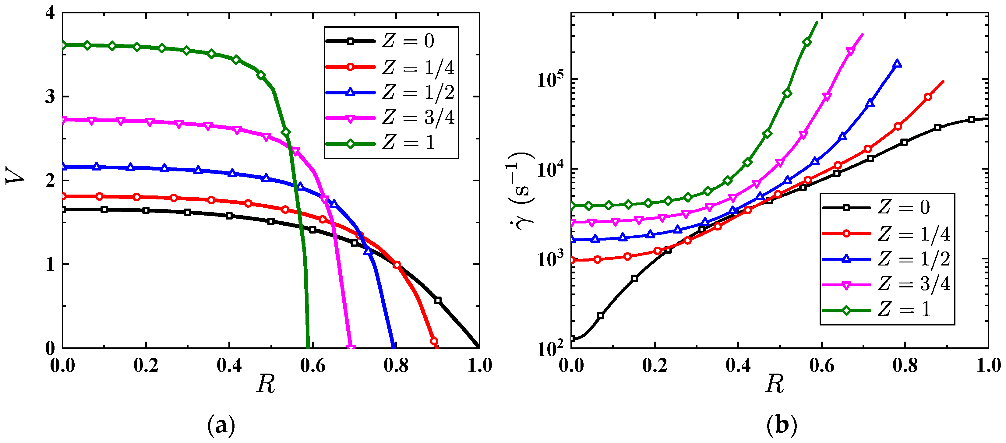
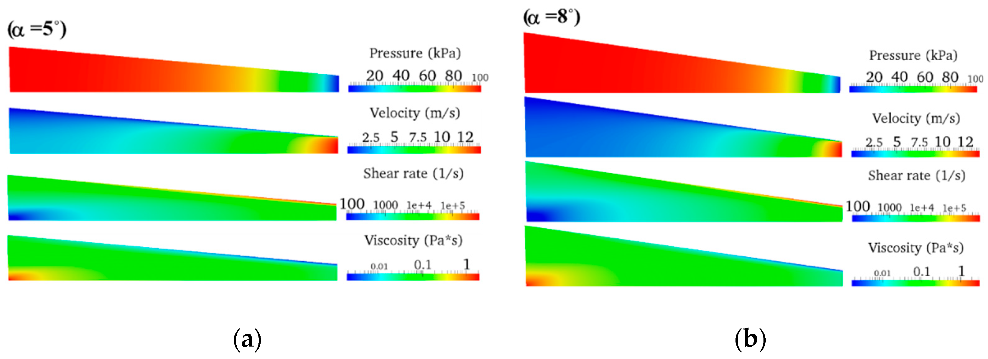
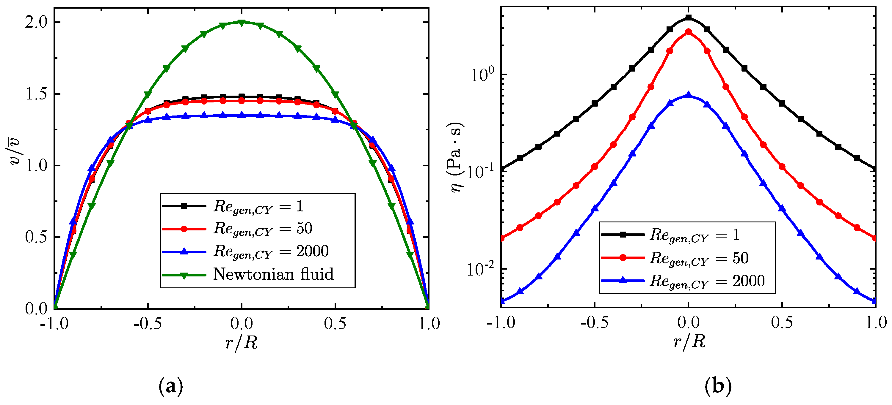
5.1. Converging Tube

We consider three different convergence angles: 2°, 5°and 8°, and each geometry is simulated for different pressure drops ranging from 1 bar to 6 bars. The inlet diameter is kept constant and chosen as the reference length. The length of the tube is L ¯ = L / R o = 20 . The typical flow contours of the water-HPC in a converging tube with 2° convergence angle with 1 bar pressure drop between the inlet and the outlet are shown in Figure 4. The velocity increases gradually and reaches the maximum value at the center line at the outlet (with the smallest radius). The shear rate varies at different locations in the flow. The shear rate at the exit wall is about 10,000 times the shear rate near the center of the entrance. The viscosity is also affected by shear rate in the Carreau-Yasuda model and is negatively proportional to the shear rate, therefore the viscosity is smallest at wall near the outlet.
The velocity and the shear rate profiles along the radial direction at different axial positions in the tube with 2° convergence angle are shown in Figure 5. Here, V is the ratio of the local velocity to the mean velocity at the inlet. From the variation of the velocity form inlet to outlet, an acceleration process can be observed. From Figure 5b, we can observe that the maximum shear rate appears at the wall near the outlet. The converging tube structure is adopted in conveying pipelines in order to reduce the gel viscosity and improve the delivery efficiency. Understanding the parameters which can cause a change in the viscosity is one of the key points in the converging tube flow studies. Figure 6 shows the viscosity variation along the radial and the flow directions in a 2° converging tube. According to Figure 5, the velocity gradient near the axis of the converging tube is small, and it reaches the maximum near the wall.
The higher shear rates would lead to a faster reduction of the viscosity near the walls, as shown in Figure 6a. From Figure 6b, it also can be observed that the viscosity decreases gradually along the axial (flow) direction, due to the convergence of the tube diameter causing an increase in the shear rate. On the other hand, it should be noticed that near the tube center at the outlet, the viscosity is still very high, which is a problem for spray atomization.
Figure 7, Figure 8 and Figure 9 investigate the effect of the convergence angle on the flow characteristics. The pressure, velocity, shear rate and viscosity fields in the converging tube with different convergence angles are shown in Figure 7. As the convergence angle increases, the viscosity decreases. Figure 8a plots the dimensionless pressure ( P = p / p i n ) profile along the axial direction with different convergent angles, where p i n is the pressure at the inlet. The pressure becomes more nonlinear as the convergence angle increases; this could be due to the fact that the pressure gradient increases near the inlet and the outlet as the tube diameter decreases, determined by the convergence angle. Therefore, we can observe that the pressure at the inlet with a larger cross section changes slightly while the pressure at the outlet with a smaller cross section changes greatly, and this is especially noticeable in tubes with a convergence angle of 8°. Figure 8b shows the profiles of the dimensionless mean velocity ( V = v ¯ / v ¯ i n ) along the axial direction with different convergent angles, where v ¯ is the cross-section mean velocity and v ¯ i n is the cross-section mean velocity at the inlet. We can see that the gradient of the dimensionless mean velocity increases with bigger convergences angles, which corresponds to a larger pressure gradient. The effect of the convergence angle on the mean apparent viscosity at the outlet is shown in Figure 9, (see Equation (9) for the definition of the mean apparent viscosity).
The mean apparent viscosity at the outlet can be reduced by increasing the convergence angle of the tube and the pressure drop ( Δ p ). Increasing Δ p can significantly lower the mean apparent viscosity while the effect reduces as Δ p increases further. The effect of the convergence angle on the mean apparent viscosity at the outlet is also significant. In the range of the convergence angle studied here, the mean apparent viscosity decreases almost linearly as the convergence angle increases. However, it should be noticed that the convergence angle of the tube must be limited within a certain range, because higher convergence angles cannot meet the requirement of mass flow rate. Therefore, a trade-off should be made between increasing the convergence angle and the viscosity reduction.

5.2. Tapered Injectors

In this section, we study another typical geometry used in propulsion systems: tapered injectors. The front straight tube is long enough for ensuring the fully developed flow condition before the converging tube. The criterion for the fully developed flow is that the gradient of the magnitude of the dimensionless velocity along the axial direction is less than 1e−3/m. The diameter of the front (straight) tube is chosen as the reference length. The diameter of the straight part after the converging part is R ¯ o = R o / R 1 = 0.1 and the length is Z ¯ = 20 . Five convergence angles are studied (shown in Table 2). Each geometry is numerically studied with the generalized Reynolds number of 0.127 to 0.911 at the inlet.
Figure 10 shows the contours of the pressure, velocity, shear rate and viscosity distribution with an inlet R e g e n , C Y = 0.391 and a convergence angle of 60°. In the front of the (straight) tube, the shear rate increases along the radial direction, and this leads to a high viscosity near the tube center where a “plunger” effect with high viscosity can be observed. In the converging section, the shear rate continues to increase while the viscosity keeps decreasing. Viscosity in the smaller straight tube remains at a low level because of the high shear rate. The variation of the flow along the axis of the slim tube can indicate the effect of the length of the slim tube on the mean apparent viscosity at the outlet. Figure 11 plots the radial distributions of velocity, shear rate and viscosity in the slim tube at different axial distances. Z ¯ is the ratio of the axial distances from the inlet of the slim tube to its diameter. The viscosity at the inlet remains small compared with those in the tube, due to the relative high shear rate caused by the disturbed flow at that region. The slim straight tube acts as a flow straightener and the velocity gradually becomes more parabolic after the gel enters this section of the tube, and as a result the shear rate decreases. The smaller shear rate causes the gel viscosity to return to a higher level, as shown in Figure 11c.
The mean apparent viscosity at different axial positions in the small tube is shown in Figure 12. The mean apparent viscosity at the outlet of the convergence tube is 0.0114 Pa·s. After entering the tube, the mean apparent viscosity rises rapidly to two times of that at the outlet of the converging tube; the length of the small tube has little effect on the mean apparent viscosity.
Therefore, for shear-thinning gels studied here, the existence of the small tube is unfavorable. When designing an injector, the small tube should be as short as possible for achieving the minimum mean apparent viscosity at the outlet. From last section of this paper, we have observed that the converging tube of the injector has a significant effect on the viscosity reduction. For the gels with a high viscosity, the high shear rate in the converging part of the injector can help the gel approach the lower-bound viscosity ( η ). Therefore, the effect of the convergence angle of the converging tube is investigated below. A central radial cross-section is defined at the middle of the inlet and the outlet of the converging part (also see the position of the cross-section indicated by the red dash line in Figure 3b). Figure 13 shows the effect of the convergence angles on the velocity, shear rate and viscosity profiles along the radial direction in the central cross-section and the outlet cross-section of the converging part. In Figure 13a, the velocity is non-dimensionalized based on the velocity at R = 0 . It can be seen, that as the convergence angle increases, the overall shear rate (velocity gradient) increases, which results in a lower viscosity. In Figure 13b, the velocity is non-dimensionalized based on the velocity at R = 0 as well. We can observe that the velocity distribution is far from being parabolic; the maximum velocity appears to be at the position of R 0.8 , therefore the shear rate near the wall is significantly higher than the shear rate in the main flow region, and as a result the viscosity near the wall is much lower, forming a lubrication layer for fluid flow.
Figure 14 shows the mean apparent viscosity along the axial direction with different convergent angles. Here, L ¯ is the ratio of the distance away from the entrance of the converging tube and the length of the converging tube. In Figure 14, we can observe that the mean apparent viscosity at the entrance of the converging part is the largest and it gradually decreases along the axial direction. The decrease of the mean apparent viscosity is more obvious with the bigger convergence angles; the converging tube with a 60° convergence angle gives the smallest mean apparent viscosity at the outlet, which is two orders of magnitude lower than that of the mean apparent viscosity at the inlet. Therefore, the injector plays an important role in reducing the viscosity of the gel.
To further illustrate the change of the pressure loss ( δ = ( p i p o ) / p i   × 100 % ) with the convergence angle, the pressure drop of different converging tubes is plotted as the black line in Figure 15, where we can observe that the pressure loss increases with the increase of the convergence angle. Meanwhile, the mean apparent viscosity represented by the red line in Figure 15 decreases with the increase of the convergence angle. The mean apparent viscosity of the tube with the convergence angle of 60° is only half of the one with the convergence angle of 20°. Increasing the convergence angle lowers the viscosity but causes higher pressure losses. Therefore, a balance between the pressure loss and the viscosity reduction should be taken into account for design of the injector geometry.
The effect of the Reynolds number (based on the flow conditions at the inlet of the whole tube) on the pressure loss and the mean apparent viscosity at the exit is represented in Figure 16. As the Reynolds number increases, the mean apparent viscosity decreases while the pressure drop increases. Therefore, similar to the convergence angle, a proper Reynolds number should be chosen depending on the specific requirement of the practical application.

6. Conclusions

In this paper, we studied the flow characteristics of gel in converging tubes and tapered injectors which are typical geometries in propulsion systems for propellant transport and spray. For safety considerations, water-HPC gel is used to mimics the kerosene gel. The water-HPC gel is modeled by using the Carreau–Yasuda model, and the model parameters are fitted with the experimental data measured by a rotational rheometer. According to the numerical studies, the mean apparent viscosity at the exit of the converging tube decreases with the increase of the convergence angle; but for higher convergence angles, the pressure drop is increased. For the tapered injector, we find that the small pipe after the converging part has a detrimental effect on the viscosity reduction. Furthermore, both higher convergence angles and higher Reynolds numbers lead to smaller mean apparent viscosity and a high-pressure loss; therefore, for design purposes or for engineering operations a balance between the pressure loss and the viscosity reduction should be sought.

Author Contributions

Q.-L.C. developed the framework of the paper and did the numerical simulations. M.M. and W.-T.W. derived the equations. Q.-L.C., M.M., W.-H.L., F.F. and W.-T.W. prepared the manuscript.

Funding

This research received no external funding.

Conflicts of Interest

The authors declare no conflict of interest.

Appendix A

Figure A1a,b show the steady fully developed flow where the dimensionless velocity and viscosity profiles along the radial direction in a tube using the water-HPC. We can observe that the velocity profiles for the non-Newtonian fluid are very different compared to the profiles for a Newtonian fluid; moreover, the numerical results of the non-Newtonian fluid can also reveal the distribution of the gel viscosity; this is an important parameter for the design of transport tubes and injectors for propellent systems.
Figure A1. (a) Fully developed and steady-state dimensionless velocity and (b) viscosity profiles along the radial direction in a circular tube.
Energies 12 01643 g0a1

References

  1. Ferry, J.D.; Ferry, J.D. Viscoelastic Properties of Polymers; John Wiley & Sons: Hoboken, NJ, USA, 1980. [Google Scholar]
  2. Natan, B.; Rahimi, S. The status of gel propellants in year 2000. Int. J. Energ. Mater. Chem. Propuls. 2009, 5, 172–194. [Google Scholar] [CrossRef]
  3. Arnold, R.; Anderson, W. Droplet burning of JP-8/Silica gels. In Proceedings of the 48th 2010 AIAA Aerospace Sciences Meeting Including the New Horizons Forum and Aerospace Exposition, Orlando, FL, USA, 4–7 January 2010; pp. 1–12. [Google Scholar]
  4. Yang, L.J.; Fu, Q.F.; Qu, Y.Y.; Zhang, W.; Du, M.L.; Xu, B.R. Spray characteristics of gelled propellants in swirl injectors. Fuel 2012, 97, 253–261. [Google Scholar] [CrossRef]
  5. Nahamoni, G.; Natan, B.; Nahamoni, G.; Natan, B. Investigation of the combustion process of gel propellants. In Proceedings of the 33rd Joint Propulsion Conference and Exhibit, Seattle, WA, USA, 6–9 July 1997; p. 2973. [Google Scholar]
  6. Ciezki, H.K.; Naumann, K.W.; Weiser, V. Status of Gel Propulsion in the Year 2010 with a Special View on the German Activities. In Proceedings of the 2010 Deutschen Luft-und Raumfahrtkongress, Hamburg, Germany, 31 Agust–2 September 2010. [Google Scholar]
  7. Ciezki, H.K.; Negri, M.; Weiser, V.; Naumann, K.W.; Program, P.T.; Program, T.; Grund, L.; Heterogenious, H.; Group, S.; Grund, L.; et al. Overview of the German Gel Propulsion Technology. In Proceedings of the 50th AIAA/ASME/SAE/ASEE Joint Propulsion Conference, Cleveland, OH, USA, 28–30 July 2014; pp. 1–16. [Google Scholar]
  8. Rahimi, S.; Hasan, D.; Peretz, A. Development of Laboratory-Scale Gel Propulsion Technology. J. Propuls. Power 2008, 20, 93–100. [Google Scholar] [CrossRef]
  9. Naumann, K.W.; Ramsel, J.; Pinto, P.C.; Niedermaier, H.; Thumann, A. Gelled Green Propellant Rocket Motor and Gas Generator Technology at Bayern-Chemie-Status and Applications for Space Systems. In Proceedings of the 50th AIAA/ASME/SAE/ASEE Joint Propulsion Conference, Cleveland, OH, USA, 28–30 July 2014; p. 3796. [Google Scholar]
  10. Kubal, T.; Arnold, R.; Pourpoint, T.; Campanella, O.; Anderson, W. Rheological Characterization of Hydroxypropylcellulose/Monomethylhydrazine and\r\nSilica/Red Fuming Nitric Acid Gels. In Proceedings of the 46th AIAA/ASME/SAE/ASEE Joint Propulsion Conference & Exhibit, Nashville, TN, USA, 25–28 July 2010; p. 7140. [Google Scholar]
  11. Mishra, D.P.; Patyal, A.; Padhwal, M. Effects of gellant concentration on the burning and flame structure of organic gel propellant droplets. Fuel 2011, 90, 1805–1810. [Google Scholar] [CrossRef]
  12. Gafni, G.; Kuznetsov, A.; Har-Lev, D.; Natan, B. Experimental Investigation of a Ramjet Combustor Using an Aluminized Gel Fuel. In Proceedings of the 49th AIAA/ASME/SAE/ASEE Joint Propulsion Conference, San Jose, CA, USA, 14–17 July 2013; p. 3748. [Google Scholar]
  13. Matsibeker, E.; Natan, B. Numerical Solution of the Flowfield in an Aluminized Gel Fuel Ramjet. In Proceedings of the 49th AIAA/ASME/SAE/ASEE Joint PropulsionConference, San Jose, CA, USA, 14–17 July 2013; p. 3976. [Google Scholar]
  14. Natan, B.; Haddad, A.; Arieli, R. Performance assessments of a boron containing gel fuel ramjet. In Proceedings of the 47th AIAA Aerospace Sciences Meeting Including The New Horizons Forum and Aerospace Exposition, Orlando, FL, USA, 5–8 January 2009; p. 1421. [Google Scholar]
  15. Wu, W.-T.; Yang, F.; Antaki, J.F.; Aubry, N.; Massoudi, M. Study of blood flow in several benchmark micro-channels using a two-fluid approach. Int. J. Eng. Sci. 2015, 95, 49–59. [Google Scholar] [CrossRef] [Green Version]
  16. Wu, W.-T.; Zhou, Z.-F.; Aubry, N.; Antaki, J.F.; Massoudi, M. Heat transfer and flow of a dense suspension between two cylinders. Int. J. Heat Mass Transf. 2017, 112, 597–606. [Google Scholar] [CrossRef]
  17. Yan, C.; Altunbas, A.; Yucel, T.; Nagarkar, R.P.; Schneider, J.P.; Pochan, D.J. Injectable solid hydrogel: Mechanism of shear-thinning and immediate recovery of injectable β-hairpin peptide hydrogels. Soft Matter 2010, 6, 5143–5156. [Google Scholar] [CrossRef] [PubMed]
  18. Yoon, C.; Heister, S.; Sojka, P.; Watson, C.; Xia, G.; Merkle, C. Injector Flow Characteristics for Gel Propellants. In Proceedings of the 47th AIAA/ASME/SAE/ASEE Joint Propulsion Conference & Exhibit, San Diego, CA, USA, 31 July–3 August 2011. [Google Scholar]
  19. Doi, M. Explanation for the 3.4-power law for viscosity of polymeric liquids on the basis of the tube model. J. Polym. Sci. Polym. Phys. Ed. 1983, 21, 667–684. [Google Scholar] [CrossRef]
  20. Doi, M. Explanation for the 3.4 power law of viscosity of polymeric liquids on the basis of the tube model. J. Polym. Sci. Polym. Lett. Ed. 1981, 19, 265–273. [Google Scholar] [CrossRef]
  21. Krieger, I.M. Rheology of monodisperse latices. Adv. Colloid Interface Sci. 1972, 3, 111–136. [Google Scholar] [CrossRef]
  22. Rahimi, S.; Natan, B. Numerical solution of the flow of power-law gel propellants in converging injectors. Propellants Explos. Pyrotech. 2000, 25, 203–212. [Google Scholar] [CrossRef]
  23. Rahimi, S.; Natan, B.; Rahimi, S.; Natan, B. The injection process of gel fuels. In Proceedings of the 33rd Joint Propulsion Conference and Exhibit, Seattle, WA, USA, 6–9 July 1997; p. 2972. [Google Scholar]
  24. Rahimi, S.; Natan, B. Flow of gel fuels in tapered injectors. J. Propuls. Power 2000, 16, 458–464. [Google Scholar] [CrossRef]
  25. Yoon, C.; Heister, S.D.; Xia, G.; Merkle, C.L. Numerical modeling of injection of shear-thinning gel propellants through plain-orifice atomizer. J. Propuls. Power 2011, 27, 944–954. [Google Scholar]
  26. Beg, O.A.; Motsa, S.S.; Islam, M.N.; Lockwood, M. Pseudo-spectral and variational iteration simulation of exothermically-reacting Rivlin-Ericksen viscoelastic flow and heat transfer in a rocket propulsion duct. Comput. Therm. Sci. Int. J. 2014, 6, 91–102. [Google Scholar] [CrossRef]
  27. Chernov, V.; Natan, B. Estimation of the rheological properties of a suspension in a gel fluid. AIAA J. 2013, 51, 998–1003. [Google Scholar] [CrossRef]
  28. Yoon, C.; Heister, S.D.; Campanella, O.H. Modeling gelled fluid flow with thixotropy and rheological hysteresis effects. Fuel 2014, 128, 467–475. [Google Scholar] [CrossRef]
  29. Von Kampen, J.; Madlener, K.; Ciezki, H.K. Characteristic Flow and Spray Properties of Gelled Fuels. In Proceedings of the 42nd AIAA/ASME/SAE/ASEE Joint Propulsion Conference & Exhibit, Sacramento, CA, USA, 9–12 July 2006; pp. 1–12. [Google Scholar] [CrossRef]
  30. Yoon, C.; Heister, S.D.; Merkle, C.L.; Xia, G. Simulations of Plain-Orifice Injection of Gelled Propellants Under Manifold Crossflow Conditions. J. Propuls. Power 2012, 29, 136–146. [Google Scholar] [CrossRef]
  31. Wu, W.T.; Aubry, N.; Massoudi, M. Flow of granular materials modeled as a non-linear fluid. Mech. Res. Commun. 2013, 52, 62–68. [Google Scholar] [CrossRef]
  32. Slattery, J.C. Advanced Transport Phenomena; Cambridge University Press: Cambridge, UK, 1999. [Google Scholar]
  33. Buongiorno, J. Convective Transport in Nanofluids. J. Heat Transf. 2006, 128, 240–250. [Google Scholar] [CrossRef]
  34. Massoudi, M. Heat transfer in complex fluids. In Two Phase Flow, Phase Change and Numerical Modeling; INTECH Open Access Publisher: Rijeka, Croatia, 2011. [Google Scholar]
  35. Fung, Y.C. Biomechanics: Mechanical Properties of Living Tissues, 2nd ed.; Springer: New York, NY, USA, 1993. [Google Scholar]
  36. Houwink, R. Elasticity, Plasticity and Structure of Matter, 2nd ed.; Harren Press: Washington, DC, USA, 1953. [Google Scholar]
  37. Roscoe, R. Suspensions, flow properties of disperse systems. In Flow Properties of Disperse Systems; North. Holl. Publ. Company: Amsterdam, The Netherlands, 1953. [Google Scholar]
  38. Arnold, R.; Anderson, W.; Santos, P.H.S.; deRidder, M.; Campanella, O.H. Comparison of Monomethylhydrazine/hydroxypropylcellulose and Hydrocarbon/silica Gels. In Proceedings of the 48th AIAA Aerospace Sciences Meeting Including the New Horizons Forum and Aerospace Exposition, Orlando, FL, USA, 4–7 January 2010; p. 422. [Google Scholar]
  39. Fiordilino, J.; Massoudi, M.; Vaidya, A. On the heat transfer and flow of a non-homogenous fluid. Appl. Math. Comput. 2014, 243, 184–196. [Google Scholar] [CrossRef]
  40. Wu, W.-T.; Aubry, N.; Antaki, J.F.; McKoy, M.L.; Massoudi, M. Heat Transfer in a Drilling Fluid with Geothermal Applications. Energies 2017, 10, 1349. [Google Scholar] [CrossRef]
  41. OpenCFD. OpenFOAM Programmer’s Guide Version 2.1.0; OpenCFD, Ed.; Free Software Foundation, Inc.: Boston, MA, USA, 2011. [Google Scholar]
Figure 1. Sample of Water-HPC gel containing 1.5 wt% HPC and 98.5 wt% water.
Energies 12 01643 g001
Figure 2. Viscosity measurement of water-HPC gel.
Energies 12 01643 g002
Figure 3. Geometries of (a) the converging tube and (b) the tapered injectors. R i and R o are radii of the inlet and the outlet cross-section, respectively. α and L are the convergence angle and the length of converging part, and Z is the length of the straight pipe after converging part.
Energies 12 01643 g003
Figure 4. Contours of pressure, velocity, shear rate and viscosity in the tube with a convergence angle of 2° with a 1bar pressure drop.
Energies 12 01643 g004
Figure 5. (a) Velocity and (b) shear rate profiles along the radial direction at different axial positions. Z = z/L, α = 2°, and Δ p = 1 bar.
Energies 12 01643 g005
Figure 6. Viscosity profiles of the water-HPC gel (a) along the radial direction at different axial positions and (b) along the axial direction at different radial positions. Z = z/L, R = r/r(z), α = 2°, and Δ p = 1 bar.
Energies 12 01643 g006
Figure 7. Contours of pressure, velocity, shear rate and viscosity in the (a) 5° and (b) 8° converging tube, R o = 0.4   mm , Δ p   = 1 bar.
Energies 12 01643 g007
Figure 8. (a) Dimensionless pressure distribution, P = p / p i n and (b) dimensionless mean velocity of cross section along the tube axis, V = v ¯ / v ¯ i n . p i n is the pressure at the inlet, and v ¯ is the cross-section mean velocity and v ¯ i n is the cross-section mean velocity at the inlet.
Energies 12 01643 g008
Figure 9. Effect of the convergence angle and the pressure drop on the mean apparent viscosity at the tube exit.
Energies 12 01643 g009
Figure 10. Contours of flow fields in the tapered injector with R ¯ o = R o / R i = 0.1 , Z ¯   =   Z / R O   = 20 , α = 60°, inlet R e g e n , C Y = 0.391 .
Energies 12 01643 g010
Figure 11. (a) Velocity, (b) shear rate and (c) viscosity profiles along the radial direction at various axial locations in the small tube,   R ¯ o = R o / R i = 0.1 , Z ¯ = Z / R O = 20 , α = 60°, inlet R e g e n , C Y = 0.391 .
Energies 12 01643 g011
Figure 12. Mean apparent viscosity and pressure distributions along the axial location of the small tube,   R ¯ o = R o / R i = 0.1 , Z ¯ = Z / R O = 20 , α = 60°, inlet R e g e n , C Y = 0.391 .
Energies 12 01643 g012
Figure 13. Velocity, shear rate and viscosity profiles along the radial direction on (a) the central cross-section and (b) the exit cross-section of the converging stage, R ¯ o = R o / R i = 0.1 , inlet R e g e n , C Y = 0.391 .
Energies 12 01643 g013
Figure 14. Variation of the mean apparent viscosity along the axial direction for different convergent angles.
Energies 12 01643 g014
Figure 15. Effect of the convergence angle on the pressure loss ( δ ) and the mean apparent viscosity ( η ¯ ) at the outlet of the convergence tube with inlet R e g e n , C Y = 0.391 .
Energies 12 01643 g015
Figure 16. Effect of the Reynolds number (Regen,CY) on the mean apparent viscosity and the pressure drop with the convergence angle of 60°.
Energies 12 01643 g016
Table 1. Fluid type and the corresponding C-Y parameters.
Fluid Type (Weight-Based)The Carreau-Yasuda Parameters
η0, Pa·sη, mPa·saλn
Water + 1.5%HPC5.8820.8950.6920.1490.267
Table 2. Various geometric parameters for the converging tube and the tapered injectors.
GeometriesConverging TubeTapered Injector
Convergence angle ( α , °)2, 5, 820, 30, 40, 50, 60
Table 3. Boundary conditions used in the numerical simulations.
Boundary TypeConverging Tube
PressureVelocity
WallZero gradientFixed value (0)
InletFixed valueZero gradient
OutletFixed valueZero gradient
Boundary typeTapered injector
PressureVelocity
WallZero gradientFixed value (0)
InletZero gradientFixed value
OutletFixed valueZero gradient
Table 4. Mesh dependency study.
LabelGrid NumberMean Velocity at Tube Exit (m/s)Mean Apparent Viscosity at Tube Exit (Pa·s)
Grid A167,02912.385450.024526
Grid B384,56912.420030.024528
Grid C691,50912.350380.024543
Grid D1,087,84912.413360.024582

