Modelling and Evaluation of Waste Heat Recovery Systems in the Case of a Heavy-Duty Diesel Engine

 ,
,  ,
,  and
and
Abstract
:1. Introduction
- Mechanical turbo-compounding
- Electrical turbo-compounding
- Thermoelectric generators (TEG)
- Steam Rankine cycle
- Organic Rankine cycle (ORC)
- Brayton thermodynamic cycle
1.1. Waste Heat Recovery
1.2. Steam/Organic Rankine Cycle
1.3. Organic Rankine Cycle and Internal Combustion Engines
1.4. Engine Turbocompounding
1.4.1. Electrical Turbo-Compounding
1.4.2. Mechanical Turbo-Compounding
2. Engine Waste Heat Recovery System Modelling
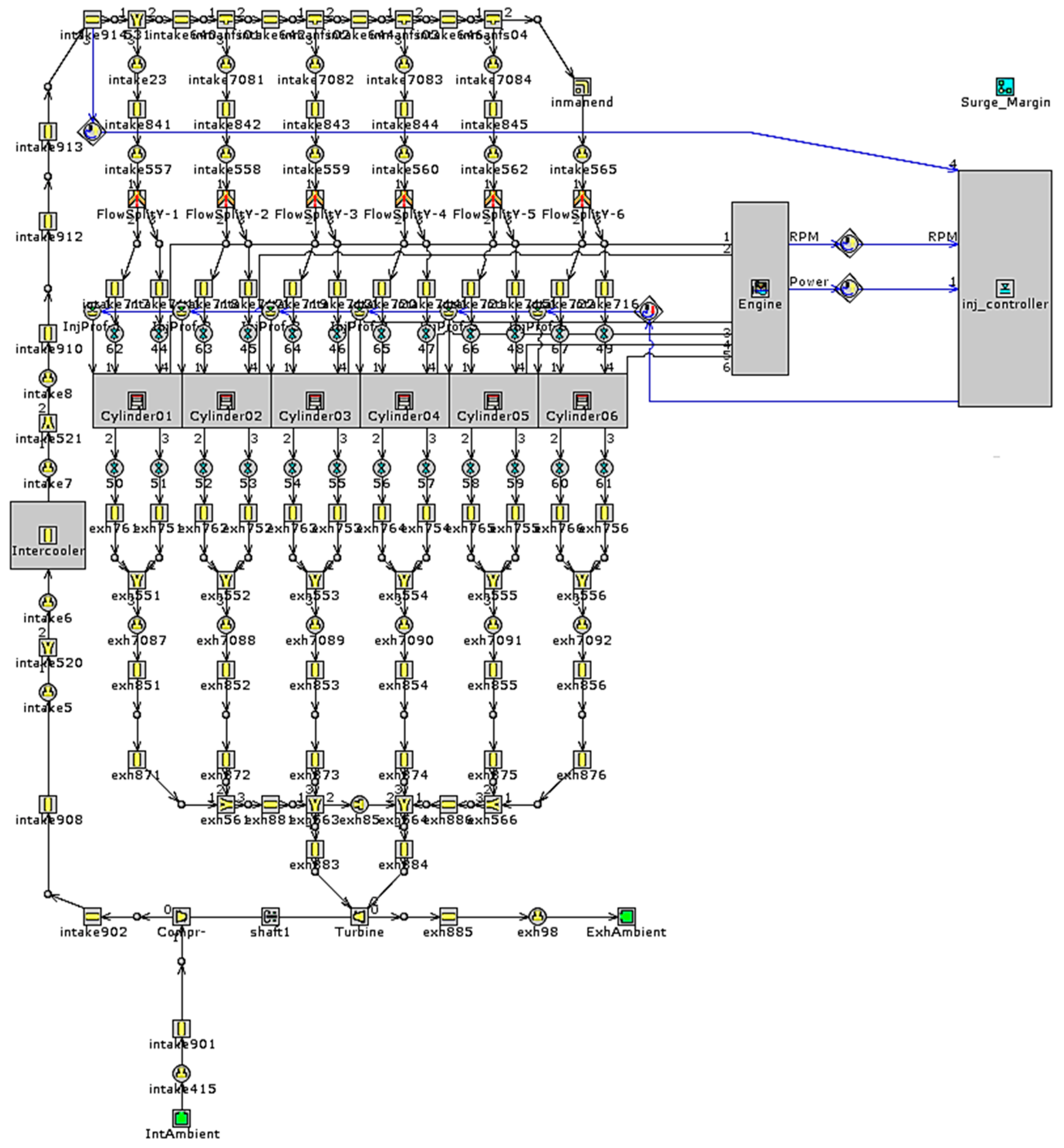
2.1. Engine Modelling and Calibration
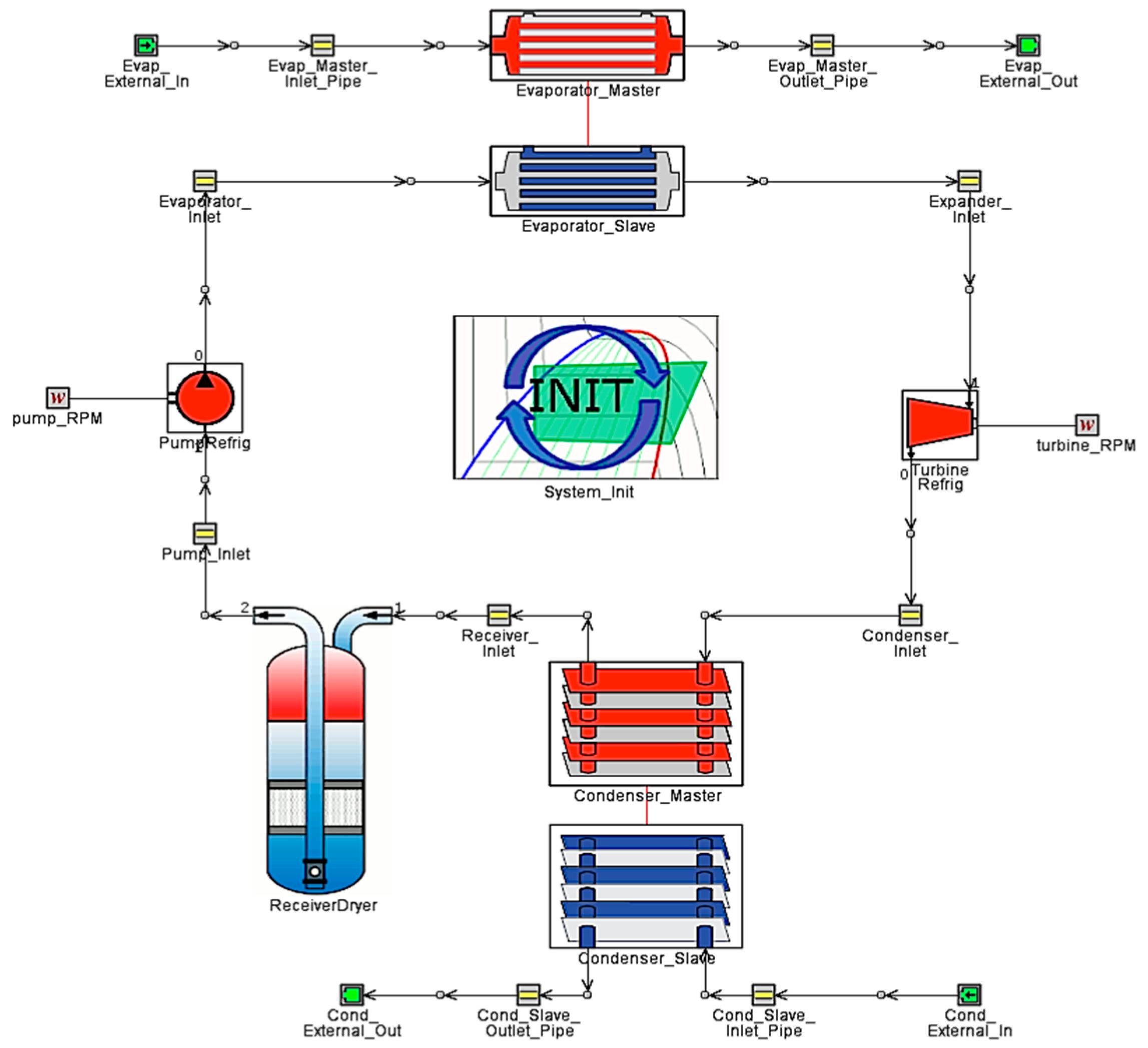
2.2. ORC System Modelling
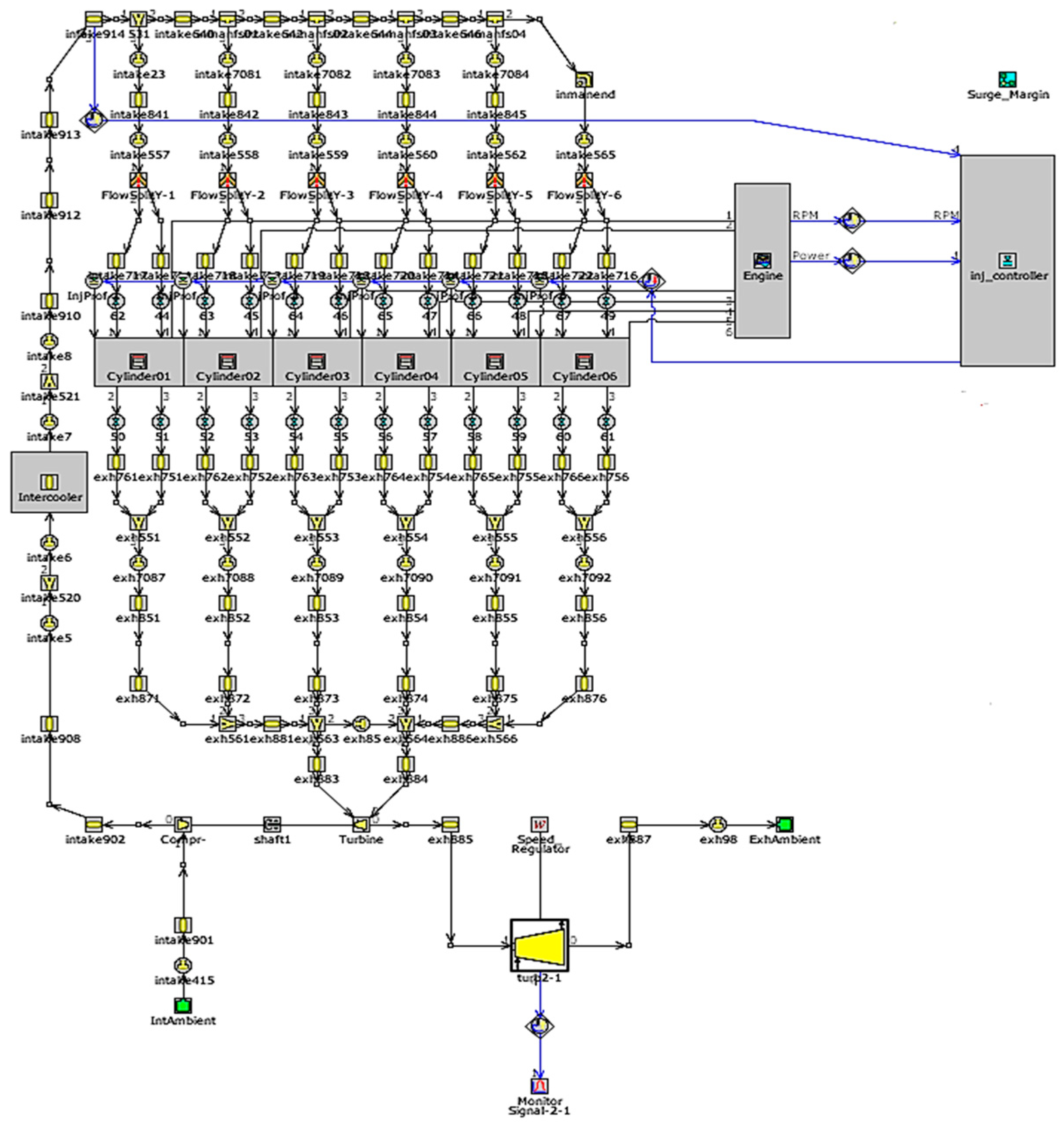
2.3. Turbocompound System Modelling
3. Results and Discussion
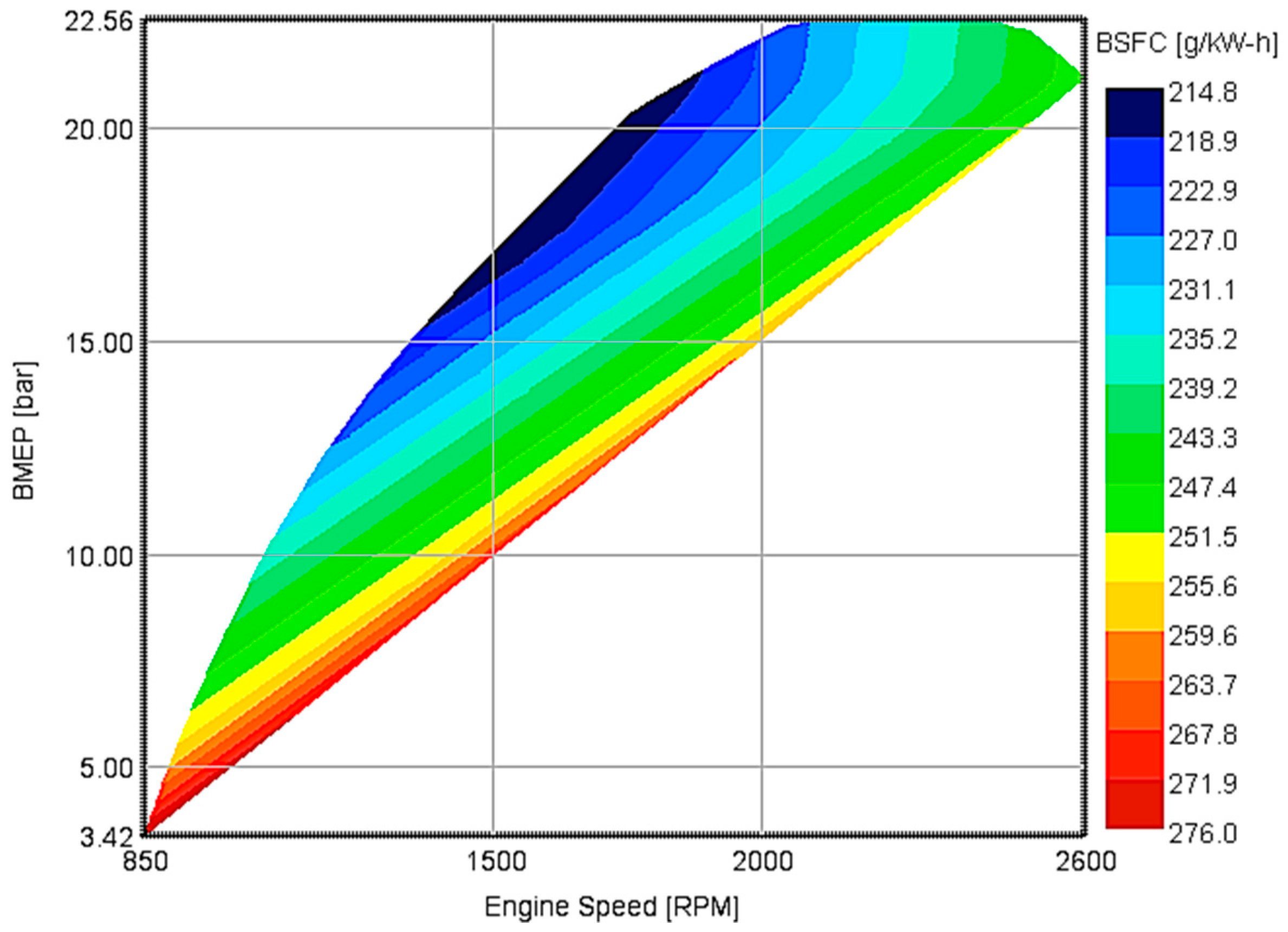
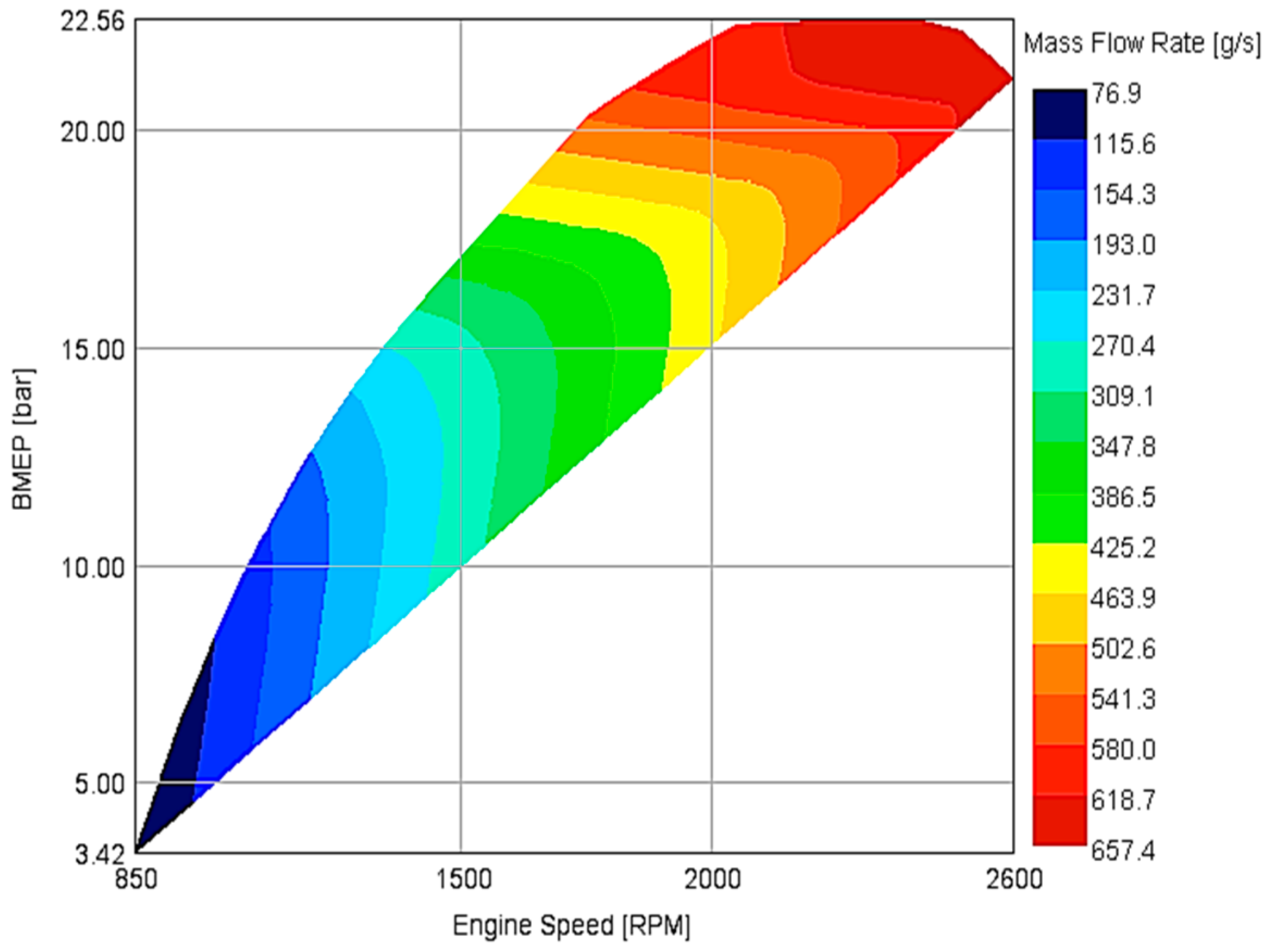
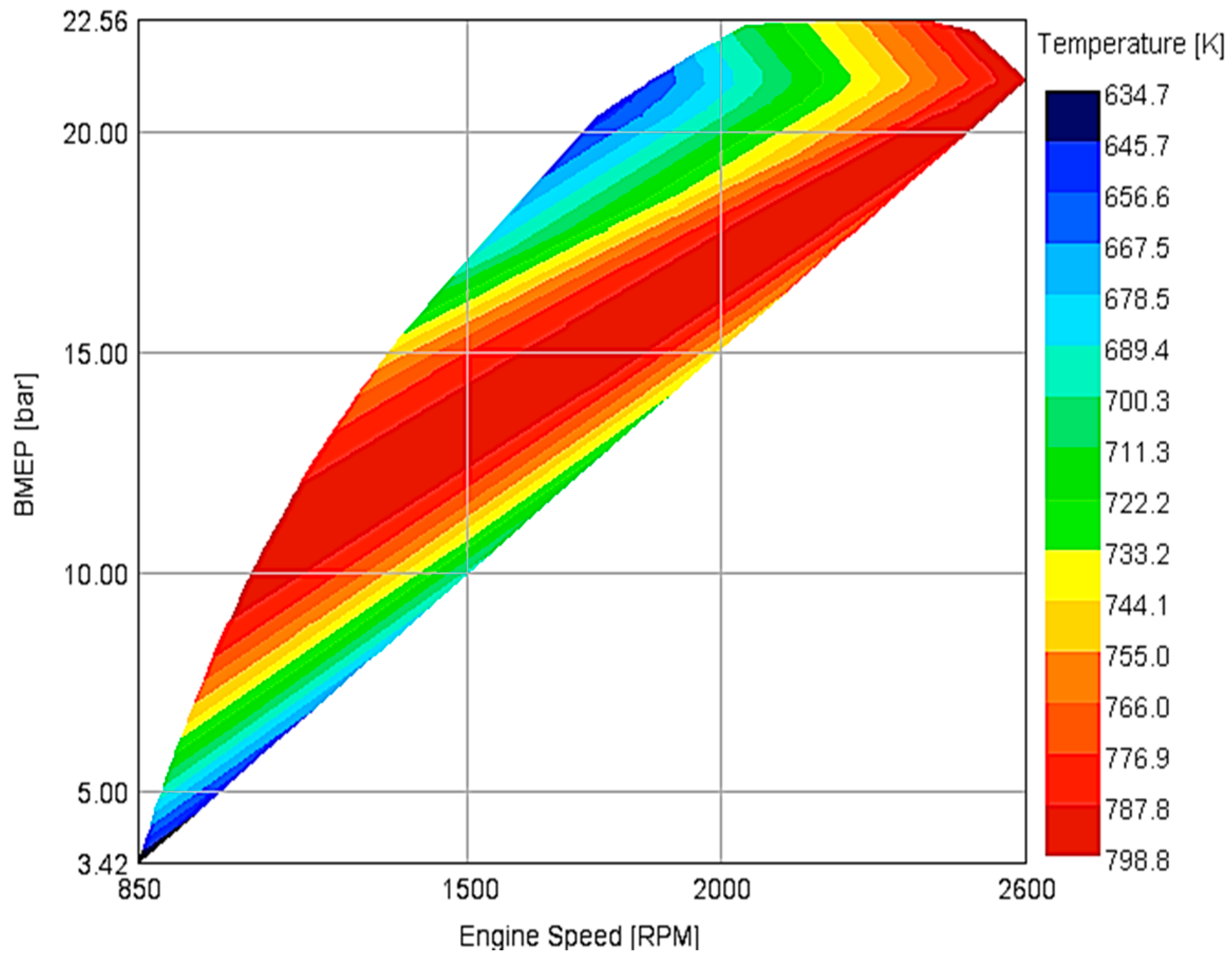
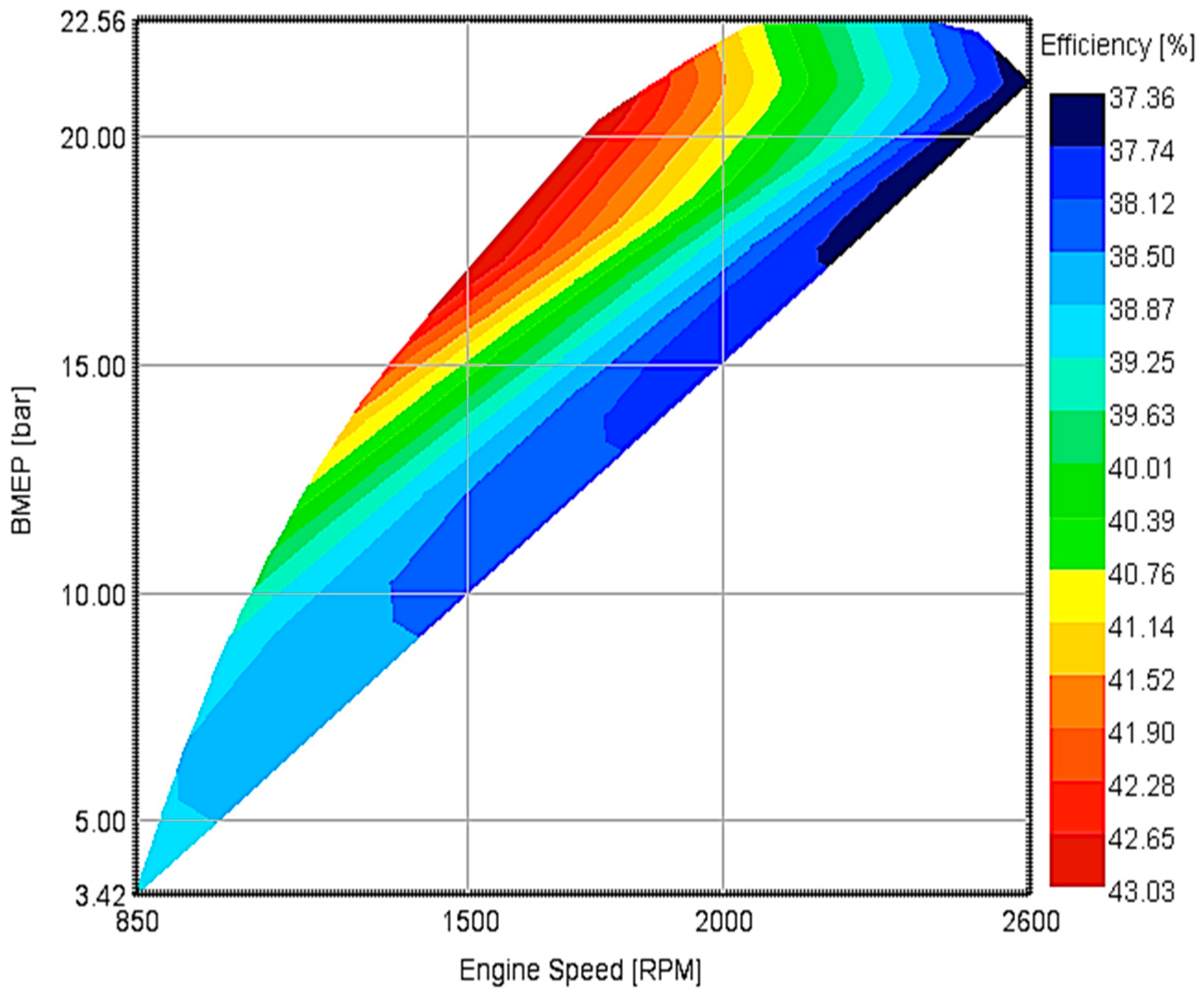
3.1. Engine Waste Heat
3.2. Organic Rankine Cycle System
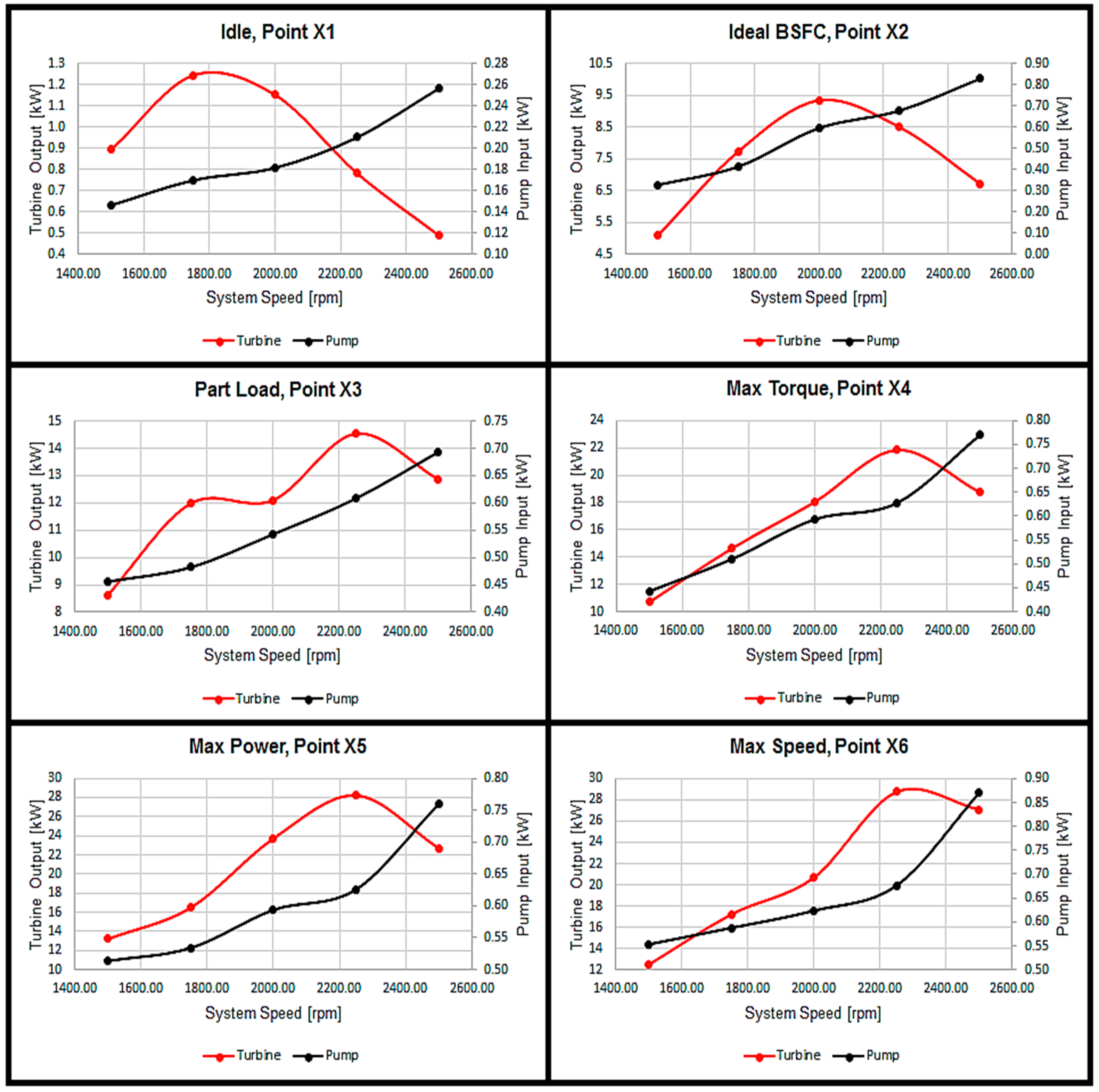
3.2.1. ORC System Speed Variation
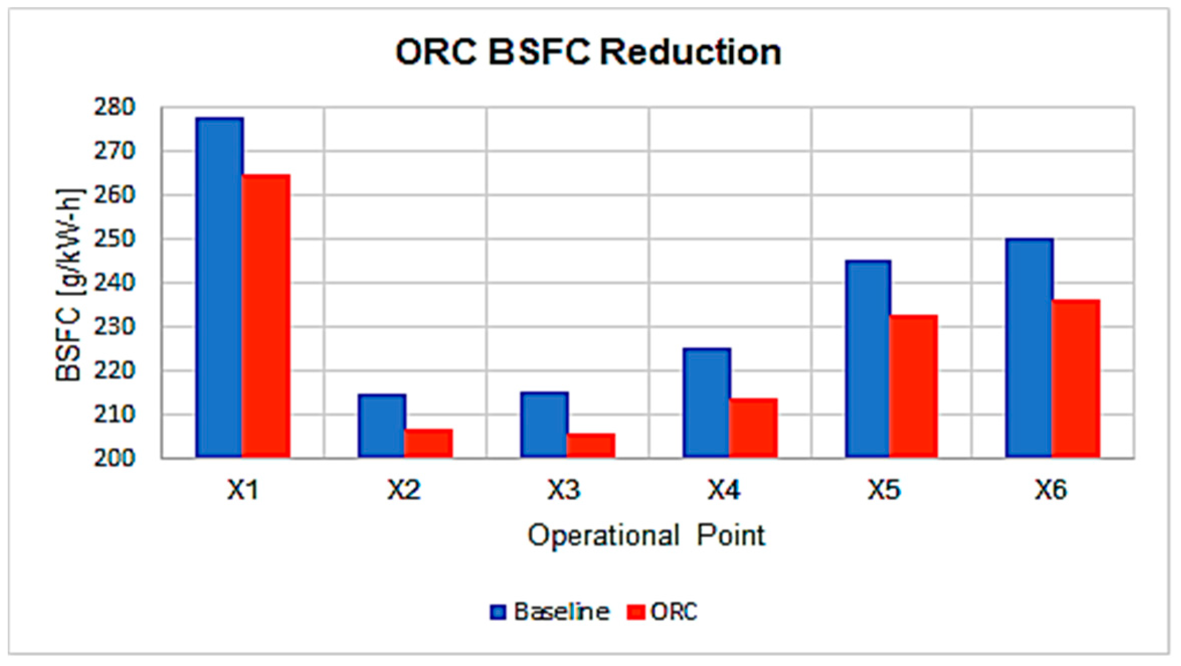
3.2.2. ORC System BSFC Reduction
3.3. Turbo-Compound System
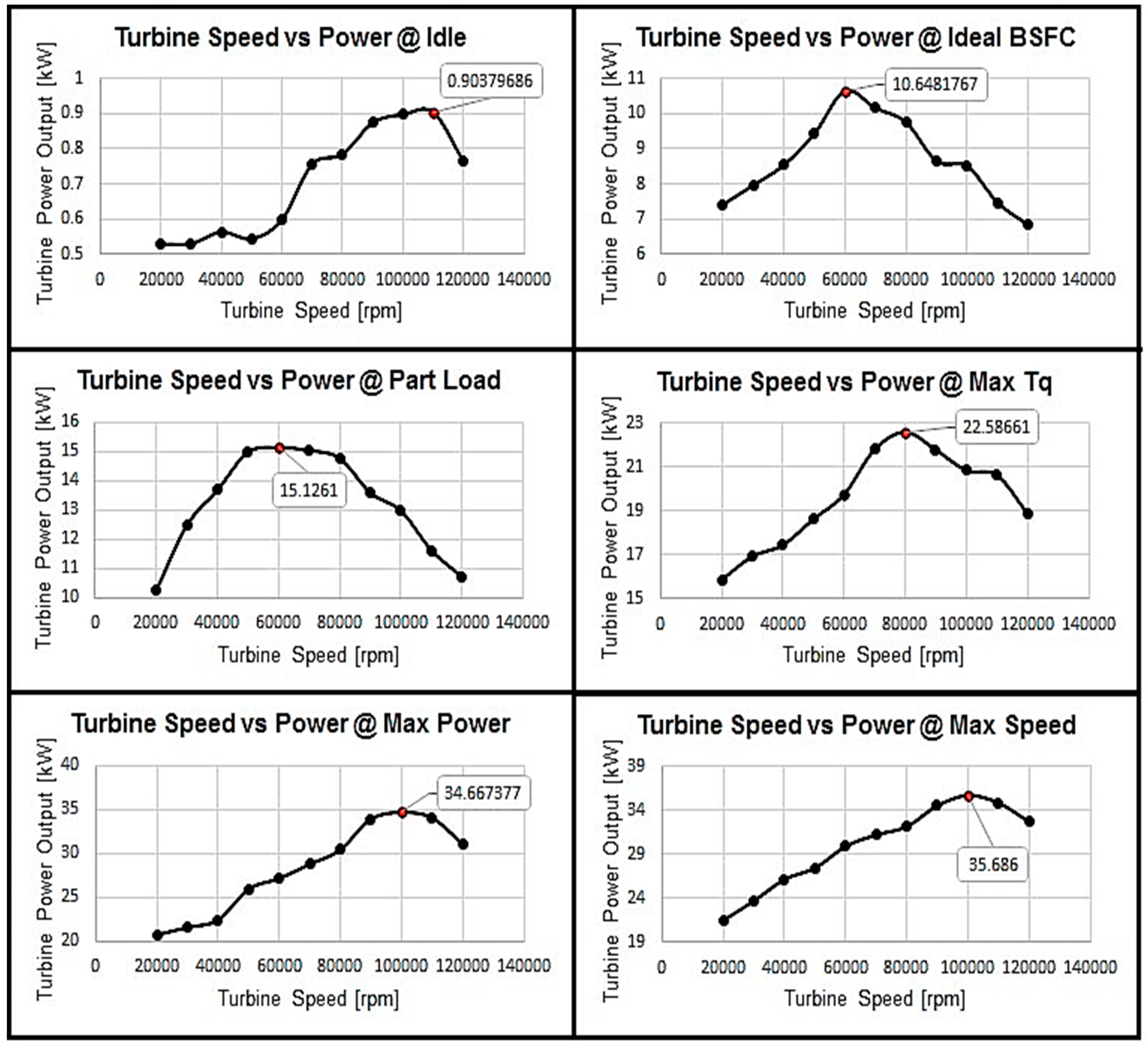
3.3.1. Turbo-Compound System Speed Variation
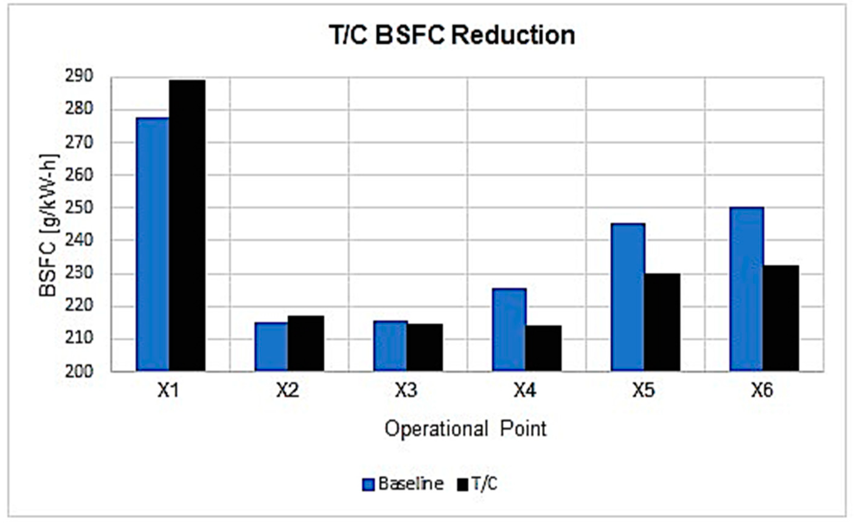
3.3.2. Turbo-Compound System BSFC Reduction
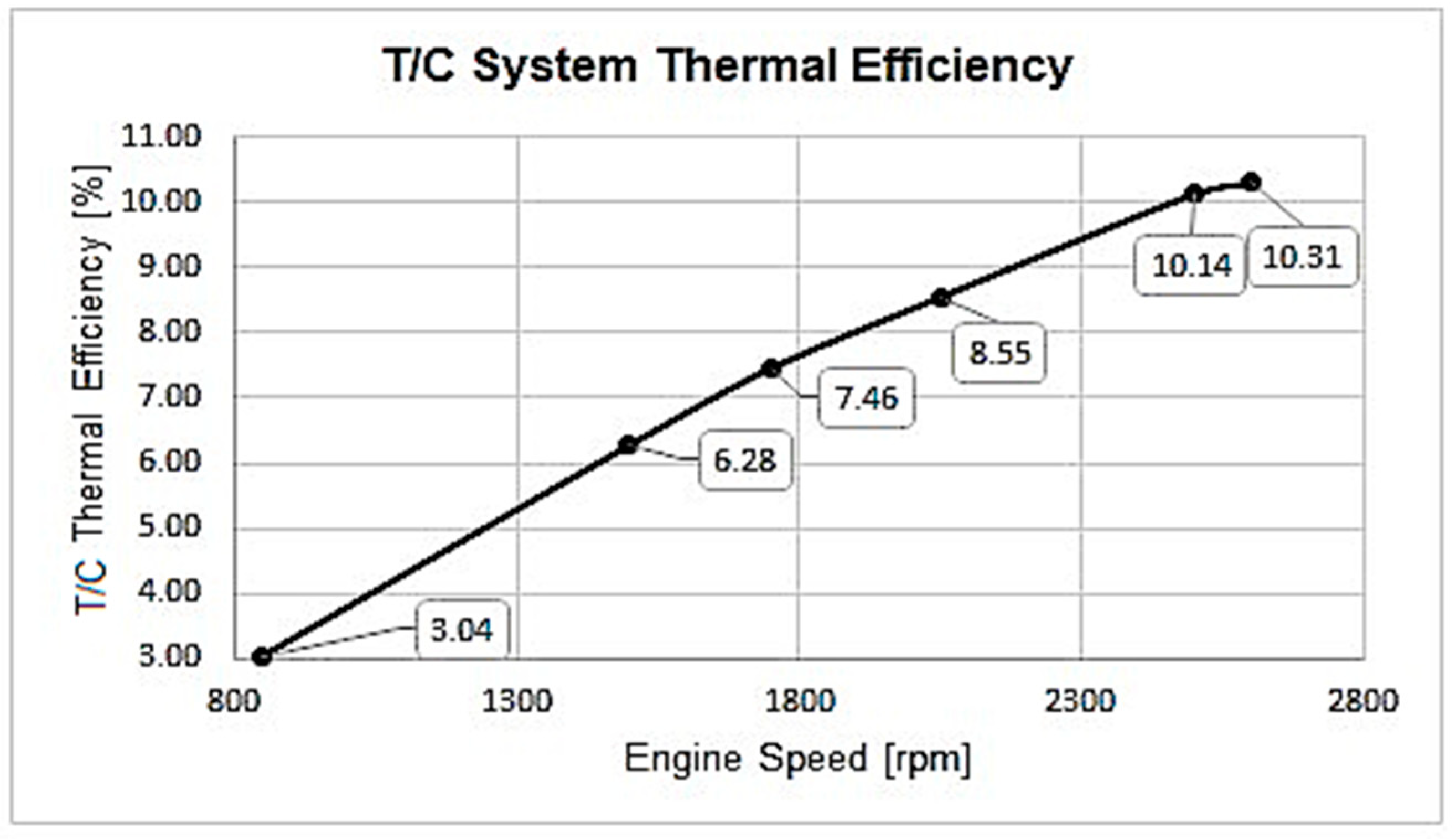
3.3.3. Turbo-Compound System Efficiency
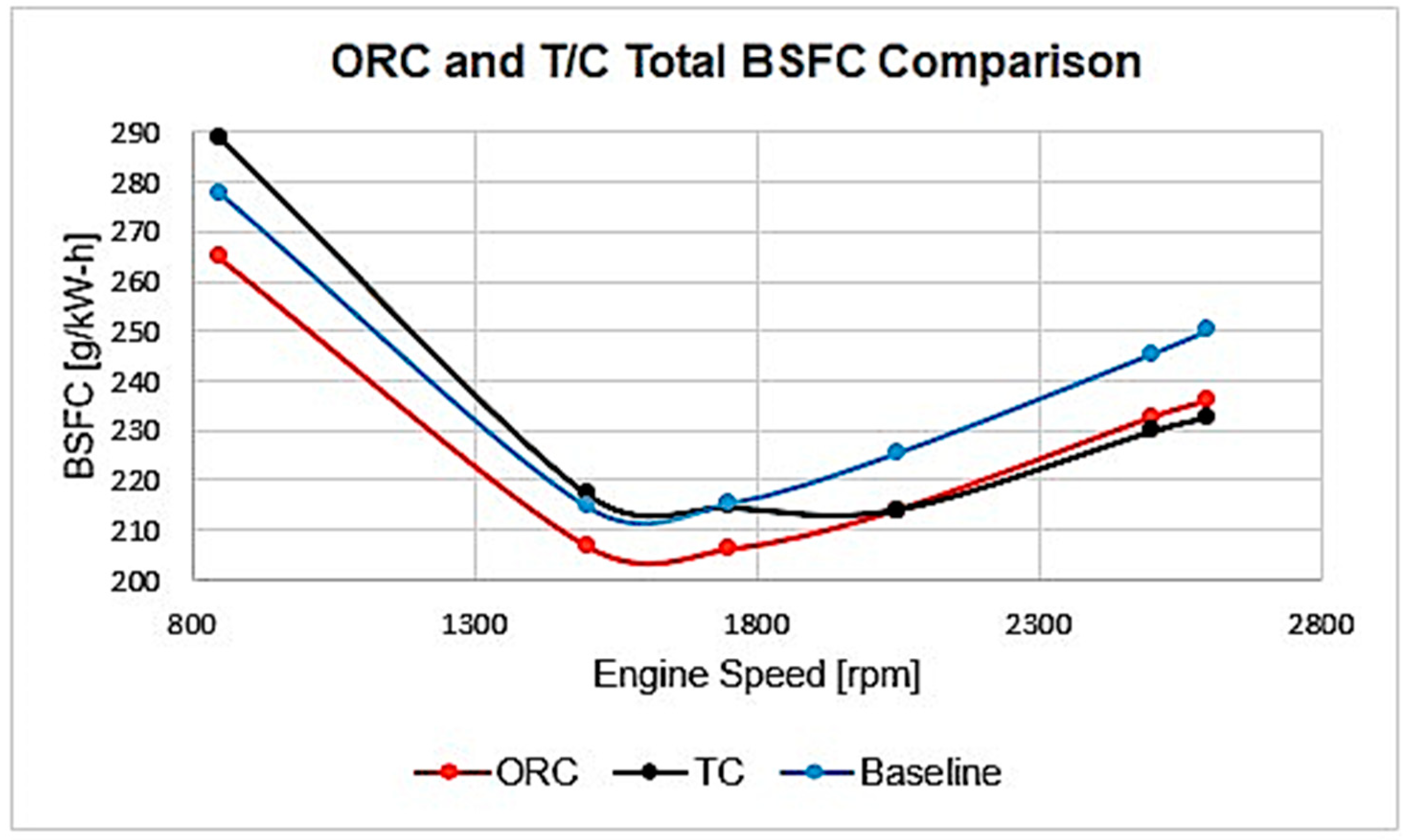
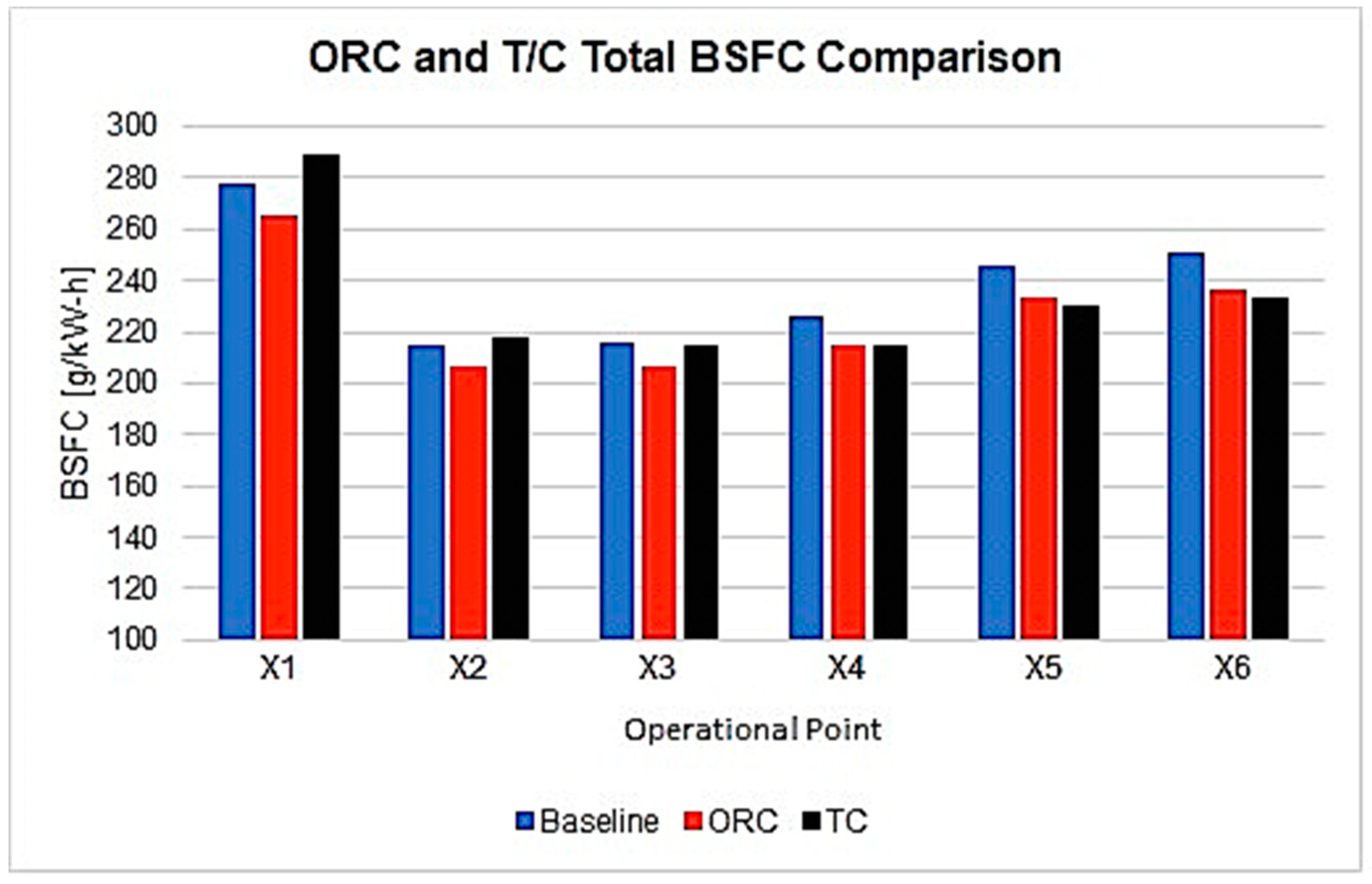
3.4. ORC T/C System vs. ORC System Comparison
4. Conclusions
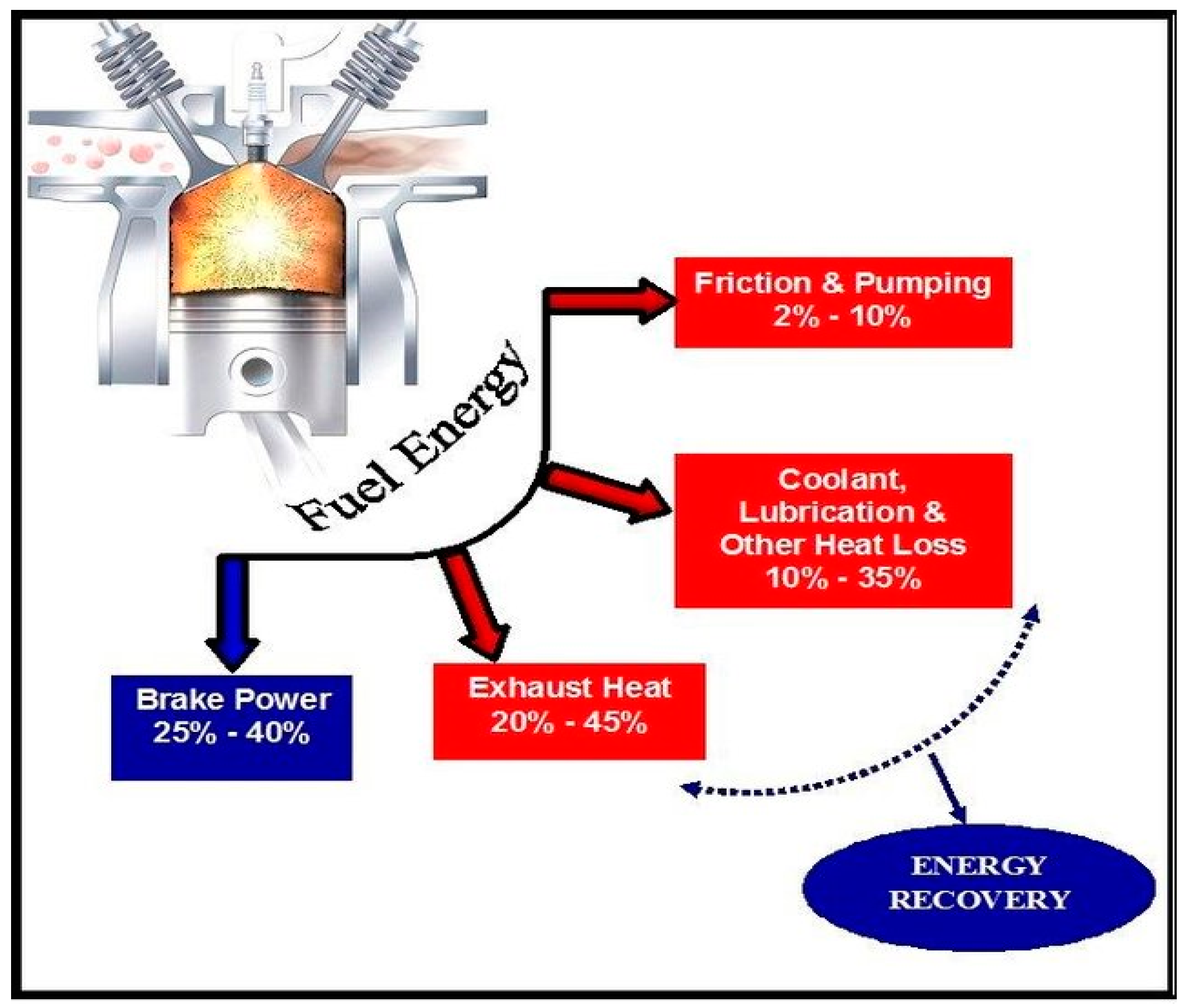
- The capability to regenerate power is determined by the availability of exhaust energy at the systems inlet conditions. That availability is reduced at ideal BSFC regions and increased during top end engine speeds.
- Exhaust energy is directly proportional to exhaust gas temperature and mass flow rate, however only the latter administers the greatest impact; temperature remains relatively unchanged across the engines’ range.
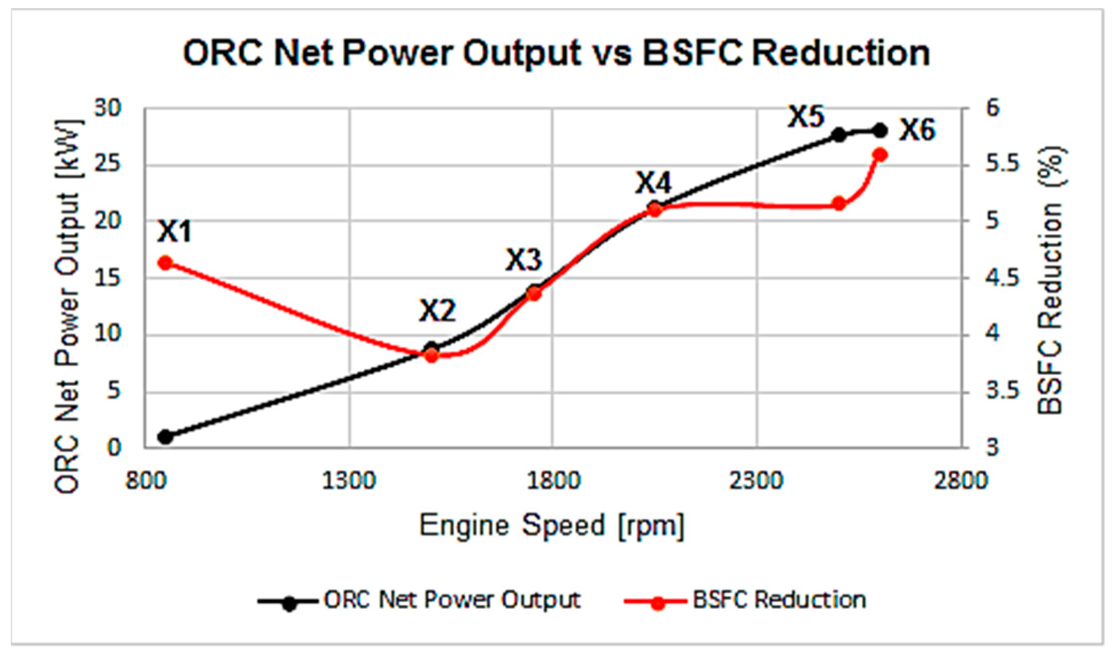
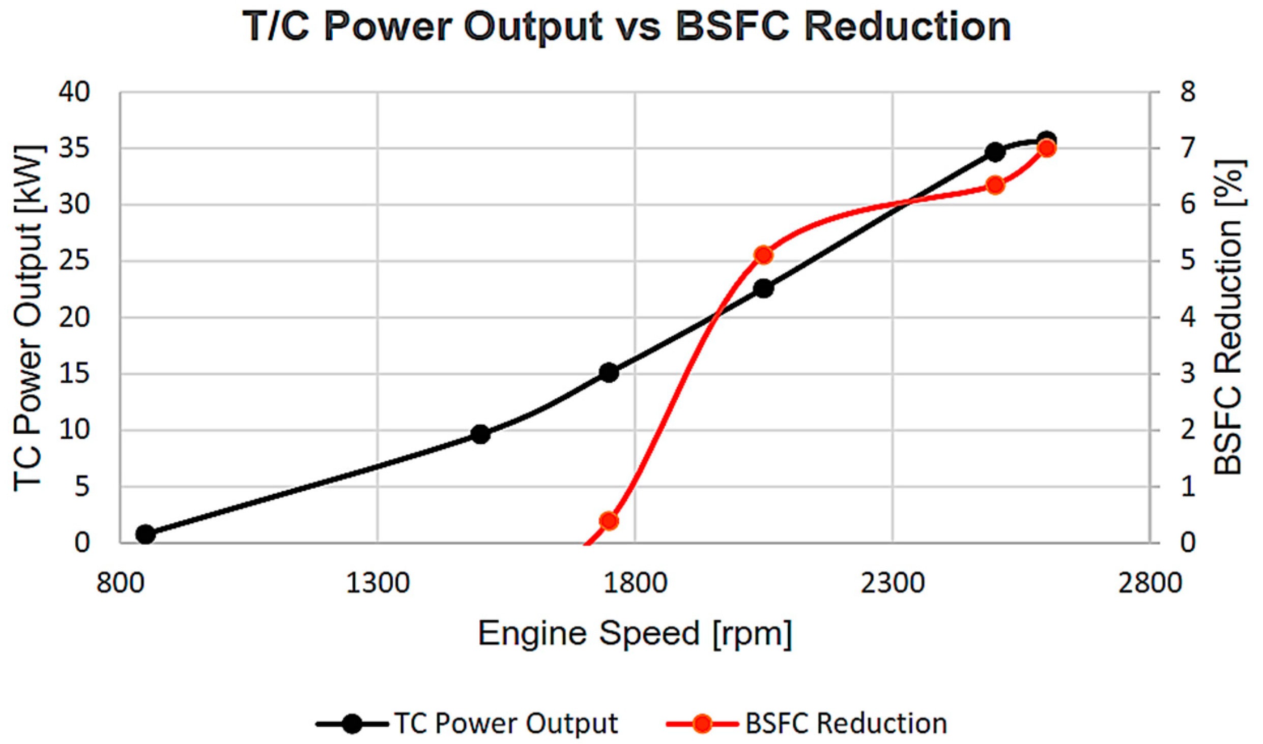
- The power outputs for both WHR methods varied with the systems operational speed. The maximum power obtain by the ORC and T/C systems were 27.3 kW and 35.6 kW respectively.
- The ORC managed a total average BSFC reduction of 4.8%, whereas the T/C yielded an average of 2.3%.
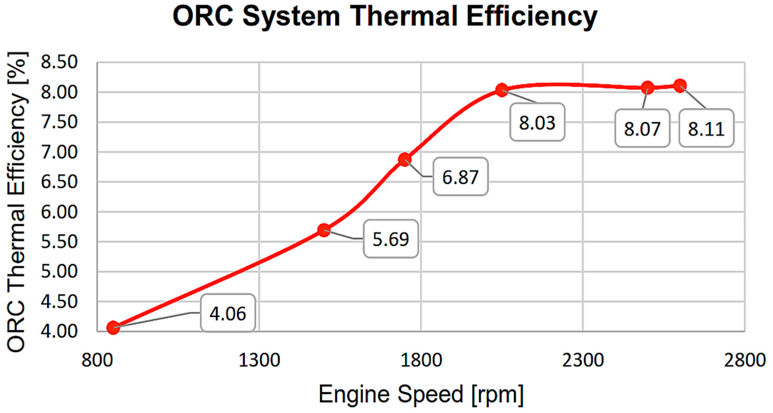
- The thermal efficiencies of the ORC and T/C systems were considerably low, at max values of 8% and 10% respectively.
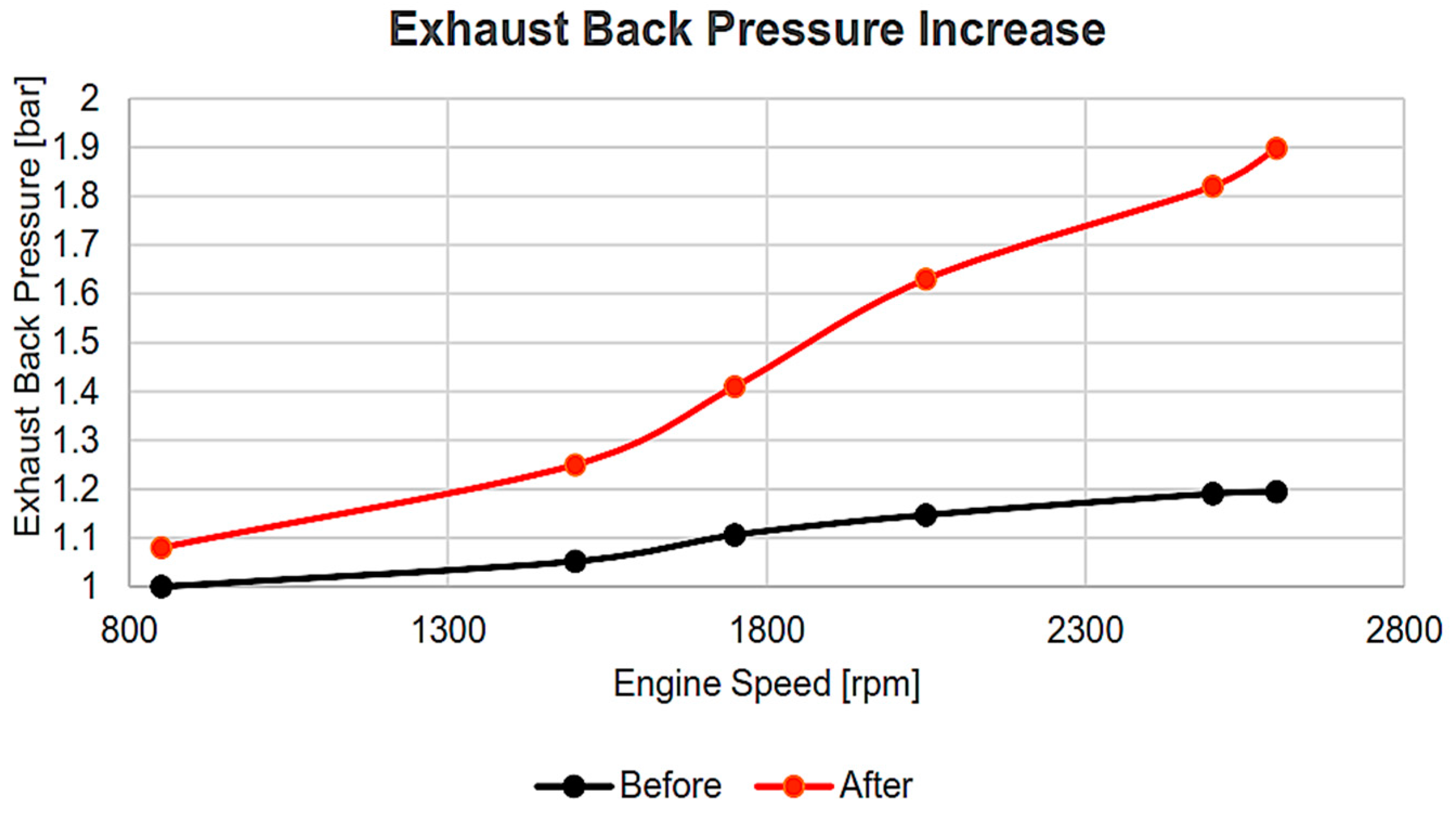
- The raise in exhaust backpressure by the T/C system affected low speed BSFC severely so much so that the system was unable to regenerate enough power to compensate for the additional fuel consumption.
Author Contributions
Funding
Conflicts of Interest
References
- Karvountzis-Kontakiotis, A.; Mahmoudzadeh Andwari, A.; Pesyridis, A.; Russo, S.; Tuccillo, R.; Esfahanian, V. Application of Micro Gas Turbine in Range-Extended Electric Vehicles. Energy 2018, 147, 351–361. [Google Scholar] [CrossRef]
- Shu, G.-Q.; Yu, G.; Tian, H.; Wei, H.; Liang, X. Simulations of a Bottoming Organic Rankine Cycle (ORC) Driven by Waste Heat in a Diesel Engine (DE); SAE International: Warrendale, PA, USA, 2013. [Google Scholar]
- Sprouse, C., III; Depcik, C. Organic Rankine Cycles with Dry Fluids for Small Engine Exhaust Waste Heat Recovery. SAE Int. J. Altern. Powertrains 2013, 2, 96–104. [Google Scholar] [CrossRef]
- Teng, H.; Regner, G.; Cowland, C. Waste Heat Recovery of Heavy-Duty Diesel Engines by Organic Rankine Cycle Part I: Hybrid Energy System of Diesel and Rankine Engines; SAE International: Warrendale, PA, USA, 2007. [Google Scholar]
- Yang, F.; Zhang, H.; Yu, Z.; Wang, E.; Meng, F.; Liu, H.; Wang, J. Parametric optimization and heat transfer analysis of a dual loop ORC (organic Rankine cycle) system for CNG engine waste heat recovery. Energy 2017, 118, 753–775. [Google Scholar] [CrossRef]
- Zhang, X.; Mi, C. Vehicle Power Management; Modeling, Control and Optimization; Springer: London, UK, 2011; p. 346. [Google Scholar]
- Mahmoudzadeh Andwari, A.; Said, M.F.M.; Aziz, A.A.; Esfahanian, V.; Salavati-Zadeh, A.; Idris, M.A.; Perang, M.R.M.; Jamil, H.M. Design, Modeling and Simulation of a High-Pressure Gasoline Direct Injection (GDI) Pump for Small Engine Applications. J. Mech. Eng. 2018, SI 6, 107–120. [Google Scholar]
- Said, M.F.M.; Aziz, A.B.A.; Latiff, Z.A.; Mahmoudzadeh Andwari, A.; Soid, S.N.M. Investigation of Cylinder Deactivation (CDA) Strategies on Part Load Conditions; SAE Technical Paper 2014-01-2549; SAE International: Warrendale, PA, USA, 2014. [Google Scholar]
- Yamaguchi, T.; Aoyagi, Y.; Osada, H.; Shimada, K.; Uchida, N. BSFC Improvement by Diesel-Rankine Combined Cycle in the High EGR Rate and High Boosted Diesel Engine. SAE Int. J. Engines 2013, 6, 1275–1286. [Google Scholar] [CrossRef]
- Yang, Y.; Zhang, H.; Xu, Y.; Zhao, R.; Hou, X.; Liu, Y. Experimental study and performance analysis of a hydraulic diaphragm metering pump used in organic Rankine cycle system. Appl. Therm. Eng. 2018, 132, 605–612. [Google Scholar] [CrossRef]
- Zhang, J.; Zhang, H.; Yang, K.; Yang, F.; Wang, Z.; Zhao, G.; Liu, H.; Wang, E.; Yao, B. Performance analysis of regenerative organic Rankine cycle (RORC) using the pure working fluid and the zeotropic mixture over the whole operating range of a diesel engine. Energy Convers. Manag. 2014, 84, 282–294. [Google Scholar] [CrossRef]
- Zhang, X.; Zeng, K.; Bai, S.; Zhang, Y.; He, M. Exhaust Recovery of Vehicle Gasoline Engine Based on Organic Rankine Cycle; SAE International: Warrendale, PA, USA, 2011. [Google Scholar]
- Zhou, F.; Joshi, S.N.; Rhote-Vaney, R.; Dede, E.M. A review and future application of Rankine Cycle to passenger vehicles for waste heat recovery. Renew. Sustain. Energy Rev. 2017, 75, 1008–1021. [Google Scholar] [CrossRef]
- Bell, C. Maximum Boost: Designing, Testing and Installing Turbocharger Systems; Robert Bentley, Incorporated: Cambridge MA, USA, 1997. [Google Scholar]
- Bin Mamat, A.M.I.; Martinez-Botas, R.F.; Rajoo, S.; Hao, L.; Romagnoli, A. Design methodology of a low pressure turbine for waste heat recovery via electric turbocompounding. Appl. Therm. Eng. 2016, 107, 1166–1182. [Google Scholar] [CrossRef]
- Boretti, A. Improving the Efficiency of Turbocharged Spark Ignition Engines for Passenger Cars through Waste Heat Recovery; SAE International: Warrendale, PA, USA, 2012. [Google Scholar]
- Ghanaati, A.; Said, M.F.M.; Mat Darus, I.Z.; Mahmoudzadeh Andwari, A. A New Approach for Ignition Timing Correction in Spark Ignition Engines Based on Cylinder Tendency to Surface Ignition. Appl. Mech. Mater. 2016, 819, 272–276. [Google Scholar] [CrossRef]
- Mahmoudzadeh Andwari, A.; Aziz, A.A.; Said, M.F.M.; Esfahanian, V.; Latiff, Z.A.; Said, S.N.M. Effect of internal and external EGR on cyclic variability and emissions of a spark ignition two-stroke cycle gasoline engine. J. Mech. Eng. Sci. 2017, 11, 3004–3014. [Google Scholar] [CrossRef]
- Mahmoudzadeh Andwari, A.; Said, M.F.M.; Aziz, A.A.; Esfahanian, V.; Baker, M.R.A.; Perang, M.R.M.; Jamil, H.M. A Study on Gasoline Direct Injection (GDI) Pump System Performance using Model-Based Simulation. J. Soc. Automot. Eng. Malays. 2018, 2, 14–22. [Google Scholar]
- Zhou, L.; Tan, G.; Guo, X.; Chen, M.; Ji, K.; Li, Z.; Yang, Z. Study of Energy Recovery System Based on Organic Rankine Cycle for Hydraulic Retarder; SAE International: Warrendale, PA, USA, 2016. [Google Scholar]
- Arsie, I.; Cricchio, A.; Pianese, C.; Ricciardi, V.; De Cesare, M. Modeling and Optimization of Organic Rankine Cycle for Waste Heat Recovery in Automotive Engines; SAE International: Warrendale, PA, USA, 2016. [Google Scholar]
- Bell, A.G. Forced Induction Performance Tuning; Haynes: Bristol, UK, 2002. [Google Scholar]
- Cipollone, R.; Battista, D.D.; Gualtieri, A. Turbo compound systems to recover energy in ICE. Int. J. Eng. Innov. Technol. 2013, 3, 249–257. [Google Scholar]
- Ghanaati, A.; Mat Darus, I.Z.; Farid, M.; Said, M.; Mahmoudzadeh Andwari, A. A Mean Value Model for Estimation of Laminar and Turbulent Flame Speed in Spark-Ignition Engine. Int. J. Automot. Mech. Eng. Online 2015, 11, 2229–8649. [Google Scholar] [CrossRef]
- Mahmoudzadeh Andwari, A.; Azhar, A.A. Homogenous Charge Compression Ignition (HCCI) Technique: A Review for Application in Two-Stroke Gasoline Engines. Appl. Mech. Mater. 2012, 165, 53–57. [Google Scholar]
- Chen, T.; Zhuge, W.; Zhang, Y.; Zhang, L. A novel cascade organic Rankine cycle (ORC) system for waste heat recovery of truck diesel engines. Energy Convers. Manag. 2017, 138, 210–223. [Google Scholar] [CrossRef]
- Dolz, V.; Novella, R.; García, A.; Sánchez, J. HD Diesel engine equipped with a bottoming Rankine cycle as a waste heat recovery system. Part 1: Study and analysis of the waste heat energy. Appl. Therm. Eng. 2012, 36, 269–278. [Google Scholar] [CrossRef] [Green Version]
- El Chammas, R.; Clodic, D. Combined Cycle for Hybrid Vehicles; SAE International: Warrendale, PA, USA, 2005. [Google Scholar]
- Cochran, D.L. Working Fluids for High Temperature, Rankine Cycle, Space Power Plants; SAE International: Warrendale, PA, USA, 1961. [Google Scholar]
- Mahmoudzadeh Andwari, A.; Pesiridis, A.; Esfahanian, V.; Salavati-Zadeh, A.; Karvountzis-Kontakiotis, A.; Muralidharan, V. A Comparative Study of the Effect of Turbocompounding and ORC Waste Heat Recovery Systems on the Performance of a Turbocharged Heavy-Duty Diesel Engine. Energies 2017, 10, 1087. [Google Scholar] [CrossRef]
- Ringler, J.; Seifert, M.; Guyotot, V.; Hübner, W. Rankine Cycle for Waste Heat Recovery of IC Engines. SAE Int. J. Engines 2009, 2, 67–76. [Google Scholar] [CrossRef]
- Serrano, J.R.; Dolz, V.; Novella, R.; García, A. HD Diesel engine equipped with a bottoming Rankine cycle as a waste heat recovery system. Part 2: Evaluation of alternative solutions. Appl. Therm. Eng. 2012, 36, 279–287. [Google Scholar] [CrossRef] [Green Version]
- Lodwig, E. Performance of a 35 HP Organic Rankine Cycle Exhaust Gas Powered System; SAE International: Warrendale, PA, USA, 1970. [Google Scholar]
- Mahmoudzadeh Andwari, A.; Pesyridis, A.; Esfahanian, V.; Said, M.F.M. Combustion and Emission Enhancement of a Spark Ignition Two-Stroke Cycle Engine Utilizing Internal and External Exhaust Gas Recirculation Approach at Low-Load Operation. Energies 2019, 12, 609. [Google Scholar] [CrossRef]
- Matthew Read, I.S. Nikola Stosic and Ahmed Kovacevic, Comparison of Organic Rankine Cycle Systems under Varying Conditions Using Turbine and Twin-Screw Expanders. Energies 2016, 9, 614. [Google Scholar] [CrossRef]
- Mavrou, P.; Papadopoulos, A.I.; Seferlis, P.; Linke, P.; Voutetakis, S. Selection of working fluid mixtures for flexible Organic Rankine Cycles under operating variability through a systematic nonlinear sensitivity analysis approach. Appl. Therm. Eng. 2015, 89, 1054–1067. [Google Scholar] [CrossRef]
- Allouache, A.; Leggett, S.; Hall, M.J.; Tu, M.; Baker, C.; Fateh, H. Simulation of Organic Rankine Cycle Power Generation with Exhaust Heat Recovery from a 15 liter Diesel Engine. SAE Int. J. Mater. Manf. 2015, 8, 227–238. [Google Scholar] [CrossRef]
- Çengel, Y.A. Introduction to Thermodynamics and Heat Transfer; McGraw-Hill: New York, NY, USA, 2007. [Google Scholar]
- Mahmoudzadeh Andwari, A.; Aziz, A.A.; Muhamad Said, M.F.; Abdul Latiff, Z. Controlled Auto-Ignition Combustion in a Two-Stroke Cycle Engine Using Hot Burned Gases. Appl. Mech. Mater. 2013, 388, 201–205. [Google Scholar] [CrossRef]
- Pesiridis, A. Automotive Exhaust Emissions and Energy Recovery; Nova Science Publishers, Incorporated: Hauppauge, NY, USA, 2014. [Google Scholar]
- Mahmoudzadeh Andwari, A.; Pesiridis, A.; Karvountzis-Kontakiotis, A.; Esfahanian, V. Hybrid electric vehicle performance with organic rankine cycle waste heat recovery system. Appl. Sci. 2017, 7, 437. [Google Scholar] [CrossRef]
- Shu, G.; Zhao, J.; Tian, H.; Wei, H.; Liang, X.; Yu, G.; Liu, L. Theoretical Analysis of Engine Waste Heat Recovery by the Combined Thermo-Generator and Organic Rankine Cycle System; SAE International: Warrendale, PA, USA, 2012. [Google Scholar]
- Tennant, D.W.H.; Walsham, B.E. The Turbocompound Diesel Engine; SAE International: Warrendale, PA, USA, 1989. [Google Scholar]
- Wang, E.; Yu, Z.; Zhang, H.; Yang, F. A regenerative supercritical-subcritical dual-loop organic Rankine cycle system for energy recovery from the waste heat of internal combustion engines. Appl. Energy 2017, 190, 574–590. [Google Scholar] [CrossRef]
- Wilson, D.E. The Design of a Low Specific Fuel Consumption Turbocompound Engine; SAE International: Warrendale, PA, USA, 1986. [Google Scholar]
- Mahmoudzadeh Andwari, A.; Aziz, A.A.; Said, M.F.M.; Latiff, Z.A. A Converted Two-Stroke Cycle Engine for Compression Ignition Combustion. Appl. Mech. Mater. 2014, 663, 331–335. [Google Scholar] [CrossRef]
- Kolasiński, P.; Błasiak, P.; Rak, J. Experimental and Numerical Analyses on the Rotary Vane Expander Operating Conditions in a Micro Organic Rankine Cycle System. Energies 2016, 9, 606. [Google Scholar] [CrossRef]
- Quoilin, S.; Broek, M.V.D.; Declaye, S.; Dewallef, P.; Lemort, V. Techno-economic survey of Organic Rankine Cycle (ORC) systems. Renew. Sustain. Energy Rev. 2013, 22, 168–186. [Google Scholar] [CrossRef] [Green Version]
- Katsanos, C.O.; Hountalas, D.T.; Pariotis, E.G. Thermodynamic analysis of a Rankine cycle applied on a diesel truck engine using steam and organic medium. Energy Convers. Manag. 2012, 60, 68–76. [Google Scholar] [CrossRef]
- Kölsch, B.; Radulovic, J. Utilisation of diesel engine waste heat by Organic Rankine Cycle. Appl. Therm. Eng. 2015, 78, 437–448. [Google Scholar] [CrossRef] [Green Version]
- Kulkarni, K.; Sood, A. Performance Analysis of Organic Rankine Cycle (ORC) for Recovering Waste Heat from a Heavy Duty Diesel Engine; SAE International: Warrendale, PA, USA, 2015. [Google Scholar]
- Kunte, H.; Seume, J. Partial Admission Impulse Turbine for Automotive ORC Application; SAE International: Warrendale, PA, USA, 2013. [Google Scholar]
- Lion, S.; Michos, C.N.; Vlaskos, I.; Rouaud, C.; Taccani, R. A review of waste heat recovery and Organic Rankine Cycles (ORC) in on-off highway vehicle Heavy Duty Diesel Engine applications. Renew. Sustain. Energy Rev. 2017, 79, 691–708. [Google Scholar] [CrossRef]
- Mahmoudzadeh Andwari, A.; Aziz, A.A.; Said, M.F.M.; Latiff, Z.A.; Ghanaati, A. Influence of Hot Burned Gas Utilization on the Exhaust Emission Characteristics of a Controlled Auto-Ignition Two-Stroke Cycle Engine. Int. J. Automot. Mech. Eng. Online 2015, 11, 2229–8649. [Google Scholar]
- Hopmann, U.; Algrain, M.C. Diesel Engine Electric Turbo Compound Technology; SAE International: Warrendale, PA, USA, 2003. [Google Scholar]
- Heywood, J.B. Internal Combustion Engine Fundamentals; McGraw-Hill: New York, NY, USA, 1988. [Google Scholar]
- Nicolas Stanzel, T.S. Markus Preißinger and Dieter Brüggemann, Comparison of Cooling System Designs for an Exhaust Heat Recovery System Using an Organic Rankine Cycle on a Heavy Duty Truck. Energies 2016, 9, 928. [Google Scholar] [CrossRef]
- Karvountzis-Kontakiotis, A.; Pesiridis, A.; Zhao, H.; Alshammari, F.; Franchetti, B.; Pesmazoglou, I.; Tocci, L. Effect of an ORC Waste Heat Recovery System on Diesel Engine Fuel Economy for Off-Highway Vehicles; SAE International: Warrendale, PA, USA, 2017. [Google Scholar]
- Jadhao, J.S.; Thombare, D.G. Review on Exhaust Gas Heat Recovery for I.C Engine. Int. J. Eng. Innov. Technol. 2013, 2, 93–100. [Google Scholar]
- Hountalas, D.T.; Katsanos, C.O.; Lamaris, V.T. Recovering Energy from the Diesel Engine Exhaust Using Mechanical and Electrical Turbocompounding; SAE International: Warrendale, PA, USA, 2007. [Google Scholar]
- He, S.; Chang, H.; Zhang, X.; Shu, S.; Duan, C. Working fluid selection for an Organic Rankine Cycle utilizing high and low temperature energy of an LNG engine. Appl. Therm. Eng. 2015, 90, 579–589. [Google Scholar] [CrossRef]
- Noora, A.M.; Putehc, R.C.; Martinez-Botasd, R.; Rajooa, S.; Romagnolie, A.; Basheera, U.M.; Sallehb, S.H.S.; Saha, M.H.M. Technologies for Waste Heat Energy Recovery from Internal Combustion Engine: A Review. In Proceedings of the International Conference on New Trends in Multidisciplinary Research & Practice, Istanbul, Turkey, 4–5 November 2015. [Google Scholar]
- Hsieh, J.-C.; Fu, B.-R.; Wang, T.-W.; Cheng, Y.; Lee, Y.-R.; Chang, J.-C. Design and preliminary results of a 20-kW transcritical organic Rankine cycle with a screw expander for low-grade waste heat recovery. Appl. Therm. Eng. 2017, 110, 1120–1127. [Google Scholar] [CrossRef]
- Shu, G.; Wang, X.; Tian, H. Theoretical analysis and comparison of rankine cycle and different organic rankine cycles as waste heat recovery system for a large gaseous fuel internal combustion engine. Appl. Therm. Eng. 2016, 108, 525–537. [Google Scholar] [CrossRef]
- Reck, M.; Randolf, D. An Organic Rankine Cycle Engine for a 25-Passenger Bus; SAE International: Warrendale, PA, USA, 1973. [Google Scholar]
- Markides, O.A.; Markides, C.N. Thermo-Economic and Heat Transfer Optimization of Working-Fluid Mixtures in a Low-Temperature Organic Rankine Cycle System. Energies 2016, 9, 448. [Google Scholar] [Green Version]
- Brands, M.C.; Werner, J.R.; Hoehne, J.L.; Kramer, S. Vechicle Testing of Cummins Turbocompound Diesel Engine; SAE International: Warrendale, PA, USA, 1981. [Google Scholar]
- Alshammari, F.; Pesyridis, A.; Karvountzis-Kontakiotis, A.; Franchetti, B.; Pesmazoglou, I. Experimental Study of a Small Scale Organic Rankine Cycle Waste Heat Recovery System for a Heavy Duty Diesel Engine with Focus on the Radial Inflow Turbine Expander Performance. Appl. Energy 2018, 215, 543–555. [Google Scholar] [CrossRef]


| Specification | Value |
|---|---|
| Engine Type | In-line 6, 4-Stroke, Diesel CI, Common Rail |
| Bore × Stroke | 130 × 144 (mm) |
| Displacement | 11.5 (L) |
| Compression Ratio | 19:1 |
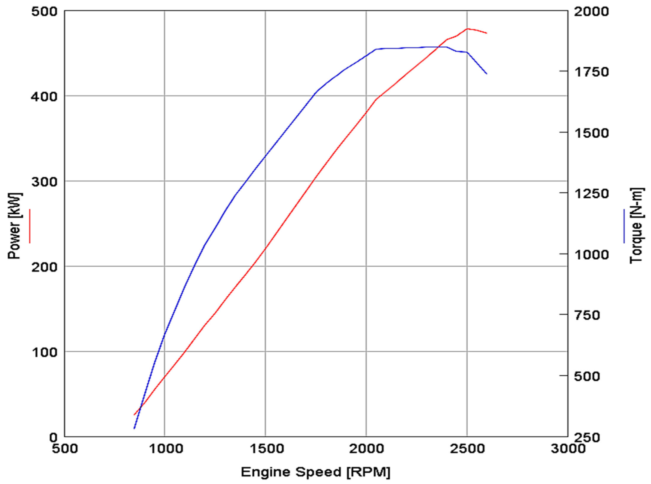
| Max Power | 478.3 [kW] @ 2500 RPM |
| Max Torque | 1850 [N·m] @ 2050 RPM |
| BSFC at Peak Efficiency | 214.7 [g/kW·h] |
| RPM Range | 850–2600 |
| ORC’s Main Components | ||||||
|---|---|---|---|---|---|---|
| Design Parameters | Evaporator (Exhaust) | Evaporator (Organic Fluid) | Condenser (Coolant) | Condenser (Organic Fluid) | Turbine Expander | Pump |
| Average Inlet Pressure (bar) | 1.00102 | 24.9 | 2.15 | 3.28 | 24.3 | 2.6 |
| Average Outlet Pressure (bar) | 1 | 24.3 | 2 | 2.6 | 3.28 | 24.9 |
| Average Pressure Drop (bar) | 0.0010197 | 0.631 | 0.148264 | 0.674932 | - | - |
| Average Inlet Temperature (K) | 973.1 | 315.8 | 296.1 | 405.1 | 445.2 | 314.1 |
| Average Outlet Temperature (K) | 450.7 | 445.2 | 302.6 | 314.1 | 405.263 | 315.8 |
| Average Mass Flow Rate (g/s) | 140 | 269.2 | 3394.6 | 269.3 | 0.269 | 0.269 |
| Combined Energy Rate out of Fluid (kW) | 78.7 | −78.7 | −73.2 | 73.2 | - | - |
| Average Map Pressure Ratio | - | - | - | - | 7.37 | - |
| Average Efficiency (%) | - | - | - | - | 51.61 | 61.42 |
| Average Power (kW) | - | - | - | - | 5.3 | 0.75 |
| Average Pressure Rise (bar) | - | - | - | - | - | 22.3 |
| X1 | X2 | X3 | ||||
| Speed | Pump | Turbine | Pump | Turbine | Pump | Turbine |
| 1500 | 0.146 | 0.894 | 0.328 | 5.112 | 0.456 | 8.631 |
| 1750 | 0.170 | 1.244 | 0.415 | 7.745 | 0.482 | 11.976 |
| 2000 | 0.182 | 1.152 | 0.596 | 9.339 | 0.543 | 12.104 |
| 2250 | 0.210 | 0.783 | 0.678 | 8.497 | 0.608 | 14.536 |
| 2500 | 0.256 | 0.490 | 0.828 | 6.723 | 0.693 | 12.863 |
| X4 | X5 | X6 | ||||
| Speed | Pump | Turbine | Pump | Turbine | Pump | Turbine |
| 1500 | 0.443 | 10.710 | 0.514 | 13.211 | 0.553 | 12.479 |
| 1750 | 0.510 | 14.641 | 0.534 | 16.483 | 0.588 | 17.217 |
| 2000 | 0.593 | 18.040 | 0.594 | 23.712 | 0.624 | 20.687 |
| 2250 | 0.628 | 21.843 | 0.626 | 28.225 | 0.676 | 28.749 |
| 2500 | 0.770 | 18.740 | 0.760 | 22.686 | 0.870 | 27.081 |
| Point | BSFC Reduction (%) |
|---|---|
| X1 | 4.64 |
| X2 | 3.83 |
| X3 | 4.36 |
| X4 | 5.11 |
| X5 | 5.16 |
| X6 | 5.6 |
| Total | 4.78 |
| Turbine Speed (rpm) | Idle (kW) | Ideal BSFC (kW) | Part Load (kW) | Max Torque (kW) | Max Power (kW) | Max Speed (kW) |
|---|---|---|---|---|---|---|
| 20,000 | 0.530 | 7.409 | 10.265 | 15.874 | 20.762 | 21.520 |
| 30,000 | 0.530 | 7.964 | 12.480 | 16.933 | 21.635 | 23.719 |
| 40,000 | 0.564 | 8.537 | 13.683 | 17.452 | 22.451 | 26.148 |
| 50,000 | 0.544 | 9.426 | 14.973 | 18.638 | 25.976 | 27.452 |
| 60,000 | 0.598 | 10.648 | 15.126 | 19.747 | 27.160 | 29.897 |
| 70,000 | 0.756 | 10.156 | 15.033 | 21.805 | 28.799 | 31.211 |
| 80,000 | 0.784 | 9.754 | 14.770 | 22.587 | 30.425 | 32.146 |
| 90,000 | 0.874 | 8.647 | 13.589 | 21.770 | 33.916 | 34.524 |
| 100,000 | 0.897 | 8.504 | 12.981 | 20.836 | 34.667 | 35.686 |
| 110,000 | 0.904 | 7.468 | 11.627 | 20.620 | 34.037 | 34.827 |
| 120,000 | 0.765 | 6.832 | 10.725 | 18.869 | 31.042 | 32.684 |
| Engine Speed (rpm) | BSFC Increase (%) |
|---|---|
| 850 | 6.864001 |
| 1500 | 5.270832 |
| 1750 | 4.345699 |
| 2050 | 0.554805 |
| 2500 | 0.468826 |
| 2600 | 0.536313 |
| Total | 3 |
| Operational Point | BSFC Reduction (%) |
|---|---|
| X1 | −4.02734 |
| X2 | −1.08217 |
| X3 | 0.392548 |
| X4 | 5.113118 |
| X5 | 6.355747 |
| X6 | 7.011852 |
| Total | 2.293959167 |
© 2019 by the authors. Licensee MDPI, Basel, Switzerland. This article is an open access article distributed under the terms and conditions of the Creative Commons Attribution (CC BY) license (http://creativecommons.org/licenses/by/4.0/).
Share and Cite
Mahmoudzadeh Andwari, A.; Pesyridis, A.; Esfahanian, V.; Salavati-Zadeh, A.; Hajialimohammadi, A. Modelling and Evaluation of Waste Heat Recovery Systems in the Case of a Heavy-Duty Diesel Engine. Energies 2019, 12, 1397. https://doi.org/10.3390/en12071397
Mahmoudzadeh Andwari A, Pesyridis A, Esfahanian V, Salavati-Zadeh A, Hajialimohammadi A. Modelling and Evaluation of Waste Heat Recovery Systems in the Case of a Heavy-Duty Diesel Engine. Energies. 2019; 12(7):1397. https://doi.org/10.3390/en12071397
Chicago/Turabian StyleMahmoudzadeh Andwari, Amin, Apostolos Pesyridis, Vahid Esfahanian, Ali Salavati-Zadeh, and Alireza Hajialimohammadi. 2019. "Modelling and Evaluation of Waste Heat Recovery Systems in the Case of a Heavy-Duty Diesel Engine" Energies 12, no. 7: 1397. https://doi.org/10.3390/en12071397
APA StyleMahmoudzadeh Andwari, A., Pesyridis, A., Esfahanian, V., Salavati-Zadeh, A., & Hajialimohammadi, A. (2019). Modelling and Evaluation of Waste Heat Recovery Systems in the Case of a Heavy-Duty Diesel Engine. Energies, 12(7), 1397. https://doi.org/10.3390/en12071397