Pipe Sizing for Novel Heat Distribution Technology


Abstract
:1. Introduction
- What is the assessed specific heat loss for different twin-pipe and triple-pipe configurations?
- What are the assessed differential pressure requirements for different pipe configurations, expressed in terms of pressure head and specific values for the third pipe in the proposed distribution technology?
- What are the feasible design criteria for sizing the third pipe with respect to heat loss, annual pump energy demands, and the space within the casing?
2. Methods
2.1. Simulation Model Summary
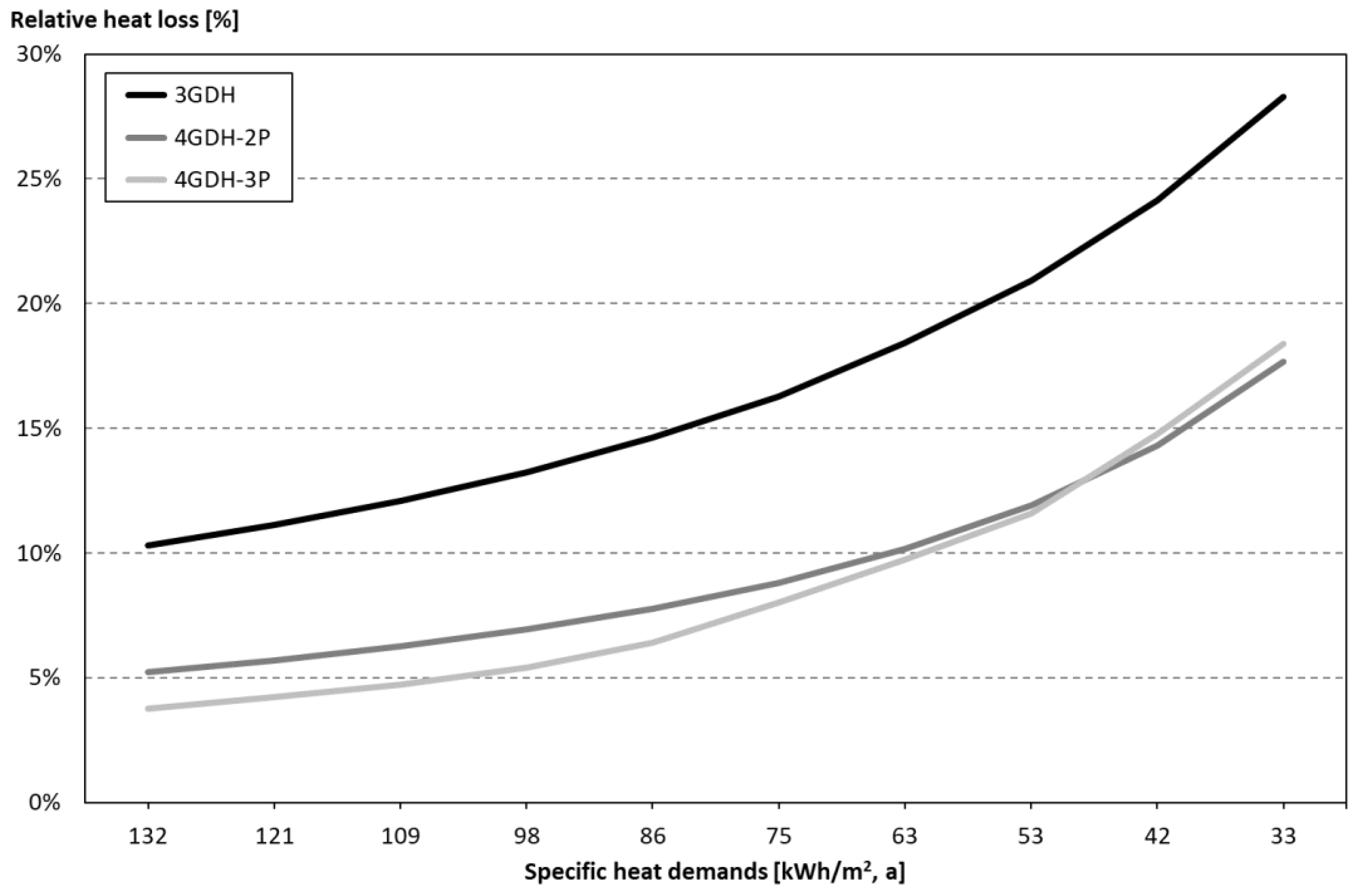
2.2. Specific Heat Loss Assessment
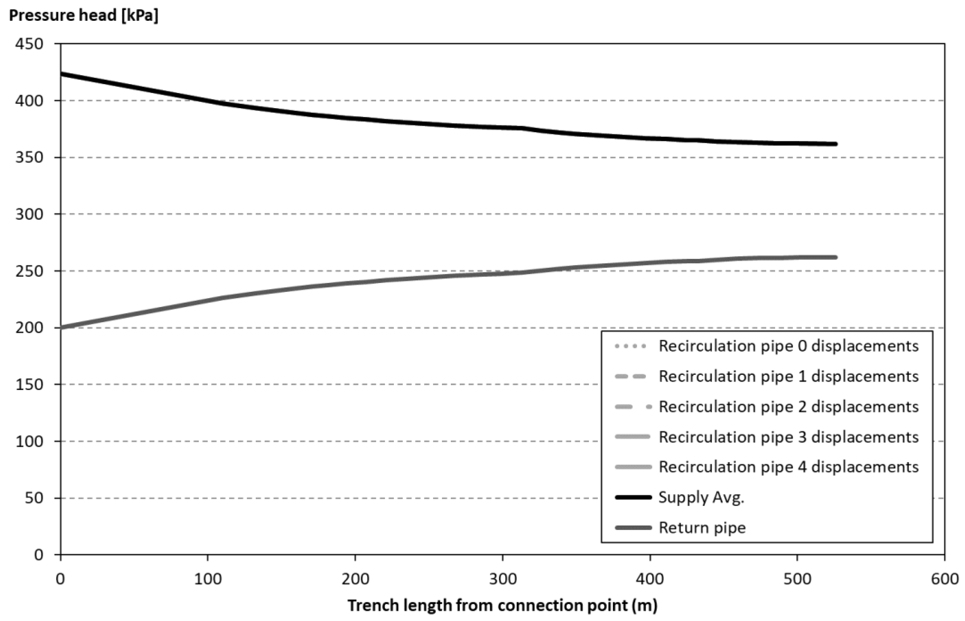
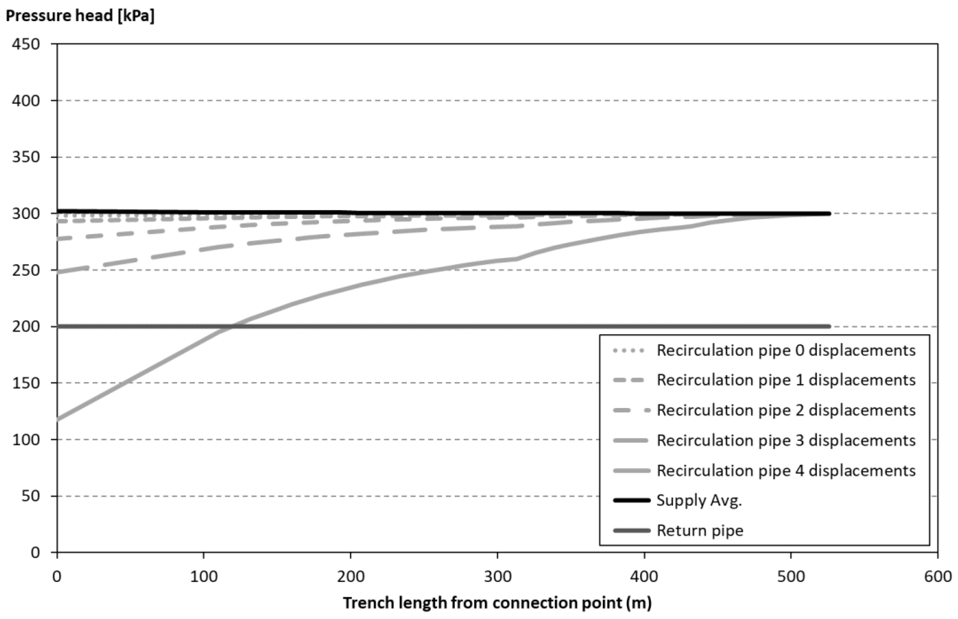
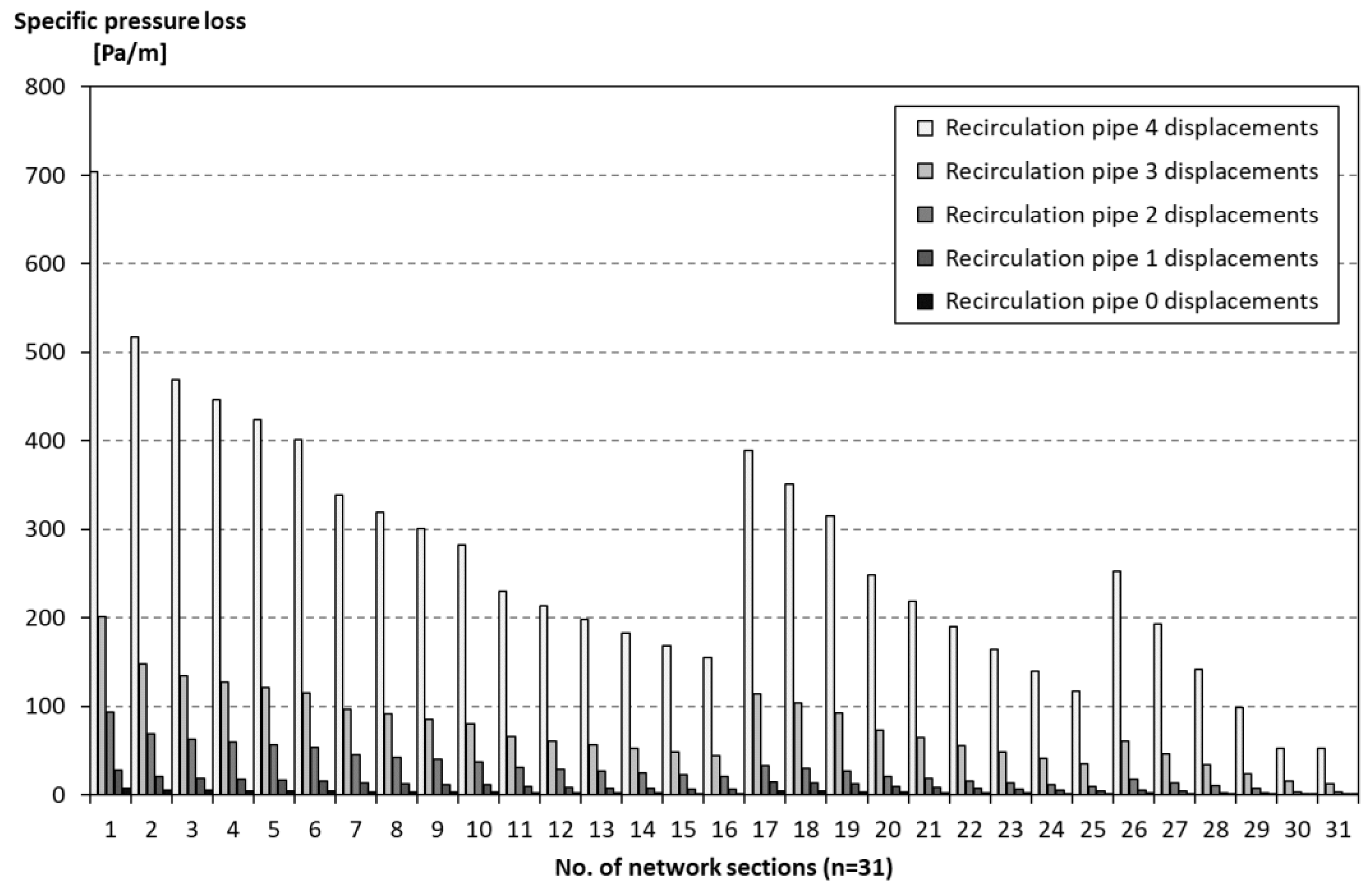
2.3. Pressure Loss Assessment
2.4. Sizing of the Third Pipe
3. Results
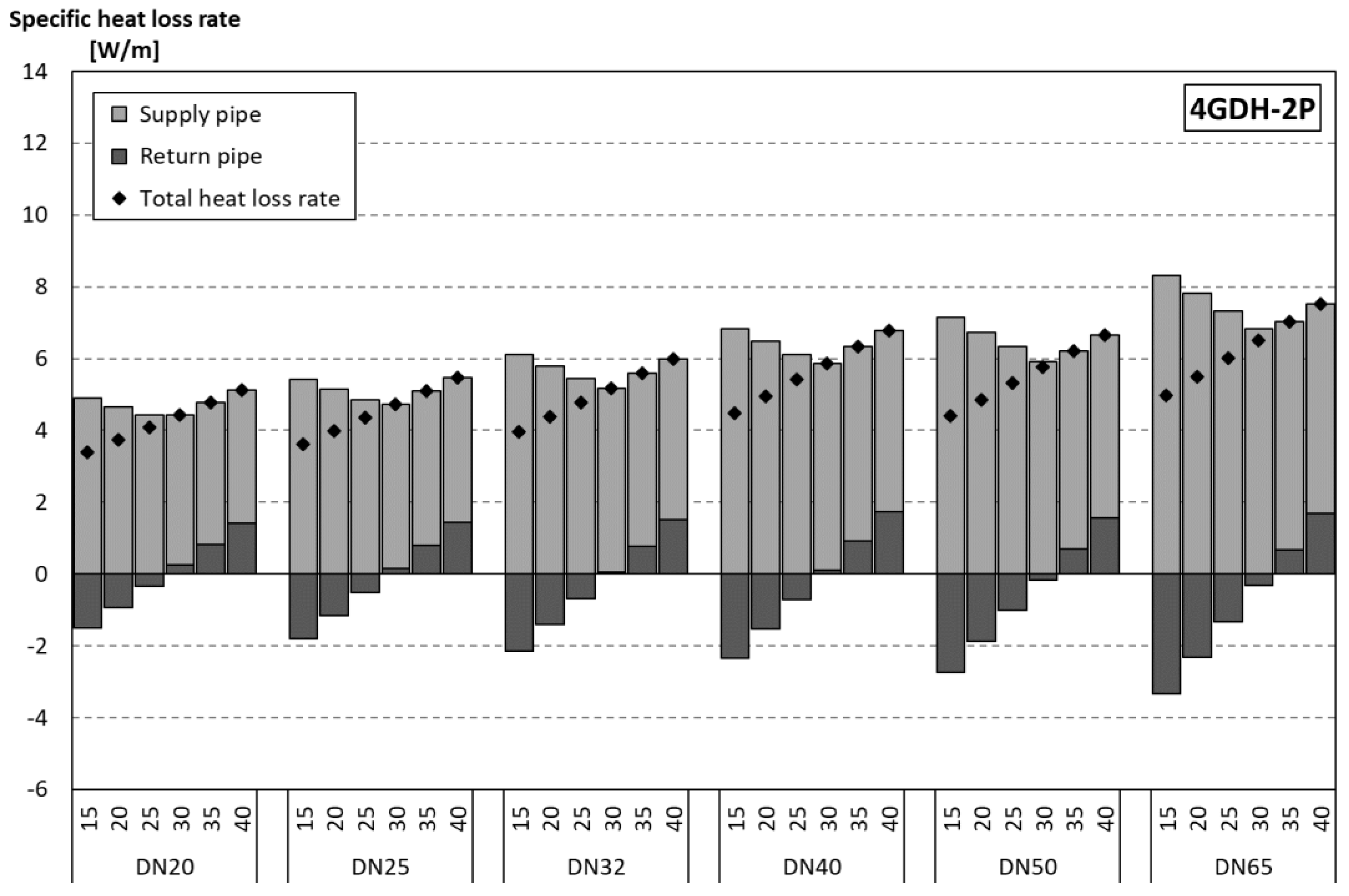
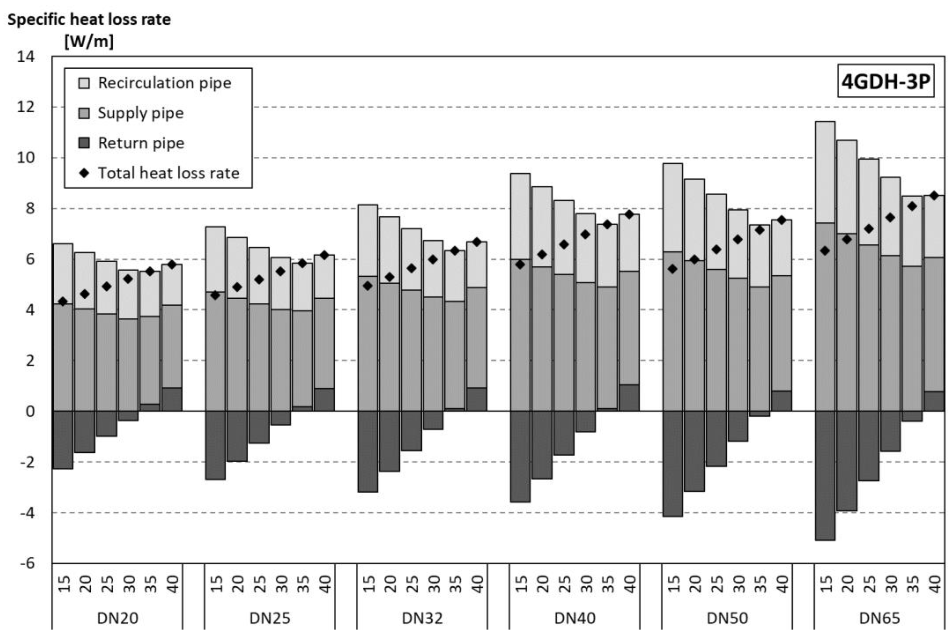
3.1. Specific Heat Loss Assessment
3.2. Pressure Loss Assessment
3.3. Size of the Third Pipe
3.3.1. Size of the Third Pipe: Heat Loss
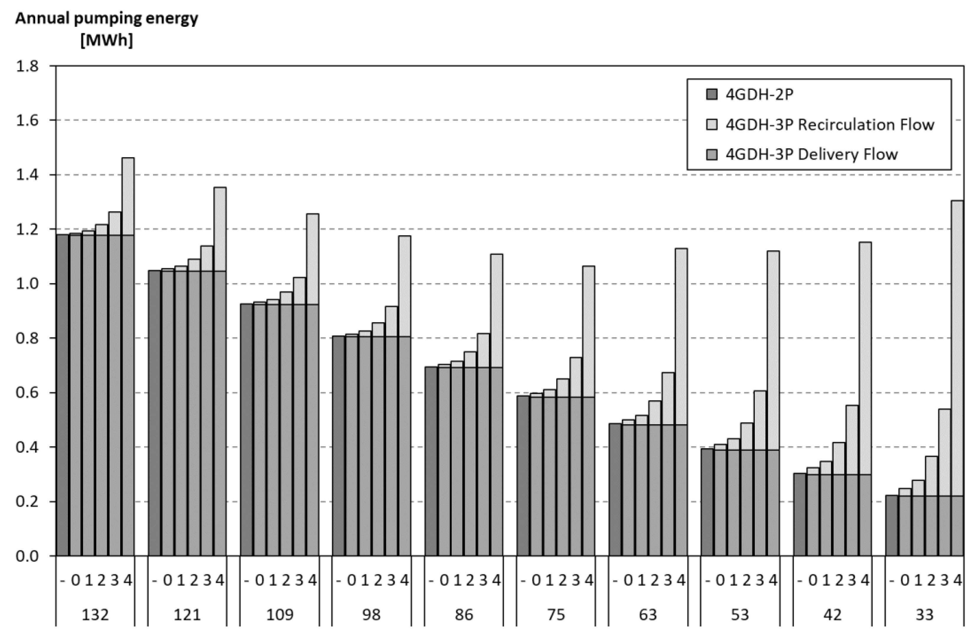
3.3.2. Size of the Third Pipe: Pumping Energy
3.3.3. Size of the Third Pipe: Space within Casing
4. Discussion
5. Conclusions
Author Contributions
Funding
Acknowledgments
Conflicts of Interest
References
- Gong, M.; Werner, S. Exergy analysis of network temperature levels in Swedish and Danish district heating systems. Renew. Energy 2015, 84, 106–113. [Google Scholar]
- Frederiksen, S.; Werner, S. District Heating and Cooling; Studentlitteratur AB: Lund, Sweden, 2013. [Google Scholar]
- Werner, S. International review of district heating and cooling. Energy 2017, 137 (Suppl. C), 617–631. [Google Scholar] [CrossRef]
- Persson, U.; Werner, S. Heat distribution and the future competitiveness of district heating. Appl. Energy 2011, 88, 568–576. [Google Scholar] [CrossRef]
- Connolly, D.; Lund, H.; Mathiesen, B.V.; Werner, S.; Möller, B.; Persson, U.; Boermans, T.; Trier, D.; Østergaard, P.A.; Nielsen, S. Heat Roadmap Europe: Combining district heating with heat savings to decarbonise the EU energy system. Energy Policy 2014, 65, 475–489. [Google Scholar] [CrossRef]
- Directive 2010/31/EU of the European Parliament and of the Council of 19 May 2010 on the Energy Performance of Buildings; [2010] OJ L153/13; European Parliament: Strasbourg, France; Council of the European Union: Brussels, Belgium, 2010.
- Directive 2012/27/EU, Directive 2012/27/EU of the European Parliament and of the Council of 25 October 2012 on Energy Efficiency Amending Directives 2009/125/EC and 2010/30/EU and Repealing Directives 2004/8/EC and 2006/32/EC; [2012] OJ L315/1; European Parliament: Strasbourg, France; Council of the European Union: Brussels, Belgium, 2012.
- Lund, H.; Werner, S.; Wiltshire, R.; Svendsen, S.; Thorsen, J.E.; Hvelplund, F.; Mathiesen, B.V. 4th Generation District Heating (4GDH): Integrating smart thermal grids into future sustainable energy systems. Energy 2014, 68, 1–11. [Google Scholar] [CrossRef]
- Lund, H.; Østergaard, P.A.; Chang, M.; Werner, S.; Svendsen, S.; Sorknæs, P.; Thorsen, J.E.; Hvelplund, F.; Mortensen, B.O.G.; Mathiesen, B.V.; et al. The status of 4th generation district heating: Research and results. Energy 2018, 164, 147–159. [Google Scholar] [CrossRef]
- Averfalk, H.; Werner, S. Novel low temperature heat distribution technology. Energy 2018, 145, 526–539. [Google Scholar] [CrossRef]
- Wallentén, P. Steady-State Heat Loss From Insulated Pipes; Licentiate Thesis, Report TVBH-3017; Dept. of Building Physics, Lund Institute of Technology: Lund, Sweden, 1991. [Google Scholar]
- European Committee for Standardiztion (CEN). District Heating Pipes—Preinsulated Bonded Twin Pipe Systems for Directly Buried Hot Water Networks—Part 1: Twin Pipe Assembly of Steel Service Pipe, Polyurethane Thermal Insulation and Outer Casing of Polyethylene; European Standard EN 15698-1:2009; European Committee for Standardiztion: Brussels, Belgium, 2009. [Google Scholar]
- Bennet, J.; Claesson, J.; Hellström, G. Multipole Method to Compute The Conductive Heat Flows to and between Pipes in a Composite Cylinder; Lund University: Lund, Sweden, 1987. [Google Scholar]
- Claesson, J.; Hellström, G. Multipole method to calculate borehole thermal resistances in a borehole heat exchanger. HVAC R Res. 2011, 17, 895–911. [Google Scholar]
- Javed, S.; Claesson, J. Second-order multipole formulas for thermal resistance of single U-tube borehole heat exchangers. In Proceedings of the IGSHPA Technical/Research Conference and Expo, Denver, CO, USA, 14–16 March 2017. [Google Scholar]
- European Committee for Standardiztion (CEN). District Heating Pipes—Preinsulated Bonded Pipe Systems for Directly Buried Hot Water Networks—Pipe Assembly of Steel Service Pipe, Polyurethane Thermal Insulation and Outer Casing of Polyethylene; European Standard EN 253:2009+A2:2015; European Committee for Standardiztion: Brussels, Belgium, 2015. [Google Scholar]
- European Committee for Standardiztion (CEN). Seamless and Welded Steel Tubes—Dimensions and Masses Per Unit Length; European Standard EN 10220; European Committee for Standardiztion: Brussels, Belgium, 2002. [Google Scholar]
- Bøhm, B.; Kristjansson, H. Single, twin and triple buried heating pipes: On potential savings in heat losses and costs. Int. J. Energy Res. 2005, 29, 1301–1312. [Google Scholar] [CrossRef]
- Powerpipe, Product Catalogue, 2016 ed.; Powerpipe Systems AB: Gothenburg, Sweden, 2016.
- Koiv, T.-A.; Mikola, A.; Palmiste, U. The new dimensioning method of the district heating network. Appl. Therm. Eng. 2014, 71, 78–82. [Google Scholar] [CrossRef]
- Dalla Rosa, A.; Li, H.; Svendsen, S. Method for optimal design of pipes for low-energy district heating, with focus on heat losses. Energy 2011, 36, 2407–2418. [Google Scholar] [CrossRef]
- Brand, L.; Calvén, A.; Englund, J.; Landersjö, H.; Lauenburg, P. Smart district heating networks—A simulation study of prosumers’ impact on technical parameters in distribution networks. Appl. Energy 2014, 129, 39–48. [Google Scholar] [CrossRef]
- Brange, L.; Englund, J.; Lauenburg, P. Prosumers in district heating networks—A Swedish case study. Appl. Energy 2016, 164, 492–500. [Google Scholar] [CrossRef]


| Pipe | 4GDH-2P | 4GDH-3P |
|---|---|---|
| Flow Rates | Flow Rates | |
| Supply (first pipe) | Delivery and recirculation flows (combined) | Delivery and recirculation flows (combined) |
| Return (second pipe) | Delivery and recirculation flows (combined) | Delivery flow (separated) |
| Third (third pipe) | No third pipe | Recirculation flow (separated) |
| Label | Unit | 0 | 1 | 2 | 3 | 4 |
|---|---|---|---|---|---|---|
| Differential pressure, Δp | kPa | 2 | 7 | 22 | 52 | 182 |
| Pumping power | W | 2 | 8 | 26 | 60 | 212 |
© 2019 by the authors. Licensee MDPI, Basel, Switzerland. This article is an open access article distributed under the terms and conditions of the Creative Commons Attribution (CC BY) license (http://creativecommons.org/licenses/by/4.0/).
Share and Cite
Averfalk, H.; Ottermo, F.; Werner, S. Pipe Sizing for Novel Heat Distribution Technology. Energies 2019, 12, 1276. https://doi.org/10.3390/en12071276
Averfalk H, Ottermo F, Werner S. Pipe Sizing for Novel Heat Distribution Technology. Energies. 2019; 12(7):1276. https://doi.org/10.3390/en12071276
Chicago/Turabian StyleAverfalk, Helge, Fredric Ottermo, and Sven Werner. 2019. "Pipe Sizing for Novel Heat Distribution Technology" Energies 12, no. 7: 1276. https://doi.org/10.3390/en12071276
APA StyleAverfalk, H., Ottermo, F., & Werner, S. (2019). Pipe Sizing for Novel Heat Distribution Technology. Energies, 12(7), 1276. https://doi.org/10.3390/en12071276