Article

Thermodynamics and Kinetics of CO2/CH4 Adsorption on Shale from China: Measurements and Modeling

Key Laboratory of Ocean Energy Utilization and Energy Conservation of Ministry of Education, School of Energy and Power Engineering, Dalian University of Technology, Dalian 116024, China
*
Author to whom correspondence should be addressed.
Energies 2019, 12(6), 978; https://doi.org/10.3390/en12060978
Submission received: 8 January 2019 / Revised: 7 March 2019 / Accepted: 8 March 2019 / Published: 13 March 2019

Abstract

:
CO2-enhanced shale gas recovery (CO2-ESGR) sequestrates anthropogenic CO2 and improves the profitability of shale gas exploitation. This work investigated the adsorption behaviors of CO2 and CH4 on shale from China at 20, 40, 60 and 80 °C. The pressure ranges for CO2 and CH4 were 1–5 and 1–15 MPa, respectively. The excess adsorbed amount of CH4 increased with increasing pressure from the beginning to the end, while the maximum excess CO2 adsorption was observed at approximately 4 MPa. The absolute average deviations (AADs) of CO2 and CH4, determined by the Langmuir + k model, were 2.12–3.10% and 0.88–1.11%, respectively. Relatively good adsorptivity for CO2 was exhibited when the pressure was less than 5 MPa, which was beneficial to the implementation of CO2-ESGR. With continuous increases in pressure, the adsorption capacity of CO2 was weaker than that of CH4, suggesting that the injected CO2 would reduce the partial pressure of CH4 for CO2-ESGR and the displacement effect would no longer be significant. In addition, the adsorption rate of CO2 was much faster than that of CH4. CO2 was more active in the competitive adsorption and it was advantageous to the efficiency of CO2-ESGR.

Graphical Abstract

1. Introduction

Carbon capture, utilization, and storage (CCUS) has exhibited great potential in reducing the concentration of atmospheric CO2, and has played an indispensable role in mitigating the severe consequences of global warming [1,2,3,4,5,6,7,8]. CO2-enhanced shale gas recovery (CO2-ESGR) not only creates the opportunity for sequestrating anthropogenic CO2, but also improves the feasibility and profitability of shale gas exploitation [9,10]. In order to have a scientific and comprehensive understanding of the process of CO2-ESGR, it is essential to research both the adsorption thermodynamics and kinetic properties of CO2 and CH4, including their different adsorption capacities and adsorption/desorption rates [11,12,13]. While the kinetic properties of CO2 and CH4 directly determine the feasibility and efficiency of CO2-ESGR, the adsorption capacities of CO2 and CH4 play an important role in accessing CH4 reserves and the maximum amount of CO2 sequestration.
To date, both experimental and numerical simulations have provided theoretical guidance for the implementation of CO2-ESGR [14,15,16,17]. Gu et al. [18] investigated the adsorption behaviors of CO2 and CH4 on diverse shales from the Sichuan basin and observed that the adsorption of CH4 on the surface of the shales was mainly as a monolayer as the temperature rose, while that of CO2 gradually changed from a multilayer to a monolayer. Weniger et al. [19] conducted adsorption experiments of CO2 and CH4 on carbonaceous shales at pressures of up to 25 MPa; the maximum measured excess adsorbed amount was 0.47 mmol/g for CH4 and 0.81 mmol/g for CO2. Chareonsuppanimit et al. [20] measured the adsorption isotherms of three different gases on shales from the Illinois basin, and they revealed that the adsorption capacities of N2, CH4, and CO2 were in the ratio 1:3.2:9.3 at approximately 7 MPa. Du et al. [21] simulated the process of CO2/CH4 displacement by injecting CO2 into shales which were pre-adsorbed by CH4. They showed that CO2 had a relatively larger excess adsorbed amount than CH4, and CO2 had the ability to enhance CH4 recovery from the shale gas reservoir. Although numerous studies have reported the adsorption amounts of CO2 and CH4, literature on the kinetics of CO2/CH4 adsorption on shales is limited.
The current study not only systematically investigated the adsorption capacities of CO2 and CH4 on shale from China over a wide range of pressures and temperatures, but also compared the kinetic properties of these. First, both the Brunauer–Emmett–Teller (BET) surface area and pore distribution of shale were determined by measuring N2 adsorption/desorption isotherms at a temperature of 77 K. Second, measurements of the gas adsorption of CH4 on shale were made at temperatures of 20–80 °C and pressures of 1–15 MPa. For CO2, the measurements were only conducted at pressures of 1–5 MPa due to equipment limitations. Third, the excess adsorbed amount and the adsorption rate were calculated and discussed. Finally, two different thermodynamic models, the Langmuir + k and Ono–Kondo lattice models, were applied to match the adsorption isotherms.

2. Materials and Methods

2.1. Materials

The purities of both CO2 and CH4 used herein were 99.99%, and the raw shale was derived from Huadian, China. Table 1 shows the results of the ultimate and proximate analysis of the shale sample. The proportion of elemental C was 24.66%, and total organic carbon (TOC) accounted for approximately 4.91% of total shale mass.
Both the BET surface area and pore distribution of the shale sample were determined by measuring the N2 adsorption/desorption isotherms at a temperature of 77 K. Figure 1a displays the N2 adsorption (solid) and desorption (hollow) isotherms, and the BET surface area of the shale was 60.76 m2/g. The pore size distribution of the shale revealed the presence of extensive micropores and mesopores (Figure 1b) which were the key to CO2 and CH4 adsorption.

2.2. Adsorption

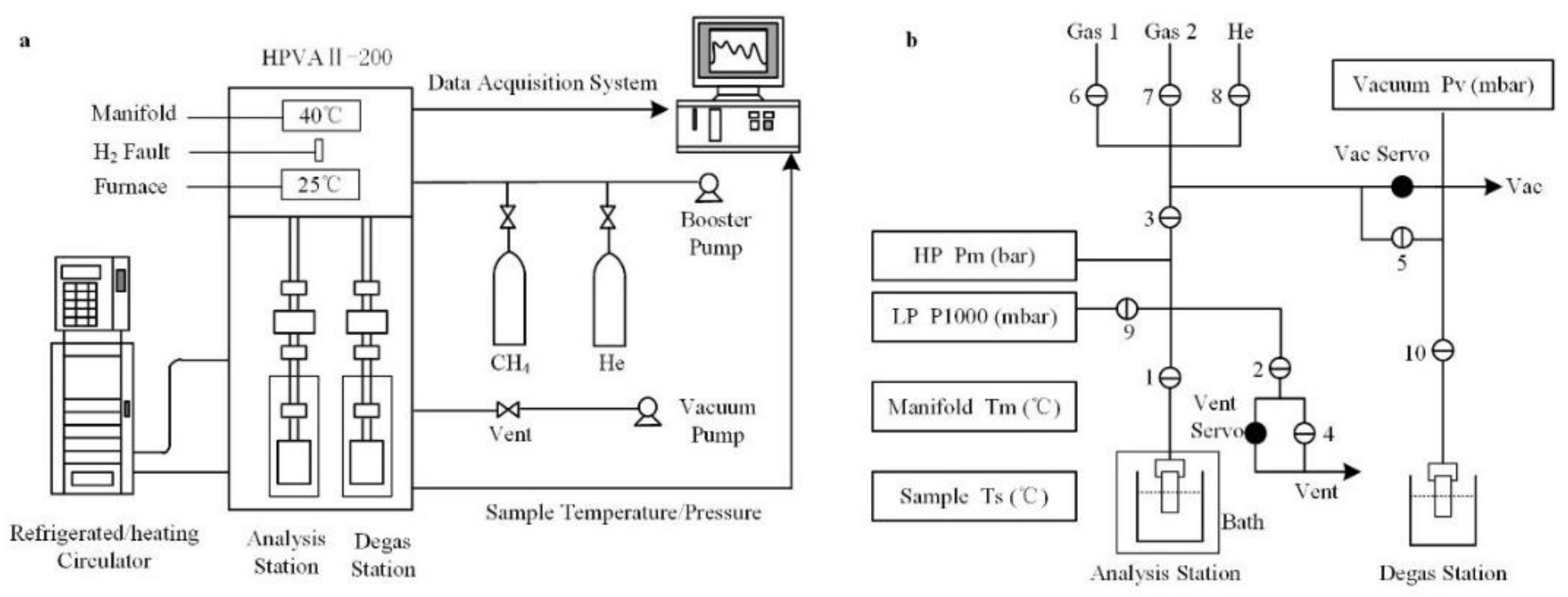
Measurements of adsorption were conducted at temperatures of 20, 40, 60 and 80 °C and pressures of 1–5 MPa for CO2 and 1–15 MPa for CH4, respectively, using a high-pressure volumetric analyzer (HPVAII-200). The HPVAII included a data acquisition system, a degas station, and an analysis station (Figure 2). In addition, an exterior bath was employed to regulate temperature. The accuracy of the temperature transducer was 0.01 °C, and the accuracies of the high-pressure and low-pressure transducers were ±0.04% and ±0.15%, respectively. The accuracy of the measurements was greatly improved because the free spaces at both room temperature and experimental temperature were calculated.
The adsorbed amounts of CO2 and CH4 were calculated through a static volumetric method and the specific experimental procedures were as follows:
(1)
First, the shale was crushed and sieved before use, and a powder of 0.18–0.25 mm in grain size was obtained. This was dried for 8 h at 105 °C to exclude the effect of moisture on the weight measurement.
(2)
Then, the powder was weighed and placed into the sample cylinder, which was subsequently attached to the degas station and evacuated overnight at 105 °C to remove the adsorbed moisture and other gases.
(3)
Next, the cooled cylinder was moved to the analysis station and the manifold was cleaned to avoid contamination by gases in the manifold.
(4)
Finally, the adsorption of gases (CO2 or CH4) experiment was carried out automatically by the HPVA II-200. The experimental data were recorded, and the adsorption isotherms were derived.

2.3. Adsorbed Amount Calculations

The adsorbed amount was determined from the amount of gas dosed into the adsorption cell and the non-adsorbed amount. In order to determine the non-adsorbed amount, we measured the free space, which was the free volume of the adsorption cell excluding shale.

2.3.1. Free Space

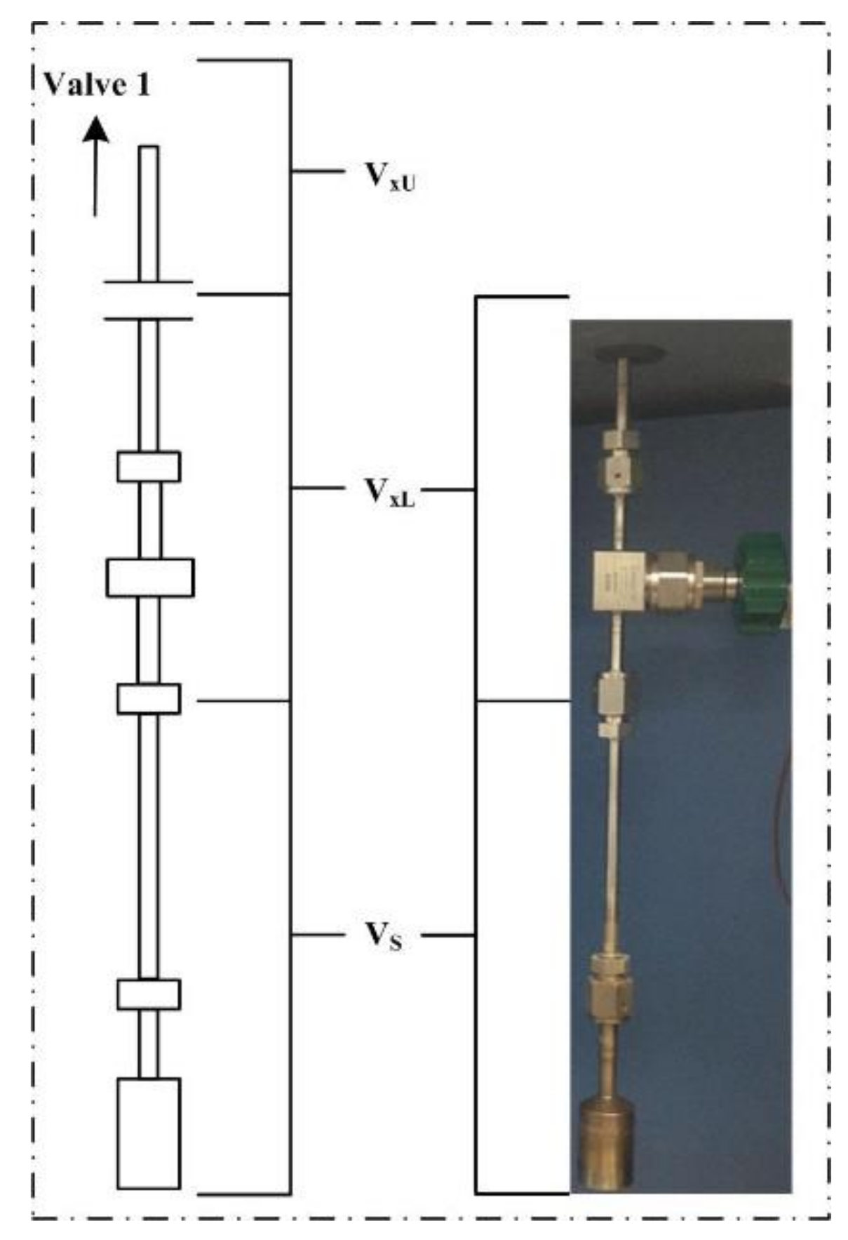
The free space was measured using a helium expansion method. At the experimental temperature, the sample tube, which is shown in Figure 3, contained three temperature zones and the free space (VAFS) was divided into three volumes:
V A F S = V x U + V x L + V S ,
where VxU represents the upper-stem volume, around 3.5 cm3, and VxL and Vs are the lower-stem volume and the adsorption cell volume, respectively.
In order to determine VxL and VS, which were two indispensable values in the following adsorbed amount calculations, two mass balances were established at room temperature (298.15 K) and the experimental temperature, respectively.
At room temperature, the entire system was evacuated to a vacuum. Subsequently, helium was injected into the system (around 0.08 MPa), and when the pressure became stable, Valve 1 between the manifold and the adsorption cell opened. During this process, the pressure and temperature before injection (PA and TA) and after injection (PB and TB) were recorded, and the amount of helium injected into the adsorption cell (nD) was calculated from the following equation:
n D = P A V L P T A z A R P B V L P T B z B R ,
where VLP represents the low pressure manifold volume, 46.7791 cm3.
For the free space analysis at room temperature, because Vs and VxL shared the same temperature and pressure, a new volume VSxL was introduced and expressed as
V S x L = V S + V x L .
Knowing the pressure and temperature of the adsorption cell before (Ps0 = 0 and Ts0) and after injection (Ps1 and Ts1), allowed for the calculation of VSxL and ultimately VAFS from the following expression:
n D + P s 0 V x U T A z x U 0 R + P s 0 V S x L T s 0 z s 0 R = P s 1 V x U T B z x U 1 R + P s 1 V S x L T s 1 z s 1 R .
After analysis of the ambient free space, the adsorption cell was heated to the experimental temperature. Once equilibrium had been reached, the new pressure and temperature of the adsorption cell (Ps2 and Ts2) were measured, and the amount of helium injected into the adsorption cell (nD) at the experimental temperature was calculated in the same way as at room temperature. An extra temperature zone (TAM) was introduced, and a new expression was created to solve Vs and VxL at the experimental temperature, as follows:
n D + P s 0 V x U T A z x U 0 R + P s 0 V x L T A M z x L 0 R + P s 0 V S T s 0 z s 0 R = P s 2 V x U T B z x U 2 R + P s 2 V x L T A M z x L 2 R + P s 2 V S T s 2 z s 2 R .

2.3.2. Adsorbed Amount of Gas

The procedure to determine the adsorption characteristics of the shale was similar to that described for helium expansion. However, instead of using the low-pressure transducer, a high-pressure transducer was used to measure the experimental pressure. The gas (CH4 or CO2) was continuously loaded into the manifold to the preset pressure, automatically and accurately. The pressure and temperature before (P1 and T1) and after injection (P2 and T2) were collected by the data acquisition system, and the amount of gas (CH4 or CO2) injected into the adsorption cell (ndosed) was obtained from the following expression:
n d o s e d = P 1 V H P T 1 z 1 R P 2 V H P T 2 z 2 R ,
where VHP is the high pressure manifold volume, 27.0903 cm3.
The amount of non-adsorbed gas (nNads) was calculated using
n N a d s = P S R ( V S z S T S + V x L z x L T A M + V x U z x U T x U ) ,
where PS is the pressure of the adsorption cell, and TxU and TS were the temperatures of the upper stem and the adsorption cell, respectively.
Knowing ndosed and nNads, the excess adsorbed amount of gas (nex) was calculated using the following equation:
n e x = n d o s e d n N a d s .

2.4. Adsorption Rate Calculations

Mt/M is the ratio between the cumulated excess adsorbed amount at time t and at equilibrium. This is a normalized and widely used parameter that reveals the gas adsorption rate. During the measurements, both the temperature and pressure were recorded and analyzed using a pressure-decay method [22]. Mt/M was obtained from following expression:
y = M t M P 0 P t P 0 P ,
where P0 represents the original pressure after injection, and Pt and P represent the pressures at time t and at equilibrium, respectively. Based on Fick’s II law, the kinetics of CO2/CH4 adsorption on shale were calculated using the simplified diffusion model proposed by Terzyk and Gauden [23,24]. The effective diffusion coefficient (De) was obtained from the following expressions:
M t M = 1 6 π 2 n = 1 1 n 2 exp ( n 2 π 2 D e t ) n = 1 , 2 , 3 .
When 0.0025 ≤ y = Mt/M ≤ 0.8,
f 1 ( y ) = 0.286 × 8.151 y × y 1.453 .
When 0.8 ≤ y = Mt/M ≤ 0.9,
f 2 ( y ) = ( 0.285 0.284 × y ) / ( 1 1.927 × y + 0.927 × y 2 ) .
When f1(y) = f2(y),
π 2 D e t = f 1 ( y ) = f 2 ( y ) .
It should be noted that the effective diffusion coefficient (De) in this work was assumed as a mean value that was not influenced by the time and gas concentration.

3. Modeling

3.1. Langmuir + k Model

The Langmuir model is a common and widely used expression to study adsorption behavior. It was originally proposed assuming there was an equilibrium between the free gas molecules and the adsorbed gas molecules at the adsorption spot, and then modified by Sakurovs et al. [25] using gas density, rather than pressure, as the independent variable. In addition, the ‘Henry’ absorption coefficient k was introduced, and the thermodynamic equilibrium equation of the Langmuir + k model was expressed as:
n e x = n L ( 1 ρ g ρ a ) ρ g ρ g + ρ L + k ρ g ( 1 ρ g ρ a ) ,
where ρg represents the free phase density of the actual gas, which is obtained from PV = zRT. The absorbed phase densities ρa for CO2 and CH4 were 1.027 and 0.421 g/cm3 respectively [25,26,27,28,29]. Furthermore, the adsorption capacity of the surface was expressed by nL, and the gas density (when adsorption was half the maximum) was expressed by ρL. The parameters nL, ρL, and k were obtained from regression fitting.

3.2. Ono–Kondo Lattice Model

The Ono–Kondo lattice model was established using lattice theory, which is more applicable to fitting high-pressure adsorption isotherms. It was improved by Sudibandriyo et al. [30,31] and the equilibrium equation was expressed as
ln [ x t ( 1 x g ) x g ( 1 x t ) ] + z 0 ( x t x g ) ε i i k T + z 2 ( x t + 1 2 x t + x t 1 ) ε i i k T = 0 , t = 2 , 3 , n .
In this equation, k represents the Boltzmann constant and εii/kT represents the fluid–fluid interaction energy. Furthermore, xt and xg are the proportions of the adsorption spots taken up by the adsorbed gas molecules in layer t and by the fluid molecules, respectively. These were expressed as follows:
x t = ρ t ρ a , x g = ρ g ρ a ,
where ρt represents the adsorbed phase density in layer t and ρg represents the bulk phase density.
The absorbed phase densities ρa for CO2 and CH4 were assumed to be 1.027 and 0.421 g/cm3, respectively [25,26,27,28,29]. In this work, only monolayer adsorption was assumed, for the sake of simplification, and the equation was expressed as
ln [ x 1 ( 1 x g ) x g ( 1 x 1 ) ] + ( 7 x 1 8 x g ) ε i i k T + ε i s k T = 0 ,
where εis/kT represents the fluid–solid surface interaction energy. The thermodynamic expression of the Ono–Kondo lattice model was as follows:
n e x = 2 C ( x 1 x g ) = 2 C ( ρ 1 / ρ a ρ g / ρ a ) ,
where C represents a prefactor that correlated with the adsorption capacity and varied with different adsorbents and gases. In this study, the parameters ρ1, C, and εis/k were obtained from the regression fitting while other parameters were obtained from published values [29,31].

4. Results and Discussion

The excess adsorbed amounts and adsorption rates of CO2 and CH4 on shale from China were measured and calculated. Furthermore, the Langmuir + k and Ono–Kondo lattice models were employed to match the adsorption isotherms and the results from fitting the models were compared and discussed.

4.1. Adsorption Capacity

The values of the free space (VAFS) measured in all adsorption experiments were similar (approximately 20 cm3) because VAFS was obtained from the analysis at room temperature. The lower-stem volume (VxL) and adsorption cell volume (VS) were calculated through the analysis at experimental temperature. As we can see in Table 2, the temperature difference between the lower stem and the adsorption cell caused the measured value of Vs to no longer be constant and, instead, it increased with the rising temperature. At this time, it was more like an effective volume, because the actual amount of gas stored in the adsorption cell was influenced by temperature. Furthermore, the Vs values of the CO2 and CH4 adsorption experiments at the same temperature were similar because the free space measurement was completed before the required experimental gas (CO2 or CH4) was loaded into the manifold.
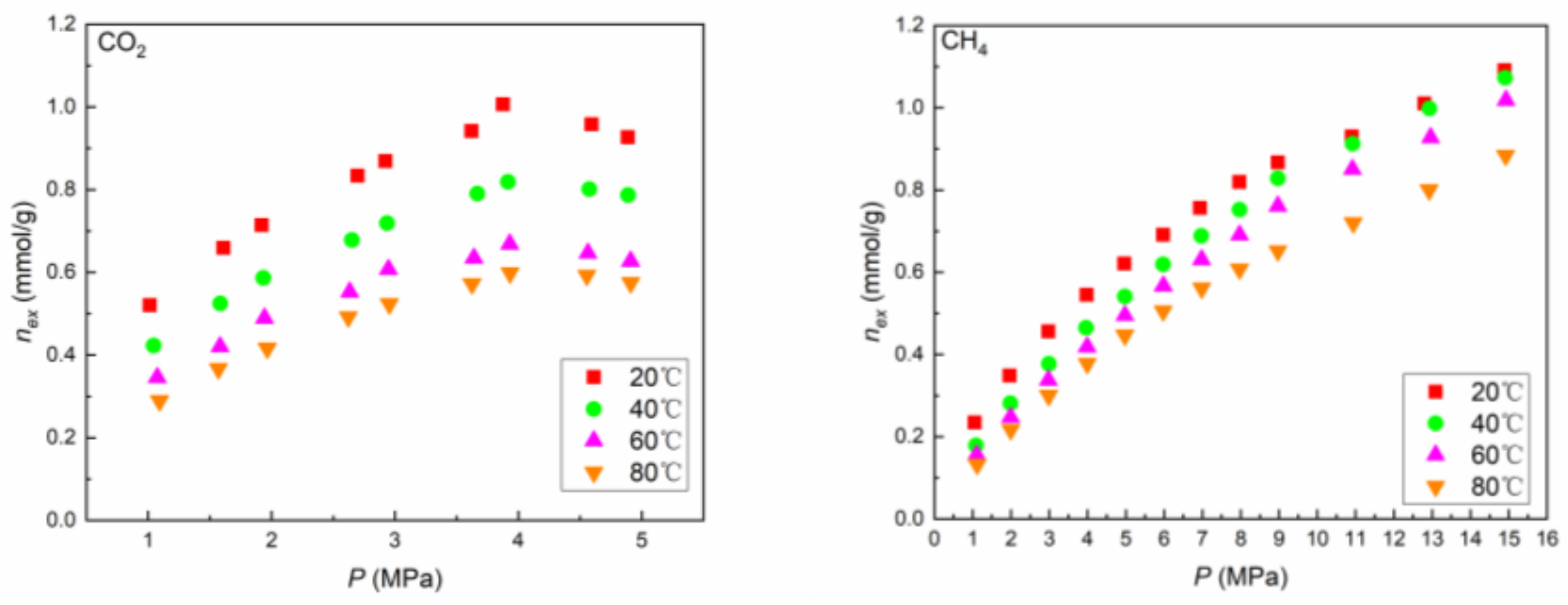
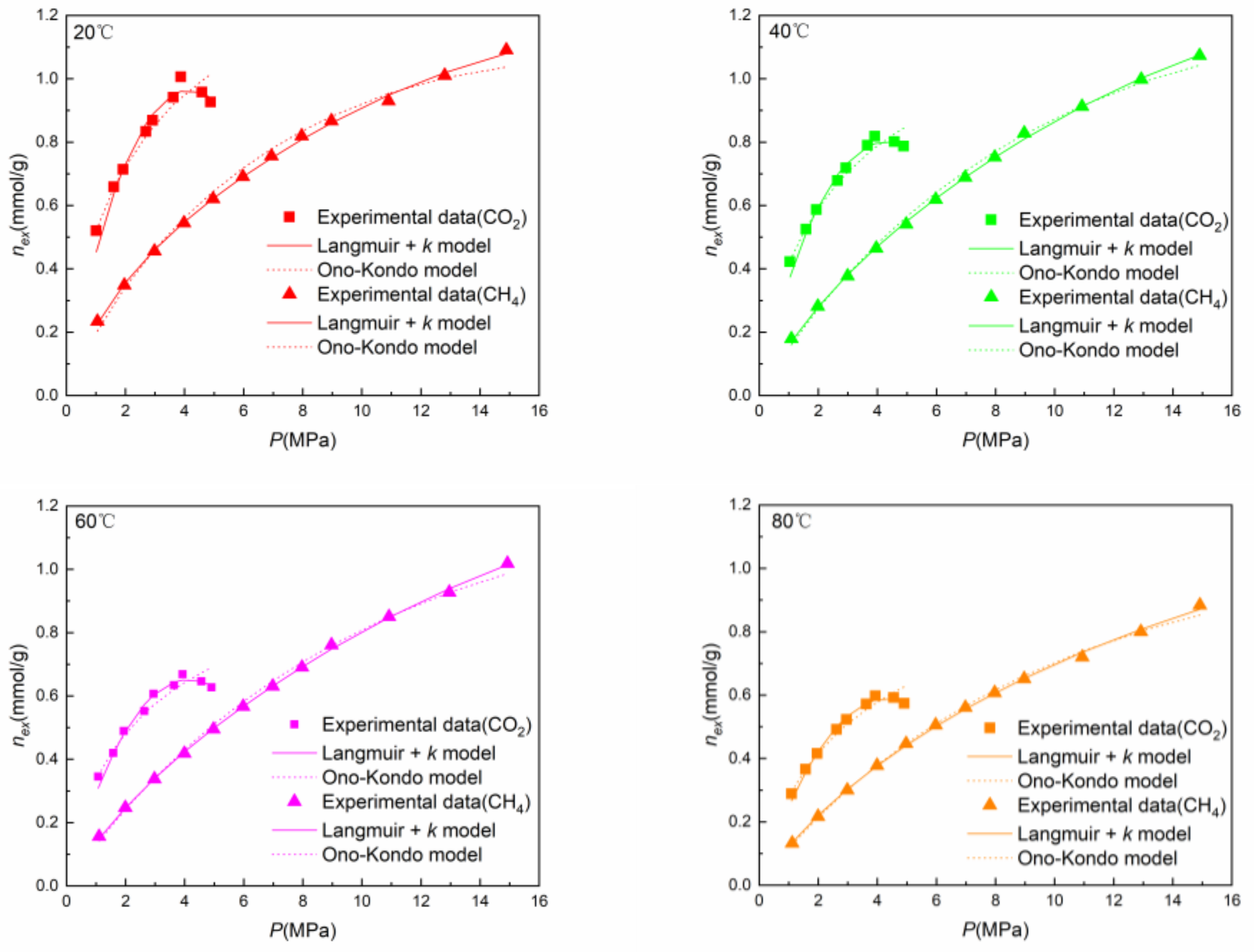
A maximum excess adsorbed amount of CO2 was observed at approximately 4 MPa (Figure 4). A downward trend of excess adsorbed amount of CO2 at relatively high pressures has also been observed in other studies [32,33]. The relationship can be described using the following correlation:
n e x = n a ( 1 ρ g / ρ a ) ,
where nex and na represent the excess and absolute adsorbed amounts, respectively. While ρa represents the adsorbed phase density, the free phase density is expressed as ρg. At the beginning of adsorption, ρg was much smaller than ρa, and nex was close to na. As, ρg increased extremely rapidly with increasing pressure, na increased moderately and eventually remained stable once the majority of adsorptive sites of shale were occupied by CO2 molecules. The rapid and large increase in ρg may be responsible for the downward trend of nex. By contrast, the excess adsorbed amount of CH4 increased with increasing pressure across the entire range of applied pressures. The absence of a maximum in the adsorption isotherm of CH4 may be attributable to the free phase density, ρg, of CH4, which did not change as much as that of CO2 with increasing temperature.

4.2. Adsorption Rates

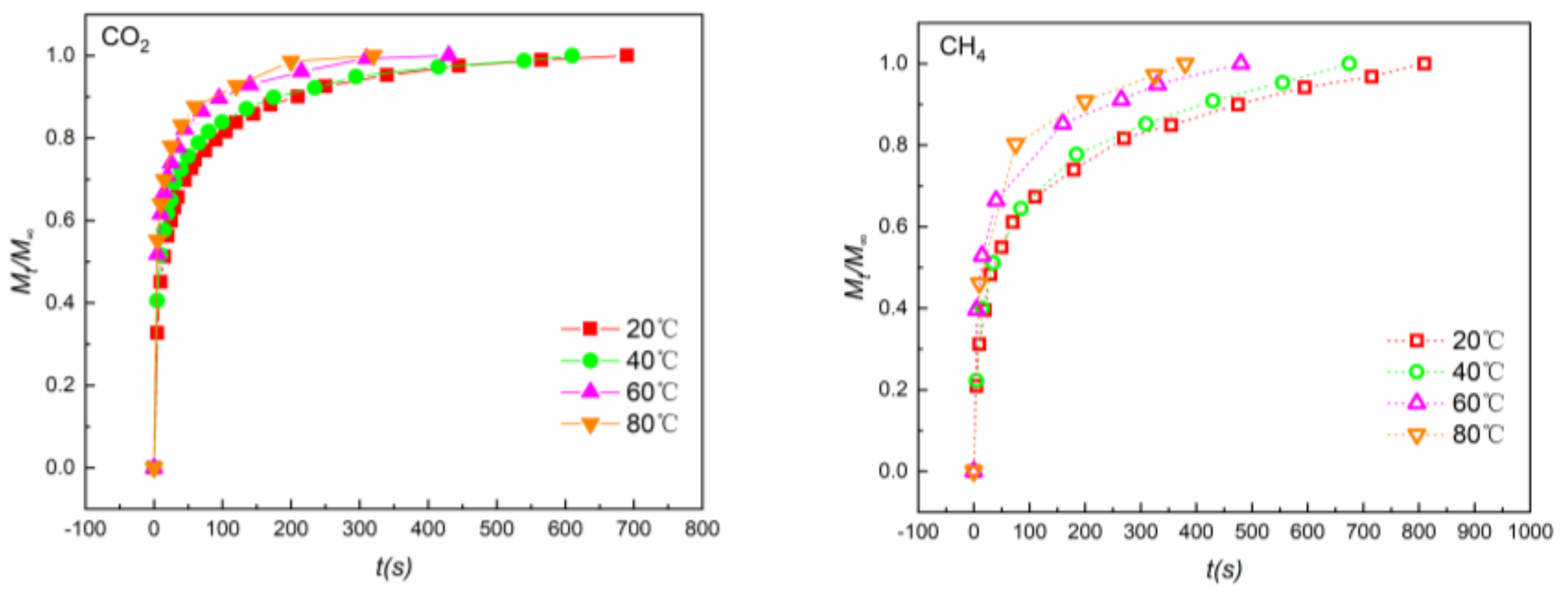
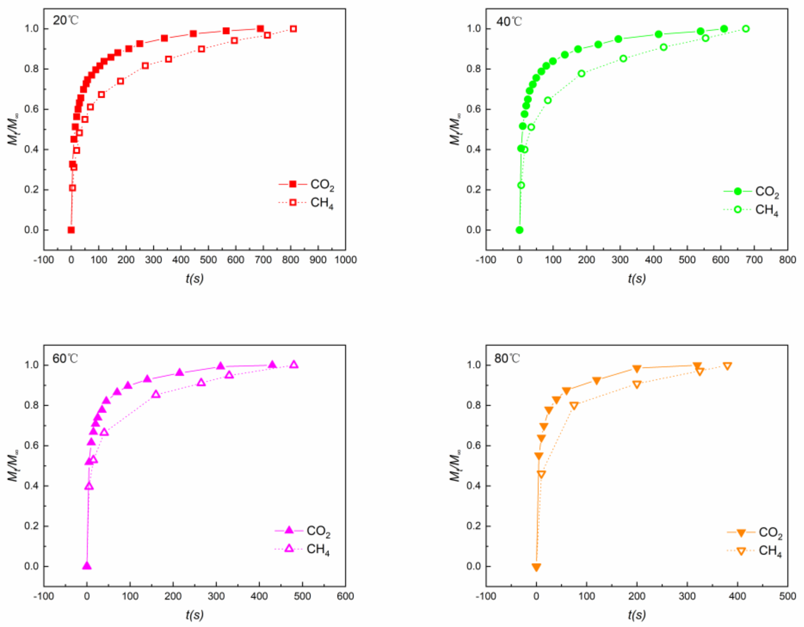
During the experiment, the chamber pressure increased from the lowest to the highest preset values automatically after each measurement was completed. As the presence of adsorbed gas at every pressure step may affect the adsorption rate at each subsequent pressure step, only the adsorption rate at the first preset pressure (1 MPa) was analyzed because the sample cylinder was originally exposed to vacuum prior to the application of the first pressure and before the adsorption started. With increasing temperatures, the time to reach equilibrium of both CO2 and CH4 decreased, which was indicative of increasing rates of adsorption (Figure 5). That was because the increase in temperature resulted in increased Brownian motion.
An equilibrium was reached faster for CO2 than CH4 at all temperatures (Figure 6), and CO2 therefore had a larger adsorption rate than CH4. This may be attributed to the higher affinity between shale and CO2, making it easier for CO2 to diffuse into the micropores on the surface of the shale. CO2 was more active in the competitive adsorption and it was advantageous to the efficiency of CO2-ESGR.
The effective diffusion coefficients (De), which reflect the adsorption rate more directly, are listed in Table 3. In this study, De of CH4 at 40 °C was 0.56 × 10⁻³ s−1, and was smaller than that determined in other studies (0.66 × 10⁻³ s−1 at 2 MPa [34] and 0.82 × 10⁻³ s−1 at 3 MPa [35]). This is because De would increase as the pressure rose. Furthermore, with increasing temperature, the adsorption rates of both CO2 and CH4 increased. While De of CH4 at 80 °C was almost 5 times larger than that at 20 °C, De of CO2 was more than 3 times larger than that at 20 °C. In addition, the adsorption rate of CO2 was much faster than that of CH4 at all temperatures. Taking 40 °C as an example, De of CO2 (1.65 × 10⁻³ s−1) was almost 3 times larger than that of CH4 (0.56 × 10⁻³ s−1).

4.3. Thermodynamic Models

The Langmuir + k and Ono–Kondo lattice models were employed to match the adsorption capacities of shale. The relevant parameters and the tolerance analysis are given in Table 4 and Table 5, respectively. The absolute average deviations (AADs) were calculated using
A A D % = 1 n 1 n | n e x c a l i n e x e x p i n e x e x p i | 100 .
In Equation (19), n is the number of data points, and the subscripts “exp” and “cal” represent experimental and calculated, respectively.
The Langmuir + k model was able to accurately match the adsorption data and the AADs of CO2 and CH4 were 2.12–3.10% and 0.88–1.11%, respectively. For the Ono–Kondo model, the AADs of CO2 and CH4 were 2.70–3.79% and 1.31–3.51%, respectively. Meanwhile, the interaction energy εis/k between CO2 and shale in the Ono–Kondo model was 2–3 times larger than that between CH4 and shale, which revealed that there was a larger affinity between CO2 and shale than between CH4 and shale. This may also account for the relatively larger adsorption rate of CO2. Furthermore, the adsorption behaviors of CO2 and CH4 on shale were accurately described by the Langmuir + k model (Figure 7) and the trend of peaking at approximately 4 MPa for CO2 was replicated by the model. It is notable that a downward trend in the predictive isotherms for CO2 was not apparent in the Ono–Kondo model.
A relatively good adsorptivity for CO2 was exhibited when the applied pressure was less than 5 MPa (Figure 7) and this was beneficial to the implementation of CO2-ESGR. This may be attributable to the linear molecular structure of CO2 and the fact that the molecular dynamics diameter of CO2 is 0.33 nm, which is slightly smaller than that of CH4 (0.38 nm). CH4 cannot diffuse to the ultramicropores on the surface of shale, whereas CO2 can. Although the adsorption experiments for CO2 were only performed at pressures of 1–5 MPa, based on existing experimental data, we deduced that with further increases in pressure, the adsorption capacity of CO2 would be weaker than that of CH4. This was because CO2 would achieve a supercritical state and the density of CO2 would be much larger than that of CH4. Under this circumstance, the injected CO2 would reduce the partial pressure of CH4 for CO2-ESGR and the displacement effect would no longer be significant.

5. Conclusions

This work examined the adsorption behaviors of CO2 and CH4 on shale from China, and two different thermodynamic models were employed to match the adsorption isotherms.
(1)
The excess adsorbed amount of CH4 increased with increasing pressure across the complete range of experimental pressures applied. By contrast, a maximum excess adsorbed amount of CO2 was observed at approximately 4 MPa.
(2)
With increasing temperature, the time to reach equilibrium of both CO2 and CH4 decreased and, therefore, the adsorption rates rose for both gases. CO2 exhibited a larger adsorption rate than CH4. The effective diffusion coefficient De of CO2 (1.65 × 10⁻³ s−1) was almost 3 times larger than that of CH4 (0.56 × 10⁻³ s−1) at 40 °C. This may be attributed to the higher affinity between shale and CO2, making it easier for CO2 to diffuse into the micropores on the surface of the shale.
(3)
The Langmuir + k model predicted the adsorption data well, and the AADs of CO2 and CH4 were 2.12–3.10% and 0.88–1.11%, respectively. The trend of peaking at approximately 4 MPa for CO2 was accurately modeled. From the Ono–Kondo model, the AADs of CO2 and CH4 were 2.70–3.79% and 1.31–3.51%, respectively. The interaction energy εis/k between CO2 and shale in the Ono–Kondo model was 2–3 times larger than that between CH4 and shale, which is indicative of a stronger affinity between CO2 and shale than between CH4 and shale. This also may account for the relatively larger adsorption rate for CO2.
Relatively good adsorptivity for CO2 was exhibited when the pressure was less than 5 MPa and this is beneficial to the implementation of CO2-ESGR. With continuous increases in pressure, the adsorption capacity for CO2 would be smaller than that for CH4. Under this circumstance, the injected CO2 would reduce the partial pressure of CH4 for CO2-ESGR and the displacement effect would no longer be significant. In addition, the adsorption rate of CO2 was much faster than that of CH4 at all temperatures. CO2 was more active in the competitive adsorption and it was advantageous to the efficiency of CO2-ESGR.

Author Contributions

Y.C. conducted the experiments and processed the data. All authors were involved in analyzing the data and writing the paper.

Funding

This research was funded by the National Key Research and Development Program of China (Grant 2016YFB0600804), National Natural Science Foundation of China (Grant 51576031, 51436003, and 51622603) and the Fundamental Research Funds for the Central Universities (Grant DUT18LAB22).

Acknowledgments

The authors appreciate the Qingdao Standard Testing Co., Ltd., which provides the testing report of sample.

Conflicts of Interest

The authors declare no conflict of interest.

References

  1. Song, Y.; Cheng, C.; Zhao, J.; Zhu, Z.; Liu, W.; Yang, M.; Xue, K. Evaluation of gas production from methane hydrates using depressurization, thermal stimulation and combined methods. Appl. Energy 2015, 145, 265–277. [Google Scholar] [CrossRef]
  2. Song, Y.; Wang, X.; Yang, M.; Jiang, L.; Liu, Y.; Dou, B.; Zhao, J.; Wang, S. Study of Selected Factors Affecting Hydrate-Based Carbon Dioxide Separation from Simulated Fuel Gas in Porous Media. Energy Fuels 2013, 27, 3341–3348. [Google Scholar] [CrossRef]
  3. Zhao, J.; Liu, D.; Yang, M.; Song, Y. Analysis of heat transfer effects on gas production from methane hydrate by depressurization. Int. J. Heat Mass Transfer 2014, 77, 529–541. [Google Scholar] [CrossRef]
  4. Zhao, J.; Yu, T.; Song, Y.; Liu, D.; Liu, W.; Liu, Y.; Yang, M.; Ruan, X.; Li, Y. Numerical simulation of gas production from hydrate deposits using a single vertical well by depressurization in the Qilian Mountain permafrost, Qinghai-Tibet Plateau, China. Energy 2013, 52, 308–319. [Google Scholar] [CrossRef]
  5. Zhao, Y.; Song, Y.; Liu, Y.; Liang, H.; Dou, B. Visualization and Measurement of CO2 Flooding in Porous Media Using MRI. Ind. Eng. Chem. Res. 2011, 50, 4707–4715. [Google Scholar] [CrossRef]
  6. Yang, M.; Chong, Z.R.; Zheng, J.; Song, Y.; Linga, P. Advances in nuclear magnetic resonance (NMR) techniques for the investigation of clathrate hydrates. Renew. Sustain. Energy Rev. 2017, 74, 1346–1360. [Google Scholar] [CrossRef]
  7. Yang, M.; Zheng, J.; Liu, W.; Liu, Y.; Song, Y. Effects of C3H8 on hydrate formation and dissociation for integrated CO2 capture and desalination technology. Energy 2015, 93 Pt 2, 1971–1979. [Google Scholar] [CrossRef]
  8. Zheng, J.N.; Yang, M.J.; Liu, Y.; Wang, D.Y.; Song, Y.C. Effects of cyclopentane on CO2 hydrate formation and dissociation as a co-guest molecule for desalination. J. Chem. Thermodyn. 2017, 104, 9–15. [Google Scholar] [CrossRef]
  9. Howarth, R.W.; Santoro, R.; Ingraffea, A. Methane and the greenhouse-gas footprint of natural gas from shale formations. Clim. Chang. 2011, 106, 679–690. [Google Scholar] [CrossRef] [Green Version]
  10. Fathi, E.; Akkutlu, I.Y. Multi-component gas transport and adsorption effects during CO2 injection and enhanced shale gas recovery. Int. J. Coal Geol. 2014, 123, 52–61. [Google Scholar] [CrossRef]
  11. Godec, M.; Koperna, G.; Petrusak, R.; Oudinot, A. Potential for enhanced gas recovery and CO2 storage in the Marcellus Shale in the Eastern United States. Int. J. Coal Geol. 2013, 118, 95–104. [Google Scholar] [CrossRef]
  12. Li, X.; Elsworth, D. Geomechanics of CO2 enhanced shale gas recovery. J. Nat. Gas Sci. Eng. 2015, 26, 1607–1619. [Google Scholar] [CrossRef]
  13. Pei, P.; Ling, K.; He, J.; Liu, Z. Shale gas reservoir treatment by a CO2 -based technology. J. Nat. Gas Sci. Eng. 2015, 26, 1595–1606. [Google Scholar] [CrossRef]
  14. Gasparik, M.; Bertier, P.; Gensterblum, Y.; Ghanizadeh, A.; Krooss, B.M.; Littke, R. Geological controls on the methane storage capacity in organic-rich shales. Int. J. Coal Geol. 2014, 123, 34–51. [Google Scholar] [CrossRef]
  15. Liu, F.; Ellett, K.; Xiao, Y.; Rupp, J.A. Assessing the feasibility of CO2 storage in the New Albany Shale (Devonian–Mississippian) with potential enhanced gas recovery using reservoir simulation. Int. J. Greenhouse Gas Control 2013, 17, 111–126. [Google Scholar] [CrossRef]
  16. Sun, H.; Yao, J.; Gao, S.-H.; Fan, D.-Y.; Wang, C.-C.; Sun, Z.-X. Numerical study of CO2 enhanced natural gas recovery and sequestration in shale gas reservoirs. Int. J. Greenhouse Gas Control 2013, 19, 406–419. [Google Scholar] [CrossRef]
  17. Yuan, W.; Pan, Z.; Li, X.; Yang, Y.; Zhao, C.; Connell, L.D.; Li, S.; He, J. Experimental study and modelling of methane adsorption and diffusion in shale. Fuel 2014, 117, 509–519. [Google Scholar] [CrossRef]
  18. Gu, M.; Xian, X.; Duan, S.; Du, X. Influences of the composition and pore structure of a shale on its selective adsorption of CO2 over CH4. J. Nat. Gas Sci. Eng. 2017, 46, 296–306. [Google Scholar] [CrossRef]
  19. Weniger, P.; Kalkreuth, W.; Busch, A.; Krooss, B.M. High-pressure methane and carbon dioxide sorption on coal and shale samples from the Paraná Basin, Brazil. Int. J. Coal Geol. 2010, 84, 190–205. [Google Scholar] [CrossRef]
  20. Chareonsuppanimit, P.; Mohammad, S.A.; Robinson, R.L.; Gasem, K.A.M. High-pressure adsorption of gases on shales: Measurements and modeling. Int. J. Coal Geol. 2012, 95, 34–46. [Google Scholar] [CrossRef]
  21. Du, X.-D.; Gu, M.; Duan, S.; Xian, X.-F. Investigation of CO2–CH4 Displacement and Transport in Shale for Enhanced Shale Gas Recovery and CO2 Sequestration. J. Energy Resour. Technol. 2016, 139, 012909. [Google Scholar] [CrossRef]
  22. Busch, A.; Gensterblum, Y.; Krooss, B.M.; Littke, R. Methane and carbon dioxide adsorption–diffusion experiments on coal: Upscaling and modeling. Int. J. Coal Geol. 2004, 60, 151–168. [Google Scholar] [CrossRef]
  23. Terzyk, A.P.; Gauden, P.A. The simple procedure of the calculation of diffusion coefficient for adsorption on spherical and cylindrical adsorbent particles--experimental verification. J. Colloid Interface Sci. 2002, 249, 256–261. [Google Scholar] [CrossRef]
  24. Terzyk, A.P.; Gauden, P.A. The Simple Procedure of the Calculation of Diffusion Coefficient for Adsorption on Spherical and Cylindrical Adsorbent Particles. Sep. Sci. Technol. 2007, 36, 513–525. [Google Scholar] [CrossRef]
  25. Sakurovs, R.; Day, S.; Weir, S.; Duffy, G. Application of a Modified Dubinin-Radushkevich Equation to Adsorption of Gases by Coals under Supercritical Conditions. Energy Fuels 2007, 21, 992–997. [Google Scholar] [CrossRef]
  26. Day, S.; Duffy, G.; Sakurovs, R.; Weir, S. Effect of coal properties on CO2 sorption capacity under supercritical conditions. Int. J. Greenhouse Gas Control 2008, 2, 342–352. [Google Scholar] [CrossRef]
  27. Gensterblum, Y.; van Hemert, P.; Billemont, P.; Battistutta, E.; Busch, A.; Krooss, B.M.; De Weireld, G.; Wolf, K.H.A.A. European inter-laboratory comparison of high pressure CO2 sorption isotherms II: Natural coals. Int. J. Coal Geol. 2010, 84, 115–124. [Google Scholar] [CrossRef]
  28. Sakurovs, R.; Day, S.; Weir, S. Relationships between the Critical Properties of Gases and Their High Pressure Sorption Behavior on Coals. Energy Fuels 2010, 24, 1781–1787. [Google Scholar] [CrossRef]
  29. Zhang, Y.; Xing, W.; Liu, S.; Liu, Y.; Yang, M.; Zhao, J.; Song, Y. Pure methane, carbon dioxide, and nitrogen adsorption on anthracite from China over a wide range of pressures and temperatures: Experiments and modeling. RSC Adv. 2015, 5, 52612–52623. [Google Scholar] [CrossRef]
  30. Sudibandriyo, M.; Mohammad, S.A.; Robinson, R.L.; Gasem, K.A.M. Ono–Kondo Model for High-Pressure Mixed-Gas Adsorption on Activated Carbons and Coals. Energy Fuels 2011, 25, 3355–3367. [Google Scholar] [CrossRef]
  31. Sudibandriyo, M.; Mohammad, S.A.; Robinson, R.L., Jr.; Gasem, K.A.M. Ono–Kondo lattice model for high-pressure adsorption: Pure gases. Fluid Phase Equilib. 2010, 299, 238–251. [Google Scholar] [CrossRef]
  32. Bakhshian, S.; Hosseini, S.A. Prediction of CO2 adsorption-induced deformation in shale nanopores. Fuel 2019, 241, 767–776. [Google Scholar] [CrossRef]
  33. Gasparik, M.; Rexer, T.F.T.; Aplin, A.C.; Billemont, P.; De Weireld, G.; Gensterblum, Y.; Henry, M.; Krooss, B.M.; Liu, S.; Ma, X.; et al. First international inter-laboratory comparison of high-pressure CH4, CO2 and C2H6 sorption isotherms on carbonaceous shales. Int. J. Coal Geol. 2014, 132, 131–146. [Google Scholar] [CrossRef]
  34. Wang, J.; Yang, Z.; Dong, M.; Gong, H.; Sang, Q.; Li, Y. Experimental and Numerical Investigation of Dynamic Gas Adsorption/Desorption–Diffusion Process in Shale. Energy Fuels 2016, 30, 10080–10091. [Google Scholar] [CrossRef]
  35. Wang, J.; Wang, B.E.; Li, Y.; Yang, Z.; Gong, H.; Dong, M. Measurement of dynamic adsorption–diffusion process of methane in shale. Fuel 2016, 172, 37–48. [Google Scholar] [CrossRef]
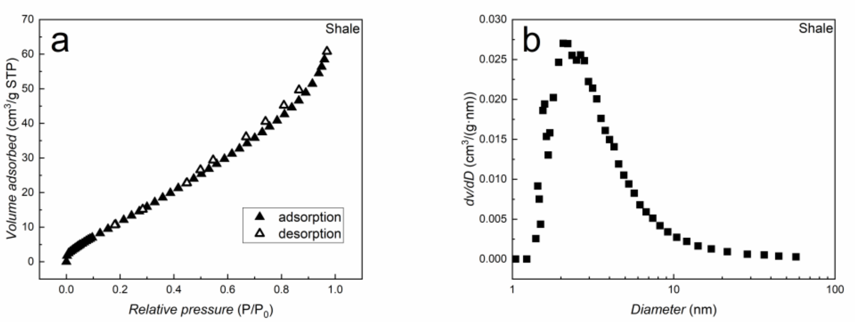
Figure 1. (a) N2 adsorption (solid) and desorption (hollow) isotherms and (b) pore size distribution of crushed shale.
Energies 12 00978 g001
Figure 2. Schematic diagrams of (a) experimental system and (b) HPVA II-200.
Energies 12 00978 g002
Figure 3. Three sections of the sample tube.
Energies 12 00978 g003
Figure 4. The excess adsorbed amounts of CO2 and CH4 on the shale sample.
Energies 12 00978 g004
Figure 5. Adsorption rates of CO2 and CH4 at 1 MPa.
Energies 12 00978 g005
Figure 6. Comparison of adsorption rates between CO2 and CH4 at different temperatures.
Energies 12 00978 g006
Figure 7. Comparison of adsorption isotherms between CO2 and CH4 at different temperatures.
Energies 12 00978 g007
Table 1. Compositional analysis of the shale sample.
Ultimate Analysis (Dry wt % Basis)Proximate Analysis (wt %)
NCSHMoistureAshTOC
0.73224.663.0012.1614.0457.884.91
Table 2. The adsorption cell volume at experimental temperatures.
T (K)293313333353
Vs (cm3)CO27.298.168.979.78
CH47.318.178.919.72
Table 3. The effective diffusion coefficients of CO2 and CH4 at 1 MPa.
De (× 10−3 s−1)20 °C40 °C60 °C80 °C
CO21.231.652.944.16
CH40.490.561.612.48
Table 4. Parameters and tolerance analysis of the Langmuir + k model a.
T (K)nnL (mmol·g−1)ρL (g·cm−3)k (cm3·g−1)AAD
CO2293.2093.04300.0824−5.99533.10%
312.7993.22520.0959−7.57702.54%
333.1195.66480.1526−15.52112.47%
353.3598.93700.2184−21.97972.12%
CH4293.13120.52440.01498.63471.11%
313.14120.44710.02229.99301.03%
333.32120.39600.023610.32260.88%
353.33120.44600.02668.59701.06%
an: Number of data points estimated. AAD, absolute average deviation.
Table 5. Parameters and tolerance analysis of the Ono–Kondo lattice model.
T (K)nρ1 (g·cm−3)C (mmol·g−1) εis/k (K)AAD
CO2293.2090.68670.9435−1066.23.11%
312.7990.62490.8418−1088.72.70%
333.1090.60040.7022−1152.13.79%
353.3590.53300.7196−1121.13.08%
CH4293.13120.24761.7363−483.33.51%
313.14120.19442.5245−363.72.91%
333.32120.17342.7091−351.42.40%
353.31120.17352.1090−420.51.31%