Review

Review of Core/Shell Quantum Dots Technology Integrated into Building’s Glazing

by
Amira R. AbouElhamd
1,
Khaled A. Al-Sallal
2,* and
Ahmed Hassan
2
1
Emirates Centre for Energy and Environment Research (ECEER), UAE University, Al Ain 15551, UAE
2
Department of Architectural Engineering, UAE University, Al Ain 15551, UAE
*
Author to whom correspondence should be addressed.
Energies 2019, 12(6), 1058; https://doi.org/10.3390/en12061058
Submission received: 12 November 2018 / Revised: 15 February 2019 / Accepted: 18 February 2019 / Published: 19 March 2019
(This article belongs to the Section A: Sustainable Energy)

Abstract

:
Skylights and windows are building openings that enhance human comfort and well-being in various ways. Recently, a massive drive is witnessed to replace traditional openings with building integrated photovoltaic (BIPV) systems to generate power in a bid to reduce buildings’ energy. The problem with most of the BIPV glazing lies in the obstruction of occupants’ vision of the outdoor view. In order to resolve this problem, new technology has emerged that utilizes quantum dots semiconductors (QDs) in glazing systems. QDs can absorb and re-emit the incoming radiation in the desired direction with the tunable spectrum, which renders them favorable for building integration. By redirecting the radiation towards edges of the glazing, they can be categorized as luminescent solar concentrators (QD-LSCs) that can help to generate electricity while maintaining transparency in the glazing. The aim of this paper is to review the different properties of core/shell quantum dots and their potential applications in buildings. Literature from various disciplines was reviewed to establish correlations between the optical and electrical properties of different types, sizes, thicknesses, and concentration ratios of QDs when used in transparent glazing. The current article will help building designers and system integrators assess the merits of integrating QDs on windows/skylights with regards to energy production and potential impact on admitted daylighting and visual comfort.

1. Introduction

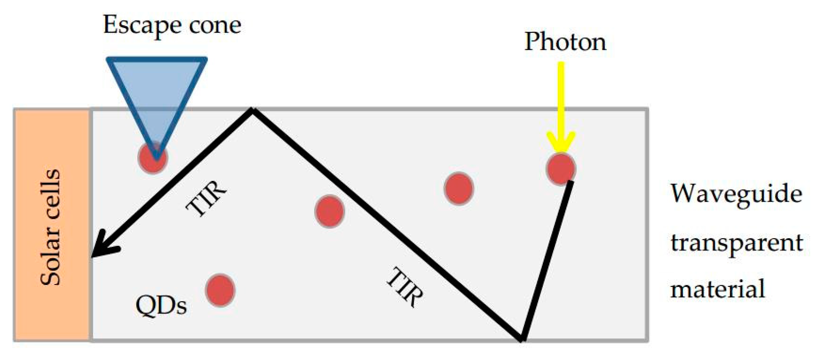
Buildings’ openings are considered a crucial element to visually connect to the outside and admit daylighting to the indoor spaces. In recent years, the building industry has been increasingly shifting from typical glazing systems to building integrated photovoltaics (BIPV) in a bid to reduce building reliance on supply from the electrical grid. The BIPV adaptation to buildings is affecting daylight admission and the view factor in buildings; which can lead to health and psychological issues according to previous studies. Recent studies introduced a number of approaches to develop transparent BIPV to overcome the daylight and view related issues [1,2]. The most promising technique is to use QDs that help to improve energy production by involving better sunlight absorption and re-emission in the desired direction [3,4]. The tunable absorption and emission feature of the QDs render them attractive for use on glazing systems to control the intensity and wavelength of the produced light. The general principle when QDs are applied on glazing systems involves the absorption of refracted incident light that reaches the surface, and re-emission at tuned frequencies in the desired direction. This causes a release of photons that can travel to the edge of the glazing material with a total internal reflection (TIR) to be collected for energy production or could reflect internally within the device surface. A portion of the emitted photons can exit through the top surface of LSCs and may be lost into the ambience through the optical escape cone thereby not taking part in the electrical conversion process that limits the efficiency of the LSCs. Generally, spectral overlap occurs between the absorption and emission spectra of QDs, which forecasts the re-absorption of the released photons and hence facilitates their degradations that eventually reduces the optical efficiency of the QDs. QDs emit light with various wavelengths in different ranges of the solar spectrum that determines their classifications and potential applications.
QDs are semiconductor nanocrystals with diameters that typically vary from 10′s to 100′s nanometers providing distinct electronic and optical properties. Structurally, the plain QDs consist of a metalloid crystalline core covered with an organic outside layer [5,6]. An additional layer called the ‘shell’ could be added to form many types of core/shell QDs, as shown in Figure 1. This layer improves the light harvesting properties for high energy level photons. Another way to improve the properties of QDs is by doping some ions, such as Mn2+ and Cu2+, in the core/shell QDs configurations. The doped ions are proven to further improve the optical and electrical properties of the core/shell QDs; which render them useful for various applications [7,8,9]. Tuning the size of the QDs can help control the absorption and emission spectrum in the desired direction [3,10,11,12,13,14,15,16,17]. The extent of absorption and re-emission of these photons determines the effectiveness of QDs.
This article discusses different types of core/shell QDs based on their band gap alignment, and the associated properties for each type. The aim is to review the properties, characteristics, and behavior of different types of QDs. The scope of the review is to evaluate QDs as the Luminescent Solar Concentrators (QDs-LSC), and highlight their potential benefits in generating electricity while creating a pleasant daylit indoor environment. The optical and electrical properties of different types of core/shell QDs in the QDs-LSC technology are reviewed based on their materials, sizes, and concentrations. The review will be useful to support ongoing related research with regards to engineering the absorption and emission phenomenon for a transparent power-generating glass.

2. Characteristics of Core/Shell QDs

2.1. Types of Core/Shell QDs Based on Band Gap

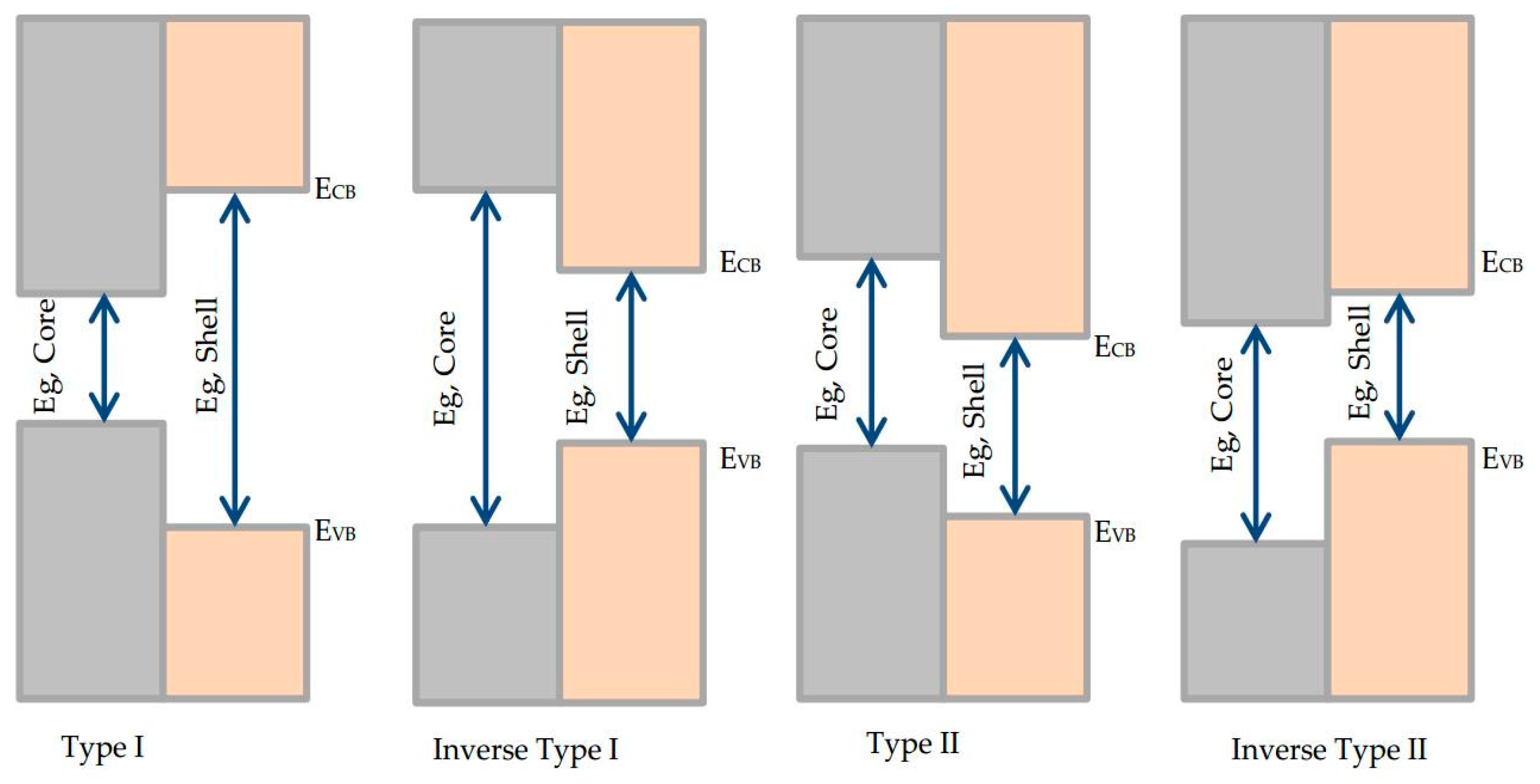
According to the edge alignment of the conduction and valence bands of the core and shell structures in the core/shell QDs, they are classified into four main types as follows: Type I, Inverse Type I, Type II, and Inverse Type II. Figure 2 shows the band gap alignments for each of the four types [18,19,20,21,22,23,24]. Table 1 compares QDs classification based on their band alignment, the location of carriers, quantum yields, stokes shift, and the average absorption and emission ranges. It also provides examples of core/shell QDs and lists some of their limitations.
It can be observed from the Table 1 that moving from Type 1 to Type 2, the bandgap difference between core and shell reduces and the exited electrons are spatially departed from each other. The stokes shift increased while the quantum yield and stability decreased with increasing absorption wavelength. In renders the type 1 more favorable as concentrators compared to type 2 as they show no leakage of excited electrons, show better stability and also offer higher QY. In addition to these types, type I-III-VI2 core/shell QDs exhibit NIR emission characteristics, which are favorable to have a full control over the lighting spectrum. They have narrow band-gap (1.02 eV), strong absorbance across the solar spectrum that could reach up to 30%, and high photoluminescence quantum yield (QY) of 65–75%. They also have a large Stokes shift (Δs) between the photoluminescence (PL) band, which indicates that the QDs have unusual emission mechanism. The PL emission occurs due to transition between the conduction-band excited electron and the localized hole residing in an intra-gap state [35,36,37,38]. A potential advantage of such QDs lies in higher photoluminescence quantum yield (>60%) even for high wavelengths (NIR at 800 nm), where other types become poor emitters (<10%). This type includes CuInS2/ZnS, CuInSexS2–x, and CuInS2Se1-x/ZnS.

2.2. Stocks Shift and Absorption and Emission Properties of Core/Shell QDs

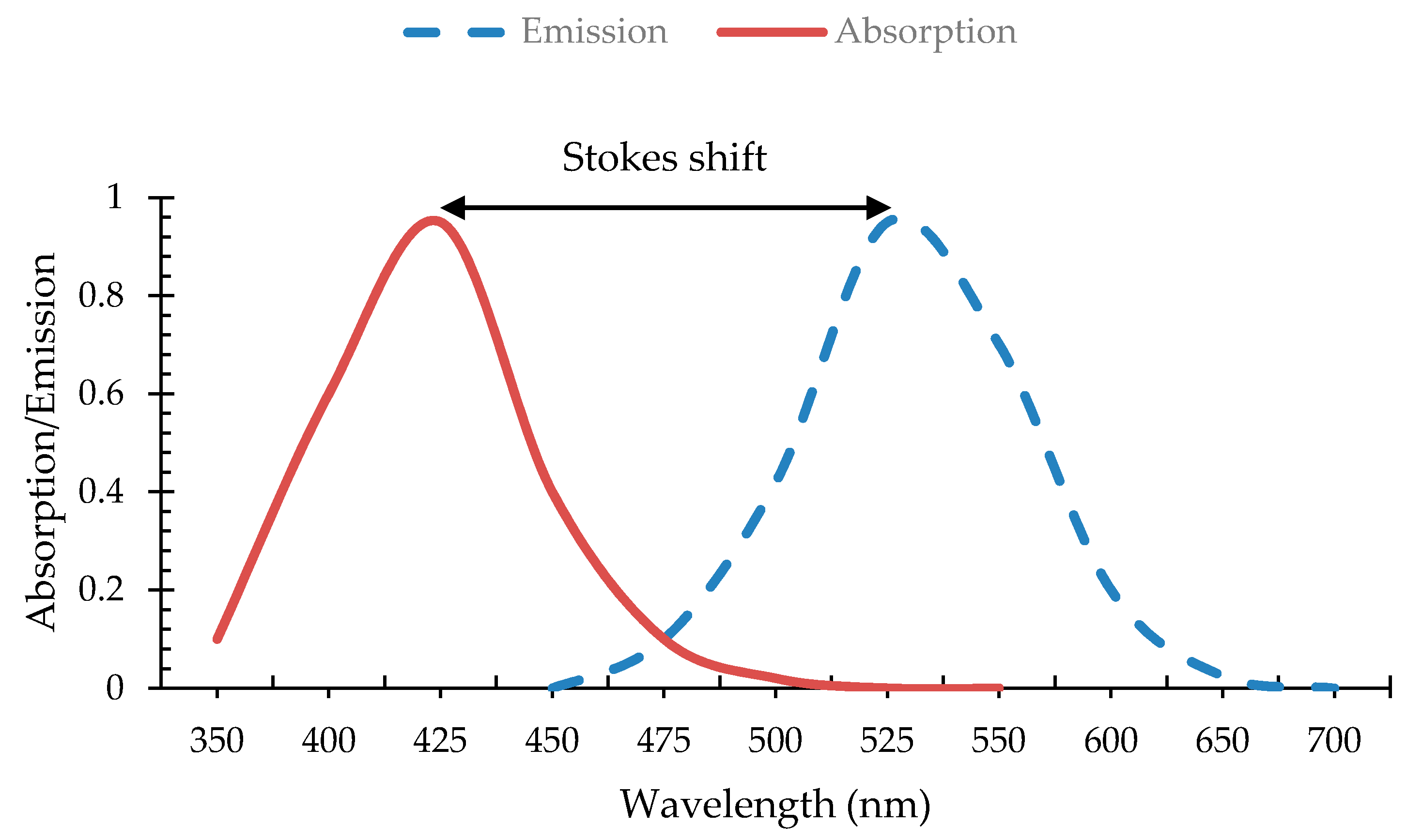
The stokes shift is the difference between the peak of the absorption and the peak of the emission wavelengths, as shown in Figure 3 [39]. From an optical point of view, it leads to less possibility of reabsorption and thus reduction of potential energy losses. While the re-emission spectra shifts to a higher wavelength, this paradoxically leads to an energy reduction in the re-emitted photon; because the difference in energy is dissipated as thermal losses in the QDs. Hence, the effect of the stokes shift needs to be investigated carefully to avoid any unexpected results.
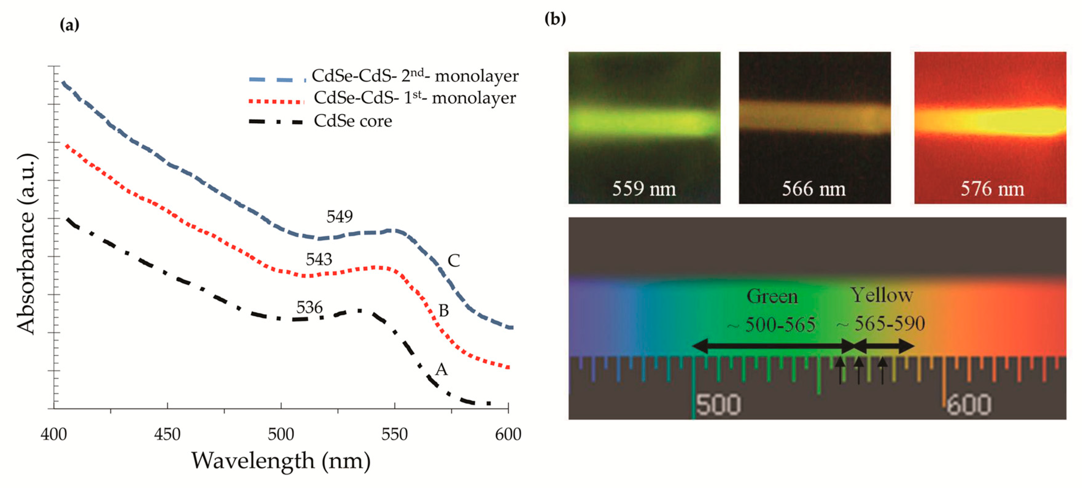
The absorption and emission spectrum of the QDs should match that of the solar spectrum in order to absorb photons with the same wavelengths [3]. Controlling the absorption and emission phenomenon in the core/shell QDs structure is achieved by tuning the size of the core and the thickness of the shell [40]. Ramanery et al. [29] investigated the optical properties of different shell thicknesses for the CdSe/CdS type I core/shell QDs (absorption range is 400–600 nm). Figure 4a illustrates the UV-Vis absorption spectra for: (A) The CdSe core only; (B) the CdSe with the 1st monolayer of CdS; and (C) the CdSe with the 2nd monolayer of CdS. Increasing the shell thickness was found to shift the overall absorption spectra to a higher wavelength (lower energy, or a redshift), leading to a total absorption shift of around 13 nm for two layers of coverage. The CdS shell attracts excited electrons in the CdSe core, leaving the holes inside the core. This separation lowers the energy of exciton causing the redshift for the CdSe/CdS core/shell QDs. Figure 4b shows the images of Fluorescence spectra of the CdSe/CdS QDs with different shell thicknesses. This figure shows the color of the emitted light shifting from green to yellow (low wavelength to high wavelength). This means that the emission spectrum was shifted to higher wavelengths for thicker shells. Therefore, one can conclude that controlling the thicknesses of the shells not only controls the absorption and emission spectrum, but also enables for the control of the coloring of the emitted light.
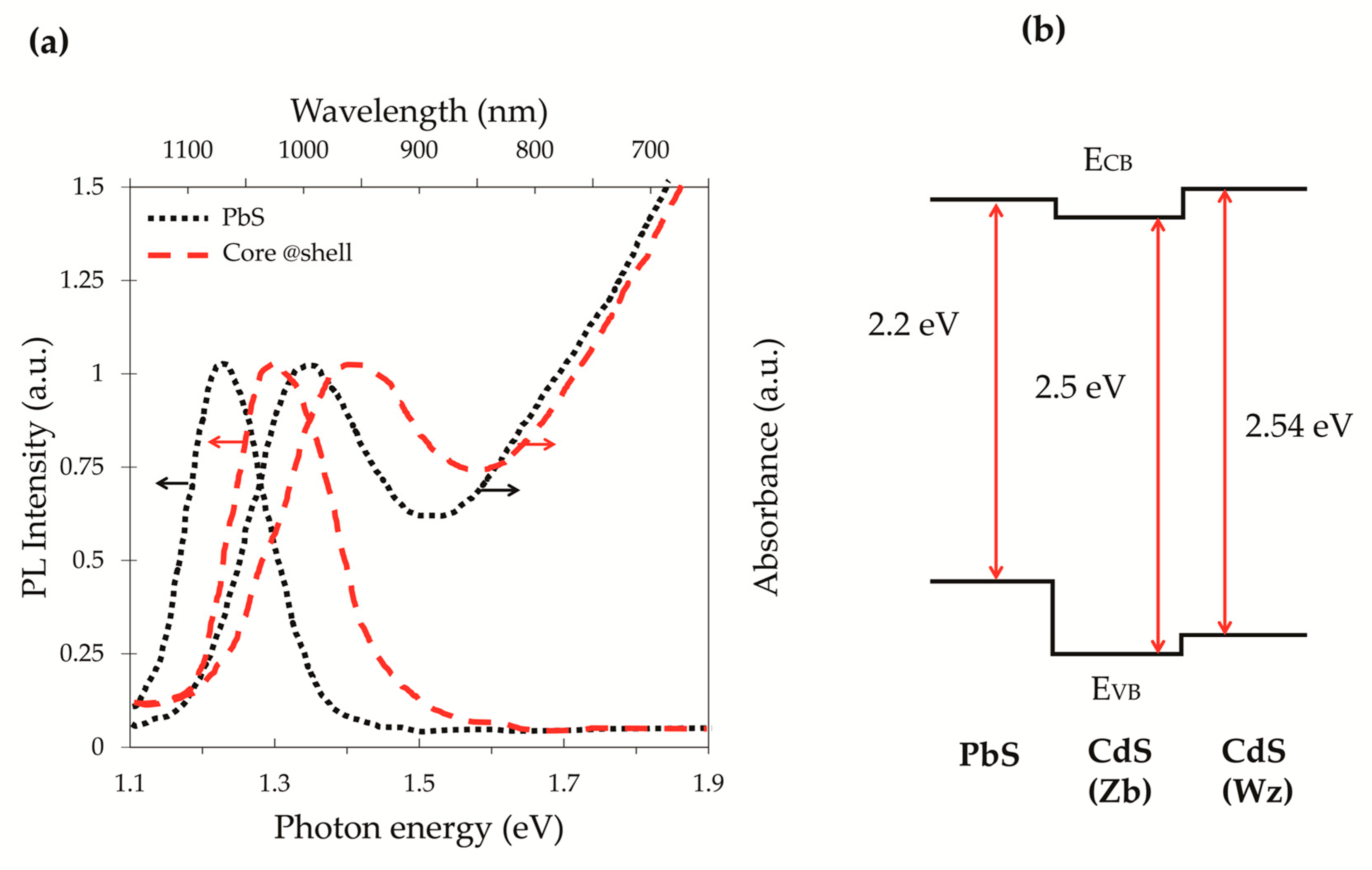
Additional ranges of the solar spectrum could be absorbed by using pure QDs like PbS or core/shell QDs like PbS/CdS to reach up to NIR spectrum. This type of QDs emits light in wavelengths ranges from 700 nm to 2500 nm, falling within near infrared (NIR) thus they being termed as NIR QDs. Figure 5a reports the optical absorption spectra and the PL spectra for the pure PbS and the PbS/CdS core/shell QDs [41]. QDs of the inverse type II core/shell QDs are very efficient in capturing a wide range of solar radiations, since their absorption spectrum typically covers a huge range of UV-Vis-NIR (600–1600 nm), as shown in Table 1. For the PbS/CdS core/shell QDs, the optical properties are adjusted by tuning the size of the starting core PbS, and thickness of the CdS shell through controlling the reaction parameters during their synthesis [18]. The shrinkage of the PbS core size that occurs during the synthesis process of the QDs fabricated from PbS/CdS shifts the PL emission peak to lower wavelengths. Nonetheless, the absorption properties of the PbS core still exist in the ranges of 550–600 nm, where the PbS core is still active [42]. Tuning the shell thickness of the PbS/CdS QDs causes absorption peak varying from 700 nm to 1600, and emission peak varying from 850 to 1000 nm [34]. The QY of the PbS/CdS QDs also increases for thicker shells and the typical range for the QY varies from 30% to 90% [18,43,44,45]. To further enhance the optical properties, an additional CdS shell could be added to form PbS/CdS/CdS core/shell/shell QDs [42]. This structure produced double color emission with two emission peaks at 480 nm and 650 nm. The PbS/CdS/CdS QDs system have an inverse type II structure, where the excited electrons are delocalized into the structure and the holes relaxed in the core, as shown in Figure 5b. It has a thin layer of zinc blende (Zb) phase CdS sandwiched between the core and the thick wurtzite (Wz) CdS shell. The double shell structure helped control the electronic band structure which in turns regulated the color of the emission. It was found that both the absorption and emission spectral ranges increased for thicker shells of the PbS/CdS/CdS QDs. Commonly, using CdS as an external shell hugely improves the stability of the QDs and enriches their overall QY [45].

3. QDs as Concentrators

There is a strong desire to benefit from the unique tunable absorption and emission properties of QDs. A recent technology that incorporates QDs in transparent materials is the Luminescent Solar Concentrators (QDs-LSC). In this technology, QDs are used as fluorescent dyes to harvest solar radiations and convert them into electricity. The following sections introduce the merits of the QDs-LSC technology via discussions of the electrical and optical characteristics of the system and its performance output utilizing different types, sizes, and concentrations of QDs.

3.1. Luminescent Solar Concentrators Based on Quantum Dots (QD-LSC)

The luminescent solar concentrators (LSC) technology was introduced to replace the large area solar cells with inexpensive collectors and hence reduce the cost of a module [3,46]. It consists of a waveguide transparent material, such as polymer or glass, doped with luminescent species, such as an organic dye or quantum dots while Si PV cells are attached to the edges of the transparent material. The general principle in the QDs-LSC involves a photon absorbed by the QDs on the faces exposed to incoming radiation within the LSC system, re-emitted with larger wavelength, and wave-guided with TIR to the edge of the waveguide transparent material where they can be converted to electricity, as shown in Figure 6.
The LSC technology has several advantages over other concentrating systems in that it concentrates both direct and diffused solar radiations, it is not limited by a concentration ratio, and fewer losses are associated with the solar cells in the LSC technology, due to wavelength tuning of the re-emitted radiation within the desired spectral response of the solar cells [47,48]. There are various applications of the LSC technology, such as using them as collectors in semitransparent windows, electronic devices, and fiber optics [3,49] and as photon transport for passive daylighting [50,51]. Nevertheless, since this system relies mainly on photon transport over a macroscopic distance, it suffers from several loss mechanisms. For a waveguide made of glass or plastic (Figure 6), around 75% of the emitted photons are successfully trapped in the waveguide, while the remaining are lost in the ‘escape cone’ as defined by Snell’s law [46]. The trapped photons can still be lost either by scattering within the waveguide surface, or by the internal reflection, or via the self-absorption. Self-absorption is a crucial loss factor that causes irradiative decay in the escape cone [46]. It happens when the photons that were emitted from one QD were absorbed by another QD instead of reaching the edge of the waveguide. The reabsorption has historically limited the implementation of the large-scale LSC [52]. Other loss mechanisms include unabsorbed light, reflected light from the top surface, and photon losses, due to the non-unity of the QD quantum yield.
The performance of the QD-LSC is affected by the optical properties of the QDs and the waveguide matrix. The optical properties of the QDs are influenced by their absorption coefficient and its overlap with the solar spectrum, their QY, stokes shift, stability, and solubility in the transparent waveguide material. The following sections discuss the optical and electrical characteristics of the LSC based on different types of core/shell QDs.

3.1.1. LSC with Type I core/shell QDs

In type I core/shell QDs, wide band gap shells, such as ZnS and CdS, are applied to core semiconductors like CdSe and CdS. These wide band gap shells improve the light harvesting properties of visible light when used as Quantum Dots Solar Concentrators (QDSC) [53,54,55]. As mentioned in the previous sections, while type I core/shell QDs have high QY and enhanced stability, they suffer from small stokes shift, due to the overlap between the absorption and emission spectrum. The small stokes shift limits the absorption and the utilization of the full solar spectrum to the UV-Vis ranges only (wavelengths less than 500 nm) [54,56]. Consequently, the performance of the external quantum efficiency (EQE) and the power conversion efficiency (PCE) of the solar cells mounted at the edges are reduced.
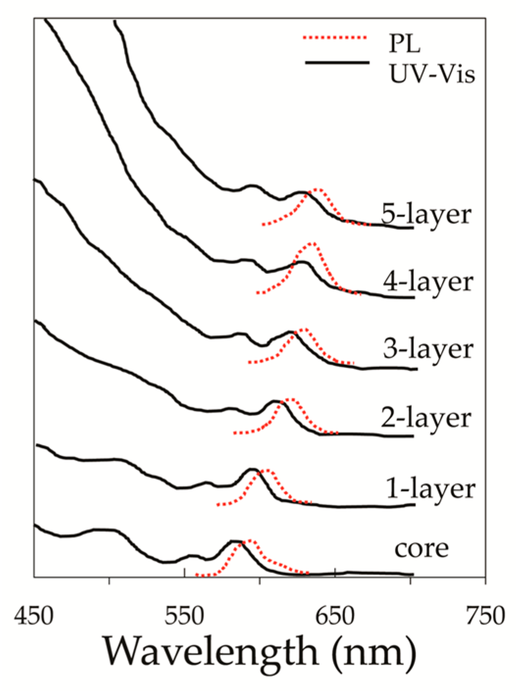
The phenomena of absorption and emission in type I core/shell QDs is mainly dependent on the core size and shell thickness. The advantage of using thicker shells is that both carriers (excited electrons and the holes) will be confined in the same Nano-crystal (core), which in-turn enhances the photoluminescence QY and increases the stokes shift that causes redshift of the PL emission [57]. The absorption in type I core/shell QDs is dominated by the thick shells, while the emission is dominated by the core size. The UV-Vis and PL emission of the CdSe/CdS core/shell QDs with different shell thicknesses were measured, as shown in Figure 7 [34]. The core diameter ranged from 2.3 to 3.9 nm and the QYs were above 50%. This type of CdSe/CdS QDs absorbs in the UV-Vis ranges of the solar spectrum and their absorption peaks increase with thicker shells and smaller core size. The PL emission also increases to higher wavelengths for thicker shells (Figure 7).
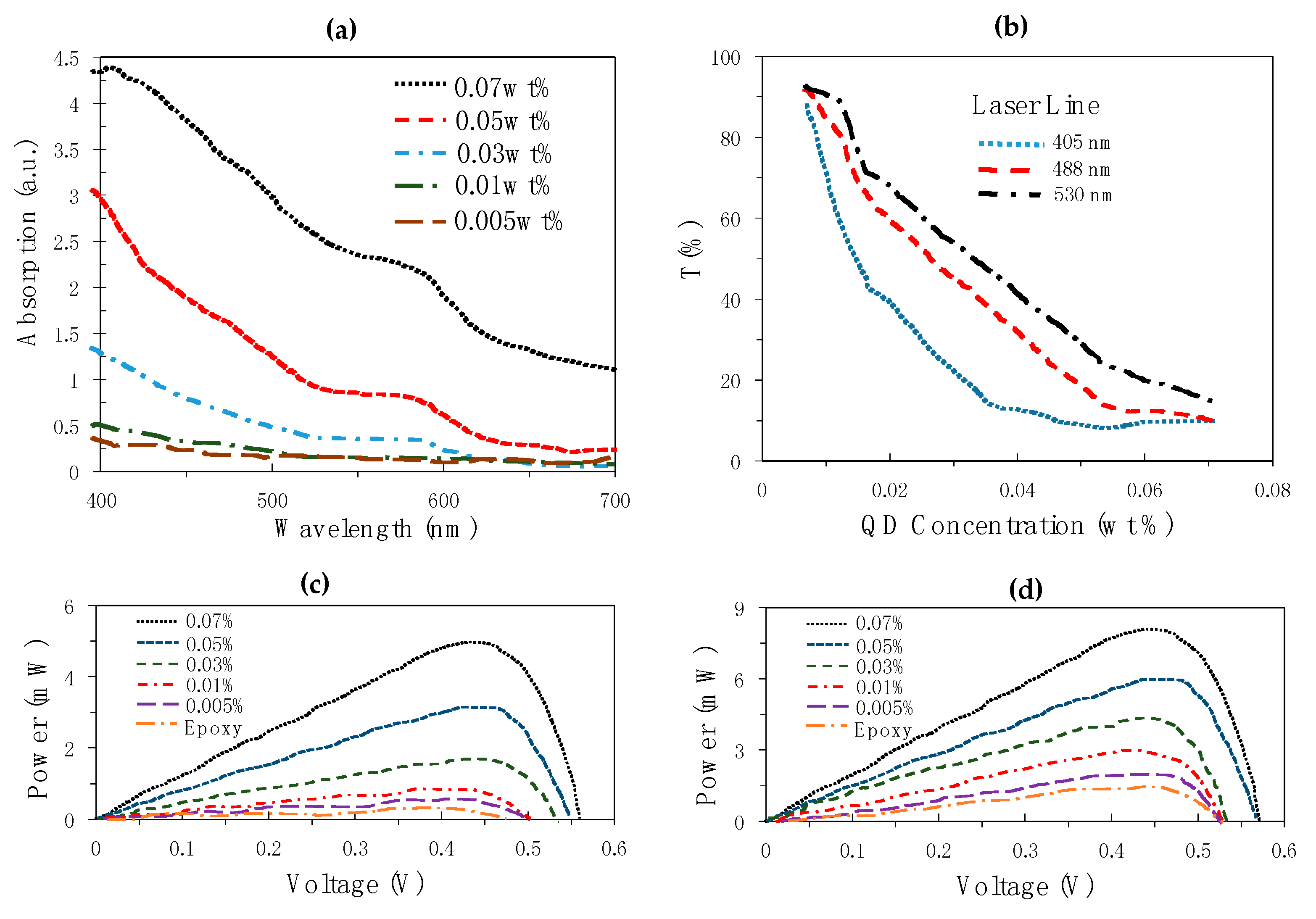
The concentration of type I core/shell QDs also affects their performance when used as QDs-LSC. Chandra at al. [58] optimized the doping concentration for type I CdSe/ZnS QD (as the dopant) with a band gap ranging from 2.14 eV at 27 °C to 2.16 eV at 100 °C doped in epoxy (as the host) to form QDSC. Five samples on 6.0 × 4.0 × 0.2 cm plates were fabricated and coated with 0.005, 0.01, 0.03, 0.05, 0.07 wt% by a drop casting technique. The absorption spectra of QDSC plates with varying QDs’ concentrations are illustrated in Figure 8a. This figure shows that increasing the concentration of QDs increases absorption intensity. The emission transport properties of the QDs in this research were also examined using varying optical-path lengths using laser line 405, 488, and 532nm, and white color using a cutoff wavelength of 600 nm. It was proven that increasing the concentration reduces the transparency of the glass regardless of the optical path length (Figure 8b). This reduces the amount of daylighting entering a space, and will also affect occupants’ visual comfort and satisfaction. The electrical output in terms of power production was collected via Si PV cells at the edge of the system with and without backing reflectors. The power output increased with higher QDs’ concentrations (for both with and without backing reflectors) (Figure 8c,d). The optimum QDs’ concentration that gave better optical characteristics for the 6.0 × 4.0 × 0.2 cm plate was 0.03 wt%, while that which gave the maximum power output was 0.07 wt%. The emission was lost before reaching the edge of the transparent material for 70% of QDs using optical path-lengths >20 mm, and thereby reduce the efficiency of the system. It was recommended to use the electrical and optical output together to optimize the size of the LSC and the QDs concentration.
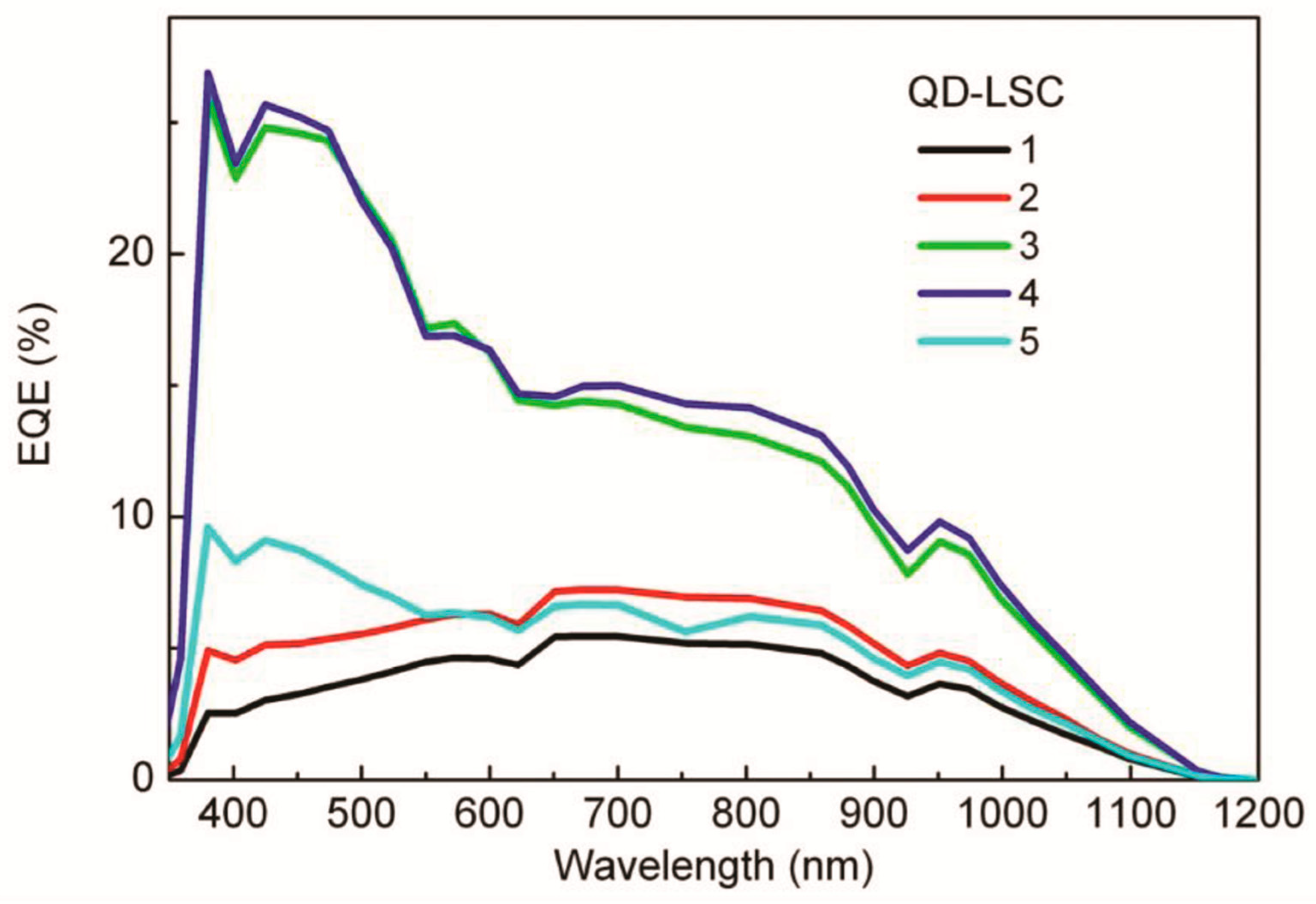
The effect of concentration on type I core/shell QDs was also investigated by Bomm et al. [59]. The study measured the electrical output and the PL QY of luminescent solar concentrators (LSCs) using different concentrations and UV-initiator of CdSe core/multi-shell quantum dots (QDs) (Figure 9a). The QDs with a diameter average of 6.77 ± 0.7 nm was doped in a transparent polymer matrix to form QDs-LSC with variable sizes up to 5.0 × 3.8 × 0.4 cm. Silicon solar cells (5.0 × 0.5 cm) were attached to one side of the QDs-LSC, while mirrors were attached to the other three sides as illustrated in Figure 9b. A diffused, white reflector was placed at the bottom of the QDs-LSC to help measure the spectral response of the system. The QDs absorbed about 31% of the solar spectrum between wavelengths 300–1100 nm. Five different QDs-LSCs were created with different QDs concentrations and UV-initiator to measure the PL QY and the current for each Si PV cell (Isc) (see Table 2). QDs concentration and UV-initiator were found to affect the efficiency of the system in various ways. Increasing the concentration of QDs reduced the PL QY, increased the absorption and PL intensity and increased the external quantum efficiency (EQE) at wavelengths where QDs absorb (<600 nm) (Figure 10). The external quantum efficiency (EQE) is the ratio of incident photon energy to the electrical energy produced by the PV cell. Another studied variable was the size of the LSC. The small sized QDs-LSC was found to produce higher photocurrent (PCE = 2.8%) and reduce the re-absorption phenomena of the photons. The study recommended that the absorption of the QDs should be higher, extended to NIR ranges and the reabsorption should be reduced by using QDs that exhibit large stokes-shifts.
Another way to resolve the limitation of the small stokes shift in type I core/shell QDs, while still maintain their high QY, is to add some ions to the semiconductors. Adding a small number of ions to type I core/shell QDs introduce localized excited states that enlarged stokes shift, due to the new doped ions. These doped ion QDs have high QYs and large stokes shifts, which encourages their fabrication as large-scale QDs-LSC. A previous study tried to fabricate a visibly transparent LSC by doping Mn2+ in ZnSe/ZnS core/shell QDs [60]. The size of the LSC was 2.5 × 7.5 × 0.42 cm, which corresponds to the G factor of 22. The G factor is the ratio of the surface area exposed to sunlight to the area of the edges that are coupled with the solar cells. The Mn2+ doped ZnSe/ZnS revealed a large stokes shift without any overlap between the absorption and emission spectrum and produced a semitransparent glass under visible light (Figure 11). The study also measured the internal quantum efficiency and found it to be 37% under UV excitation. Nevertheless, the absorption of these Mn2+ doped ZnSe/ZnS QDs did not utilize the full spectrum and was limited to the UV range. There are several advantages of QDs with doped ions over those without doped ions. The doped ions QDs are one dimensional that allow for the emission and at the same time block the reabsorption. They also enhance the QY and have small dimensions which reduce the losses caused by scattering [12,61]. Other types of doped ions, such as Cu2+ could be used to widen the absorption range of the solar spectrum [9,12,60].

3.1.2. LSC with Type II and Inverse Type II Core/Shell QDs

Instead of confining both carriers (excited electrons and holes) in one region, type II core/shell QDs spatially separate them into different regions. This enhances the ability of a shell to tune the wavelengths emission to wider ranges. The localization of carriers and energy offset between the core and the shell in type II core/shell QDs can be controlled via controlling the size of the core and the thickness of the shell. Whereas type II core/shell QDs exhibit large stokes shifts, they suffer from low QYs (0–10%) because some of the holes leak to the surface and cause scattering [62]. This shortcoming could be overcome by using inverse type II core/shell QDs, where one of the carriers is delocalized in the core/shell structure, and the other is confined within the core preventing any leakage to the surface.
The advantage of using type II and inverse type II core/shell QDs is that they are excellent emitters for NIR wavelengths. Restricting the absorption of the QDs to UV-Vis ranges only (wavelengths less than 500 nm), such as the case when using type I core/shell QDs, limits the utilization of the full spectrum, and around 60% of the solar spectrum becomes unabsorbed. Nonetheless, expanding the emission ranges of QDs to NIR wavelengths enables the fabrication of colorless and semitransparent LSC. It also enhances the external quantum efficiency (EQE) of the system, since the NIR waves emitted by QDs will be optimum for coupling with a typical Si PV cells that collect photons and convert them to electricity.
PbS and PbSe QDs have a low band gap and tunable emission near the NIR region [63,64,65]. They also have a high absorption coefficient of 1–5 × 105 cm−1 and hence could be ideally used as QDSCs. Shcherbatyuk et al. [4] tested the QDs-LSC system using PbS QDs in an LSC plate that is 4.5 × 1.2 × 0.4 cm in dimensions. They attached Si PV cells at the edge of one side of the LSC, with an active area of 0.36 cm2 (Figure 12a) to compare between the spectra of CdSe and PbS QDs when used as a core. Whereas PbS QDs have high stokes shift that is much greater than that of CdSe, the solution concentrations that contains PbS needs to be 10% more than that of CdSe to achieve the same absorption [4]. These high concentrations increase the reabsorption of photons by other QDs, which reduce the efficiency of the system and result in energy losses. It was found that the PbS LSCs generate around twice the photocurrent in silicon cells than the CdSe, and the optical efficiency was very high reaching around 12.6% (Figure 12b).
The power conversion efficiency (PCE) of the QDSC with PbS is usually less than 4% without coating or doping. It was found that when the PbS surface is coated with CdS to produce PbS-CdS co-sensitized solar cells, the PCE exceeds 4% [64]. Additionally, Park et al. have produced the highest PCE of 5.6% by doping Hg in the PbS solution [64]. To date, the PCE of the PbS QDSC do not reach expectation owing to many reasons, such as the high charge recombination and instability of PbS in the electrolyte owing to their slow excited electron transfer kinetics that affects the charge separation and collection. [63,66,67].

3.1.3. LSC with Type I-III-VI2 Core/Shell QDs

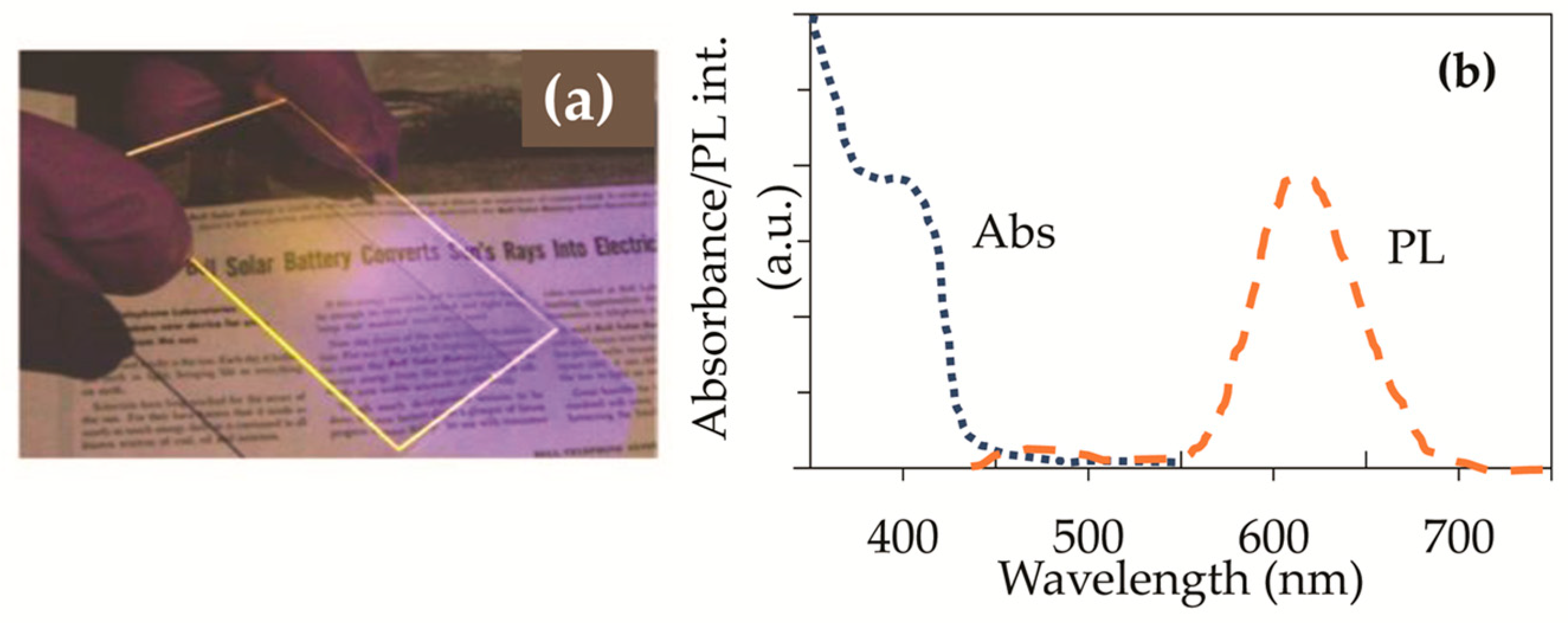
Type I-III-VI2 QDs have a neutral-density filter that does not cause disturbance to the perceived colors and thus could be integrated into the glazing system of any building (Skylights/windows). QDs of Type I–III–VI2 containing CuInSexS2–x were doped into photo-polymerized poly (lauryl methacrylate) to fabricate the first large-area concentrator [37]. CISeS QDs with an emission wavelength of 960 nm were coated with ZnS. An LSC slab with dimensions of 12 × 12 × 0.3 cm was illuminated with ultraviolet light at 365 nm and calibrated Si photodiodes were installed along the slab perimeter (Figure 13a). No reflector at the bottom of the LSC was used in order to represent a real window application. An overlap between the absorption and emission spectra was observed, which suggests a potential for losing energy, due to reabsorption (Figure 13b). The large stokes shift in this type is mainly due to the hole-like defect that causes inter-gap emission. A solar simulator (Figure 13c) was used to measure the optical power conversion efficiency of the LSC for two samples; one absorbs 10% (0.3 wt% QDs) referred to as LSC10, and the other absorbs 20% (0.5 wt% QDs) referred to as LSC20 (Figure 13d,e). The optical power conversion for the LSC20 (3.27%) was greater than that for the LSC10 (1.02%) considering that both samples exhibited a high degree of transparency across the visible spectrum. The study also investigated whether the LSC10 and LSC20 cause significant distortion to outdoor views. This was done qualitatively by taking a photograph of a color-rich scene once without any filtering, second with LSC10 plate in front of the camera lens, and a third with LSC20 plate in front of the camera lens (see Figure 13f–h). This qualitative analysis indicated that neither of the LSC introduced apparent color distortions, only a small effect is noticed for the denser LSC20. To further compare the color appearance of the LSC produced in this study with other normal LSC, a colorimetry evaluation was conducted between the LSC20 and a device based on a Crs040 yellow organic dye that was fabricated to exhibit the same absorption percentage (20%) of the complete solar spectrum. This evaluation in the Munsell’s color atlas revealed that the color produced by the LSC20 was in the dark brownish range which is a typical coloring of neutral sunglass lenses, while that of the Crs040 yellow organic dye had a brilliant yellow color (Figure 13i). The color rendering index (CRI) of the two samples was also measured. It was found that the CRI for the LSC20 equals 91, which correspond to CIE color rendering group1A (the highest requirement for indoor illumination for applications like galleries, medical examination, and color mixing). On the other hand, the CRI for the Crs040_based LSC was 57 (CIE group 3), which is suitable at best to illuminate industries. This type of core/shell QDs overcomes some of the limitations in the organic dyes, including incomplete coverage of the solar spectrum and strong coloring of the LSC.
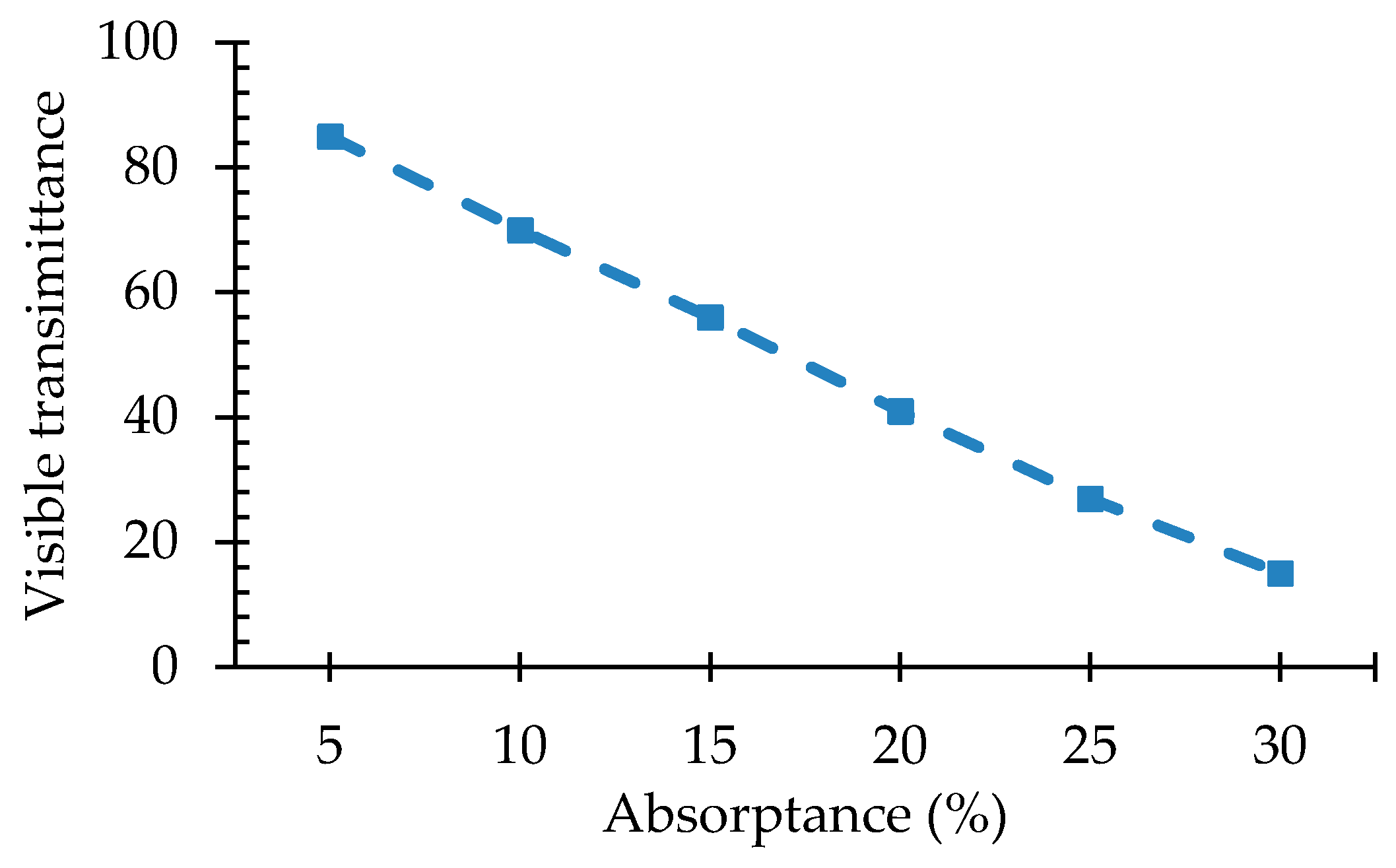
Controlling the concentration of I-III-VI2 QDs controls the degree of shading they can provide for indoor spaces [68]. Wu et al. created a tandem LSC device with a surface area of 230 cm2 that consists of two layers. The bottom had CuInSe2/ZnS that is characterized by its wide absorption spectrum and emission at 805 nm. This layer enabled the absorption of sunlight up to the NIR ranges. Wu et al. [68] showed that as the concentration of CuInSe2/ZnS increases, the visible transmittance of the transparent material decreases (from 85.5 % to 16.8 %), and at the same time the sunlight absorption of the solar spectrum increases from 5% to 30 % (Figure 14). CuInSexS2 is a non-toxic material that reduces the reabsorption of photons and enlarges the coverage of the solar spectrum. This tandem system resulted in optical power efficiency of 6.4%, a PCE of 3.1%, and a reasonably visible transmittance of 23%. These features render them promising in producing electricity, as well as being transparent/semitransparent for glazing applications. The most crucial data from Section 3 are summarized in Table 3.

4. Building Integrated Applications of QDs

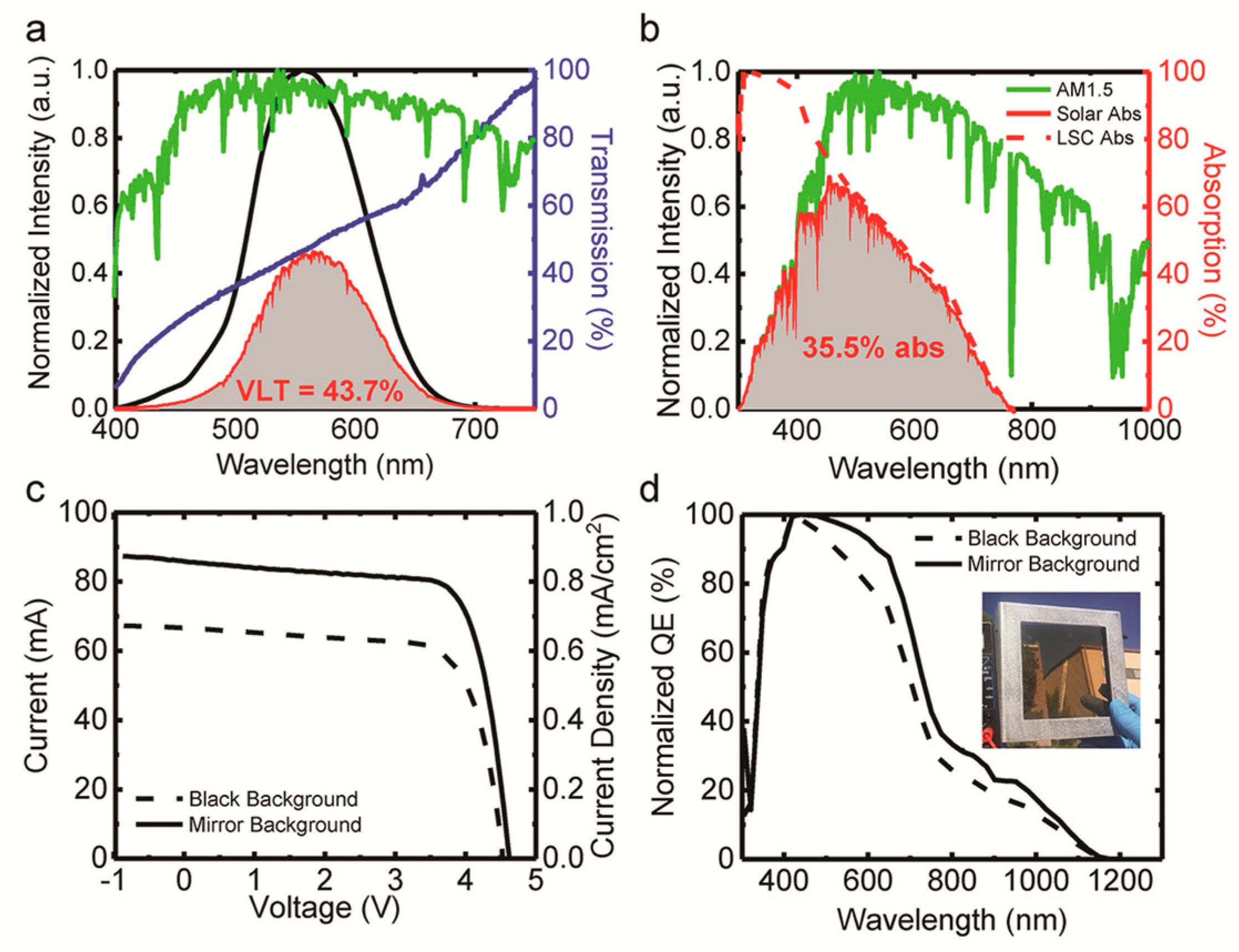
Bergren [73] developed LSC with NIR-emitting CuInS2/ZnS QDs to be integrated into buildings and harvest sunlight through building’s façade. CuInS2/ZnS were doped with a concentration of 0.4 % in a polymer interlayer between two sheets of low-iron float glass with dimensions of 10 × 10 cm. The investigation was done once with a reflective substrate below the LSC and another time without a reflective substrate below the LSC. Crystalline silicon (c-Si) solar cells were attached to one side of the LSC. This system absorbed 35.5% of the solar spectrum, while it transmits 43.7% of the visible light (Figure 15a,b). The PL peak emission was recorded at 862 nm. High optical efficacy of 8.1% was reported for the system. The PCE was measured with and without a reflective substrate below the LSC; and it was reported as 2.9% and 2.2%, respectively. The power production was also measured to be 30 W/m2, and 22 W/m2 (with and without the reflective substrate) (Figure 15c,d). This indicated that added a reflective substrate between the LSC increases the PCE and power production.
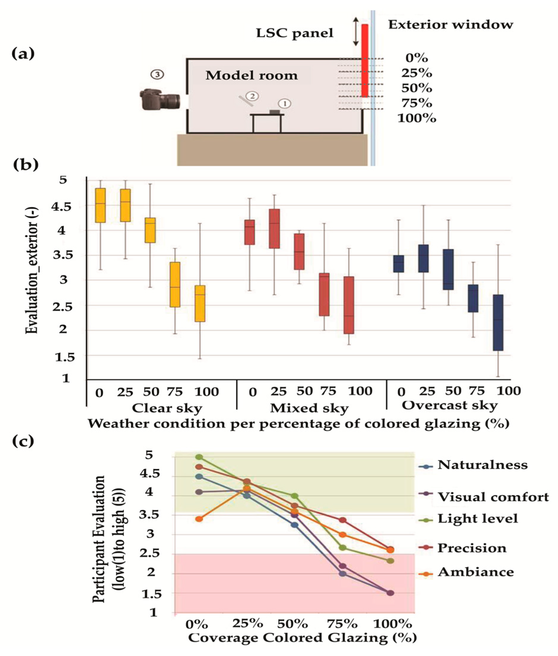
When QDs are integrated into windows/skylights, due to photoluminescence they can produce the desired coloring of the glass by stokes shift and produce electricity through LSC technology. Using QDs in windows/skylights has advantages of low cost, easy fabrication, highly efficient, controllable transparency, tunable shading degree, and flexible design [74,75,76]. Vossen et al. [77] studied the impact of a red LSC on the visual comfort and impression of volunteer participants in an office building. Three identical physical models were created for a 1.8 × 2.7 × 3.9 m3 room; two of them for participant evaluation and another for daylight measurements. A full-scale room was also used for participants’ evaluation. The reflectance of the interior surfaces was 90% for walls and ceiling and 26% for the flooring. The models and the full-scale room were located on the second floor of vertigo building at the Eindhoven University of Technology and had windows towards the true west direction. Each model had a sliding glass doped with Red 305 dye, which was used to adjust the percentage of the red colored LSC glass to 0%, 25%, 50%, 75%, and 100% (Figure 16a). The experiment was conducted in the morning time from 9–19 September 2014. Questionnaires were distributed to 35 males and 19 females (all between 21 and 28 years old) to evaluate the lighting conditions inside the office. Participants were asked to look at the objects in the room, conduct a reading task, and enjoy the outdoor view for 30 s. In one of the three models, the interior horizontal illuminance and the exterior vertical illuminance were measured using lux-meter while each participant evaluated the lighting conditions in the other models. The study also measured the interior spectral irradiance using a spectrometer and evaluated the color-rendering index and correlated color temperature. It was found that as the percentage of the LSC-colored glass increased, several effects happened: The average illuminance levels on the desk plane decreased, the positive evaluation of participants decreased, the average correlated color temperature (CCT) changed from cold to warm, and the color rendering index (CRI) decreased (Figure 16b). The study also tested the effect of the sky conditions (clear, mixed, and overcast sky), and found a significant difference between the weather conditions when evaluating the outdoor view. The 25% LSC coverage area lead to the best evaluation of the outdoor view (Figure 16c). The survey results showed that the most preferable LSC coverage for exterior views was 25%; and the most preferable for interior views was 0% to 25%, due to warmer colors. The study also showed that people are willing to accept more percentage of colored glass when they are aware of the importance of LSC in generating electricity.
TM2 halide materials were fabricated and characterized for their emission and absorption spectrum exhibiting a narrow gap between the emission and absorption. The narrow gap indicated lower self absorption losses that offer promise for the LSC based power generators. The TM2+ materials were tested as transparent PV windows, as shown in Figure 17. The novel PV produced up to four times power compared to the LSC windows fabricated out of organic dies. However, the challenge of producing LSC waveguide for such breakthrough windows remains unsolved and requires a significant amount of research [78].
The LSC based Smart Windows were developed by ENI and Politecnico di Milano and integrated into building as an active element in the buildings. The windows provided a multifunctional contribution in terms of energy saving through dynamic solar control and renewable energy production. It was observed that, although the power savings were limited, the smart windows relied on its own produced energy and provided an excellent control to the indoor environment, which otherwise is challenging in such buildings under all weather conditions with the most favorable integration scenario. The developed window was assessed in the built environment from a visual comfort point of view and its rendering indexed was determined. It was concluded that in the overcast sky conditions, such windows complied with the European Standards; yet, in the direct sun conditions some discomfort was observed. It was stressed to further research the topic to come up with better visual comfort of such windows in all sort of sky conditions [79].

5. Conclusions

The paper reviewed the various properties and types of core-shell QDs that are integrated into smart building glazing for the purpose of enhancing the indoor visual environment and energy production. The review discussed the effect of different variables (e.g., types of the QDs, core sizes, shell thicknesses, and concentrations of the QDs) on the overall efficiency of the system; and demonstrated how the solar absorption/emission phenomena can be manipulated in order to control the coloring of the emitted light, the transparency of the glass, the degree of shading, and the rate of power production. The main highlights of this paper can be summarized, as follow:
  • Increasing the shell thickness and reducing the core size helps to enhance the optical properties of all types of core-shell QDs by widening their absorption and emission spectrum;
  • Type II, inverse Type II, and type I-III-VI2 are preferred over type I because of their NIR emissions that can reach up to 800 nm; which can assist in utilizing the full solar spectrum;
  • Improving the properties of core-shell QDs, such as having large stokes shift, better stability and QY, and wider absorption could be achieved via adding a number of ions to any type of the core-shell QDs;
  • While increasing the concentration has the advantage of enhancing the power production of the LSC technology, it also leads to some disadvantages: It reduces the number of photons reaching the edge of the system, it reduces the transparency of the material and it increases the chances of re-absorption thus leading to energy losses;
  • While the inverse Type II has the advantage of being an excellent emitter of NIR emissions, it requires high concentrations to absorb a wide range of the solar spectrum. This high concentration causes re-absorptions of photons, reduces the electricity production of the system, and reduces the transparency of the LSC;
  • Type I-II-VI2 are non-toxic materials that have low manufacture cost, neutral-density filter, high coverage of the solar spectrum, and low recombination of photons; which make them very suitable to enhance the power performance, the visibility, and the esthetic appearance on buildings’ facades (windows/skylights);
  • It is crucial to consider both the optical characteristics and the electrical output when optimizing the size and the concentration of the QD in the QD-LSC technology.
Despite the huge advantages of the integrated QDs into the glazing of buildings, these systems still face some challenges, such as the charge re-combination, the reduced emission, and the scattering that impedes a widespread adaptation of the technology. Additionally, to date, scaling the sizes of QD-LSC is a major challenge of this technology that requires further breakthroughs.

Author Contributions

Proposing the idea, K.A.A.-S.; Original draft preparation, A.R.A.; Supervision, K.A.A.-S. and A.H.; Review and Editing, K.A.A.-S., and A.H.; Revision, A.R.A., K.A.A.-S., and A.H.; project administration, K.A.A.-S.; funding acquisition, K.A.A.-S.

Funding

This research was funded by the Emirates Centre for Energy and Environment Research (ECEER) at UAE University, Grant Number 31R108.

Conflicts of Interest

The authors declare no conflict of interest.

Nomenclature

QDsQuantum dots
UVUltraviolet radiations
VisVisible light
NIRNear infrared radiations
TIRTotal internal reflection
BIPVBuilding integrated photovoltaic
QYQuantum yield
PLThe photoluminescence
LSCLuminescent solar concentrators
QDs-LSCQuantum dots luminescent solar concentrators
Si PV Silicon photovoltaic
QDSCQuantum dots solar concentrators
EQEThe external quantum efficiency of the solar cells
PCEThe power conversion efficiency of the solar cells
CRIThe color rendering index
CCTCorrelated color temperature
ZbA zinc blende phase CdS
WzA wurtzite CdS shell
ECBEnergy in the conduction band
EVBEnergy in the valence band
EgEnergy gap
eVUnit of energy
a.u.Unit of absorbance
TTransmission
QEQuantum efficiency

References

  1. Carmody, J.; Selkowitz, S.; Lee, E.; Arasteh, D.; Willmert, T. Window System for High-Performance Buildings, 1st ed.; W. W. Norton & Company: New York, NY, USA, 2004. [Google Scholar]
  2. Selkowitz, S.; Aschehoug, O.; Lee, E.S. Advanced interactive facades-critical elements for future green buildings? In Proceedings of the GreenBuild, the Annual USGBC International Conference and Expo, Pittsburgh, PA, USA, 12–14 November 2003. [Google Scholar]
  3. Debije, M.G.; Verbunt, P.P.C. Thirty years of luminescent solar concentrator research: Solar energy for the built environment. Adv. Energy Mater. 2012, 2, 12–35. [Google Scholar] [CrossRef]
  4. Shcherbatyuk, G.V.; Inman, R.H.; Wang, C.; Winston, R.; Ghosh, S. Viability of using near infrared PbS quantum dots as active materials in luminescent solar concentrators. Appl. Phys. Lett. 2010, 96, 191901. [Google Scholar] [CrossRef]
  5. Regulacio, M.D.; Han, M.-Y. Composition-tunable alloyed B1semiconductor nanocrystals. Acc. Chem. Res. 2010, 43, 621–630. [Google Scholar] [CrossRef] [PubMed]
  6. Zhao, H.; Benetti, D.; Jin, L.; Zhou, Y.; Rosei, F.; Vomiero, A. Absorption Enhancement in “Giant” Core/Alloyed-Shell Quantum Dots for Luminescent Solar Concentrator. Small 2016, 12, 5354–5365. [Google Scholar] [CrossRef] [PubMed]
  7. Shao, H.; Bai, X.; Cui, H.; Pan, G.; Jing, P.; Qu, S.; Zhu, J.; Zhai, Y.; Dong, B.; Song, H. White light emission in Bi3+/Mn2+ ion co-doped CsPbCl3 perovskite nanocrystals. Nanoscale 2018, 10, 1023–1029. [Google Scholar] [CrossRef] [PubMed]
  8. Renuga, V.; Manikandan, A. Influence of Mn2+ ions on both core/shell of CuInS2/ZnS nanocrystals. Mater. Res. Bull. 2018, 98, 265–274. [Google Scholar]
  9. Levchuk, I.; Würth, C.; Krause, F.; Osvet, A.; Batentschuk, M.; Resch-Genger, U.; Kolbeck, C.; Herre, P.; Steinrück, H.P.; Peukert, W. Industrially scalable and cost-effective Mn 2+ doped Zn x Cd 1− x S/ZnS nanocrystals with 70% photoluminescence quantum yield, as efficient down-shifting materials in photovoltaics. Energy Environ. Sci. 2016, 9, 1083–1094. [Google Scholar] [CrossRef]
  10. Goetzberger, A.; Wittwer, V. Fluorescent planar collector-concentrators: A review. Sol. Cells 1981, 4, 3–23. [Google Scholar] [CrossRef]
  11. Wittwer, V.; Heidler, K.; Zastrow, A.; Goetzberger, A. Theory of fluorescent planar concentrators and experimental results. J. Lumin. 1981, 24, 873–876. [Google Scholar] [CrossRef]
  12. Bradshaw, L.R.; Knowles, K.E.; McDowall, S.; Gamelin, D.R. Nanocrystals for luminescent solar concentrators. Nano Lett. 2015, 15, 1315–1323. [Google Scholar] [CrossRef] [PubMed]
  13. Li, M.; Wang, Q.; Shi, X.; Hornak, L.A.; Wu, N. Detection of mercury (II) by quantum dot/DNA/gold nanoparticle ensemble based nanosensor via nanometal surface energy transfer. Anal. Chem. 2011, 83, 7061–7065. [Google Scholar] [CrossRef] [PubMed]
  14. Zhao, H.; Liang, H.; Gonfa, B.A.; Chaker, M.; Ozaki, T.; Tijssen, P.; Vidal, F.; Ma, D. Investigating photoinduced charge transfer in double-and single-emission PbS@ CdS core@ shell quantum dots. Nanoscale 2014, 6, 215–225. [Google Scholar] [CrossRef] [PubMed]
  15. Tang, J.; Kemp, K.W.; Hoogland, S.; Jeong, K.S.; Liu, H.; Levina, L.; Furukawa, M.; Wang, X.; Debnath, R.; Cha, D. Colloidal-quantum-dot photovoltaics using atomic-ligand passivation. Nat. Mater. 2011, 10, 765. [Google Scholar] [CrossRef] [PubMed]
  16. Nozik, A.J.; Beard, M.C.; Luther, J.M.; Law, M.; Ellingson, R.J.; Johnson, J.C. Semiconductor quantum dots and quantum dot arrays and applications of multiple exciton generation to third-generation photovoltaic solar cells. Chem. Rev. 2010, 110, 6873–6890. [Google Scholar] [CrossRef] [PubMed]
  17. Sambur, J.B.; Novet, T.; Parkinson, B.A. Multiple exciton collection in a sensitized photovoltaic system. Science 2010, 330, 63–66. [Google Scholar] [CrossRef] [PubMed]
  18. Zhao, H.; Chaker, M.; Ma, D. Effect of CdS shell thickness on the optical properties of water-soluble, amphiphilic polymer-encapsulated PbS/CdS core/shell quantum dots. J. Mater. Chem. 2011, 21, 17483–17491. [Google Scholar] [CrossRef]
  19. Lambert, K.; Geyter, B.D.; Moreels, I.; Hens, Z. PbTe|CdTe core|shell particles by cation exchange, a HR-TEM study. Chem. Mater. 2009, 21, 778–780. [Google Scholar] [CrossRef]
  20. Huang, K.; Demadrille, R.; Silly, M.G.; Sirotti, F.; Reiss, P.; Renault, O. Internal structure of InP/ZnS nanocrystals unraveled by high-resolution soft X-ray photoelectron spectroscopy. ACS Nano 2010, 4, 4799–4805. [Google Scholar] [CrossRef] [PubMed]
  21. Jin, X.; Bai, J.; Gu, X.; Chang, C.; Shen, H.; Zhang, Q.; Li, F.; Chen, Z.; Li, Q. Efficient light-emitting diodes based on reverse type-I quantum dots. Opt. Mater. Express 2017, 7, 4395–4407. [Google Scholar] [CrossRef]
  22. Vasudevan, D.; Gaddam, R.R.; Trinchi, A.; Cole, I. Core-shell quantum dots: Properties and Applications. J. Alloys Compd. 2015, 636, 395–404. [Google Scholar] [CrossRef]
  23. Zhu, J.; Wang, S.-N.; Li, J.-J.; Zhao, J.-W. The effect of core size on the fluorescence emission properties of CdTe@ CdS core@ shell quantum dots. J. Lumin. 2018, 199, 216–224. [Google Scholar] [CrossRef]
  24. Chuang, C.-H.; Lo, S.S.; Scholes, G.D.; Burda, C. Charge separation and recombination in CdTe/CdSe core/shell nanocrystals as a function of shell coverage: Probing the onset of the quasi type-II regime. J. Phys. Chem. Lett. 2010, 1, 2530–2535. [Google Scholar] [CrossRef]
  25. Dabbousi, B.O.; Rodriguez-Viejo, J.; Mikulec, F.V.; Heine, J.R.; Mattoussi, H.; Ober, R.; Jensen, K.F.; Bawendi, M.G. (CdSe) ZnS core-shell quantum dots: Synthesis and characterization of a size series of highly luminescent nanocrystallites. J. Phys. Chem. B 1997, 101, 9463–9475. [Google Scholar] [CrossRef]
  26. Pal, B.N.; Ghosh, Y.; Brovelli, S.; Laocharoensuk, R.; Klimov, V.I.; Hollingsworth, J.A.; Htoon, H. ‘Giant’CdSe/CdS core/shell nanocrystal quantum dots as efficient electroluminescent materials: Strong influence of shell thickness on light-emitting diode performance. Nano Lett. 2011, 12, 331–336. [Google Scholar] [CrossRef] [PubMed]
  27. Basu, K.; Zhang, H.; Zhao, H.; Bhattacharya, S.; Navarro-Pardo, F.; Datta, P.K.; Jin, L.; Sun, S.; Vetrone, F.; Rosei, F. Highly stable photoelectrochemical cells for hydrogen production using a SnO 2–TiO 2/quantum dot heterostructured photoanode. Nanoscale 2018, 10, 15273–15284. [Google Scholar] [CrossRef] [PubMed]
  28. Bakhoda, S.; Assadi, M.K.; Ahmadi_Kandjani, S.; Al_Kayiem, H.H.; Bhat, A.H. Application of Quantum Dot nanocrystal in Luminescent solar concentrators. In Proceedings of the 3rd International Conference on Mechanical, Manufacturing and Process Plant Engineering (ICMMPE 2017), Batu Ferringhi, Penang, Malaysia, 22–23 November 2017; p. 012022. [Google Scholar]
  29. Ramanery, F.P.; Mansur, A.A.P.; Mansur, H.S. Synthesis and characterization of water-dispersed CdSe/CdS core-shell quantum dots prepared via layer-by-layer method capped with carboxylic-functionalized poly (vinyl alcohol). Mater. Res. 2014, 17, 133–140. [Google Scholar] [CrossRef]
  30. Pan, Z.; Zhang, H.; Cheng, K.; Hou, Y.; Hua, J.; Zhong, X. Highly efficient inverted type-I CdS/CdSe core/shell structure QD-sensitized solar cells. ACS Nano 2012, 6, 3982–3991. [Google Scholar] [CrossRef] [PubMed]
  31. Kim, S.; Park, J.; Kim, T.; Jang, E.; Jun, S.; Jang, H.; Kim, B.; Kim, S.W. Reverse Type-I ZnSe/InP/ZnS Core/Shell/Shell Nanocrystals: Cadmium-Free Quantum Dots for Visible Luminescence. Small 2011, 7, 70–73. [Google Scholar] [CrossRef] [PubMed]
  32. Kim, S.; Fisher, B.; Eisler, H.-J.; Bawendi, M. Type-II quantum dots: CdTe/CdSe (core/shell) and CdSe/ZnTe (core/shell) heterostructures. J. Am. Chem. Soc. 2003, 125, 11466–11467. [Google Scholar] [CrossRef] [PubMed]
  33. Wu, K.; Song, N.; Liu, Z.; Zhu, H.; Rodríguez-Córdoba, W.; Lian, T. Interfacial charge separation and recombination in InP and quasi-type II InP/CdS core/shell quantum dot-molecular acceptor complexes. J. Phys. Chem. A 2013, 117, 7561–7570. [Google Scholar] [CrossRef] [PubMed]
  34. Reiss, P.; Protiere, M.; Li, L. Core/shell semiconductor nanocrystals. Small 2009, 5, 154–168. [Google Scholar] [CrossRef] [PubMed]
  35. Berends, A.C.; Rabouw, F.T.; Spoor, F.C.M.; Bladt, E.; Grozema, F.C.; Houtepen, A.J.; Siebbeles, L.D.A.; de Mello Donegá, C. Radiative and nonradiative recombination in CuInS2 nanocrystals and CuInS2-based core/shell nanocrystals. J. Phys. Chem. Lett. 2016, 7, 3503–3509. [Google Scholar] [CrossRef] [PubMed]
  36. Rice, W.D.; McDaniel, H.; Klimov, V.I.; Crooker, S.A. Magneto-optical properties of CuInS2 nanocrystals. J. Phys. Chem. Lett. 2014, 5, 4105–4109. [Google Scholar] [CrossRef] [PubMed]
  37. Meinardi, F.; McDaniel, H.; Carulli, F.; Colombo, A.; Velizhanin, K.A.; Makarov, N.S.; Simonutti, R.; Klimov, V.I.; Brovelli, S. Highly efficient large-area colourless luminescent solar concentrators using heavy-metal-free colloidal quantum dots. Nat. Nanotechnol. 2015, 10, 878–885. [Google Scholar] [CrossRef] [PubMed]
  38. Schuster, M.; Sisterhenn, P.; Graf, L.; Wellmann, P.J. Processing and Characterization of Vacuum-Free CuInSe2 Thin Films from Nanoparticle-Precursors using Novel Temperature Treatment Techniques. J. Nanopart. Res. 2018, 2, 4. [Google Scholar]
  39. Erickson, C.S. Doped Quantum Dot Luminescent Solar Concentrators. Master’s Thesis, Western Washington University, Bellingham, WA, USA, 2014. [Google Scholar]
  40. Tanabe, K. A review of ultrahigh efficiency III-V semiconductor compound solar cells: Multijunction tandem, lower dimensional, photonic up/down conversion and plasmonic nanometallic structures. Energies 2009, 2, 504–530. [Google Scholar] [CrossRef]
  41. Jin, L.; AlOtaibi, B.; Benetti, D.; Li, S.; Zhao, H.; Mi, Z.; Vomiero, A.; Rosei, F. Near-Infrared Colloidal Quantum Dots for Efficient and Durable Photoelectrochemical Solar-Driven Hydrogen Production. Adv. Sci. 2016, 3, 1500345. [Google Scholar] [CrossRef] [PubMed]
  42. Zhao, H.; Sirigu, G.; Parisini, A.; Camellini, A.; Nicotra, G.; Rosei, F.; Morandi, V.; Zavelani-Rossi, M.; Vomiero, A. Dual emission in asymmetric “giant” PbS/CdS/CdS core/shell/shell quantum dots. Nanoscale 2016, 8, 4217–4226. [Google Scholar] [CrossRef] [PubMed] [Green Version]
  43. Zhou, Y.; Benetti, D.; Fan, Z.; Zhao, H.; Ma, D.; Govorov, A.O.; Vomiero, A.; Rosei, F. Near infrared, highly efficient luminescent solar concentrators. Adv. Energy Mater. 2016, 6, 1501913. [Google Scholar] [CrossRef]
  44. Hines, M.A.; Scholes, G.D. Colloidal PbS nanocrystals with size-tunable near-infrared emission: Observation of post-synthesis self-narrowing of the particle size distribution. Adv. Mater. 2003, 15, 1844–1849. [Google Scholar] [CrossRef]
  45. Zhao, H.; Chaker, M.; Wu, N.; Ma, D. Towards controlled synthesis and better understanding of highly luminescent PbS/CdS core/shell quantum dots. J. Mater. Chem. 2011, 21, 8898–8904. [Google Scholar] [CrossRef]
  46. Batchelder, J.S.; Zewai, A.H.; Cole, T. Luminescent solar concentrators. 1: Theory of operation and techniques for performance evaluation. Appl. Opt. 1979, 18, 3090–3110. [Google Scholar] [CrossRef] [PubMed]
  47. Richards, B.S. Enhancing the performance of silicon solar cells via the application of passive luminescence conversion layers. Sol. Energy Mater. Sol. Cells 2006, 90, 2329–2337. [Google Scholar] [CrossRef]
  48. Richards, B.S.; Shalav, A.; Corkish, R.P. A low escape-cone-loss luminescent solar concentrator. In Proceedings of the 19th European Photovoltaic Solar Energy Conference, Paris, France, 7–11 June 2004; pp. 113–116. [Google Scholar]
  49. McIntosh, K.R.; Yamada, N.; Richards, B.S. Theoretical comparison of cylindrical and square-planar luminescent solar concentrators. Appl. Phys. B 2007, 88, 285–290. [Google Scholar] [CrossRef]
  50. Bornstein, J.G. Luminescent Solar Concentrator Daylighting. In Proceedings of the 28th Annual Technical Symposium, San Diego, CA, USA, 27 July–1 August 2014; p. 8. [Google Scholar]
  51. Earp, A.A.; Smith, G.B.; Franklin, J.; Swift, P. Optimisation of a three-colour luminescent solar concentrator daylighting system. Sol. Energy Mater. Sol. Cells 2004, 84, 411–426. [Google Scholar] [CrossRef]
  52. Wilson, L.R. Luminescent Solar Concentrators: A Study of Optical Properties, Re-Absorption and Device Optimisation. Ph.D. Thesis, Herior-Watt University Edingurgh, Edingurgh, UK, 2010. [Google Scholar]
  53. Zhang, Q.; Guo, X.; Huang, X.; Huang, S.; Li, D.; Luo, Y.; Shen, Q.; Toyoda, T.; Meng, Q. Highly efficient CdS/CdSe-sensitized solar cells controlled by the structural properties of compact porous TiO2 photoelectrodes. Phys. Chem. Chem. Phys. 2011, 13, 4659–4667. [Google Scholar] [CrossRef] [PubMed]
  54. Yu, X.-Y.; Liao, J.-Y.; Qiu, K.-Q.; Kuang, D.-B.; Su, C.-Y. Dynamic study of highly efficient CdS/CdSe quantum dot-sensitized solar cells fabricated by electrodeposition. ACS Nano 2011, 5, 9494–9500. [Google Scholar] [CrossRef] [PubMed]
  55. Kongkanand, A.; Tvrdy, K.; Takechi, K.; Kuno, M.; Kamat, P.V. Quantum dot solar cells. Tuning photoresponse through size and shape control of CdSe− TiO2 architecture. J. Am. Chem. Soc. 2008, 130, 4007–4015. [Google Scholar] [CrossRef] [PubMed]
  56. Cossairt, B.M.; Owen, J.S. CdSe clusters: At the interface of small molecules and quantum dots. Chem. Mater. 2011, 23, 3114–3119. [Google Scholar] [CrossRef]
  57. Meinardi, F.; Colombo, A.; Velizhanin, K.A.; Simonutti, R.; Lorenzon, M.; Beverina, L.; Viswanatha, R.; Klimov, V.I.; Brovelli, S. Large-area luminescent solar concentrators based on ‘Stokes-shift-engineered’nanocrystals in a mass-polymerized PMMA matrix. Nat. Photonics 2014, 8, 392–399. [Google Scholar] [CrossRef]
  58. Chandra, S.; McCormack, S.J.; Kennedy, M.; Doran, J. Quantum dot solar concentrator: Optical transportation and doping concentration optimization. Sol. Energy 2015, 115, 552–561. [Google Scholar] [CrossRef]
  59. Bomm, J.; Büchtemann, A.; Chatten, A.J.; Bose, R.; Farrell, D.J.; Chan, N.L.A.; Xiao, Y.; Slooff, L.H.; Meyer, T.; Meyer, A. Fabrication and full characterization of state-of-the-art quantum dot luminescent solar concentrators. Sol. Energy Mater. Sol. Cells 2011, 95, 2087–2094. [Google Scholar] [CrossRef]
  60. Erickson, C.S.; Bradshaw, L.R.; McDowall, S.; Gilbertson, J.D.; Gamelin, D.R.; Patrick, D.L. Zero-reabsorption doped-nanocrystal luminescent solar concentrators. ACS Nano 2014, 8, 3461–3467. [Google Scholar] [CrossRef] [PubMed]
  61. Beaulac, R.; Archer, P.I.; Gamelin, D.R. Luminescence in colloidal Mn2+-doped semiconductor nanocrystals. J. Solid State Chem. 2008, 181, 1582–1589. [Google Scholar] [CrossRef]
  62. de Mello Donegá, C. Synthesis and properties of colloidal heteronanocrystals. Chem. Soc. Rev. 2011, 40, 1512–1546. [Google Scholar] [CrossRef] [PubMed] [Green Version]
  63. González-Pedro, V.; Sima, C.; Marzari, G.; Boix, P.P.; Giménez, S.; Shen, Q.; Dittrich, T.; Mora-Seró, I. High performance PbS Quantum Dot Sensitized Solar Cells exceeding 4% efficiency: The role of metal precursors in the electron injection and charge separation. Phys. Chem. Chem. Phys. 2013, 15, 13835–13843. [Google Scholar] [CrossRef] [PubMed]
  64. Lee, J.-W.; Son, D.-Y.; Ahn, T.K.; Shin, H.-W.; Kim, I.Y.; Hwang, S.-J.; Ko, M.J.; Sul, S.; Han, H.; Park, N.-G. Quantum-dot-sensitized solar cell with unprecedentedly high photocurrent. Sci. Rep. 2013, 3, 1050. [Google Scholar] [CrossRef] [PubMed]
  65. Pietryga, J.M.; Schaller, R.D.; Werder, D.; Stewart, M.H.; Klimov, V.I.; Hollingsworth, J.A. Pushing the band gap envelope: Mid-infrared emitting colloidal PbSe quantum dots. J. Am. Chem. Soc. 2004, 126, 11752–11753. [Google Scholar] [CrossRef] [PubMed]
  66. Lai, L.-H.; Protesescu, L.; Kovalenko, M.V.; Loi, M.A. Sensitized solar cells with colloidal PbS-CdS core-shell quantum dots. Phys. Chem. Chem. Phys. 2014, 16, 736–742. [Google Scholar] [CrossRef] [PubMed]
  67. Lee, H.; Leventis, H.C.; Moon, S.J.; Chen, P.; Ito, S.; Haque, S.A.; Torres, T.; Nüesch, F.; Geiger, T.; Zakeeruddin, S.M. PbS and CdS quantum dot-sensitized solid-state solar cells: “Old concepts, new results”. Adv. Funct. Mater. 2009, 19, 2735–2742. [Google Scholar] [CrossRef]
  68. Wu, K.; Li, H.; Klimov, V.I. Tandem luminescent solar concentrators based on engineered quantum dots. Nat. Photonics 2018, 12, 105–110. [Google Scholar] [CrossRef]
  69. Purcell-Milton, F.; Gun’ko, Y.K. Quantum dots for Luminescent Solar Concentrators. J. Mater. Chem. 2012, 22, 16687–16697. [Google Scholar] [CrossRef]
  70. Neo, D.C.J.; Cheng, C.; Stranks, S.D.; Fairclough, S.M.; Kim, J.S.; Kirkland, A.I.; Smith, J.M.; Snaith, H.J.; Assender, H.E.; Watt, A.A.R. Influence of shell thickness and surface passivation on PbS/CdS core/shell colloidal quantum dot solar cells. Chem. Mater. 2014, 26, 4004–4013. [Google Scholar] [CrossRef]
  71. Liu, M.; Voznyy, O.; Sabatini, R.; Pelayo Garcı’a de Arquer, F.; Munir, R.; Balawi, A.H.; Lan, X.; Fan, F.; Walters, G.; Kirmani, A.R.; et al. Hybrid organic-inorganic inks flatten the energy landscape in colloidal quant. Nat. Mater. 2017, 16, 258. [Google Scholar] [CrossRef] [PubMed]
  72. Du, J.; Du, Z.; Hu, J.-S.; Pan, Z.; Shen, Q.; Sung, J.; Long, D.; Dong, H.; Sun, L.; Zhong, X.; et al. Zn-Cu-In-Se quantum dot solar cells with a certified power conversion efficiency of 11.6%. J. Am. Chem. Soc. 2016, 138, 4201–4209. [Google Scholar] [CrossRef] [PubMed]
  73. Bergren, M.R.; Makarov, N.S.; Ramasamy, K.; Jackson, A.; Guglielmetti, R.; McDaniel, H. High-Performance CuInS2 Quantum Dot Laminated Glass Luminescent Solar Concentrators for Windows. ACS Energy Lett. 2018, 3, 520–525. [Google Scholar] [CrossRef]
  74. Li, C.; Chen, W.; Wu, D.; Quan, D.; Zhou, Z.; Hao, J.; Qin, J.; Li, Y.; He, Z.; Wang, K. Large stokes shift and high efficiency luminescent solar concentrator incorporated with CuInS2/ZnS quantum dots. Sci. Rep. 2015, 5, 17777. [Google Scholar] [CrossRef] [PubMed]
  75. Van Sark, W. Luminescent solar concentrators—A low cost photovoltaics alternative. Renew. Energy 2013, 49, 207–210. [Google Scholar] [CrossRef]
  76. Rowan, B.C.; Wilson, L.R.; Richards, B.S. Advanced Material Concepts for Luminescent Solar Concentrators. IEEE J. Sel. Top. Quant. Electron. 2008, 14, 1312–1322. [Google Scholar] [CrossRef]
  77. Vossen, F.M.; Aarts, M.P.J.; Debije, M.G. Visual performance of red luminescent solar concentrating windows in an office environment. Energy Build. 2016, 113, 123–132. [Google Scholar] [CrossRef]
  78. ten Kate, O.M.; Krämer, K.W.; van der Kolk, E. Efficient luminescent solar concentrators based on self-absorption free, Tm2+ doped halides. Sol. Energy Mater. Sol. Cells 2015, 140, 115–120. [Google Scholar] [CrossRef]
  79. Aste, N.; Tagliabue, L.C.; Palladino, P.; Testa, D. Integration of a luminescent solar concentrator: Effects on daylight, correlated color temperature, illuminance level and color rendering index. Sol. Energy 2015, 114, 174–182. [Google Scholar] [CrossRef]
Figure 1. Different types of core/shell quantum dots semiconductors (QDs).
Energies 12 01058 g001
Figure 2. Types of core/shell QDs based on band alignment [22].
Energies 12 01058 g002
Figure 3. The stokes shift is the difference between the peak of the absorption and the peak of the emission. Adapted from Reference [39].
Energies 12 01058 g003
Figure 4. (a) Absorbance spectra of CdSe core and different CdS shell thickness, (b) the color of optical emission at different wavelength according to the solar spectrum. Reprinted from Reference [29]; which is under Creative Commons Attribution License.
Energies 12 01058 g004
Figure 5. (a) The absorption and PL spectra of pure PbS (black) and PbS/CdS QDs (red). Reprinted from Reference [41]; which is under Creative Commons Attribution License. (b) Scheme of the energy level diagram of the PbS/CdS/CdS QDs. Adapted from Reference [42].
Energies 12 01058 g005
Figure 6. Schematic cross section of QD-luminescent solar concentrators (LSC).
Energies 12 01058 g006
Figure 7. The UV-Vis. and PL emission of the CdSe/CdS core/shell QDs with different shell thicknesses. Reprinted from Reference [34]. Copyright (2009) Wiley-VCH.
Energies 12 01058 g007
Figure 8. (a) absorption spectra of different CdSe/ZnS concentrations, (b) transmission percentage of the QDSC for different laser lines 405, 488, and 532, (c) the electrical power production for the Si PV cell attached to the QDSC with backing reflectors (the plate illuminated by light of 1 kW/m2, (d) the electrical power production for the Si PV cell attached to the QDSC without backing reflectors (the plate illuminated by light of 1 kW/m2. Adapted from Reference [58]. Copyright (2015) Elsevier.
Energies 12 01058 g008
Figure 9. (a) CdSe/CdS/CdZnS/ZnS core/multi-shell QDs and (b) illustration of QDs-LSC, Adapted from Reference [59]. Copyright (2011) Elsevier.
Energies 12 01058 g009
Figure 10. External quantum efficiency (EQE) spectra of five QDs-LSC doped with CdSe/CdS/CdZnS/ZnS. Reprinted from Reference [59]. Copyright (2011) Elsevier.
Energies 12 01058 g010
Figure 11. (a) Absorbance and PL spectra of Mn2+:ZnSe/ZnS QDs in an LSC device. (b) A device is seen under UV illumination. Reprinted with permission from Reference [60]. Copyright (2014) American Chemical Society.
Energies 12 01058 g011
Figure 12. (a) Absorption and emission curves for CdSe/ZnS, and PbS QDs, and emission curves for CdSe/ZnS, (b) The current production as a function of increasing the concentration for PbS and CdSe. Reprinted from Reference [4]. Copyright (2010) American Institute of Physics.
Energies 12 01058 g012
Figure 13. (a) (12 × 12 × 0.3) cm LSC was illuminated with ultraviolet light at 365 nm (b) absorption and emission spectrum, (c) a solar simulator (d,e) Photographs of large-area LSCs with dimensions of 12 × 12 × 0.3 cm comprising 0.3 wt% quantum dots (LSC10) and 0.5 wt% quantum dots (LSC20), (fh) photographs of a colorful scene taken with a Canon EOS 400D camera without using any filters (f), or withLSC10 (g) or LSC20 (h), (i) color coordinates in the CIEL color space of LSC20 compared to a device based on Crs040 yellow organic dye. Reprinted from Reference [37]. Copyright (2015) Nature Publishing Group.
Energies 12 01058 g013
Figure 14. The effect of increasing concentration on the absorptance and transmission of large area LSC with CuInSe2/ZnS core/shell QDs. Adapted from Reference [68].
Energies 12 01058 g014
Figure 15. (a) VLT of the transparent NIR-emitting CuInS2/ZnS QDs, (b) calculated solar absorption of NIR-emitting CuInS2/ZnS QDs, (c) I−V curves measured under AM1.5 illumination in a solar simulator for LSC with an absorbing black background (dashed line) and a mirrored background behind the window (solid line), (d) LSC to be applied to façade buildings. Reprinted with permission from Reference [73]. Copyright (2018) American Chemical Society.
Energies 12 01058 g015
Figure 16. (a) Schematic depicting the measurement setup of the model room. The red LSC plate could be positioned in five locations, and measurements made by a lux meter (1), spectrometer (2) and luminance camera (3), (b) Participant evaluation of the exterior view rated on a scale ranging from ‘1′ being most negative to ‘5′ being most positive as a function of LSC window coverage and weather conditions, (c) Participant evaluations based on median of the qualitative factors (ranging from most negative as 1 to most positive as 5 as a function of LSC coverage of the window. Reprinted from Reference [77]. Copyright (2016) Elsevier.
Energies 12 01058 g016
Figure 17. (a) The principle of operation of a semi-transparent, colorless luminescent solar concentrator in which the coating re-emits absorbed sunlight that is wave guided by total internal reflection in the glass-coating combination to the edges where solar cells convert the light to electric power. (b) Absorption and emission spectra of CaI2:TM2+ compared to state-of-the-art LSC materials like the organic dyes Red 305 and L170, CdSe quantum dots, and CdSe/CdS and CdTe/CdSe/ZnS type-II core-shell quantum dots. The percentages indicate the light harvesting efficiency of the LSC material. Reprinted from Reference [78]. Copyright (2015) Elsevier.
Energies 12 01058 g017
Table 1. Types of core/shell QDs based on band alignment.
ParameterType IInverse Type IType IIInverse Type II
Band gapThe band gap of the core is smaller than the band gap of the shell, as well as the band gap of the core falls within the band gap of the shell [18,19,20]The band gap of the core is greater than the band gap of the shell, as well as the band gap of the shell falls within band gap of the core [21]Valence band edge of the core is within the band gap of the shell or conduction band edge of the shell is within the band gap of the core [22,23]Conduction band edge of the core is within the band gap of the shell or valence band edge of the shell is within the band gap of the core [24]
Excited electrons/holes positionsExcited electrons and holes are completely confined in the core region [25]The excited electrons and holes are completely or partially confined in the shell based on the thickness of the shell.One charge carrier either excited electron or hole is confined to the core, while the other is mostly confined to the shellOne of the excited electrons or the holes are delocalized in the core/shell structure, and the other one is confined within the core.
Quantum yield (QY)Higher QY and long-term stability [25,26]Lower QY and poor stabilityLower QY and poor stability [27]Relatively higher QY and fair stability
Stokes shiftSmallSignificantly large [21]Large [28]Large and tunable via controlling the size of the core and thickness of the shell
Average absorption range(400–500) nm [29](400–500) nm [30,31](600–800) nm [23,32](300–1600) nm [33]
Average emission range(430–600) nm [34](400–700) nm [34](700–1000) nm [34](700–1000) nm [34]
LimitationsThe shell can trap charge carriers which leads to reduced fluorescence QYBoth the excited electrons and holes may leak to the surfaceOne of the excited electrons or hole leak to the surfaceThe excited electron or hole can be absorbed leading to reduced excited decay time one carrier is mostly confined to the core, while the other is mostly confined to the shell
Construct/materials
  • CdSe/ZnS
  • CdSe/CdS
  • CdS/ZnS
  • CdS/HgS
  • CdS/CdSe
  • ZnSe/CdSe
  • CdTe/CdSe
  • CdSe/ZnTe
  • CdSe/ZnSe
  • InP/CdS
  • PbS/CdS
Table 2. The concentration of QDs and UV initiator in five QD-LSC in Boom’s study. Adapted from Reference [59].
QDs-LSC NumberConcentration QDs (µmol/L)Concentration UV-Initiator (wt%)QY (%)Isc Total (mA)Dimensions (L × W) cm (h = 4 cm)Isc per Cell Area (mA/cm2)
10.110.5933.150 × 3.821.8
20.110.2518.125.53.2 × 3.319.3
30.670.145.490.44.0 × 3.859.5
40.520.144.295.75.0 × 3.177.2
50.320.133.345.64.9 × 3.830.0
Table 3. Summary of the crucial data for different concentrator types.
LSC TypeStoke ShiftOptical Efficiency (%)Weight Ratio (%)Photocurrent (%)QY (%)Spectral RangePCE (%)
Type ISmall3.20.033.2 50–85 UV-Vis(1.97–3.2) [69]
Type II inverse IILarge12.6NA12.64–30UV-Vis-NIR(5.6–11.28) [70,71]
Type I-III-VI2Larger8.10.3–0.5NA20UV-Vis-NIR(3.1–11.6) [68,72]