Abstract
The electrochemical principles presented in this paper can be applied to the manufacture of vibration sensors for oil and gas exploration, as well as long-period vibration sensors for the observation of natural earthquakes. To facilitate the manufacture of high-volume electrochemical accelerometer (EAM), this paper presents an AC equivalent circuit model of an EAM in a low-frequency range. A 3D time-dependent numerical simulation based on finite element analysis was designed to combine a complex chemical reaction with electric circuit theory. A sensitive chip channel model was constructed by using partial differential equations and the problem caused by a designed mathematical model was solved by using multi-physics finite element analysis. When the electrochemical properties of an electrochemical vibration sensor and its design parameters as well as the parameters of the AC equivalent circuit model are considered, the abstract processing of the sensor on the equivalent circuit is better accomplished. The effectiveness of the proposed simulation model and the equivalent circuit model were verified by comparing the amplitude-frequency characteristic curve of the equivalent circuit with the amplitude-frequency characteristic curve of the single-channel simulation model of the sensitive chip. These model not only have great significance for the design guidance of an external conditioning circuit but also provide an effective method to decouple the output signal and noise of the sensor reaction cavity.
1. Introduction
Traditional accelerometers with solid inertial proof mass would be useful in many applications, especially in the fields of seismological and geographical measurements. Although these highly sensitive sensors for vibration measurements in the low-frequency range are essential requirements in these fields, they are inevitably adversely affected by mechanical noise because of their solid inertial mass; and they are also known for their high costs. In this regard, an electrochemical accelerometer (EAM) with a liquid inertial mass (electrolyte solution) delivers superior performance because of its advantages, i.e., low noise and high shock resistance, compared with traditional accelerometers in the low-frequency range [1].
Although considerable efforts have been devoted to studying EAMs in recent years, research in the field of their electrochemistry remains limited. Specifically, the electrical attributes of the sensors have been neglected. For the current research on EAM, its content is still limited to theoretical derivation at the physical and chemical levels. In the design of the external conditioning circuit of the electrochemical vibration sensor reaction chamber, the sensor reaction cavity is not abstracted from the circuit angle, which renders the design process of the external conditioning circuit inefficient. Our study succeeded in transforming the electrochemical problem into electronics by developing appropriate applications. Instead of building a steady-state model [1,2,3,4], we performed a 3D numerical simulation as a function of time. At the same time, an AC equivalent circuit model with dynamic characteristics is proposed as a foundation for the design of an external conditioning circuit and noise analysis of the sensor reaction cavity in further research.
2. Structure and Principle
Figure 1 shows an image of the integrated EAM with the different components [5]. The use of a digitizer upon the signal conditioning circuit to process the amplification, current-voltage conversion, compensation, and feedback loop is proposed for the analog-to-digital conversion of the signal from the sensing elements of both the vertical and horizontal sensors.
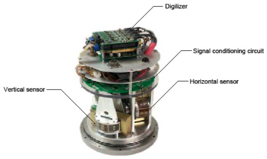
Figure 1.
An assembled 3-axis electrochemical accelerometer.
The sensing element, which is immersed in electrolyte containing an admixture of concentration 0.01 mol/L is essential for adequate performance of the EAM (Figure 2).
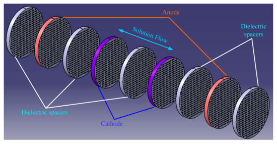
Figure 2.
Decomposed structure of the sensing element.
The rectangular porous electrode (Pt) and dielectric space are designed to contain many channels. This design enables the solution to flow through the electrodes, which in turn allows the current to change when electric potential is applied to the anodes and cathodes. As the EAM sensor is accelerated by external motion, the inner liquid motion and reverse chemical reaction , occur at the anodes and cathodes in each channel, respectively. The interaction of the chemical reaction and fluid motion in the form of the proportional ion concentration gradient generated by acceleration causes the current between the anodes and cathodes to change. The differential current from the two cathodes, which is the output of the sensing element, also forms the input to the signal conditioning circuit for the next process [6,7,8,9,10,11,12,13,14,15].
3. Modeling and Demonstration of the Simulation
3.1. Mathematical Model
According to the operating principles expounded above, the diffusion, convection, and migration processes of the active ions can be expressed by the Nernst–Plank equations as follows:
where is the flux of the active ions, including , , and . , , and are the diffusion coefficients of , , and ; , , and represent the active ion concentrations of , , and , and denotes the electric potential. Further, m is the mobility of the active ions, which is evaluated with the Nernst–Einstein relation:
where D is the diffusion coefficient, is the gas constant, and T is the absolute temperature. According to Faraday’s Law, the output current on the cathode of the sensitive element can be expressed by the flux of the active ions on the surface of the electrode:
where n is the number of electrons exchanged in the electrode reaction; is the Faraday constant; A is equal to the area of the cathode surface that contacts the electrolyte and undergoes the electrochemical reaction.
The fluid velocity field is solved by employing the continuity equation and Navier–Stokes equation:
where is time, denotes the electrolyte density, is the dynamic viscosity, and is the acceleration. According to the principle of electrode dynamics, the dynamic process of the electrode can be completely described by the Butler–Volmer equation [8]:
where is the amount of electricity per mole of electrons in the electrochemical reaction equation, and and are the anodic and cathodic reaction constants, respectively. Further, is the charge transfer coefficient for the cathodic reaction and is set to 0.5 in this study, is the imposed electric potential at the electrodes, and is the equilibrium potential.
In this study, the temperature was set to 300 K. The concentrations of the initial effective electrolytic ions were set to and . The electrolyte density was set to , and the dynamic viscosity of the electrolyte was set to , respectively. We also set , , and . The imposed electric potential is 0.8 V at the anodes and 0 V at the cathodes. The equilibrium potential was set to 0.54 V [1].
3.2. Demonstration of the Proposed Simulation Model
The finite-element multiphysics software Comsol was employed for the numerical simulations to solve a series of physical magnitudes with the input excitation of acceleration in a time-dependent mode (Figure 3). The electrolyte in EAM was an iodine–potassium-iodide solution in which the reaction was essentially the mutual conversion of iodide and iodine ions, i.e., . Potassium ions do not participate in the reaction; thus, the zero-flow boundary conditions should be used for the potassium ions on the electrodes. To simplify the convergence of the simulation results, no slip boundary conditions were applied to the solid surfaces. Electrical insulation conditions were applied to the electric field on the surface of the insulating layer and zero-ion flow boundary conditions were applied to the ion transport. The influence of the electric field was ignored on the left and right exits, after taking into account the distance from the electrode. With the change of external acceleration excitation, an inconsistent pressure distribution is generated due to the microfluidic motion inside the channel, which will change the rate of the electrochemical reaction on the surface of the cathode and anode (Figure 4). By differentially outputting the currents of the two pairs of cathodes, an output current signal generated by the electrochemical vibration sensor at this moment can be obtained.
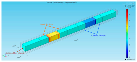
Figure 3.
3D numerical simulation of the sensitive chip channel.
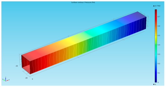
Figure 4.
Pressure distribution at 5 s under .
The current densities on the anode and cathode were acquired by probes and solved under a sinusoidal encouragement of 1 Hz (Figure 5). The graph contains a small linear component, although it has no effect on subsequent analysis. Compared with the situation in [2], the results of the numerical simulation in this paper were validated, and the feasibility of the concept of proposed simulation was demonstrated.
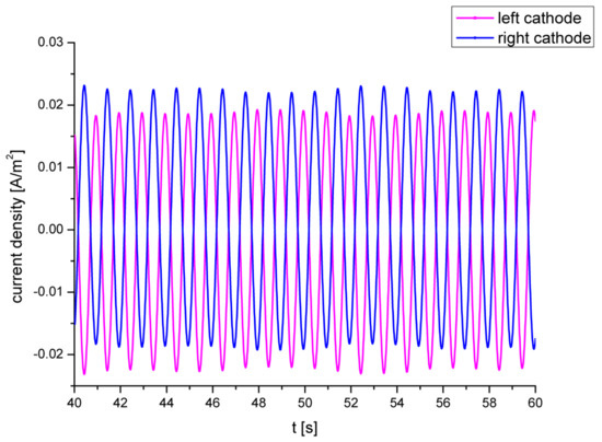
Figure 5.
Current densities at the cathodes under .
4. Establishment and Verification of the Circuit Model
4.1. Proposed AC Equivalent Circuit Model
The model designed to simulate the sensitive chips allows different variables in the model to be adjusted (such as the widths of the cathode and anode, aperture of the single channel of the sensitive chip, and width of the insulating layer between the cathode and the anode). For the single-channel simulation model of sensitive chip, certain variables in the model such as the single-channel aperture are insensitive to frequency variation of the external vibration excitation signal. When these variables change in the model, the output signal of the model does not change significantly for external vibration excitation signals at different frequencies. For the single-channel simulation model of the sensitive chip, the frequency variation of the external vibration excitation signal depends on certain variables of the model (such as the length of the channel, density of the electrolyte, and effective cross-sectional area of the electrode between the channels). A change in these variables in the model causes a significant change in the impedance of the external vibration excitation signal. As the frequency of the external vibration excitation signal increases gradually, the impedance value of the model to the output signal will decrease accordingly, thereby causing the output signal to change in amplitude and phase. The effect of this change is similar to the effect of a capacitor on an output signal in a circuit. Compared to the aforementioned capacitive effect, for the single-channel simulation model of the sensitive chip, there are certain variables of the model (distance between the cathode and anode, diffusion coefficient, etc.) for which the frequency variations of the external vibration excitation signals are similar. However, contrary to the capacitive effect, as the frequency of the external vibration excitation signal is gradually increased, the impedance of the output signal of the system is increased, resulting in an output similar to the circuit in amplitude and phase. The microfluid in the through-hole of the entire channel will have an impedance effect on the external excitation signal, and the impedance generated is mainly from the hindrance of the inertia of the fluid in the single channel to the external excitation signal. Since this parameter is not sensitive to the frequency of the external excitation signal, the impedance is mainly reflected in the equivalent circuit in the form of a resistance. Now, regarding the effect of the medium inductance on the output signal, by continuously changing the experimental conditions corresponding to the influence of variables in the comparison model on the signal input and output, the equivalent model of the single-channel circuit of the electrochemical sensor can be constructed, as shown in Figure 6.
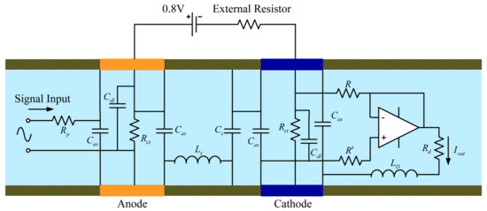
Figure 6.
AC equivalent circuit model for the EAM.
We continued adjusting the parameters corresponding to the influence of various conditions in the model to compare the signal input and output and eventually derived the AC equivalent circuit model for the EAM shown in Figure 6. In this model, the analog acceleration signal, which was the input to the circuit, was abstracted as a small AC voltage signal.
In Figure 6, is the resistance of the through-pores line percolating between the two surfaces, and is the pure dielectric capacitive effect of the electron-ion exchange process in the electrochemical reaction between the insulating layers. Furthermore, denotes the interfacial capacitance between the dielectric spacers and electrodes, is the double-layer capacitance, and , describe the charge transfer resistance and frequent resistance for the liquid flow, respectively. The chief purpose of the amplifier in the equivalent circuit model is to divide the circuit system into a secondary structure. In this manner, the equivalent circuit model of the microfluidic portion of the single-channel sensitive chip can be represented by the first stage of the left end of the operational amplifier. Through the cascade of operational amplifiers, the electrochemical part of the electrode at the right end could be abstracted by an equivalent circuit. The resistance is specified to set the amplification equal to 1. In addition, , denote the resistance effect of the inter-electrode distance and diffusion frequency, respectively. Finally, is the output of the circuit system.
The theoretical impedance of the circuit model for the mechanical and electrochemical systems can be calculated as:
Therefore, the transfer function and phase of the circuit model for the aforementioned two-stage equivalent circuit in the frequency domain can be obtained as follows:
According to Equation (8) and Equation (9) [5], the transfer function is described as
where is the hydrodynamic resistance which is solely determined by the channel geometry under laminar flow conditions, is the density of the electrolyte, is the cross-sectional area of the channel, and represents the length of the channel, which is filled with electrolyte. Further, is the conversion factor of the electrochemical cell, is the diffusion frequency, and d is the inter-electrode distance [5]. Thus, with the correctness of the AC equivalent circuit verified, the corresponding relationships of the variables between the electrochemistry and the electronics are also established.
4.2. Verification of Proposed AC Equivalent Circuit Model
Figure 7 shows the results of the simulations and the power spectral analysis. Figure 7a shows that without the compensation and feedback, a transition time of approximately 8 s is required to initially stabilize the system and an additional 1 s is necessary to respond to the transformation of the input excitation. Since the EAM mainly detects Rayleigh waves, we validated the model with a sinusoidal signal.
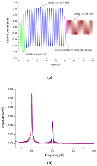
Figure 7.
(a) Current density of the cathodes under from 0 s to 50 s and under from 50 s to 70 s; (b) power spectral analysis of the data in (a).
In the numerical simulation, the different frequencies were scanned while the amplitude was maintained constant; hence, the same method was employed to detect the amplitude of a single channel of the EAM. The output current of the numerical simulation (Figure 8) was used to validate the accuracy of the equivalent circuit.
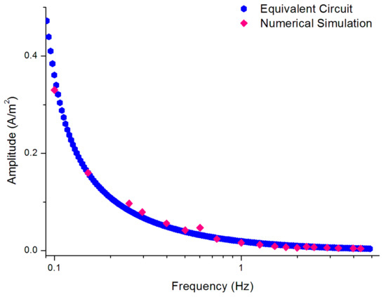
Figure 8.
Amplitude-frequency characteristic of the proposed AC equivalent circuit and the result of simulation of a single channel.
5. Conclusions
Based on the commonly used two-dimensional steady-state model, this paper presents an advanced simulated technology to build a 3D numerical model of an electrochemical accelerometer in the low-frequency range for electronic applications. The 3D time-dependent numerical simulation, which was based on finite element analysis, was designed for the purpose of combining a complex chemical reaction with electric circuit theory. At the same time, as an interesting research for future investigation, we further abstracted the complicated electrochemical and microfluidic processes and proposed an AC equivalent circuit with dynamic characteristics as a foundation for the design of external conditioning circuit. And both the 3D numerical simulation for the EAM and the AC equivalent circuit model in the low-frequency range were validated. According to the AC equivalent circuit model proposed in this study, the impedance matching of the external conditioning circuit of the reaction chamber can be easily performed and mass production of electrochemical vibration sensors can be possible. Through this model, the pure output signal corresponding to the reaction cavity can be obtained for any external excitation signal. Compared to the EAM output signal under the same excitation, we can completely decouple the signal and noise, which will provide favorable conditions for the analysis of static natural convection noise and dynamic noise of EAM in the future, so that EAM can better suppress noise effectively in the preparation process.
Author Contributions
Conceptualization, Q.Z.; methodology, Y.C.; software, B.L.; validation, Q.Z.; formal analysis, Y.C.; writing-original draft preparation, Y.C.; writing-review and editing, Y.C. and J.H.; project administration, Q.Z.
Funding
This research received no external funding.
Conflicts of Interest
The authors declare no conflict of interest.
References
- Sun, Z.; Agafonov, V.M. Computational study of the pressure-driven flow in a four-electrode rectangular micro-electrochemical accelerometer with an infinite aspect ratio. Electrochim. Acta 2010, 55, 2036–2043. [Google Scholar] [CrossRef]
- Li, G.B.; Chen, D.Y.; He, W.T.; Wang, J.B. Micro-machined electrochemical seismic sensors with interdigital electrodes. In Proceedings of the 13th Annual Conference of Chinese Society Micro-Nano Technology, CSMNT 2011, Changchow, China, 28–30 September 2011; pp. 61–66. [Google Scholar]
- Sun, Z.; Agafonov, V.M. 3D numerical simulation of the pressure-driven flow in a four-electrode rectangular micro-electrochemical accelerometer. Sens. Actuators B Chem. 2010, 146, 231–238. [Google Scholar] [CrossRef]
- He, W.T.; Chen, D.Y.; Li, G.B.; Wang, J.B. Low frequency electrochemical accelerometer with low noise based on MEMS. In Proceedings of the 13th Annual Conference of Chinese Society of Micro-Nano Technology, CSMNT 2011, Changchow, China, 28–30 September 2011; pp. 75–80. [Google Scholar]
- Huang, H.; Yu, H.; Agafonov, V. Molecular electric transducers as motion sensors: A review. Sensors 2013, 13, 4581–4597. [Google Scholar] [CrossRef] [PubMed]
- Huang, H.; Carande, B.; Tang, R.; Oiler, J.; Zaitsev, D.; Agafonov, V.; Yu, H. A micro seismometer based on molecular electronic transducer technology for planetary exploration. Appl. Phys. Lett. 2013, 102, 193512. [Google Scholar] [CrossRef]
- Huang, H.; Carande, B.; Tang, R.; Oiler, J.; Zaitsev, D.; Agafonov, V.; Yu, H. Development of a micro seismometer based on molecular electronic transducer technology for planetary exploration. In Proceedings of the IEEE 26th Internatoinal Conference of Micro Electro Mechanical Systems, MEMS, Taipei, Taiwan, 20–24 January 2013; pp. 629–632. [Google Scholar]
- Newson, J.; Riddiford, A. The kinetics of the iodine redox process at platinum electrodes. J. Electrochem. Soc. 1961, 108, 699–706. [Google Scholar] [CrossRef]
- Kozlov, V.A.; Terent’ev, D.A. Frequency characteristics of a spatially-confined electrochemical cell under conditions of convective diffusion. Russ. J. Electrochem. 2002, 38, 992–999. [Google Scholar] [CrossRef]
- Zhou, Q.; Li, D.; Wang, Y. Self-noise analysis of four-electrode microflow-electrochemical accelerometer inspired by hemodynamic model. Appl. Mech. Mater. 2014, 461, 984–992. [Google Scholar] [CrossRef]
- Kozlov, V.A.; Terent’ev, D.A. Transfer function of a diffusion transducer at frequencies exceeding the thermodynamic frequency. Russ. J. Electrochem. 2003, 39, 401–406. [Google Scholar] [CrossRef]
- Agafonovz, V.A.; Nesterov, A.S. Convective current in a four-electrode electrochemical cell at various boundary conditions at anodes. Russ. J. Electrochem. 2005, 41, 880–884. [Google Scholar] [CrossRef]
- Zhou, Q.; Wang, C.; Chen, Z.; Chen, S.; Lin, J. Dynamic response analysis of microflow electrochemical sensors with two types of elastic membrane. Sensors 2016, 16, 657. [Google Scholar] [CrossRef] [PubMed]
- Li, G.; Sun, Z.; Wang, J.; Chen, D.; Chen, L.; Xu, C.; Qi, W.; Zheng, Y. A flexible sensing unit manufacturing method of electrochemical seismic sensor. Sensors 2018, 18, 1165. [Google Scholar] [CrossRef] [PubMed]
- Agafonov, V.; Egorov, E. Electrochemical accelerometer with DC response, experimental and theoretical study. J. Electroanal. Chem. 2016, 761, 8–13. [Google Scholar] [CrossRef]
© 2019 by the authors. Licensee MDPI, Basel, Switzerland. This article is an open access article distributed under the terms and conditions of the Creative Commons Attribution (CC BY) license (http://creativecommons.org/licenses/by/4.0/).