1. Introduction
The eco-friendly vehicle market is expanding, and various electric vehicle models and associated technologies are being developed. Moreover, strict regulations are imposed on the average CO
2 emissions and the particulate matter generation from internal combustion engine vehicles, such as gasoline- and diesel-fueled cars. As a result, electric vehicles are gaining acceptance in most countries, such as in Europe and the United States of America. Furthermore, limited vehicle types, such as passenger cars, are being converted into electric vehicles; moreover, various small electric vehicles, including smart mobility vehicles, are under development [
1].
The driving motors in electric vehicles have a considerable influence on the driving performance, and are available in various configurations [
2,
3,
4,
5]. However, recently, the price of the rare earth magnets used in brushless DC motors (BLDCs) has rapidly increased, thus causing a rise in product prices, and therefore, decreasing their product price competitiveness. As a result, most of these vehicle manufacturers’ profits are now being spent on material imports, causing a direct reduction in the profitability of their companies. Therefore, there is a growing technical need to replace BLDCs, and hence, developmental research on simply structured induction motors that are cheaper than BLDCs is indispensable [
6,
7,
8].
Various approaches have been employed to improve the efficiency of induction motors; moreover, research and development is still ongoing. Typical methods include modeling using the finite element method [
9,
10], optimization using artificial neural networks (ANNs) coupled with the genetic algorithms (GAs) [
11,
12], development of the associated motor materials [
13], and improvisation through magnetization of the barriers and slits [
14].
Previously, Kumar et al. proposed a new approach to minimizing copper and iron losses and optimizing the efficiency of variable speed induction motor drives [
15]. Their method was based on a simple induction motor field-oriented control model. However, they only used the conventional induction motor parameters, and as a result, some iron loss occurred. Additionally, Sakthivel and Subramanian proposed a new approach that utilizes particle swarm optimization (PSO) to evaluate the field efficiency of the induction motors by employing a model based on the modified induction motor equivalent circuits [
16]. Similarly, Delgado et al. presented an optimization plan called “edge optimization,” which is a simple recognition algorithm for induction motors, and has no derivative model. Their proposed approach relies on the hardware or software startup information of the motor for identification of all seven induction motor parameters, namely, the stator leakage inductance, rotor leakage inductance, stator resistance, rotor resistance, mutual inductance, mechanical inertia, and the friction coefficient [
17].
Considering the parameters affecting the performance of induction motors, Faiz et al., using analytical statistics, demonstrated the negative impact of the power-supply unbalanced voltage on the efficiency of the induction motors, as well as the associated financial losses [
18]. Similarly, Donolo et al. investigated the effects of voltage imbalance on the performance of induction motors. Using a sequence equivalent circuit, they determined the increase in losses of the induction motors and analyzed motors with open and closed rotor slots [
19]. Jabr and Kar proposed experimental procedures for determining the mechanical parameters and the saturation characteristics [
20], by employing an experimental procedure that facilitates easy measurement of the reactivity saturation characteristics of both the stator and the rotor. In addition, Rasouli et al. investigated possible induction motor parameter identification, with particular emphasis on the subset selection and reduction methods, such that the identification method could focus on the most important parameters [
21]. Finally, Kostov et al. proposed an efficient approach to determine the equivalent circuit parameters of squirrel-cage induction motors based on genetic algorithms [
22]. Moreover, when three data sets were used in their study, the maximum relative error of the estimated parameters with respect to the analysis values was found to be less than 1%.
In this study, shape optimization design for a low-cost, high-efficiency, outer rotor induction motor is performed based on electromagnetic field analysis and experimental observations. Therefore, an induction motor design with high efficiency, and hence, a high-power output in various speed ranges is proposed. This is achieved by targeting a low-speed and high-torque-section setup, to ensure that the motor provides high efficiency and high-power output at various driving speeds other than the rated speed. Note that an outer rotor induction motor is selected over an inner rotor induction motor, as the former has strong rotational inertia, a small rate of change of speed, and stronger structural characteristics compared to the latter. As the rated output and rated speed of the induction motor are determined in proportion to the frequency and number of poles, the basic design specifications are selected via a parameter-based formula.
The remainder of this paper is organized as follows.
Section 2 presents the motor shape design and behavioral trends based on the induction motor design procedure. Through the understanding of the characteristics of outer rotor induction motors, the basic specifications are tuned by changing the number of poles. In
Section 3, the feasibility of the basic design of the outer rotor induction motor is discussed using an electromagnetic field analysis assessment.
Section 4 and
Section 5 report the production of prototypes of the optimally designed outer rotor induction motor and their overall characteristics. The design error is determined and minimized by comparing the electromagnetic field analysis values and the measured values. Finally, the conclusion is presented in
Section 6.
2. Outer Rotor Induction Motor
An induction motor is a representative example of alternate current (AC) motors. Owing to the rotating magnetic field generated by the stator, an induction current is generated in the rotor of the electric conductors and a rotational torque corresponding to the slip is generated. Induction motors are divided into single-phase induction motors and three-phase induction motors, according to the type of AC power input; three-phase current is generally used, which can obtain a rotating magnetic field without any special techniques. As it does not step out like a synchronous motor, which is also an AC motor, it is considered suitable for loads with large torque fluctuations. However, it has difficultly in controlling the rotational speed, owing to the principle of obtaining torque through slip. Nevertheless, because the rotational speed can be freely controlled by the inverter circuit, thanks to the development of power electronics, this problem can be considered nearly solved.
One advantage of the outer rotor induction motor is that the generated torque increases with an increase in the cross-sectional area of the permanent magnet, and its structure is advantageous for prevention of scattering of the magnet. However, it is difficult to rotate at high speeds due to problems with mechanical stability and the possibility of demagnetization. Nevertheless, the outer rotor induction motor has numerous advantages in mechanical performance. First, to accommodate the stator, the outer rotor is larger than the rotor of the inner rotor induction motor. Owing to an increased rotor size, the inertia increases, thereby reducing the torque ripple and the cogging torque and providing smooth and stable operation, even at lower speeds. Second, it normally generates a higher torque compared to similar sized inner rotor induction motors. The torque is a magnetic force multiplied by the air gap radius (magnitude of magnetic flux), which is related to the output of the induction motor. For the same induction motor diameter, the outer rotor induction motor has a larger air gap area than that of the inner rotor induction motor, and larger air gaps can produce higher power. Third, a larger radius of the air gap also results in an increased "lever arm" for torque generation. In an outer rotor induction motor, the larger the diameter of the rotor, the higher the number of poles the rotor can accommodate, which further increases the magnetic flux.
The outer rotor induction motors have shorter accumulation compared to the inner rotor induction motors with similar performance characteristics. Their smaller size and a higher torque production facilitate their application as in-wheel induction motors in electric vehicles and propellers in remote-controlled model drones. In the case of high-precision applications, such as optical drives, their smooth and consistent speeds have an advantage over other induction motor types. Moreover, in various load applications, such as industrial power tools, pumps, fans, and blowers, the high inertia of outer rotor induction motors can reduce the load changes and provide a stable output torque. Due to the specific design advantages of outer rotor induction motors, they are commonly applied in fans and blowers. The outer rotor can serve as a hub for the fan or blower impeller. It provides a compact case and acts as a heat sink for the impeller to rotate, which facilitates induction motor cooling.
3. Outer Rotor Induction Motor Design Outer Rotor Induction Motor
To design the outer rotor induction motor for application in electric vehicles, the basic design specifications were determined considering the driving characteristics of electric vehicles. Then, the equivalent circuit method and the finite element method were primarily applied to the design process. The typical characteristics of the outer rotor induction motor were identified. After identifying the performance problems through prototype production, the design was optimized to make it more similar to the prototype by adjusting the number of poles.
3.1. Basic Design Specification Selection
An electric vehicle motor has a limited battery capacity; therefore, the input voltage was limited to 48 V. For low-speed operation, the rated speed was limited to 1000 rpm or less. The design targets were a 1.2-kW rated output, 80% efficiency, 12 Nm torque, and an output density of 0.5 kW/kg or more.
3.2. Electrical Steel Selection
There are two types of electrical steel sheets: Oriented and non-grain oriented sheets. The former is an electrical steel sheet in which the crystal magnetization is aligned in the rolling direction and is mainly used in transformers or reactors. A non-grain oriented electrical steel sheet exhibits uniform magnetic properties in the rolling and other directions, and is mainly used as a material for electric motor cores. Non-grain oriented electrical steel sheets are further divided into two types, depending on their thickness: 0.5 and 0.35 mm. There are 10 types of 0.5 mm sheets, which range from 50PN370 to 50PN1650 depending on the silicon content. There are five types of 0.35 mm sheets, ranging from 35PN320 to 35PN560, depending on the silicon content. As the first two digits of the label represent the iron plate thickness and the last three digits represent the iron loss value, it is advantageous to use a thinner steel plate to reduce the Eddy current losses, and to select a material with a lower iron loss.
The electrical steel used in this study was S08 0.35T, 35PN230 according to the POSCO standards. This was a non-grain oriented electrical steel sheet with a density of 7.6 kg/dm3, a maximum iron loss of 2.3 W/kg, a minimum magnetic flux density of 1.62 T, and a space factor exceeding 95%.
3.3. Number of Poles and Slot Combination
The number of slots in the squirrel-cage rotor must be carefully determined considering the number of stator slots. In addition to the noise generated during operation or starting, the starting torque causes a significant change in the rotor position, and the primary cause of abnormal torque is the mismatch between the stator and rotor slot combinations.
For three poles, the number of grooves in the stator is preferably a multiple of three. A multiple of 6, 12 or 18 may be selected for 2, 4 or 6 poles, respectively, as detailed in
Table 1. It is common for the number of rotor slots to exceed the number of stator slots. Furthermore, designing a difference of more than 20% between the number of stator and rotor slots can reduce the motor noise and the leakage reactance. Moreover, the higher the number of grooves, the better the output, maximum torque, efficiency, and the power factor. However, this setup also reduces the coil space factor; therefore, appropriate values must be selected.
For this study, the number of poles for the design was selected as 6, which could yield the same torque at lower frequency compared to 8 poles, as detailed in
Table 2. For high output and high efficiency, the number of stator and rotor slots was 72 and 88, respectively.
3.4. Motor Dimensions
In order to design an outer rotor motor in this study, it was necessary to determine the outer diameter of the rotor. First, we considered mounting of the motor on an electric bike, with its volume being equivalent to
, which is proportional to the motor output and torque and which determines the motor thermal stability. The detailed dimensions of the stator and the rotor of motor were determined through application of the design procedure. The relevant formulae and associated values in millimeters (mm) are presented in
Table 3.
4. Analysis of Induction Motor Characteristics via Electromagnetic Field Analysis
4.1. Slot Combination
The stator and rotor slot combination to yield the optimal conditions with regards to the output, efficiency, torque, and the weight was derived according to the pole number fluctuations with 16 poles, as demonstrated in
Figure 1. With a higher number of slots, the output and the torque were found to improve, as shown in
Table 4. Moreover, higher efficiencies were obtained in a certain range. Considering the overall characteristics of the motor, the optimal characteristics could be obtained with a combination of 90 stator slots and 124 rotor slots, as indicated by the blue box in
Figure 1.
Table 4 lists the motor characteristic data values along with the torque values.
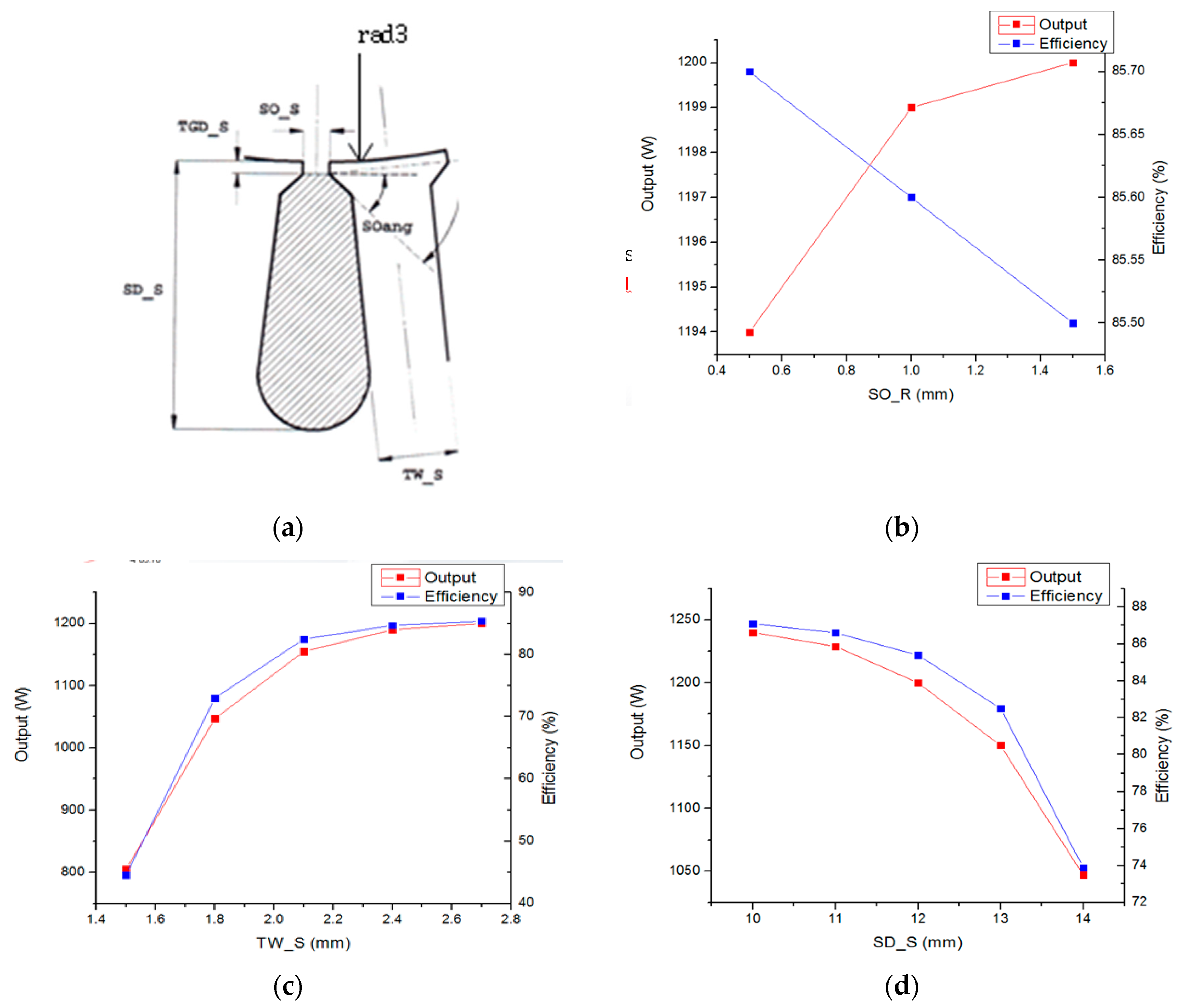
4.2. Stator Slot Shape
Figure 2a depicts a stator slot opening. With an increase in the stator slot opening, the output increases, and the efficiency decreases, as shown in
Figure 2b. In
Figure 2a, SOAng is the stator slot opening angle, and SO-S is the slot opening. TW_S is the width of the stator rotor, and SD_S is the slot depth of the stator. Note that the coil thickness for winding should be considered, i.e., only the slot opening with dimensions larger than the winding thickness should be selected.
Furthermore, as the stator tooth thickness increases, as shown in
Figure 2c, the output and efficiency increase, as well because it is in proportion to the thickness. However, such an increase in tooth thickness renders the motor predominantly iron-based, which increases its weight.
Finally, as the stator slot height increases, the overall output and efficiency decrease (
Figure 2d). However, for this study, it was necessary to increase the winding area to accommodate as many windings as possible. Therefore, it was essential to secure a certain slot area, even if it decreased the output and efficiency slightly.
4.3. Rotor Bar Shape
Considering the rotor shape design (
Figure 3a), with increases in the bar thickness and the depth, as shown in
Figure 3b,c, respectively, the motor output and efficiency increases as well. In
Figure 3a, SetBack is the depth of the rotor slot opening, and SD-R is the slot depth of the rotor. Furthermore, SO-R is the width of the rotor slot opening. Accordingly, the slot area becomes wider, which yields increased power output due to the increased amount of aluminum.
An increase in the rotor slot opening corresponds to an increased power output (
Figure 3d); however, the efficiency is inversely related. Therefore, the slot opening of the bar should be set to the optimal point in terms of output and efficiency.
4.4. Lamination
As shown in
Figure 4, increasing the lamination increases the efficiency, and above a certain level of lamination, it reduces the power output of the induction motor. After the efficiency exceeds a certain level, the graph exhibits a saturation-like behavior, showing a very slight change. In this study, considering the output density, an optimum level of 30 mm was selected, which yields the highest efficiency compared to weight.
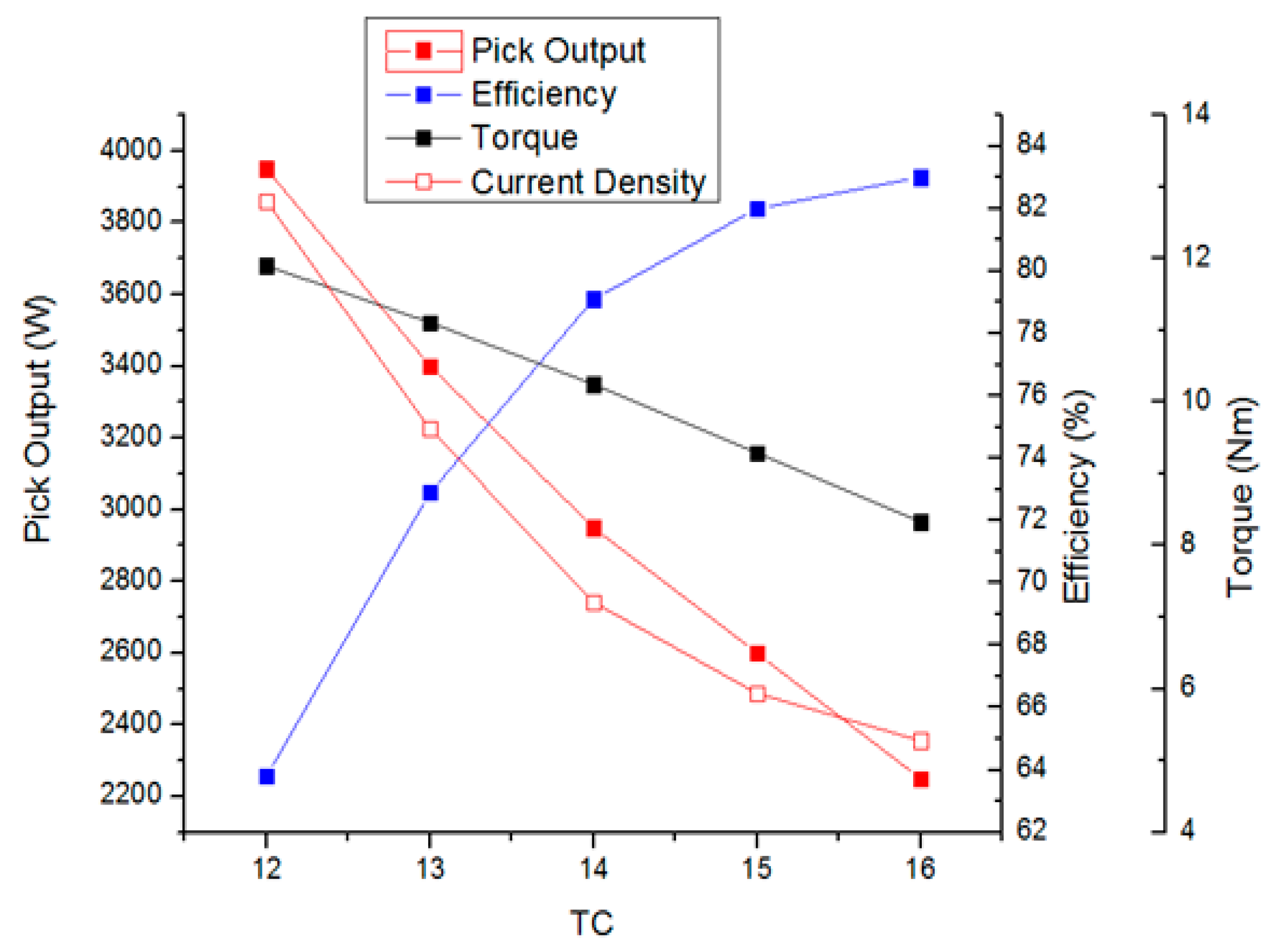
4.5. Wire Diameter and Turn Count
For winding optimization, it is necessary to determine the wire diameter and turn count by considering the stator’s space factor. In this study, the optimal point was derived by fixing this space factor to be less than 45%, and through adjustment of the wire diameter and the turn count. Examination of the turn count trend revealed that the output, efficiency, torque, and the current density tend to decrease as the turn count increases, as shown in
Figure 5. The point at which the desired output relative to the efficiency was obtained was considered the optimal point. The characteristics according to the turn count are listed in
Table 5.
4.6. End Ring Design
Due to the use of distributed windings, the coil end rings had a greater height than that obtained for concentrated windings. Therefore, when the rotor was die-cast, it was necessary to produce a rotor end ring of similar height to increase the output and efficiency.
Figure 6 depicts the structure of such a rotor end ring. Generally speaking, however, if the end ring height increases continuously, this may result in an increase in the overall motor weight, thus yielding a reduced output density. In this study, the windings were set as fixed components and the motor characteristics were observed with the variation in height of the rotor end ring. When this height exceeded a certain level, the efficiency curve became saturated (
Figure 7). The point with the best motor characteristics relative to the weight was identified as the optimal point.
Table 6 shows the motor characteristics according to the motor end ring structure. The output efficiency weight was analyzed when the end ring of the motor was increased from 10 mm to 15 mm. The motor end ring is 80.8% efficient at 10 mm thick and 81.3% at max. 15 mm.
4.7. Summary of Trend Analysis
As the design optimization progressed, the influence of each item on the motor characteristics was determined and the motor was reconstructed.
Table 7 summarizes these trends and elucidates the characteristics of the outer rotor induction motor. The rated output, efficiency, and weight, are directly related to the output density, which are indicated by arrows. The factors with considerable changes are indicated by red arrows.
5. Fabrication of Outer Rotor Induction Motor Prototype and Performance Evaluation Device
Based on the design data, an induction motor prototype was fabricated to allow comparison of the electromagnetic field analysis results with actual experimental data. The device used for evaluating the performance of the fabricated inductor (speed, torque, efficiency, etc.) is also discussed in this section.
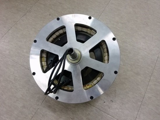
5.1. Fabrication of Outer Rotor Inductor
Figure 8 shows three-dimensional (3D) modeling images and photographs of the actual outer rotor inductor and the assembled outer rotor inductor. In detail,
Figure 8a,b shows a 3D drawing of the inductor stator and rotor, respectively, while
Figure 8c shows the winding method for the inductor stator.
Figure 8d shows the actual stator fabricated based on the drawing, which was manufactured using a 35PN230 non-grain oriented electrical steel sheet with 90 slots.
Figure 8e shows the inductor rotor core, which was manufactured using the same material as the stator.
Figure 8f shows the coil winding of the stator. The turn count was 15 and the wire diameter was 0.45 mm. The winding was produced with four reels and 6 poles in parallel. Finally,
Figure 8g shows the assembled fabricated outer rotor inductor.
5.2. Outer Rotor Inductor Performance Evaluation Device
Figure 9a shows the inductor test equipment. The test equipment employed in this part of the study was a dynamo system produced by Dr. Staiger Mohilo & Co. GmbH (Lorch, Germany). The dynamo system was equipped with a servo motor to simulate load conditions, a torque sensor to measure the motor torque, and a power analyzer that could assess a variety of electrical conditions. Therefore, this device could measure the overall performance of the motor.
Figure 9b shows the motor configuration installed into the test equipment. Measurements were performed under test conditions of 25 °C and 50% humidity. A certain frequency was applied according to the number of poles. To perform measurements in the 1000 rpm section, which was the rated speed section, the efficiency, power, torque, and power factor were measured by adjusting the load from 0 to 800 rpm.
6. Inductor Performance Evaluation
In accordance with the design procedure for the outer rotor induction motor, the overall shape design and operating trends were first identified using the electromagnetic field analysis design tool described above. An actual motor having the shape-optimized model was then fabricated and tested.
A six-pole model was selected as the initial model for production and performance evaluation. Comparison of the electromagnetic field analysis and actual measurement results revealed that the efficiency of the latter was at least 30% lower. To improve the efficiency, the frequency was increased in order to accelerate the induction motor. Thus, the design was optimized by varying the frequency by increasing the number of poles; as a result, the difference between the electromagnetic field analysis and measurement results was found to be reduced.
6.1. 6-Pole Model Performance Evaluation
The motor constructed using the shape-optimized model was utilized and the motor efficiency, torque, and output were tested by varying the voltage with respect to the frequency. To obtain the rated speed of 1000 rpm with 6 poles, a frequency of 55 Hz was required, and the efficiency was measured to be 53% under those conditions. Experiments performed with varying frequencies and voltage values revealed that a higher frequency corresponds to higher efficiency, but lower output and torque. In addition, the driving voltage was adjusted based on 48 V, and was found to be proportional to the output and torque, but inversely proportional to the efficiency, which is contrary to the results obtained for frequency. These results are presented in
Figure 10 and
Table 8.
6.2. 10-pole Model Performance Evaluation
For the 6-pole design and measurement, improved efficiency with increased frequency was confirmed. While maintaining the rated speed, consistent at 1000 rpm, the pole number of the fabricated motor was changed to 10. The subsequent experiment was conducted in the same manner as the experiment with 6 poles. Based on the rated speed, 90 Hz frequency was applied for 10 poles. The efficiency was found to be increased compared to the 6-pole model, with a confirmed maximum of 77%. This result validates the approach of changing the number of poles to improve the efficiency. The detailed results are shown in
Figure 11 and
Table 9.
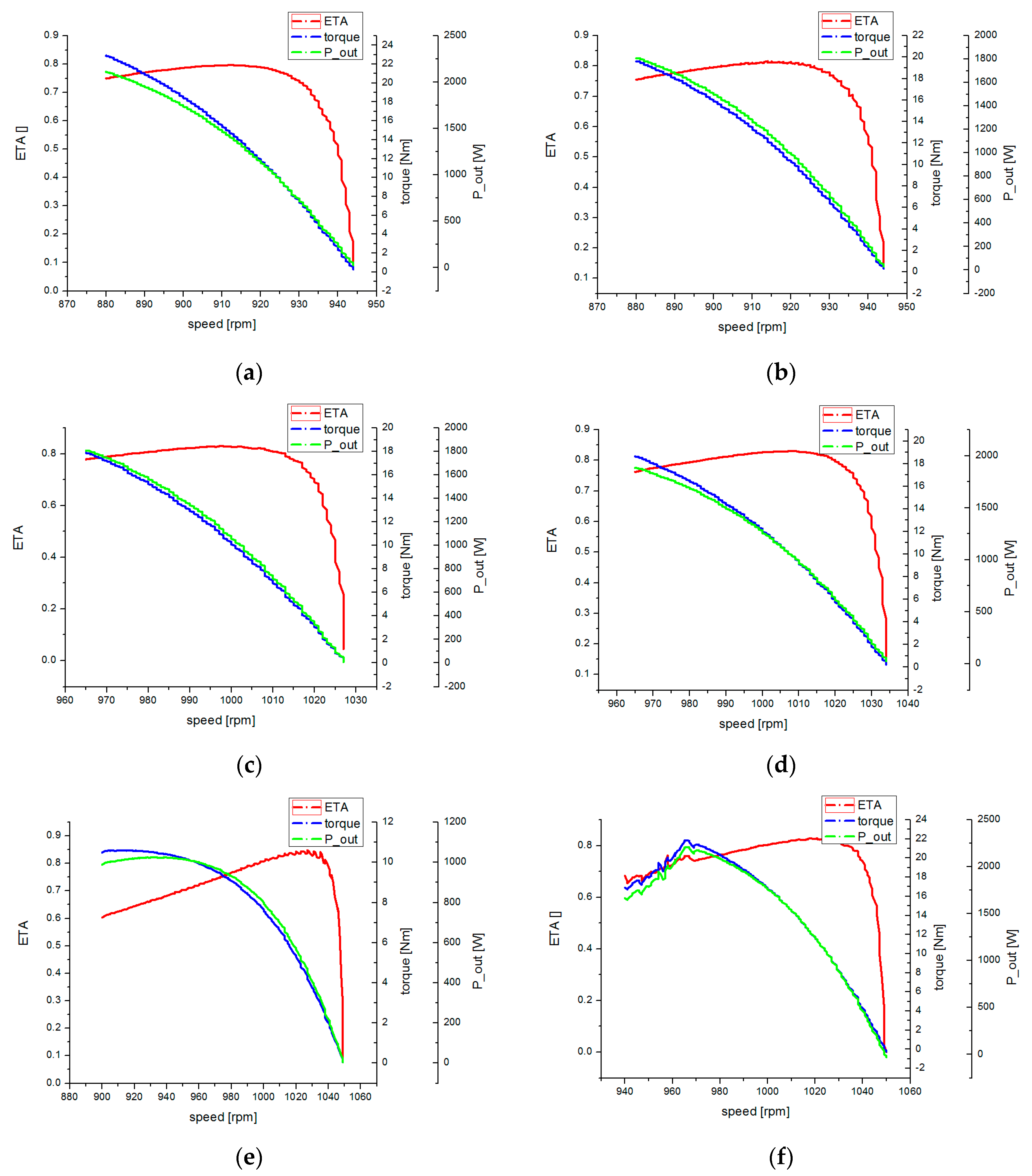
6.3. 16-pole Model Performance Evaluation
To improve the efficiency of the induction motor, the number of poles of the motor was increased to 16 poles during fabrication. In terms of the experimental method, this study evaluated the performance of the outer rotor inductor in the same manner as the 10-pole model.
Figure 12 shows graphs of the motor characteristics of the inductor according to the number of poles and voltage frequencies; the experimental results for each frequency are shown. The experiment was conducted within a frequency range of 126–140 Hz, and a maximum efficiency of 84.8% was experimentally confirmed. With 16 poles, the frequency for the rated speed was 140 Hz, and in terms of the measured values, at 33.2 V, the efficiency was 82.7%, the output was 1.2 kW, and torque was 11.4 Nm. As such, the design through the electromagnetic field analysis and the results of the actual manufactured outer rotor inductor were found to be consistent. In the case of a lesser number of poles of the induction motor, the coil end extended, causing extensive copper loss, and therefore, degrading the efficiency. Through this experiment, this study verified the method of improving the efficiency of a large induction motor by increasing the number of poles. The detailed results are presented in
Table 10.
7. Conclusions
In this paper, the basic theory and design procedure of an outer rotor induction motor were described; moreover, a drive motor shape was designed using the equivalent circuit method and the finite element method. Based on the basic shape design, an optimized design was developed by adjusting the number of poles.
For effective application of an induction motor to an electric vehicle, a design yielding improved efficiency and power density, which are the most critical factors, is required. In this study, the design variables that affect the efficiency and power density of an outer rotor induction motor were classified. Furthermore, by analyzing the trends appearing through variable adjustments, the effects of each variable on the efficiency and output were determined.
An outer rotor induction motor has a large outer diameter and short axial length. Further, additional poles are known to be required, compared to those of a typical inner rotor induction motor. This is because the coil pitch is increased according to the employed distributed winding method. Moreover, the amount of available windings was reduced, owing to the larger outer diameter; as a result, there was a longer coil pitch and a reduced number of available windings. This aspect may have yielded the measurement results obtained in this study for the outer rotor induction motor with 6 poles. Superior results were obtained when the motor was fabricated with a higher number of poles. This is because the narrower pole spacing reduced the coil pitch, significantly increasing the usable range of the coil compared to the six-pole model; hence, the efficiency measured in the actual performance evaluation matched the analytical efficiency value. Use of a pancake-shaped winding in the motor, with a large outer diameter and a short axial length, appeared to be effective. This approach was also found to be more advantageous in terms of output density, because the maximum output can be increased with application of the driving voltage when the motor characteristics were obtained at a voltage lower than the driving voltage.
Thus, to achieve the maximum performance of an electric vehicle with an outer rotor induction motor, characteristics such as high torque of the motor parts in the low-speed range, high efficiency in the operating range, and a relatively small battery to allow low-voltage operation and to reduce the overall weight are required. To realize these characteristics, a pancake-shaped outer rotor induction motor, which is different than that of an inner rotor induction motor, was designed in this study. Furthermore, the important design variables were derived through shape optimization design and production of many prototypes. The motor was then optimized to meet the performance indicated by the electromagnetic field analysis. The performance evaluation device confirmed that the test results were similar to the designed results, and the validity of the design was verified. In the future, this outer rotor induction motor design is expected to be widely applied to electric vehicles and bicycles.


