Article

A Novel Active Cell Balancing Circuit and Charging Strategy in Lithium Battery Pack

1
Department of Electrical Engineering, National Taitung Junior College, 911, Jhengci North Road, Taitung 95045, Taiwan
2
Department of Electrical Engineering, National Chin-Yi University of Technology, 57, Section 2, Chungshan Road, Taiping District, Taichung 41107, Taiwan
*
Author to whom correspondence should be addressed.
Energies 2019, 12(23), 4473; https://doi.org/10.3390/en12234473
Submission received: 18 October 2019 / Revised: 11 November 2019 / Accepted: 20 November 2019 / Published: 24 November 2019
(This article belongs to the Section D: Energy Storage and Application)

Abstract

:
A novel, active cell balancing circuit and charging strategy in lithium battery pack is proposed in this paper. The active cell balancing circuit mainly consists of a battery voltage measurement circuit and switch control circuit. First, all individual cell voltages are measured by an MSP430 microcontroller equipped with an isolation circuit and a filter circuit. Then, the maximum cell voltage difference is calculated by subtracting the minimum cell voltage from the maximum cell voltage. When the maximum cell voltage difference exceeds 0.05 V, the balancing action starts to carry on. The MSP430 microcontroller output controls signals to close the switches corresponding to the battery cell with the maximum voltage. At this time, the balancing charge power performs a balancing charge for other batteries, except for the one that is switched on. In addition, a three-stage balancing charge strategy is also proposed in this paper to achieve the goal of speedy charging with balancing action. In the first stage, a 0.5 C balancing current is used to perform pre-balanced charging on all battery cells until the maximum cell voltage difference is less than 0.05 V, which is required for entry to the second stage of charging. In the second stage, constant current charging of 1 C, coupled with 0.2 C balancing current charging is carried out, until the maximum battery cell voltage reaches 4.2 V, which is required for entry into the third stage of charging. In the third stage, a constant voltage charging is coupled with 0.2 C balancing current charging, until the maximum battery cell voltage reaches 4.25 V, which is required to complete the balancing charge. The imbalance of power between the battery cells during battery pack charging, which reduces battery charging efficiency and battery life, is thus effectively improved. In this paper, a six-cells-in-series and two-in parallel lithium battery pack is used to perform a balancing charge test. Test results show that the battery cells in the battery pack are capable of quickly completing a balancing charge under different initial voltages, the maximum voltage difference is reduced to within the range of 0.05 V, and the total time required for each balancing charge is approximately 3600 s.

1. Introduction

The extensive use of fossil energy by humans has a great impact on the environment. Not only do the traditional steam locomotives consume a lot of oil resources but the exhaust gas emitted is also one of the main causes of the greenhouse effect. Therefore, finding a way to save energy and reduce carbon has been the topic of discussion in various countries [1,2]. In response to the environmental protection policies in different countries, electric vehicles powered by electricity have flourished. Secondary batteries are the key energy storage components for electric vehicles. Secondary batteries have wide applications. With the wide applications of secondary batteries and the advancement of electronic technology, the performance of batteries has also attracted a lot of attention. Currently, the most common secondary battery is a lithium battery, because of its high working voltage, high energy density, absence of memory effect, low self-discharge rate, long life, etc. [3,4]. In order to meet the high power demand, lithium batteries usually increase the battery pack voltage and capacity through series–parallel connection. However, due to the varied battery charging and discharging characteristics and aging, power imbalance between batteries might result, thereby, reducing battery charging and discharging efficiency and seriously affecting battery life. Hence, battery balance is indispensable [5,6,7,8,9,10,11,12,13,14,15,16]. Many research literature have proposed a variety of balancing charging techniques, such as the resistive balancing method, the capacitive balancing method, the inductive balancing method, the transformer balancing method, and the power converter balancing method. However, the resistive balancing method uses one resistor at both ends of the battery for circuit balance purpose. When the charger is charging and the battery voltage reaches a certain value, the switch is turned on, which discharges excessive energy through a resistor to balance the battery voltage. The capacitive balancing method uses a capacitor to transfer energy. Each capacitor is connected to two batteries through the switch. Through the action of the switch, excessive energy can be converted between the batteries to achieve voltage balance. The inductive balancing method is made up of two switches and one inductor, which are used to transfer energy. Through the switching of the switch, the battery energy with a higher voltage is stored in the inductor, and the energy in the inductor is transferred to another battery with a lower voltage. The transformer balancing method performs energy transfer at the battery pack end through winding to achieve voltage balance. The transformer’s winding can store energy in the battery or battery pack and transfer the energy to the necessary battery [17,18,19,20,21,22,23,24]. The power converter balancing method transfers energy between power and batteries through voltage increases and decreases, combined with the use of the switch [25,26,27,28,29]. The above battery balancing methods come with various disadvantages, such as a complex circuit structure, loss caused by circuit actions, and excessive components [30,31,32,33].
This paper proposes a new lithium battery pack active cell balancing circuit and a three-stage charging strategy. The charging process is divided into three stages. The first stage is the pre-balancing stage, with a balancing current of 0.5 C. The balancing circuit will measure the voltage of each cell and calculate the maximum voltage difference between batteries. When the maximum voltage difference exceeds the set value of 0.05 V, the circuit will commence the balancing action and open the switch corresponding to the battery with maximum voltage. At this time, the balancing charging circuit will commence balancing charging on other batteries until the maximum voltage difference range of the battery is less than 0.05 V. At this point, the circuit balancing is considered to be complete. The second stage is the main charging stage, with a charging current of 1 C. At this time, the balancing current decreases to 0.2 C, and the circuit commences constant current charging on all batteries. At the same time, the voltage differences among all batteries continue to be measured. When the maximum voltage difference exceeds 0.05 V, the circuit performs balancing charging action on the batteries. When the battery with the maximum voltage is charged to 4.2 V, the charging power enters the third stage, the constant voltage charging stage, until the battery with the maximum voltage reaches 4.25 V and the charging shuts down to complete the entire charging process. The charging strategy proposed in this study is different from the traditional CC–CV charging strategy in the main charging stage to the second stage. In this paper, in addition to the main charging current a balance current was also used, which allows reduces the balance charging time [34]. In this study, the six in-series and two in-parallel lithium battery pack was used to carry out the actual balancing charging test. The test results showed that the respective battery cells in the battery pack could reduce the maximum voltage to within the 0.05 V range, under different initial maximum voltage differences, with a balancing charging time of approximately 3600 s.

2. Structure of Active Cell Balancing Circuits

The active cell balancing circuit of the lithium battery pack is shown in Figure 1, which is mainly composed of two parts, namely, the charging circuit and the balancing charging circuit. The circuits include a power supply, a switch circuit, a battery pack, a battery voltage measuring circuit, and a MSP430 microcontroller. The battery voltage measuring circuit consists of an INA128 isolation circuit, a low-pass filter and a reversing amplifier. The measured voltage signal passes through the MSP430 microcontroller to control the switch control circuit.

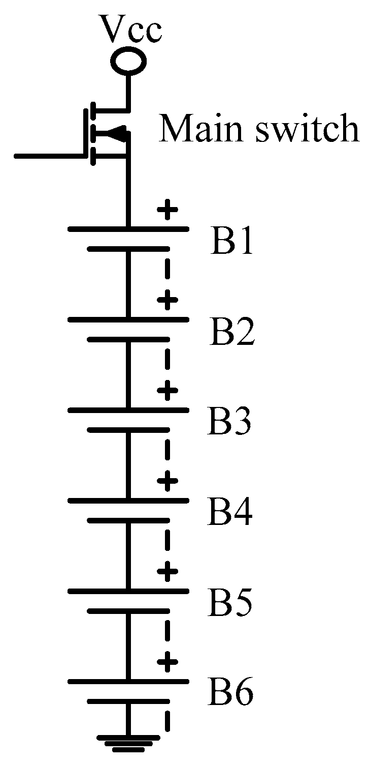
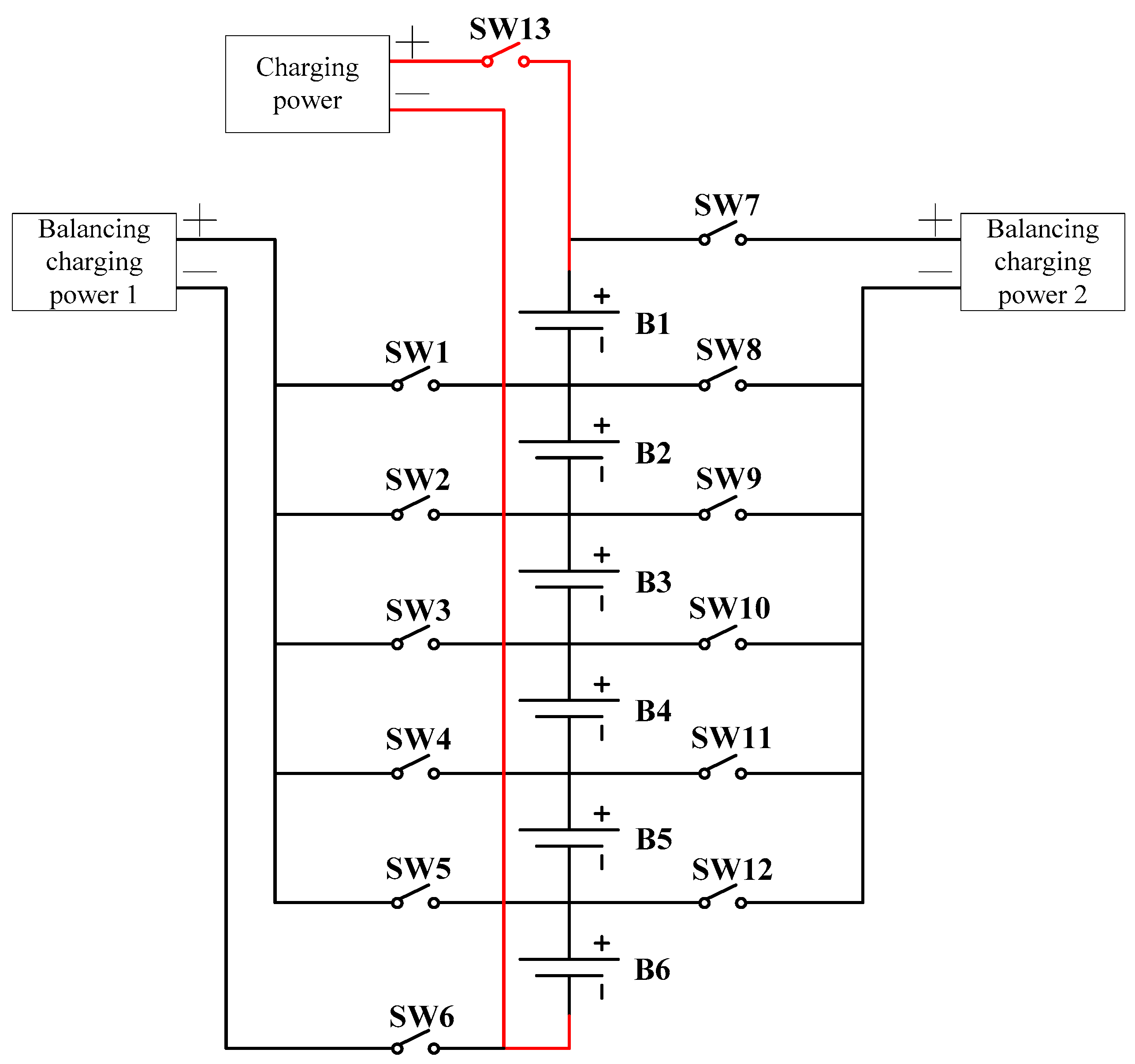
2.1. Charging Circuit of a Lithium-Battery Pack

Figure 2 shows the charging circuit of a lithium-battery pack. The MSP430 microcontroller sends the control signal to the main switch. When the main switch is ON, the power supply provides the charging current to the battery pack for charging. At this time, the battery pack begins charging. When the main switch is OFF, the power supply is turned off and the battery pack charging is completed.

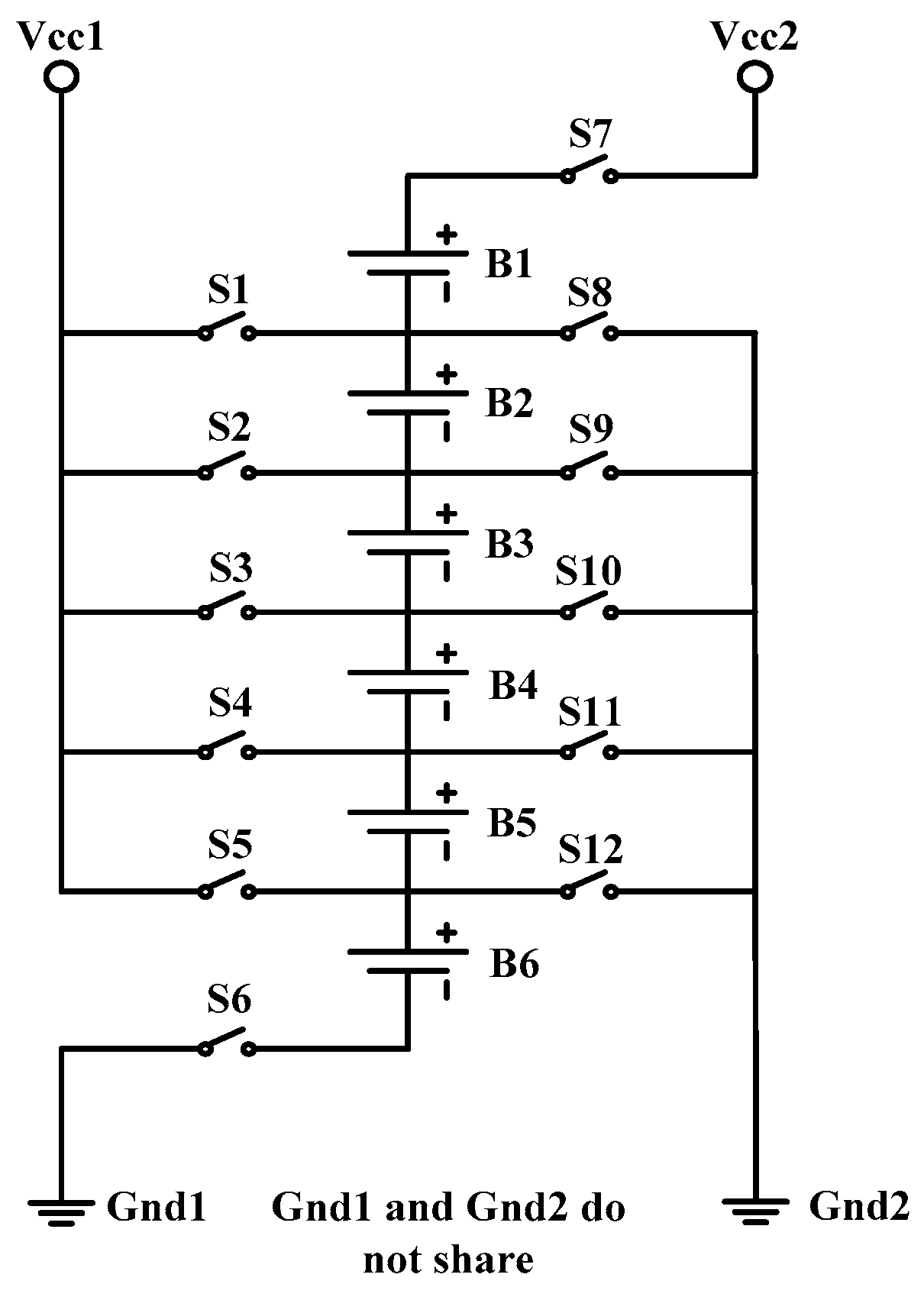
2.2. Balancing the Charging Circuit of a Lithium-Battery Pack

Figure 3 shows the balancing charging circuit of a lithium-battery pack. This circuit carries out the balancing charging on the battery through the MSP430 microcontroller that controls the switch. First, the battery voltage measurement circuit measures the voltage of each battery cell. After computing and determining that balancing is required, the MSP430 microcontroller sends control signals to the corresponding switches and the bypass loop of the corresponding battery is opened. When the switch is ON, both power supplies provide charging current to the corresponding battery to charge. At this time, the battery starts balancing the charge. When the switch is OFF, both power supplies are turned off. At this time, the battery pack balancing is completed.
The battery voltage measurement circuit, switch circuit, and the lithium-battery pack in the lithium-battery pack balancing charge circuit are detailed below.

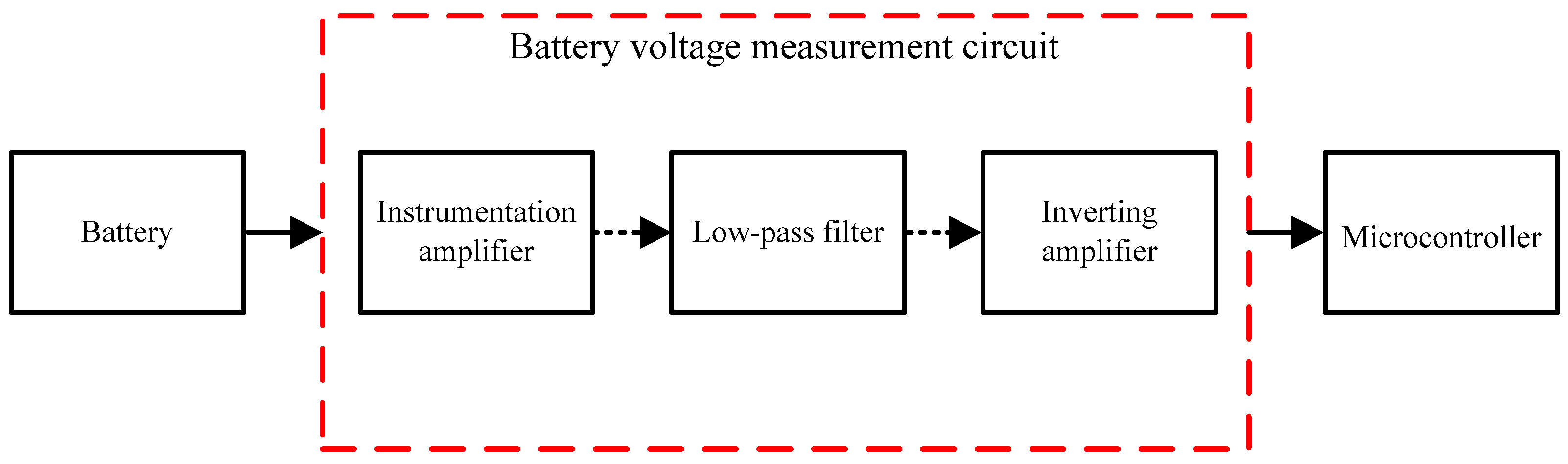
2.2.1. Battery Voltage Measurement Circuit

Figure 4 shows the battery voltage measurement circuit designed in this paper. This circuit consists of three parts—the instrumentation amplifier isolation circuit, the low-pass filter circuit, and the inverting amplifier circuit. Through the instrumentation, the amplifier’s infinite input impedance feature, the output terminal is isolated. In order to prevent the battery from external noise interference during the measurement process and causing the signals to be unstable, the low-pass filter is connected at the back to filter the high-frequency noise. The A/D conversion input of the MSP430 microcontroller used here has a maximum voltage of 3.3 V. Since the battery voltage range is 2 V–4.2 V, the inverting amplifier is needed to attenuate the input signal to the limited input range and to then send it to the A/D converter of the MSP430 microcontroller. Through program computing, balancing the charging control is carried out on the battery. Each parallel battery is complemented by a voltage measurement circuit to carry out the measurement. The battery pack model used in this paper is also conjunctively used. Six voltage measurement circuits are used to perform the measurement and control.

2.2.2. Switch Circuit

Figure 5 shows the switch circuit proposed in this study. A TLP3543 optical coupling relay is used as a balancing switch. This IC is composed of two MOSFETs, and the MOSFET is turned on by an internal light-emitting diode. The six-series and two-parallel battery pack is used in this paper to perform actual the charging and balancing charging tests. A total of 13 switches are used for switching. When the number of parallel batteries increases in the future, the total number of switches of the proposed switch circuit will not increase.

2.2.3. Lithium-Battery Pack

The battery pack used in this study is a lithium battery IBR18650BC manufactured by E-ONE MOLI ENERGY CORP. The specifications are shown in Table 1. The capacity of a single battery is 1500 mAh, the rated voltage is 3.6 V, the maximum charging voltage is 4.2 V, the minimum discharge voltage is 2 V, the maximum charging current is less than 9 A, and the maximum discharge current is 30 A. The battery module in the balanced charging mode proposed in this paper uses 12 IBR18650BC to form six series and two parallel lithium battery modules. Since the batteries in parallel have an equal voltage, only one series of battery cell needs to be measured to represent the voltage of the two parallel batteries.

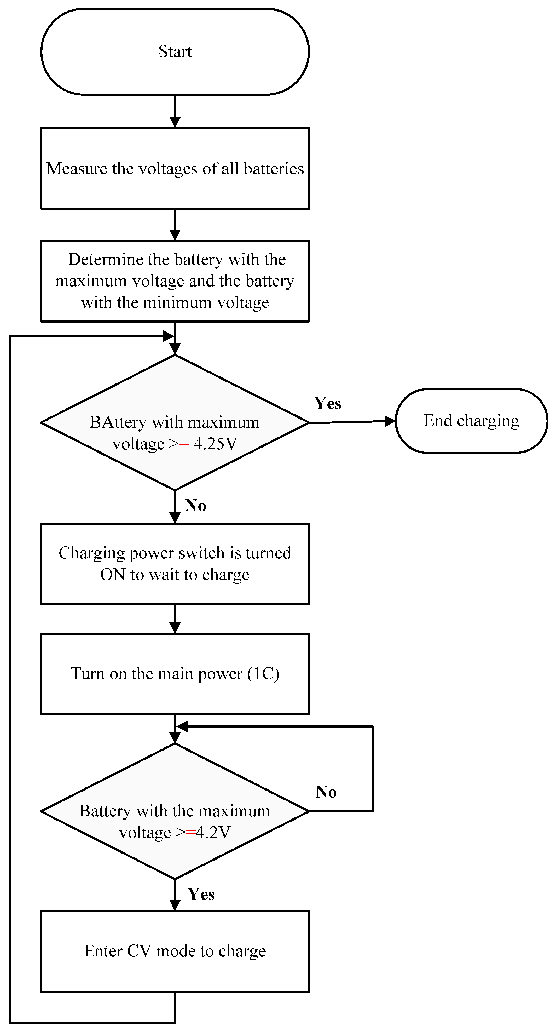
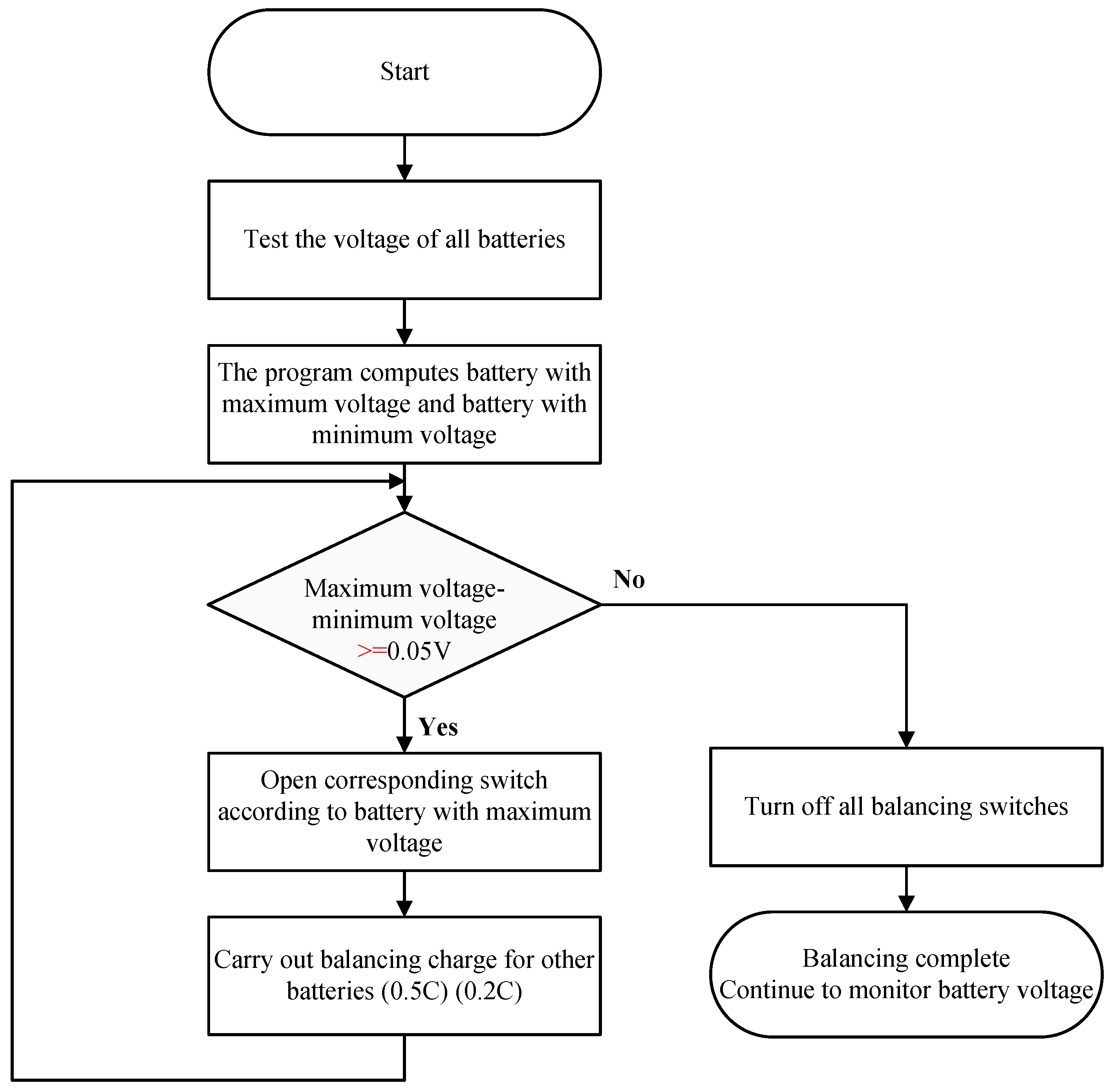
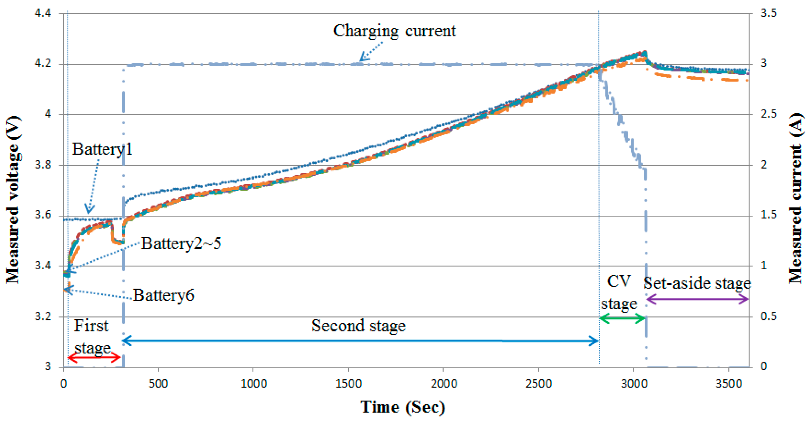
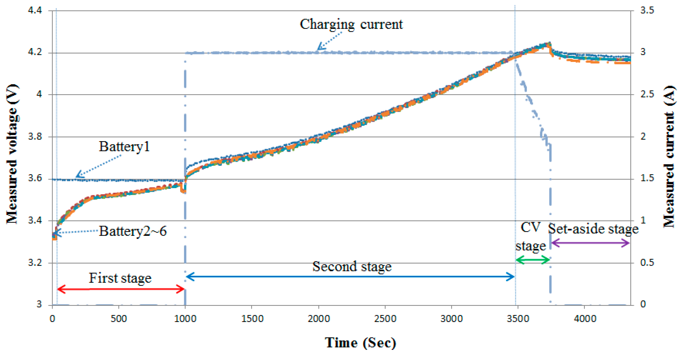
3. The Experimental Processes

This study proposes a new three-stage active cell balancing charge strategy of lithium battery. The charging process is mainly divided into three stages. The overall flowchart is shown in Figure 6.
The balancing charging method in this study involves the usage of 13 switches, including a battery-pack charging and a balancing charging. The switching action states corresponding to the imbalance states are summarized in Table 2. As shown in Table 2, the relationship between each switch action of the seven imbalance states proposed in this paper is mainly related to all switch actions in different states.
Then, the charging method of the battery pack balancing charging structure in this paper involves the use of a constant current (CC) and a constant voltage (CV) charging. This charging method is a two-stage charging. In the first stage, constant current charging is adopted. When the battery voltage is low, a higher current is delivered to charge, in order to reduce the overall charging time. However, when the battery voltage rises to the rated voltage, in order to prevent overcharging and ensure that the current is actually charged into the battery, it is necessary to convert into the second stage of constant voltage charging. At this time, the charging current will gradually decrease with time, until the current approaches zero. Although this method can almost fully charge the battery, the current under CV charging is very small, and the charging time is almost twice or three times that of CC charging, thus, the lengthy overall charging time. Therefore, in order to reduce the overall charging time, this study made slight adjustments to the CC–CV charging method, with the CV transition condition being set in the battery, with the maximum voltage reaching 4.2 V, until the battery with the maximum voltage reaches 4.25 V to turn off the power supply. At this time, charging is said to be completed. Figure 7 shows the overall flowchart of the charging action.
The balancing charging method utilizes CC to charge. This charging method charges batteries through fixed small currents. To adjust the current size, an external charging power (power converter) is needed to control the charging current size. In this study, two constant current power supplies are used to provide the balancing charging power. The switch circuit performs charging on different quantities of batteries, according to different imbalance situations. The voltage at the power terminal provides a fixed current based on the voltage of the battery. Although the balancing circuit cannot enable the battery to reach a stable voltage by constant voltage charging, it can perform rapid balancing on the battery pack when multiple batteries have lower voltages. Figure 8 shows the overall flowchart of the balancing charging action.

4. Testing Results and Discussions

In the balancing charge testing, there were four balancing conditions to be analyzed and discussed, which were the first-stage, pre-balancing current value, second-stage, balancing current value, CC–CV transition condition, and the cut-off of charging. For each condition, three parameters were selected to carry out and compare. At the beginning of the measurement, the charging was turned on after a 30 s interval, and the final maximum voltage difference was observed by standing for 10 min after the completion of charging. The selection of balancing charge conditions for testing are tabled in Table 3.

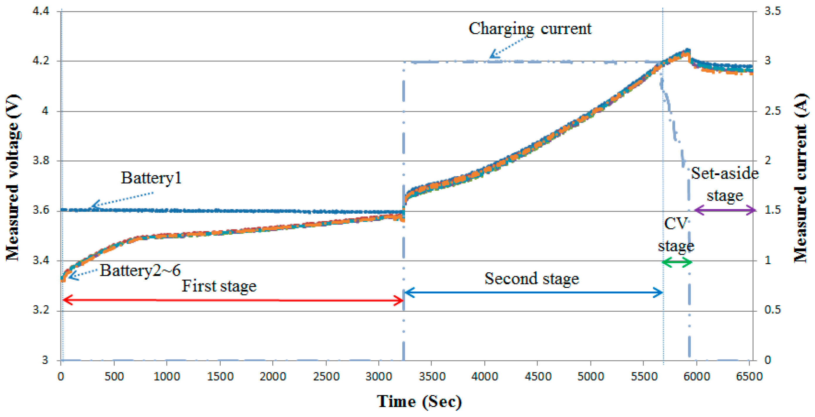
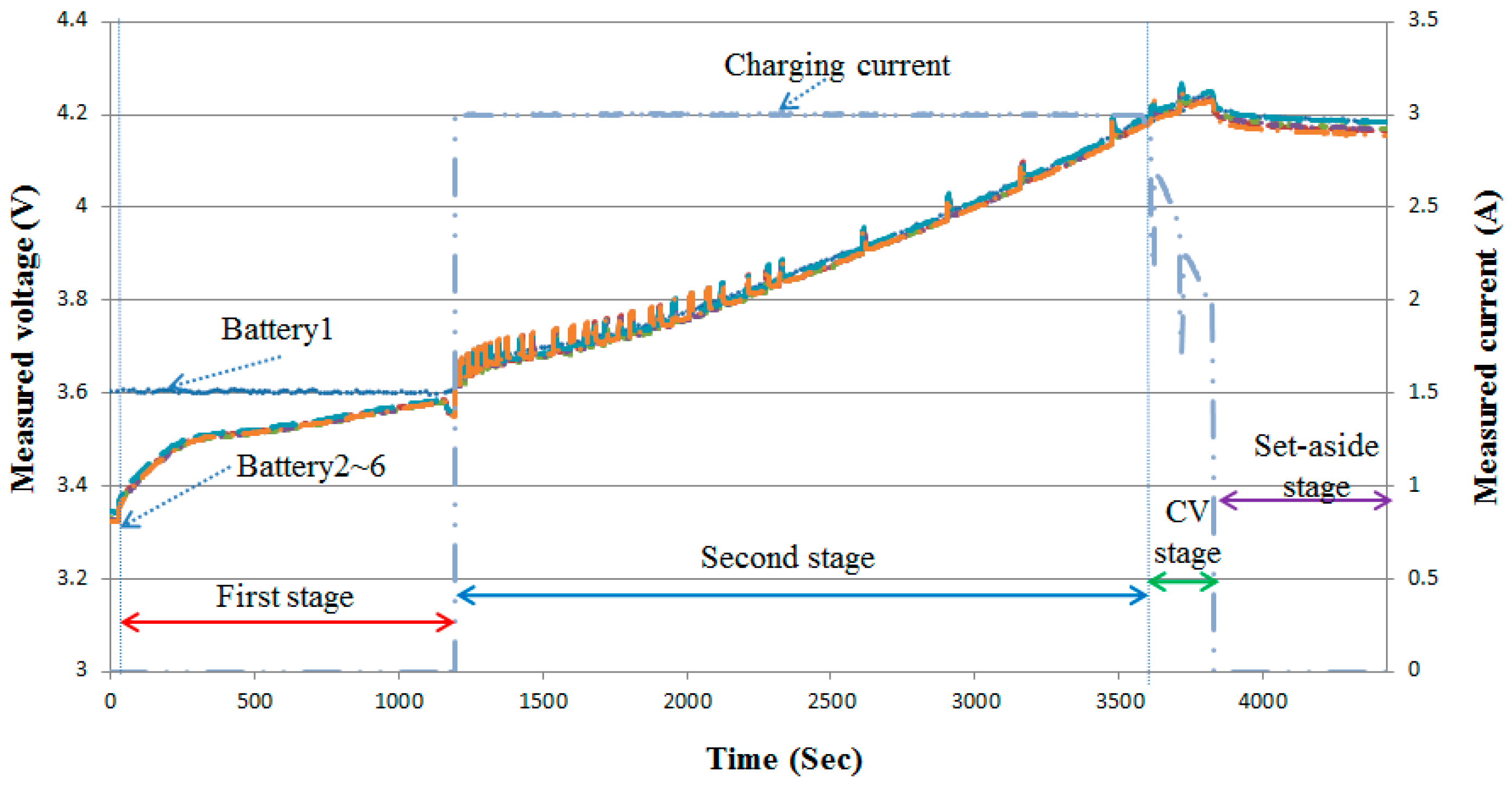
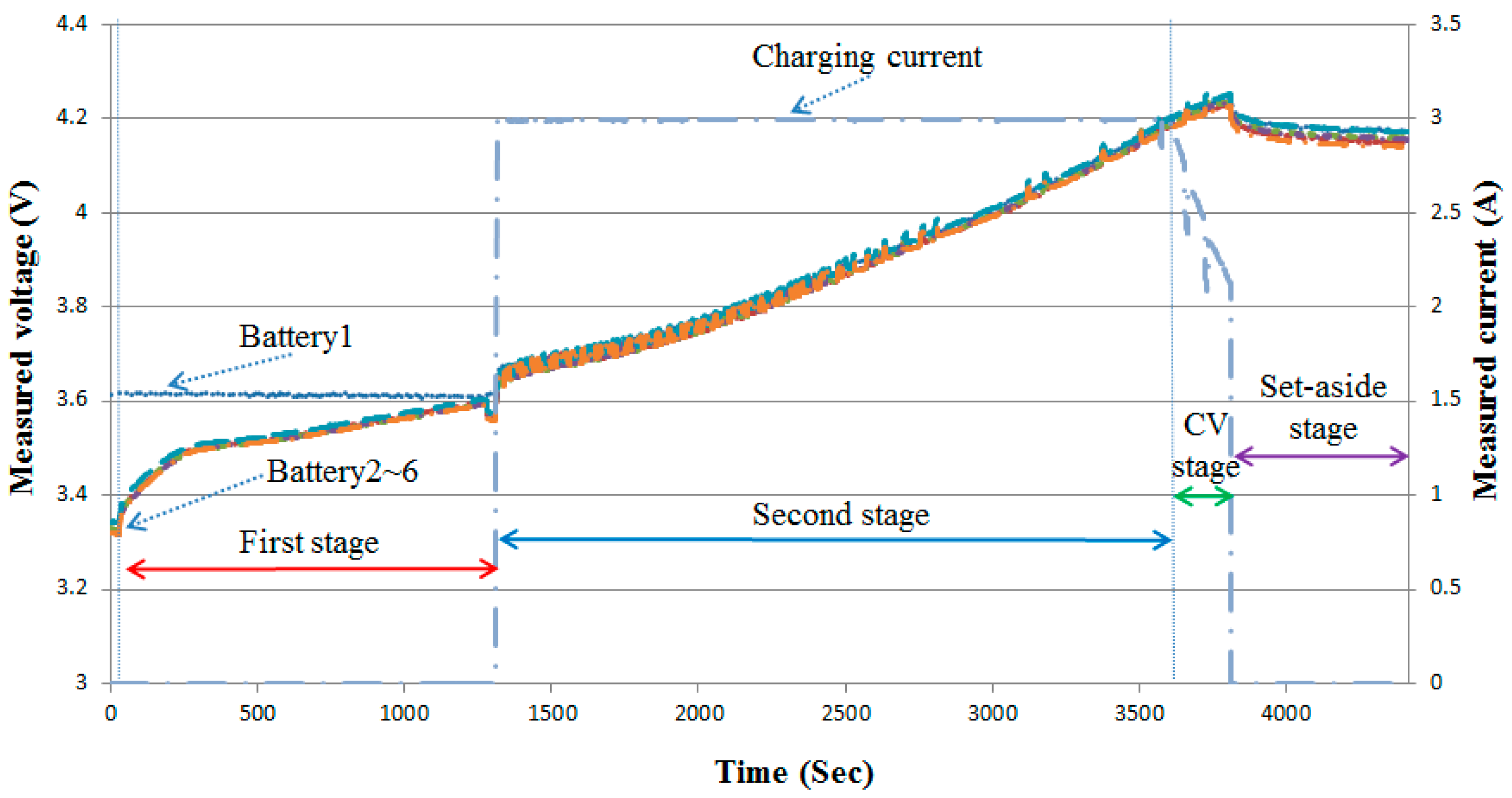
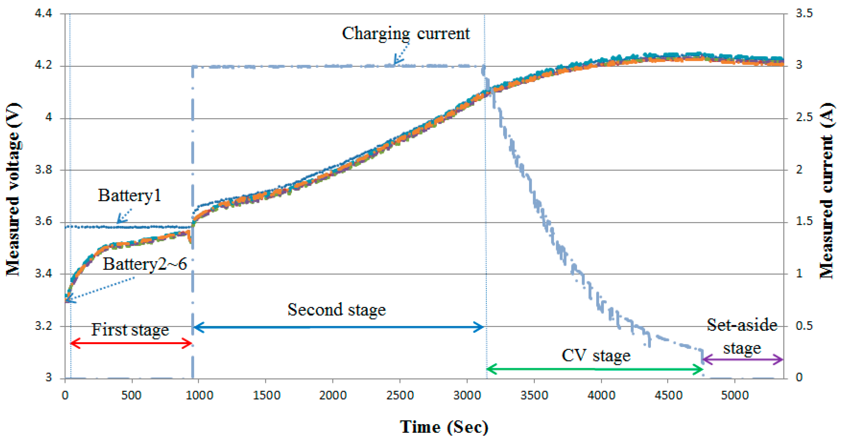
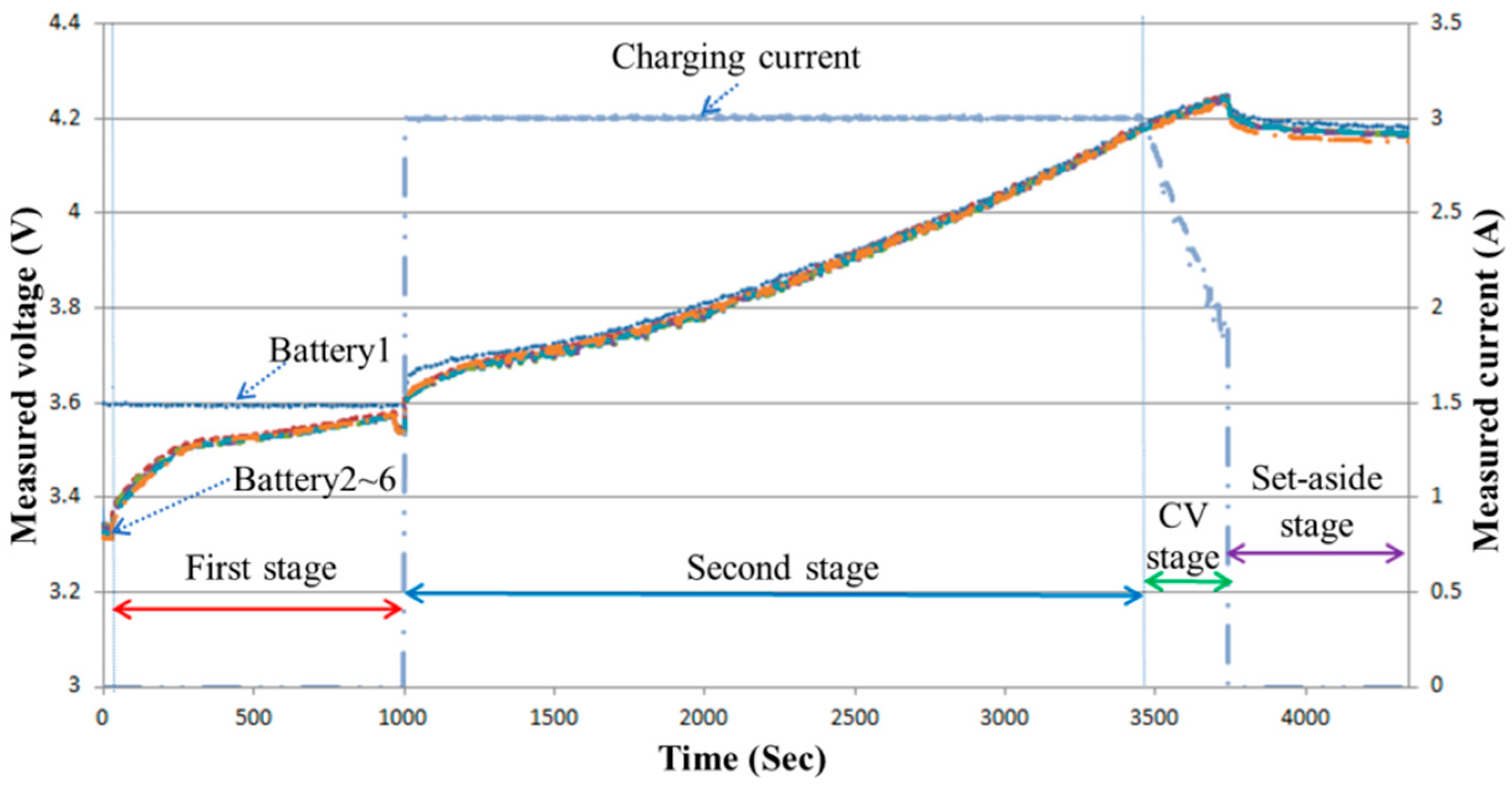
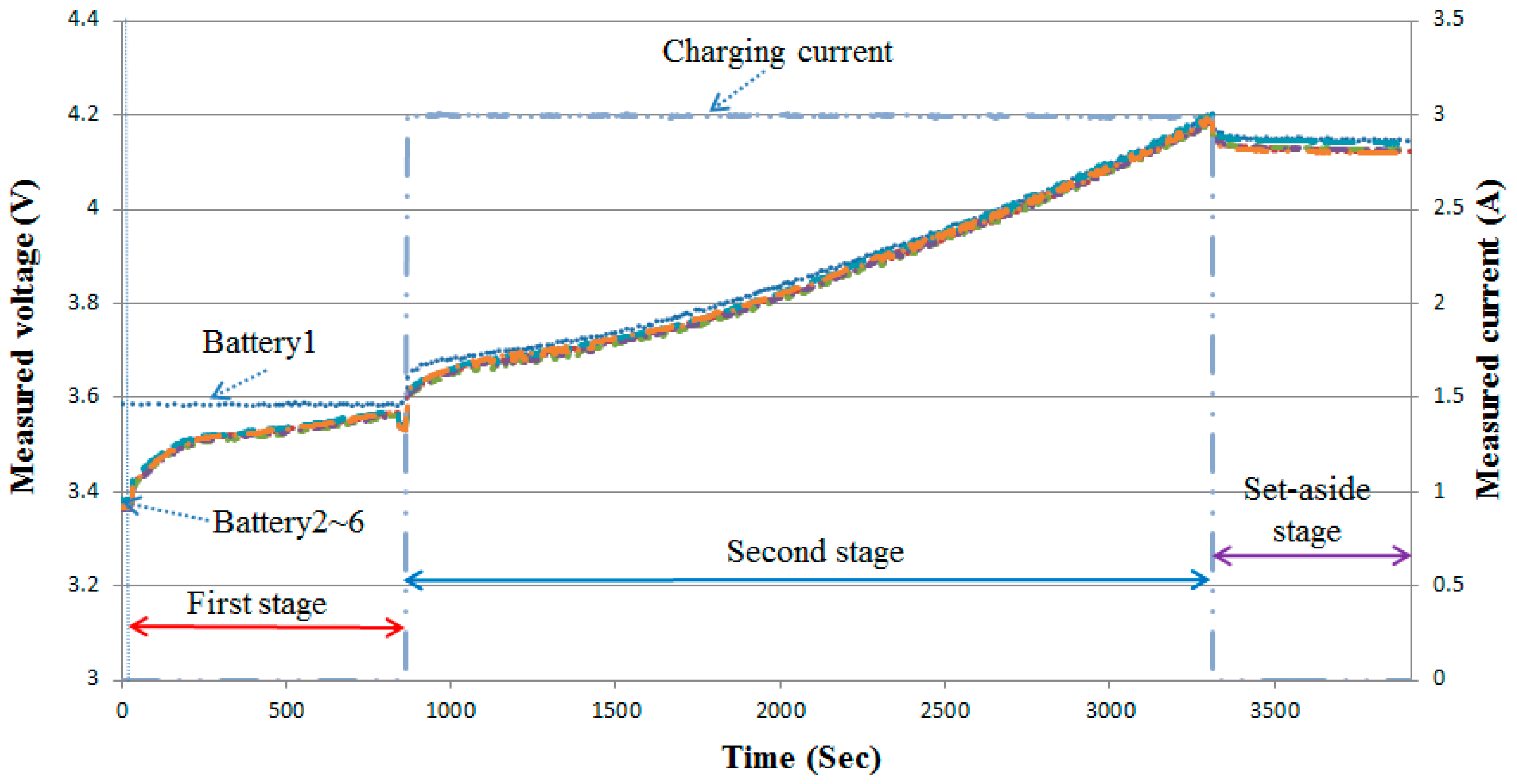
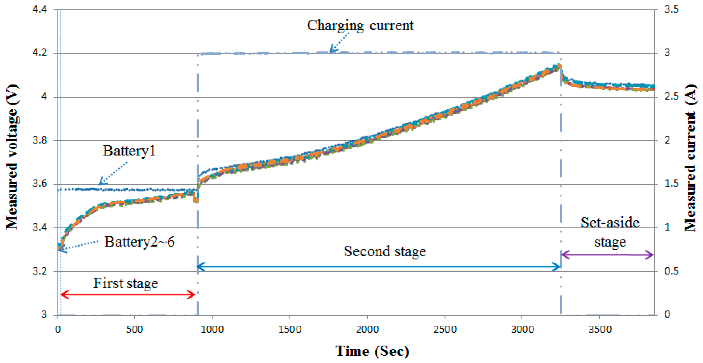
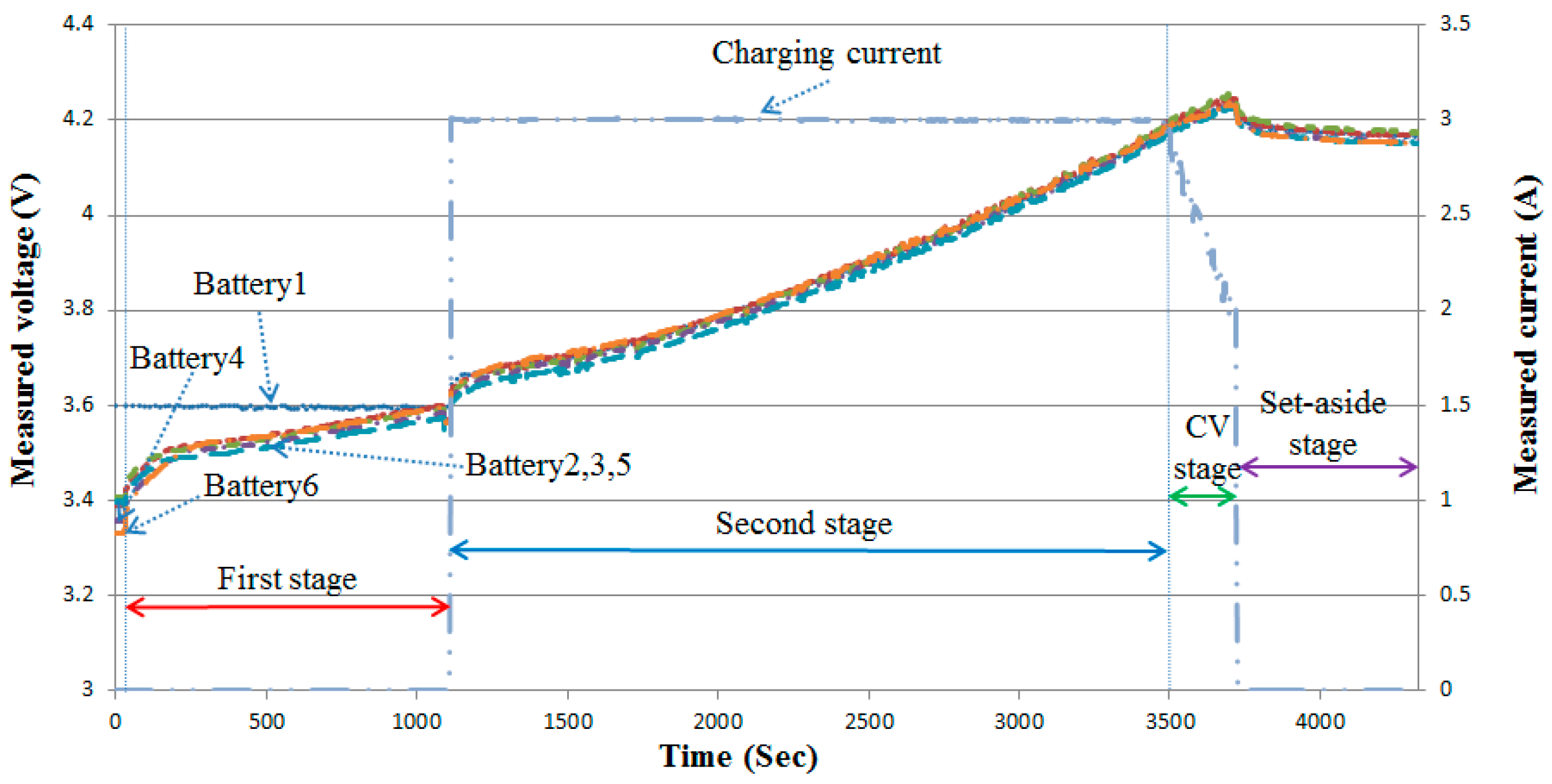
4.1. First-Stage Pre-Balancing Current Value Analysis

Figure 9 shows the actual test results of the first-stage balancing charging using 1 C balancing current. There were four steps in the balanced charging experiment at this stage. Step 1 was pre-balancing, with 1 C charging; Step 2 was balancing, with 0.2 C charging; Step 3 was the CV stage, with the maximum battery voltage reaching 4.2 V transition; Step 4 was the rest stage where the maximum battery voltage reached 4.25; the battery was then turned off and was in the rest stage for 10 min. Under the initial state, the maximum voltage difference was 0.278 V, the total charging time was 3065 s, the final voltage difference after setting aside for 10 min was 0.04 V, and the average voltage was 4.163 V.
Figure 10 and Figure 11 show the actual test of the first-stage balancing charge with 0.5 C and 0.2 C balancing current; under the initial state, the maximum voltage difference, the total charging time, the final voltage difference after setting aside for 10 min, and the average voltage are shown. The balancing charges were 0.284 V, 3743 s, 0.032 V, and 4.165 V with 0.5 C. The balancing charges were 0.284 V, 5929 s, 0.028 V, and 4.161 V with 0.2 C, respectively.
Table 4 shows a comparison of various charging data when different balancing currents were adopted in the first stage. This study selected 0.5 C as the first-stage balancing current.

4.2. Second-Stage Balancing Current Value Analysis

Figure 12, Figure 13 and Figure 14 show the actual second-stage balancing charge test with 1 C, 0.5 C, and 0.2 C adopted as the balancing current; under the initial state, the maximum voltage difference, the total charging time, the final voltage difference after setting aside for 10 min, and the average voltage are shown. The balancing charges were 0.282 V, 3826 s, 0.028 V, and 4.171 V with 1 C. The balancing charges were 0.294 V, 3814 s, 0.036 V, and 4.158 V with 0.5 C. The balancing charges were 0.284 V, 3743 s, 0.032 V, and 4.165 V with 0.2 C, respectively.
Table 5 shows a comparison of various charging data when different balancing currents were adopted in the second stage. The second-stage balancing current selected in this study was 0.2 C.

4.3. CC–CV Transition Voltage Analysis

Figure 15, Figure 16 and Figure 17 show the actual balancing charge test of CC–CV transition voltage set as 4.2 V, 4.15 V, and 4.1 V. The CV charging ties were 278 s, 418 s, and 1631 s; under the initial state, the maximum voltage difference, the total charging time, the final voltage difference after setting aside for 10 min, and the average voltages are shown. The transition voltages set as 4.2 V were 0.284 V, 3743 s, 0.032 V, and 4.165 V. The transition voltages set as 4.15 V were 0.312 V, 3,929 s, 0.036 V, and 4.172 V. The transition voltages set as 4.1 V were 0.286 V, 4,760 s, 0.024 V, and 4.218 V, respectively.
Table 6 shows a comparison of various charging data when setting different CC–CV transition voltages. The maximum CC–CV transition point of 4.2 V was selected in this study.

4.4. Cut-Off Voltage Analysis

Figure 18, Figure 19 and Figure 20 show the actual balancing charge test of 4.25 V, 4.2 V, and 4.15 V set as the voltage at the end of charging; under the initial state, the maximum voltage difference, the total charging time, the final voltage difference after setting aside for 10 min, and the average voltages are shown. The actual balancing charge test of 4.25 V were 0.284 V, 3743 s, 0.032 V, and 4.165 V. The actual balancing charge test of 4.2 V were 0.224 V, 3,313 s, 0.028 V, and 4.129 V. The actual balancing charge test of 4.15 V were 0.272 V, 3252 s, 0.022 V, and 4.044 V, respectively.
As shown in Table 7, the comparison of various charging data when setting different voltages at the end of charging. Therefore, this paper selected 4.25 V as the end of the charging condition.
The selected actual test conditions in this study were used to carry out six actual balancing charge tests. Using six batteries that had the maximum voltage, the actual tests were carried out to reduce the voltage difference to within 0.05 V, thereby achieving the purpose of the average voltage after the charge reaching the battery full voltage range (4.15 V–4.25 V). Figure 21 shows the actual balancing charge test result of battery 1 with the maximum initial voltage. The initial state of the battery 1 was 0.268 V, the total charging time was 3724 s, the final voltage difference after setting aside for 10 min was 0.024 V, and the average voltage was 4.161 V.
Table 8 shows the summary table of the six batteries tests. With six batteries having the maximum voltage, the fast balancing charge was carried out on the other batteries. The average first-stage pre-balancing charging completion time was approximately 794 s, and the total average charging time was 3584 s. The six actual test results show that after completing the balancing charge, the maximum voltage difference was reduced to within 0.05 C and the battery’s full voltage was achieved.

5. Conclusions

This study proposed a new lithium-battery pack active cell balancing circuit and a three-stage charging strategy. The charging process was divided into pre-balancing stage, a constant current main charging stage with balancing, and a constant voltage charging stage with balancing. Charging stops when the maximum battery voltage reaches the set voltage at the end of charging, which completes the entire charging process. Further, targeting the four operational conditions, namely, the first-stage pre-balancing current size, the second-stage balancing current size, the CC–CV transition voltage conditions, and the end of charging conditions, an analysis and discussion were carried out. Three conditions were selected for each item. Once the actual test had started, after a 30 s interval, the charging commenced. After charging, it was set aside for 10 min to observe the final maximum voltage difference. In this study, the six series and two parallel l battery pack was used to carry out the actual balancing charge test, which involved balancing the other batteries at the maximum voltage of six kinds of batteries, balancing the charging current, and quickly balancing the charging of other batteries. The complete data are shown in Table 8, from which the average completion time of the first stage of the balanced charging was about 794 s, and the average total charging time was about 3584 s. The test results showed that the battery cells in the battery pack were able to reduce the maximum voltage to within the 0.05 V range, under different initial maximum voltage differences, while the balancing charge time required was only 3600 s, thus, validating the feasibility of the lithium-battery pack active balancing circuit charging proposed in this study.

Author Contributions

Conceptualization, S.-L.W. and H.-C.C.; Data curation, S.-L.W. and H.-C.C.; Validation, C.-H.C.

Funding

The study was supported by Ministry of Science and Technology of Republic of China, under Grant No. MOST 108-2221-E-167-017.

Conflicts of Interest

The authors declare no conflict of interest.

References

  1. Momayyezan, M.; Hredzak, B.; Agelidis, V.G. A Load-Sharing Strategy for the State of Charge Balancing Between the Battery Modules of Integrated Reconfigurable Converter. IEEE Trans. Power Electron. 2017, 32, 4056–4063. [Google Scholar] [CrossRef]
  2. Lee, K.M.; Lee, S.W.; Kang, B. Active Balancing of Li-Ion Battery Cells Using Transformer as Energy Carrier. IEEE Trans. Ind. Electron. 2017, 64, 1251–1257. [Google Scholar] [CrossRef]
  3. Chatzinikolaou, E.; Rogers, D.J. Cell SoC Balancing Using a Cascaded Full-Bridge Multilevel Converter in Battery Energy Storage Systems. IEEE Trans. Ind. Electron. 2016, 63, 5394–5402. [Google Scholar] [CrossRef]
  4. Baughman, A.C.; Ferdowsi, M. Double-Tiered Switched-Capacitor Battery Charge Equalization Technique. IEEE Trans. Ind. Electron. 2008, 55, 2277–2285. [Google Scholar] [CrossRef]
  5. McCurlie, L.; Preindl, M.; Emadi, A. Fast Model Predictive Control for Redistributive Lithium-Ion Battery Balancing. IEEE Trans. Ind. Electron. 2017, 64, 1350–1357. [Google Scholar] [CrossRef]
  6. Altaf, F.; Egardt, B.; Johannesson, L. Load Management of Modular Battery Using Model Predictive Control: Thermal and State-of-Charge Balancing. IEEE Trans. Control Syst. Technol. 2017, 25, 47–62. [Google Scholar] [CrossRef]
  7. Cai, H.; Hu, G. Distributed Control Scheme for Package-Level State-of-Charge Balancing of Grid-Connected Battery Energy Storage System. IEEE Trans. Ind. Inf. 2016, 12, 1919–1929. [Google Scholar] [CrossRef]
  8. Yuanmao, Y.; Cheng, K.W.E.; Yeung, Y.P.B. Zero-Current Switching Switched-Capacitor Zero-Voltage-Gap Automatic Equalization System for Series Battery String. IEEE Trans. Power Electron. 2012, 27, 3234–3242. [Google Scholar] [CrossRef]
  9. Altaf, F.; Egardt, B. Comparative Analysis of Unipolar and Bipolar Control of Modular Battery for Thermal and State-of-Charge Balancing. IEEE Trans. Veh. Technol. 2017, 66, 2927–2941. [Google Scholar] [CrossRef]
  10. Liu, H.; Li, B.; Guo, Y.; Du, C.; Chen, S.; Lu, S. Research into an Efficient Energy Equalizer for Lithium-Ion Battery Packs. Energies Trans. 2018, 11, 3414. [Google Scholar] [CrossRef]
  11. Song, S.; Xiao, F.; Peng, S.; Song, C.; Shao, Y. A High-Efficiency Bidirectional Active Balance for Electric Vehicle Battery Packs Based on Model Predictive Control. Energies Trans. 2018, 11, 3220. [Google Scholar] [CrossRef]
  12. Xie, B.; Liu, Y.; Ji, Y.; Wang, J. Two-Stage Battery Energy Storage System (BESS) in AC Microgrids with Balanced State-of-Charge and Guaranteed Small-Signal Stability. Energies Trans. 2018, 11, 322. [Google Scholar] [CrossRef]
  13. Lin, J.C.M. Development of a New Battery Management System with an Independent Balance Module for Electrical Motorcycles. Energies Trans. 2017, 10, 1289. [Google Scholar] [CrossRef]
  14. Xu, J.; Cao, B.; Wang, J. A Novel Method to Balance and Reconfigure Series-Connected Battery Strings. Energies Trans. 2016, 9, 766. [Google Scholar] [CrossRef]
  15. Lin, C.; Mu, H.; Zhao, L.; Cao, W. A New Data-Stream-Mining-Based Battery Equalization Method. Energies Trans. 2015, 8, 6543–6565. [Google Scholar] [CrossRef]
  16. Zhang, D.H.; Zhu, G.R.; He, S.J.; Qiu, S.; Ma, Y.; Wu, Q.M.; Chen, W. Balancing Control Strategy for Li-Ion Batteries String Based on Dynamic Balanced Point. Energies Trans. 2015, 8, 1830–1847. [Google Scholar] [CrossRef]
  17. Kim, D.; Lee, J. Discharge scheduling for voltage balancing in reconfigurable battery systems. Electron. Lett. 2017, 53, 496–498. [Google Scholar] [CrossRef]
  18. Lee, S.W.; Lee, K.M.; Choi, Y.G. Modularized Design of Active Charge Equalizer for Li-Ion Battery Pack. IEEE Trans. on Ind. Electron. 2018, 65, 8697–8706. [Google Scholar] [CrossRef]
  19. Johnson, V.H. Battery Performance Models in ADVISOR. J. Power Sources. 2002, 110, 321–329. [Google Scholar] [CrossRef]
  20. Lambert, S.M.; Armstrong, M.; Attidekou, P.S.; Christensen, P.A.; Widmer, J.D.; Wang, C. Rapid Nondestructive-Testing Technique for In-Line Quality Control of Li-Ion Batteries. IEEE Trans. Ind. Electron. 2017, 64, 4017–4026. [Google Scholar] [CrossRef]
  21. Zhang, Z.; Gui, H.; Gu, D.J.; Yang, Y.; Ren, X. A Hierarchical Active Balancing Architecture for Lithium-Ion Batteries. IEEE Trans. Power Electron. 2017, 32, 2757–2768. [Google Scholar] [CrossRef]
  22. Pinto, C.; Barreras, J.V.; Schaltz, E.; Araujo, R.E. Evaluation of Advanced Control for Li-ion Battery Balancing Systems Using Convex Optimization. IEEE Trans. Sustain. Energy 2016, 7, 1703–1717. [Google Scholar] [CrossRef]
  23. Lukasiewycz, M.; Kauer, M.; Steinhorst, S. Synthesis of Active Cell Balancing Architectures for Battery Packs. IEEE Trans. Comput. Aided Des. Integr. Circuits and Syst. 2016, 35, 1876–1889. [Google Scholar] [CrossRef]
  24. Shang, Y.; Xia, B.; Zhang, C.; Cui, N.; Yang, J.; Mi, C. A Modularization Method for Battery Equalizers Using Multiwinding Transformers. IEEE Trans. Veh. Technol. 2017, 66, 8710–8722. [Google Scholar] [CrossRef]
  25. Preindl, M. A Battery Balancing Auxiliary Power Module with Predictive Control for Electrified Transportation. IEEE Trans. Ind. Electron. 2018, 65, 6552–6559. [Google Scholar] [CrossRef]
  26. Zhu, F.; Liu, G.; Tao, C.; Wang, K.; Jiang, K. Battery Management System for Li-ion battery. J. Eng. 2017, 2017, 1437–1440. [Google Scholar] [CrossRef]
  27. Frost, D.F.; Howey, D.A. Completely Decentralized Active Balancing Battery Management System. IEEE Trans. Power Electron. 2018, 33, 729–738. [Google Scholar] [CrossRef]
  28. Narayanaswamy, S.; Kauer, M.; Steinhorst, S.; Lukasiewycz, M.; Chakraborty, S. Modular Active Charge Balancing for Scalable Battery Packs. IEEE Trans. Very Large Scale Integr. VLSI Syst. 2017, 25, 974–987. [Google Scholar] [CrossRef]
  29. Quyang, Q.; Chen, J.; Zheng, J.; Fang, H. Optimal Cell-to-Cell Balancing Topology Design for Serially Connected Lithium-Ion Battery Packs. IEEE Trans. Sustain. Energy 2018, 9, 350–360. [Google Scholar] [CrossRef]
  30. Baronti, F.; Bernardeschi, C.; Cassano, L.; Domenici, A.; Roncella, R.; Saletti, R. Design and Safety Verification of a Distributed Charge Equalizer for Modular Li-Ion Batteries. IEEE Trans. Ind. Inf. 2014, 10, 1003–1011. [Google Scholar] [CrossRef]
  31. Kim, C.H.; Kim, M.Y.; Moon, G.W. A Modularized Charge Equalizer Using a Battery Monitoring IC for Series-Connected Li-Ion Battery Strings in Electric Vehicles. IEEE Trans. Power Electron. 2013, 28, 3779–3787. [Google Scholar] [CrossRef]
  32. Einhorn, M.; Roessler, W.; Fleig, J. Improved Performance of Serially Connected Li-Ion Batteries With Active Cell Balancing in Electric Vehicles. IEEE Trans. Veh. Technol. 2011, 60, 2448–2457. [Google Scholar] [CrossRef]
  33. Lee, K.M.; Chung, Y.C.; Sung, C.H.; Kang, B. Active Cell Balancing of Li-Ion Batteries Using LC Series Resonant Circuit. IEEE Trans. Ind. Electron. 2015, 62, 5491–5501. [Google Scholar] [CrossRef]
  34. Patnaik, L.; Praneeth, A.V.J.S.; Williamson, S.S. A Closed-Loop Constant-Temperature Constant-Voltage Charging Technique to Reduce Charge Time of Lithium-Ion Batteries. IEEE Trans. Ind. Electron. 2019, 66, 1059–1067. [Google Scholar] [CrossRef]
Figure 1. Active cell balancing circuit structure for a lithium-battery pack.
Energies 12 04473 g001
Figure 2. Charging circuit of a lithium-battery pack.
Energies 12 04473 g002
Figure 3. Balancing the charging circuit of a lithium-battery pack.
Energies 12 04473 g003
Figure 4. Battery voltage measurement circuit structure.
Energies 12 04473 g004
Figure 5. The switch circuit.
Energies 12 04473 g005
Figure 6. Overall flowchart of three-stage active cell balancing charge strategy.
Energies 12 04473 g006
Figure 7. Overall flowchart of the charging action.
Energies 12 04473 g007
Figure 8. The overall flowchart of the balancing charging action.
Energies 12 04473 g008
Figure 9. Shows the actual test of the first-stage balancing charge with 1 C balancing current.
Energies 12 04473 g009
Figure 10. Shows the actual test of the first-stage balancing charge with a 0.5 C balancing current.
Energies 12 04473 g010
Figure 11. Shows the actual test of the first-stage balancing charge with a 0.2 C balancing current.
Energies 12 04473 g011
Figure 12. Shows the actual test of the second-stage balancing charge with a 1 C balancing current.
Energies 12 04473 g012
Figure 13. Shows the actual test of the second-stage balancing charge with a 0.5 C balancing current.
Energies 12 04473 g013
Figure 14. Shows the actual test of the second-stage balancing charge with a 0.2 C balancing current.
Energies 12 04473 g014
Figure 15. Shows the actual test of the balancing charging with 4.2 V set as the CC–CV transition stage voltage.
Energies 12 04473 g015
Figure 16. Shows the actual test of the balancing charging with 4.15 V set as the CC–CV transition stage voltage.
Energies 12 04473 g016
Figure 17. Shows the actual test of the balancing charging with 4.1 V set as the CC–CV transition stage voltage.
Energies 12 04473 g017
Figure 18. Actual test of the balancing charging with 4.25 V set as voltage at the end of charging.
Energies 12 04473 g018
Figure 19. Actual test of the balancing charging with 4.2 V set as voltage at the end of charging.
Energies 12 04473 g019
Figure 20. Actual test of the balancing charging with 4.15 V set as voltage at the end of charging.
Energies 12 04473 g020
Figure 21. Actual test of the balancing charging with the greatest initial voltage.
Energies 12 04473 g021
Table 1. Specifications of the lithium battery IBR18650BC.
Shape/Can MaterialCylindrical/Steel
Typical Capacity1500 mAh
Minimum Capacity1400 mAh
Nominal Voltage3.6 V
Charge Voltage4.2 V ± 0.05 V
Charge CurrentLess than 9 A
Charge Time1.5 h
Discharge current (Max.)30 A
Discharge Cutoff Voltage2.0 V
Table 2. Switching action situations of the different battery imbalance states.
StateSituationSwitching Action State
(1 Represents ON; 0 Represents OFF)
S1S2S3S4S5S6S7S8S9S10S11S12
1The maximum voltage difference is less than 0.05 V.000000000000
2Battery 1 has the maximum voltage.100001000000
3Battery 2 has the maximum voltage.010001110000
4Battery 3 has the maximum voltage.001001101000
5Battery 4 has the maximum voltage.000101100100
6Battery 5 has the maximum voltage.000011100010
7Battery 6 has the maximum voltage.000000100001
Table 3. Selection of the balancing charging conditions for testing.
First-Stage Pre-BalancingSecond-Stage BalancingCC–CV Transition ConditionCut-Off Condition
1 C1 CMaximum battery voltage 4.2 VMaximum battery voltage 4.25 V
0.5 C0.5 CMaximum battery voltage 4.15 VMaximum battery voltage 4.2 V
0.2 C0.2 CMaximum battery voltage 4.1 VMaximum battery voltage 4.15 V
Table 4. Comparison of the first-stage charging data with different balancing currents.
CurrentBalancing SpeedVoltage Reduction after Turning off SwitchVoltage Difference after First-Stage Charging Commences
1 CFastGreatGreat
0.5 CAverageAverageAverage
0.2 CSlowSmallSmall
Table 5. Comparison of the second-stage charging data with different balancing currents.
CurrentCharging Current Coupled with Balancing Charging CurrentSwitching Voltage ChangeVoltage Stability
1 CGreat (2 C)GreatLow
0.5 CAverage (1.5 C)AverageAverage
0.2 CSmall (1.2 C)SmallHigh
Table 6. Comparison of various charging data when setting different CC–CV transition voltages.
Maximum Battery VoltageCV Charging TimeVoltage Difference after Charging Completes and Setting AsideAverage Voltage after Charging Completes and Setting Aside
4.2 VShort (278 s)Average (0.032 V)Low (4.165 V)
4.15 VAverage (418 s)Great (0.036 V)Average (4.172 V)
4.1 VLong (1631 s)Small (0.024 V)High (4.218 V)
Table 7. Comparison of various charging data when setting different voltages at the end of charging.
Maximum Battery VoltageTotal Charging TimeVoltage Difference after Charging Completes and Setting AsideAverage Voltage after Charging and Setting Aside
4.25 VLong (4357 s)Great (0.032 V)High (4.165 V)
4.2 VAverage (3931 s)Average (0.028 V)Average (4.129 V)
4.15 VShort (3873 s)Small (0.022 V)Low (4.044 V)
Table 8. Summary table of six actual test results.
Six Actual Test ResultsWith Greatest Initial Voltage
Battery 1Battery 2Battery 3Battery 4Battery 5Battery 6
Initial voltage difference0.268 V0.244 V0.274 V0.268 V0.244 V0.272 V
Final voltage difference0.024 V0.024 V0.05 V0.044 V0.032 V0.022 V
Average voltage4.161 V4.163 V4.176 V4.179 V4.169 V4.171 V
First-stage pre-balancing completion time1058 s797 s752 s718 s598 s843 s
Total charging time3724 s3588 s3494 s3481 s3498 s3724 s

