Article

Energy Dissipation in Stepped Spillways with Different Horizontal Face Angles

1
Southwest Research Institute for Water Transport Engineering, Chongqing Jiaotong University, Chongqing 400074, China
2
State Key Laboratory of Hydraulics and Mountain River Engineering, Sichuan University, Chengdu 610065, China
*
Author to whom correspondence should be addressed.
Energies 2019, 12(23), 4469; https://doi.org/10.3390/en12234469
Submission received: 23 September 2019 / Revised: 1 November 2019 / Accepted: 19 November 2019 / Published: 23 November 2019
(This article belongs to the Special Issue Engineering Fluid Dynamics 2019-2020)

Abstract

:
Energy dissipation is one of the most important factors in choosing stepped spillways. However, very few studies have investigated energy dissipation with different horizontal face angles. In this paper, the realizable k-ε turbulent model was used to study the flow field, energy dissipation rates and turbulent kinetic energy and its dissipation rate for different stepped spillways with five horizontal face angles in the skimming flow regions. Results showed that the field and direction of the flow were changed by the horizontal face angles of the stepped spillway, which produced some unique characteristics and thus caused better energy dissipation. The fluctuation of free water surface will be larger with increasing horizontal face angles and the energy dissipation rate decreases with an increasing unit discharge and increases for the enlargement of the horizontal face angles. This conclusion could provide a reference for the relevant research of V shaped stepped spillways.

1. Introduction

Stepped spillways, an energy dissipation structure widely used in hydraulic engineering, have better energy dissipation rates than smooth spillways [1]. The huge energy of the water flowing through the spillway downstream is likely to cause serious erosion downstream, so it is of great significance to dissipate energy in the spillway stage. The energy dissipation rate is an important factor in choosing an energy dissipation structure. Therefore, the energy dissipation in stepped spillways has been a research focus.
To date, most of the studies on the energy dissipation rate of traditional stepped spillways have mainly focused on the size [2], number, and arrangement of the step [3], flow state, channel slope, unit discharge, and so on. Chanson [4] believed that the flow pattern of a stepped spillway can be either falling or slip stream, and the two streams have different effects on different lengths of spillways. Abbasi et al. [5] numerically studied the influence of the number of steps, step height, and unit discharge on the energy dissipation rate of a step spillway using the standard k-ε turbulent model, and found that the energy dissipation rate decreased with an increase in the number of steps and unit discharge and increased as the step height and length increased. Rassaei et al. [6] and Tabari et al. [7] used the k-ε turbulent model and derived the same rules for different sizes of step spillways. Wu [8], who studied the stepped spillway with four channel slope, found that the energy dissipation rate could reach 60% with the slope range of 1:2 to 1:3 and significantly reduce when the channel slope goes beyond 1:2. Using the RNG k-ε turbulent model combined with the VOF method, Shahheydari et al. [9] found that the slope ratio also has a significant impact on the energy dissipation rate of the step spillway. Attarian et al. [10] found that the energy dissipation rate was affected not only by the height of the step, but also by the aeration amount with the realizable k-ε turbulent model.
The rolling, collision, and turbulent shearing between the water in the step spillway can improve the energy dissipation rate [11]. Guenther et al. [12] studied the characteristics of aeration concentration, vortex characteristics, and energy dissipation rate with four different types of stepped spillways by model tests. Mero et al. [13] suggested that the energy dissipation rate of both the upturned stepped body and the stepped horizontal plane were about twice that of the conventional body using model experiment. Barani et al. [14] found that the shape of the step has a significant influence on the energy dissipation rate of the spillway by using three different types of texts: Conventional, upswing, and cantilever step. The shape of the cantilever step also had a significant impact on the flow pattern and energy dissipation efficiency of the spillway [15]. Therefore, it is scientifically beneficial to modify the shape of the step spillway to increase its collision and roll to achieve energy dissipation.
A V-shaped stepped spillway can effectively increase the energy dissipation rate by enhancing the collision and rotation of the water flow. The energy dissipation rate of the V-shaped stepped spillway expressed an obvious advantage compared to a traditional stepped spillway with the same height and length of the step [16]. However, detailed studies on energy dissipation via the shape of the step in V-shaped step spillways are rare. The horizontal face angle is a significant factor in a V-shaped stepped spillway, which can clearly influence the energy dissipation rate. In this paper, we investigated the streamlines and energy dissipation rates of stepped spillways with different horizontal face angles of −30°, −15°, 0°, 15°, and 30°. Then, the relation of the energy dissipation rates with different horizontal face angles was obtained. These results can be used in choosing a stepped spillway with better energy dissipation rates and provide a reference for the design of a V-shaped stepped spillway.

2. Numerical Model

2.1. Layout of the Numerical Model

The numerical simulations were performed with the Fluent software and the layout of the numerical model is shown in Figure 1, which was composed of a pressed slope section, a smooth section, a transitional section, a stepped section, and a tail water section. The width of the stepped spillways was B = 40 cm, the inlet height was h = 12 cm, and the outlet height of the pressed slope section was 8 cm. In the stepped section, the step sizes of different stepped spillways were the same (6 cm in height and 12 cm in length). The only difference was the horizontal face angles. Here, five horizontal face angles (θ = −30°, −15°, 0°, 15°, and 30°) were studied. The tail water section was directly connected to the stepped section. There were 56 steps (all surfaces of steps were either horizontal or vertical) in each stepped spillway. These steps were named #1 to #56. The stepped spillway with θ = 0° was named a traditional stepped spillway.

2.2. Governing Equations

The realizable k-ε turbulent model was presented by Shih et al. [17] and is useful for simulating stepped flow [18,19,20]. The air–water interface was tracked by the volume of fluid (VOF) method. The equations for turbulent kinetic energy (k) and its dissipation rate (ε) are as follows:
k equation:
( ρ k ) t + ( ρ u j k ) x j = x j [ ( μ + μ t σ k ) k x j ] + G k + G b ρ ε Y M + S k
ε equation:
( ρ ε ) t + ( ρ u j ε ) x j = x j [ ( μ + μ t σ ε ) ε x j ] + ρ C 1 S ε ρ C 2 ε 2 k + ν ε + C 1 ε ε k C 3 ε G b + S ε
The corresponding supplementary equation for different parameters in Equations (1) and (2) are as follows:
C 1 = max [ 0.43 , η η + 5 ]
η = s k ε
S = 2 S i j S i j
S i j = 0.5 ( u j x i + u i x j )
ρ = α w ρ w + ( 1 α w ) ρ a
μ = α w μ w + ( 1 α w ) μ a
where α w is the volume fraction of water; ρ w and ρ a are the densities of water and air, respectively; μ w and μ a are the viscosities of water and air, respectively; and C 2 = 1.9 , σ k = 1.0 , and σ k = 1.2 are the empirical constants.

2.3. Boundary Conditions and Solver

The water inlet was set as the velocity-inlet condition and its velocity was dependent on the unit discharges (q). The outlet boundary was treated as a pressure-outlet condition, where atmospheric pressure was assumed. For the wall boundary, a no-slip velocity condition was used, and the standard wall function was used to deal with the near-wall regions. The air boundary was set as the pressure-inlet condition, where atmospheric pressure was assumed. Pressure-based calculation and transient time were adopted in the solver and the SIMPLE algorithm was employed for the coupling of pressure and velocity. The computational domain was discretized using a structured grid, which is shown in Figure 1.

2.4. Validation Model

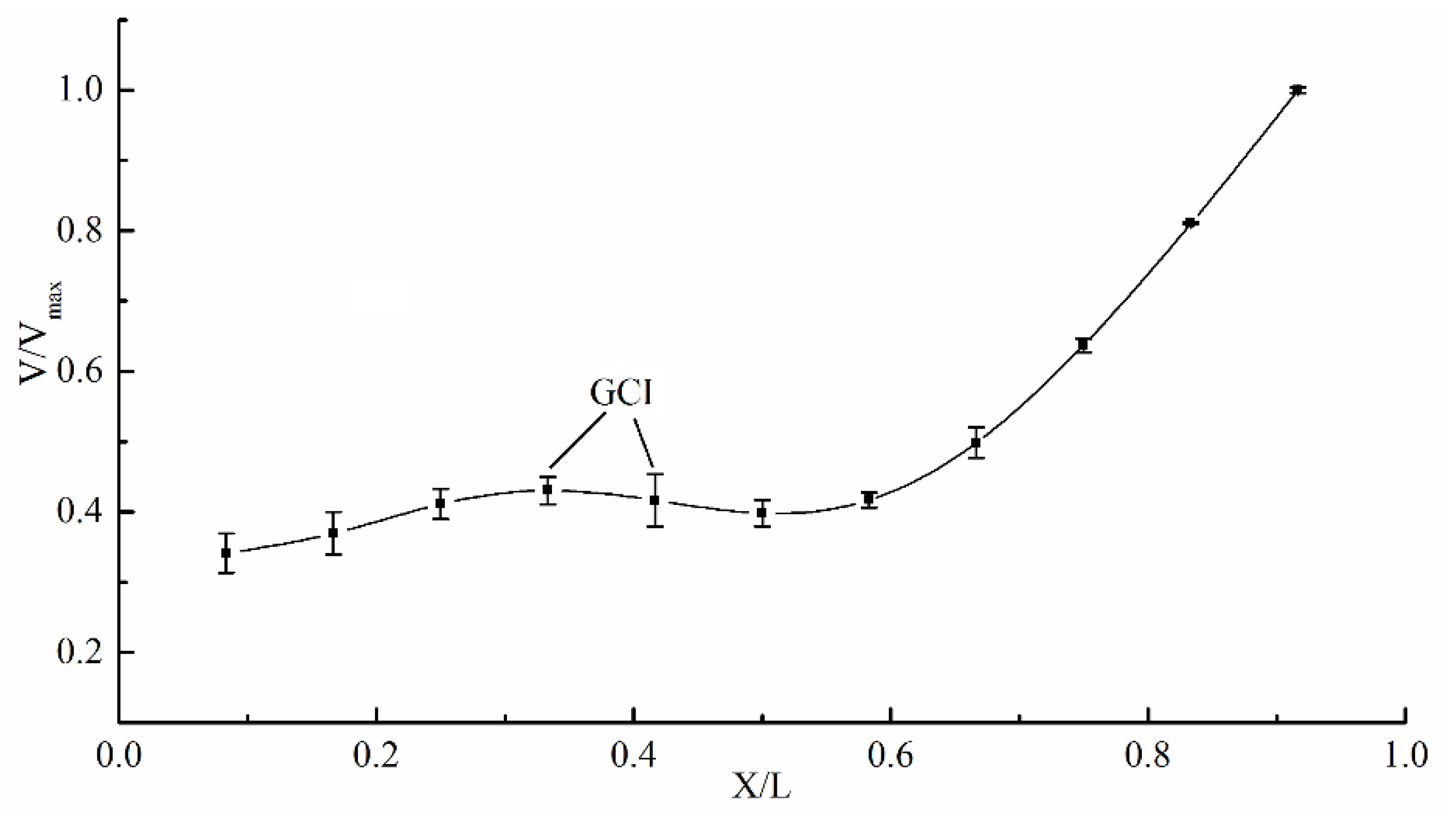
The grid convergence index (GCI) [21] with numbers of approximately 0.25 million, 0.60 million, and 1.95 million was were used to check the sensitivity of the grid in the numerical model. This method was run with Equations (9) and (10), and more details can be found in Celik [21].
G C I = 1.25 | ϕ 1 ϕ 2 ϕ 1 | ( h 2 / h 1 ) P 1
P = 1 ln ( h 2 / h 1 ) | ln | ( ϕ 3 ϕ 2 ) / ( ϕ 2 ϕ 1 ) | + ln ( ( h 2 / h 1 ) P sgn ( ( ϕ 3 ϕ 2 ) / ( ϕ 2 ϕ 1 ) ) ( h 3 / h 2 ) P sgn ( ( ϕ 3 ϕ 2 ) / ( ϕ 2 ϕ 1 ) ) ) |
where, ϕ i is the solution for the ith grid, i is the selected numerical value, and hi is the grid size. In this paper, three representative grids with 0.25 million, 0.60 million, and 1.95 million were used to calculate the GCI.
The calculation model of the horizontal face angle (θ = 30°) was chosen and the effect of the grid sizes on the uncertainty of the computational velocity distribution is shown in Figure 2, where the horizontal axis is the dimensionless velocity and the horizontal axis represents the dimensionless width of the step in the position of Z/B = 0.25. As shown in Figure 2, the maximum uncertainties in the velocity were approximately 7.3%. Thus, 0.60 million was chosen in this paper.
In order to test the accuracy of the numerical values, physical model experiments were made in the State Key Laboratory of Hydraulic and Mountain River Engineering, Sichuan University, Chengdu. This model was composed of an upper water tank, a stepped spillway (including transitional section and a stepped section), a tail water section, a measuring weir, and a reservoir. The size of the stepped spillway and the unit discharges were identical to those of the numerical model. Two horizontal face angles (θ = 15°, 30°) were chosen in the physical model experiments and the validation model is shown in Figure 3. Figure 3a–c is the physical model, the layout of model, and the layout of the pressure measurement point, respectively.
Table 1 and Table 2 show a comparison of the pressures between the numerical and physical values on the horizontal surface and vertical surface, respectively. Here, X represents the distance of the pressure detecting points on the horizontal surface from the step’s inner edge, L represents the length of the step, Y represents the distance of the pressure detecting points on the vertical surface from the step’s lower edge, and H represents the height of the step. Table 3 features a comparison of the energy dissipation rates between numerical and physical values with various unit discharges. As seen in Table 1, Table 2 and Table 3, the maximum error of the pressure on the horizontal surface was 7.94%, the maximum error of the pressure on the vertical surface was 7.41%, and the maximum error of the energy dissipation rates was 6.7%. Although there were some errors, the accuracies were sufficient.

3. Results and Discussion

3.1. Streamlines

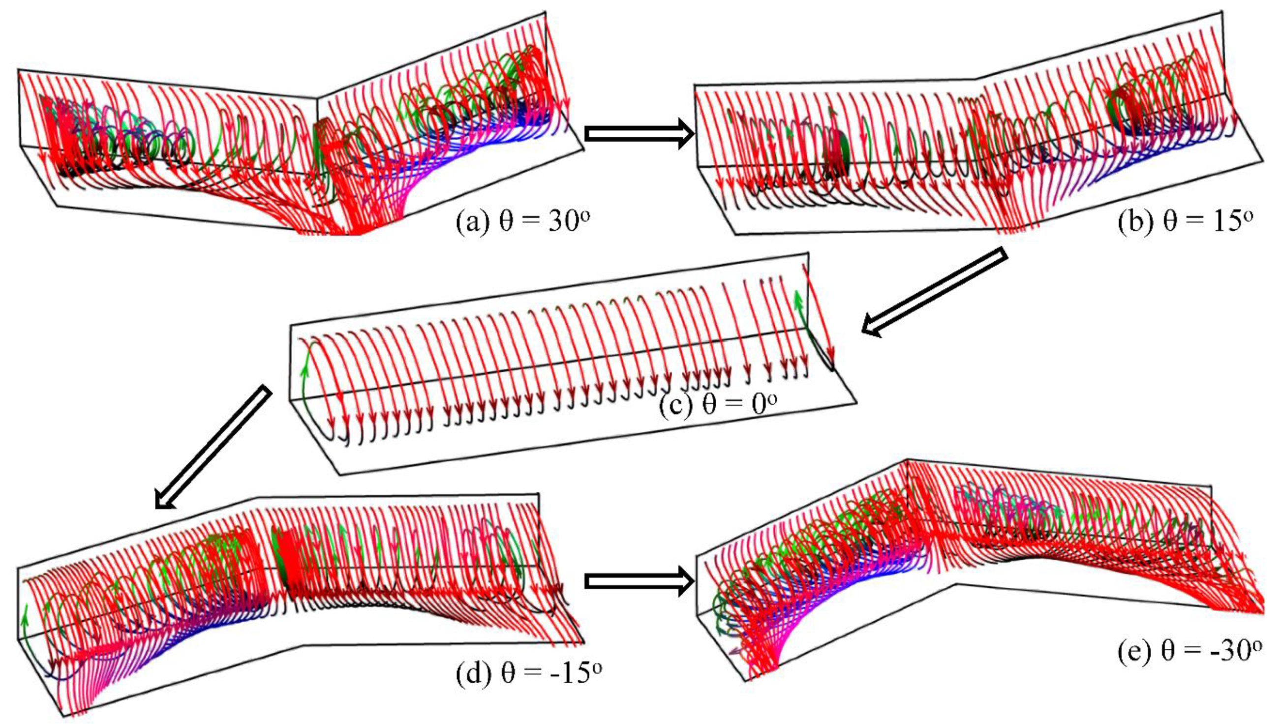
The direction of velocity, the basic characteristic in a V-shaped stepped spillway, varies greatly, and an analysis of streamlines helps us to understand the effects of energy dissipation of the stepped spillway in-depth. Figure 4 shows the streamlines of differently shaped steps for a one-step number (#43, for example). It can be seen that (1) when θ = 0°, the streamlines were parallel to the axial plane, so the free water surface did not change along the cross-section; (2) when θ > 0°, the streamlines were not parallel to the axial plane and extended from the sidewalls to the axial plane, so the water flow collided near the axial plane. However, the body of the stepped spillway with θ = 30° became larger than that in the stepped spillway with θ = 15°, so the collision of the water flow near the axial plane was more intense; and (3) when θ < 0°, the streamlines were also not parallel to the axial plane and extended from the axial plane to the sidewalls, so the water flow from the axial plane collided with the sidewalls. As a result, the free water surface would be higher near the sidewalls. However, the body of the stepped spillway with θ = −30° became larger than that in the stepped spillway with θ = −15°, so the collision of the water flow near the sidewalls was more intense.

3.2. Energy Dissipation Rate

As a result of the conservation of upstream and downstream energy, the ratio of the energy loss to the upstream energy is defined as the energy dissipation rate:
η = Δ E E 1 × 100 % = E 1 E 2 E 1 × 100 %
where E 1 , E 2 are the total energy in the beginning and end of the stepped section, respectively; E 1 = Δ h + v 1 2 / ( 2 g ) , E 2 = v 2 2 / ( 2 g ) ; where Δ h is the difference in the height between the two sections, and v 1 and v 2 are the average velocities in the two sections.
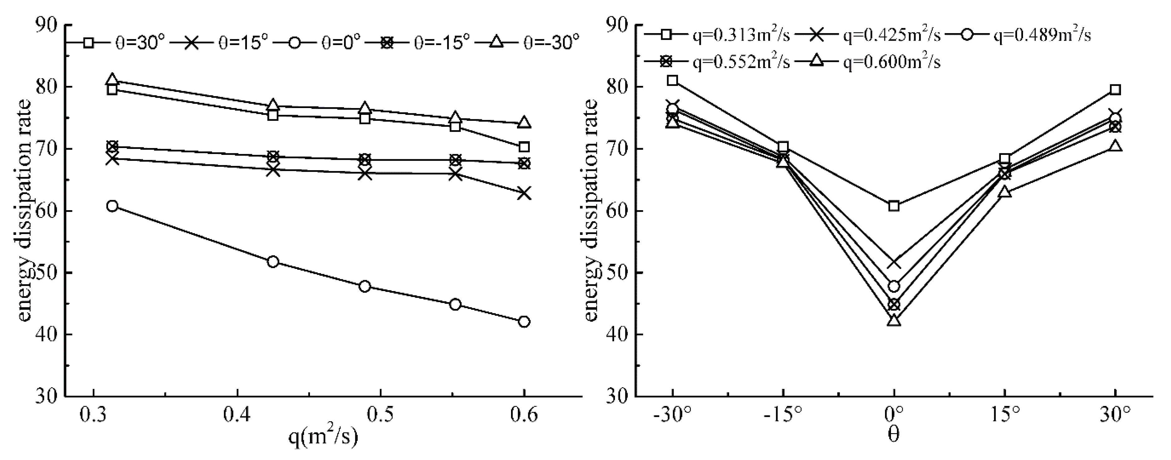
Figure 5 shows the energy dissipation rates change with various unit discharges and horizontal face angles. It can be seen that (1) the energy dissipation rates in all shaped stepped spillways decreased with an increase of the unit discharges but the decrement rate was larger in the traditional stepped spillway; and (2) at a given unit discharge, as the angle increased, the energy dissipation rate initially decreased and then increased. Thus, the energy dissipation rate was the lowest in the traditional stepped spillway.

3.3. Turbulence Kinetic Energy (k) and Its Dissipation Rate (ε)

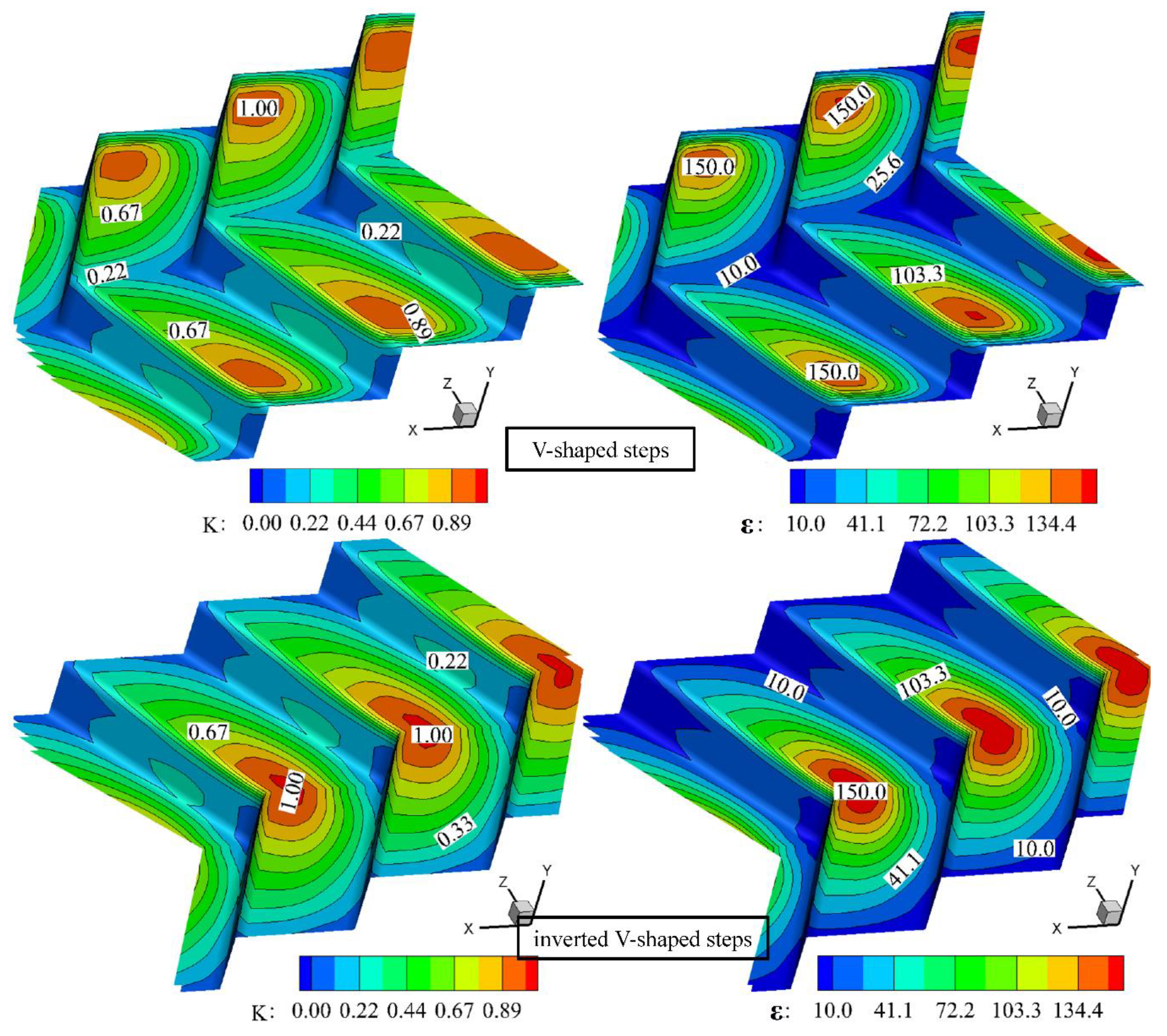
Figure 6 shows the distribution of turbulence kinetic energy and its dissipation rate on the stepped surface of the V-shaped and inverted V-type step spillways, respectively. In this paper, the turbulent kinetic energy and dissipation rate from the 1-mm position to the wall were selected for analysis. It can be seen that obvious changes, which were shown on the step surface of the V-shaped and inverted V-shaped steps, appeared along the width of the spillway. The maximum of turbulence kinetic energy and its dissipation rate for the V-shaped step were found in the stepped horizontal plane in the vicinity of the side wall. However, those for the inverted V-shaped step were presented in a stepped horizontal plane near the central axis, from which a distinct three-dimensional feature is shown.
For the V-shaped step, the maximal turbulence kinetic energy appears on the stepped horizontal plane near the side wall because the water flow, falling near the side wall and moving to the central axis surface by swirling, intensified the turbulence on the step surface. At the same time, the energy loss caused by this collision was also greater than the others, so its dissipation rate also reached its maximum in the vicinity of the side wall. However, for the inverted V-shaped step, the maximum of the turbulence kinetic energy and its dissipation rate were shown in the stepped horizontal plane near the central axis, where the water fell into the central axis from the sidewall. The distribution of the turbulence kinetic energy and its dissipation rate showed a certain symmetry due to the symmetry of the structure for the V-shaped step and inverted V-shaped step.
Figure 7 shows the changes of the ratio of turbulence kinetic energy and its dissipation rate with different unit discharges and horizontal face angles. In this figure, kmax and εmax indicate the maximum turbulence kinetic energy and its maximum dissipation rate in the corresponding calculation conditions, respectively; εmax/kmax indicates the ratio of its dissipation rate and turbulence kinetic energy, which can reflect the changes in energy dissipation rates because when the unit discharge is larger and has a more complex structure caused by horizontal face angles, the turbulence kinetic energy and the its dissipation rate are larger for the increasing fluctuating velocity.
As is shown in Figure 7a, in all shaped stepped spillways, εmax/kmax decreased with an increase of the unit discharge. This suggests that the increase of the dissipation rate was less than that of the turbulence kinetic energy due to their increase in unit discharges. Therefore, the energy dissipation rates decreased with the increasing of the unit discharge.
As shown in Figure 7b, a given unit discharge with increasing angles, the εmax/kmax, initially decreased and then increased. The minimum εmax/kmax was observed at θ = 0°, which is slightly smaller in a stepped spillway with θ > 0° than that in a stepped spillway with θ < 0° for equal absolute values of the angles. Thus, with increasing horizontal face angles, the energy dissipation rates initially decreased and then increased and were slightly smaller in a stepped spillway with θ > 0° than that in a stepped spillway with θ < 0° for equal absolute values of the angles, as shown in Figure 5.

4. Conclusions

This paper investigated the effects of varying horizontal face angles on energy dissipation rates by comparing the flow field, energy dissipation rates, turbulence kinetic energy, and turbulence dissipation rate with different horizontal face angles. The conclusions obtained are as follows:
(1)
The fluctuation of a free water surface will be larger with the larger absolute values of the angles in the V shaped stepped spillway. The fluctuations will be higher in the vicinity of the axial plane or sidewalls for θ > 0° or θ < 0°.
(2)
The energy dissipation rate increases with the absolute values of the horizontal face angles and decreases as the unit discharge increases. The energy dissipation rate of the traditional stepped spillway is the minimum in all kinds of stepped spillways.
(3)
The flow field and the flow direction can be changed by the horizontal face angles of the stepped spillway, which produces some unique characteristics, such as unique vortex structures, which can cause better energy dissipation. These results will be useful in choosing a better stepped spillway for energy dissipation.

Author Contributions

Conceptualization, Y.P. and H.Y.; Data curation, X.Z., X.L., C.X., S.Y. and Z.B.; Formal analysis, H.Y.; Methodology, H.Y. and C.X.; Project administration, Y.P. and X.Z.; Resources, X.L.; Supervision, X.Z. and Z.B.; Writing—original draft, Y.P. and H.Y.; Writing—review and editing, Y.P. and H.Y.

Funding

This project was supported by the National Natural Science Foundation of China (Grant No. 51709293).

Conflicts of Interest

The authors declare no conflict of interest.

Nomenclature

Bmodel width
gacceleration of gravity
GCIGrid convergence index
Hheight of the step
inumber of Grid in GCI
kturbulence kinetic energy
Llength of the step
Ppressure
qunit discharge
ttime
vvelocity
Xdistance of the pressure detecting point on horizontal surface from the step’s inner edge
Ydistance of the pressure detecting points on vertical surface from the step’s lower edge
C2empirical constant
C u 0.09
C 1 ε 1.44
C 2 ε 1.92
E1total energy in the first step of a stepped section
E2the total energy at a section below the stepped section
G b turbulent energy caused by average velocity gradient
G k turbulent energy caused by lift force
higrid size in GCI
kmaxmaximum turbulence kinetic energy
S K user-defined source item
S ε user-defined source item
uimean velocity component in the ith direction
v 1 average velocities in the first step of a stepped section
v 2 average velocities in a section below the stepped section
Y M contribution of compressible turbulent fluctuation expansion to overall dissipation rate
εturbulence dissipation rate
μdynamic viscosity
θhorizontal face angle
ηenergy dissipation rate
ρmean density
ρ a densities of air
ρ w densities of water
α w volume fraction of water
εmaxmaximum turbulence dissipation rates
μ a viscosities of air
μ w viscosities of water
σ k empirical constant,1.0
σ ε empirical constant
ϕ i solution about the ith grid
Δ h difference in height between two sections
ΔEdifference in energy between two sections

References

  1. Anwar, N.; Dermawan, V. Physical hydraulic model investigation of flow and energy dissipation on smooth and stepped spillway with steep slope. Int. J. Acad. Res. 2011, 3, 727. [Google Scholar]
  2. Felder, S.; Chanson, H. Energy dissipation down a stepped spillway with non-uniform step heights. J. Hydraul. Eng. 2011, 137, 1543–1548. [Google Scholar] [CrossRef]
  3. Morovati, K.; Eghbalzadeh, A.; Soori, S. Numerical study of energy dissipation of polled stepped spillways. Civ. Eng. J. 2016, 2, 208–220. [Google Scholar] [CrossRef]
  4. Chanson, H. Comparison of energy dissipation between nape and skimming flow regimes on stepped chutes. J. Hydraul. Res. 1994, 32, 213–218. [Google Scholar] [CrossRef]
  5. Abbasi, S.; Kamanbedast, A.A. Investigation of Effect of Changes in Dimension and Hydraulic of Stepped Spillways for Maximization Energy Dissipation. World Appl. Sci. J. 2012, 18, 261–267. [Google Scholar]
  6. Rassaei, M.; Rahbar, S. Numerical flow model stepped spillways in order to maximize energy dissipation using FLUENT software. IOSR J. Eng. 2014, 4, 17–25. [Google Scholar] [CrossRef]
  7. Tabari, M.M.R.; Tavakoli, S. Effects of stepped spillway geometry on flow pattern and energy dissipation. Arab. J. Sci. Eng. 2016, 41, 1215–1224. [Google Scholar] [CrossRef]
  8. Wu, P.; Wang, B.; Chen, Y.L.; Zhou, Q. Energy Dissipation of Skimming Flow over Stepped Chutes with Different Slopes. J. Sichuan Univ. 2012, 44, 24–29. (In Chinese) [Google Scholar]
  9. Shahheydari, H.; Nodoshan, E.J.; Barati, R.; Moghadam, M.A. Discharge coefficient and energy dissipation over stepped spillway under skimming flow regime. KSCE J. Civ. Eng. 2015, 19, 1174–1182. [Google Scholar] [CrossRef]
  10. Attarian, A.; Hosseini, K.; Abdi, H.; Hosseini, M. The effect of the step height on energy dissipation in stepped spillways using numerical simulation. Arab. J. Sci. Eng. 2014, 39, 2587–2594. [Google Scholar] [CrossRef]
  11. Zhang, Z.C.; Zeng, D.Y.; Liu, Y.F. Expermiental Research on the Presented Water-Surface Curve of Skmiming Flow on Stepped Spillways and Energy Disspation. Chin. J. Appl. Mech. 2005, 22, 30–36. (In Chinese) [Google Scholar]
  12. Guenther, P.; Felder, S.; Chanson, H. Flow aeration, cavity processes and energy dissipation on flat and pooled stepped spillways for embankments. Environ. Fluid Mech. 2013, 13, 503–525. [Google Scholar] [CrossRef]
  13. Mero, S.; Mitchell, S. Investigation of energy dissipation and flow regime over various forms of stepped spillways. Water Environ. J. 2016, 31, 127–137. [Google Scholar] [CrossRef]
  14. Barani, G.A.; Rahnama, M.B.; Sohrabipoor, N. Investigation of flow energy dissipation over different stepped spillways. J. Phys. Chem. C 2005, 117, 7123–7137. [Google Scholar]
  15. Jahad, U.A.; Al-Ameri, R.; Das, S. Energy dissipation and geometry effects over stepped spillways. Int. J. Civ. Eng. Technol. 2016, 7, 188–198. [Google Scholar]
  16. Tian, Z.; Xu, W.L.; Yu, T.; Zhou, H.H.; Xiao, F.R. Characteristics of Energy Dissipation for V shaped Stepped Spillway. J. Sichuan Univ. 2010, 42, 21–25. (In Chinese) [Google Scholar]
  17. Shih, T.H.; Liou, W.W.; Shabbir, A.; Yang, Z.; Zhu, J. A new k-ε eddy viscosity model for high Reynolds number turbulent flows. Comput. Fluids 1995, 24, 227–238. [Google Scholar] [CrossRef]
  18. Qian, Z.D.; Hu, X.Q.; Huai, W.X.; António, A. Numerical simulation and analysis of water flow over stepped spillways. Sci. China Technol. Sci. 2009, 52, 1958–1965. (In Chinese) [Google Scholar] [CrossRef]
  19. Duangrudee, K.; Chaiyuth, C.; Pierre, Y.J. Numerical simulation of flow velocity profiles along a stepped spillway. Inst. Mech. Eng. 2014, 227, 327–335. [Google Scholar]
  20. Bai, Z.L.; Zhang, J.M. Comparison of different turbulence models for numerical simulation of pressure distribution in v-shaped stepped spillway. Math. Probl. Eng. 2017, 2017, 1–9. [Google Scholar] [CrossRef] [Green Version]
  21. Celik, I.B.; Ghia, U.; Roache, P.J.; Freitas, C.J. Procedure for estimation and reporting of uncertainty due to discretization in CFD applications. J. Fluids Eng. 2008, 130, 078001. [Google Scholar]
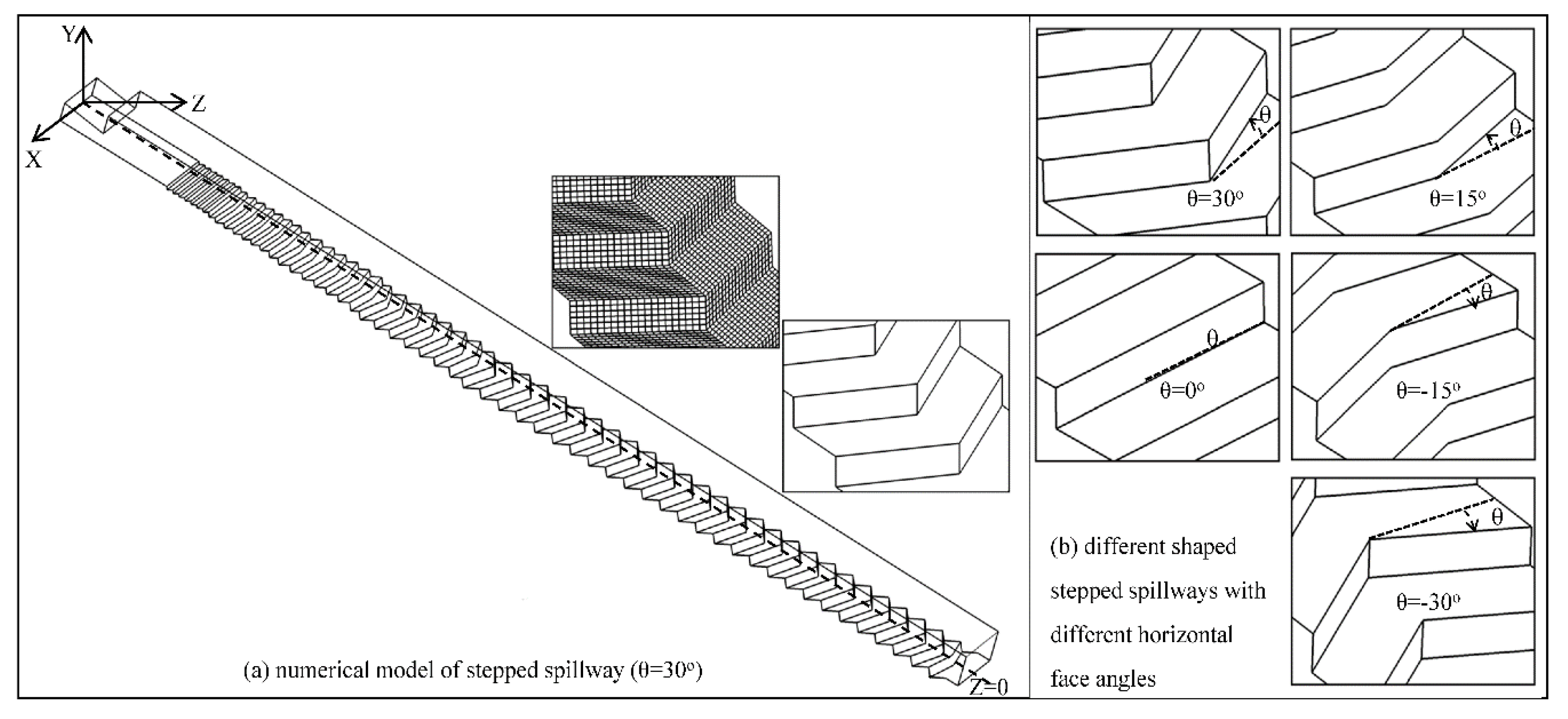
Figure 1. Layout of the numerical model.
Energies 12 04469 g001
Figure 2. Grid convergence (GCI) values for different grid densities with velocity.
Energies 12 04469 g002
Figure 3. Layout of the validation model.
Energies 12 04469 g003
Figure 4. Streamlines of different shaped steps (#43).
Energies 12 04469 g004
Figure 5. Energy dissipation rate changes with various unit discharges (left) and horizontal face angles (right).
Energies 12 04469 g005
Figure 6. The distribution of turbulence kinetic energy (left) and its dissipation rate (right) on the stepped surface of V-shaped and inverted V-type step spillways (q = 0.425 m2/s).
Energies 12 04469 g006
Figure 7. The changes of the ratio of its dissipation rate and turbulence kinetic energy with different unit discharges (a) and horizontal face angles (b).
Energies 12 04469 g007
Table 1. Comparison of the pressures between the numerical and physical values on the horizontal surface (q = 0.489 m2/s, θ = 30°).
X/LX/B = 0X/B = 0.25X/B = 0.5
Physical Numerical Error (%)Physical Numerical Error (%)Physical NumericalError (%)
0.08−7.02−7.587.948.028.586.9513.3913.34−0.37
0.17−9.48−9.934.763.804.046.2312.7013.123.34
0.25−12.72−13.183.561.401.464.1512.8013.112.43
0.33−15.48−14.45−6.653.423.22−5.7614.0513.30−5.35
0.42−11.04−11.837.198.218.463.1414.2413.67−4.01
0.50−2.20−2.377.4515.0815.231.0314.9914.09−6.01
0.5811.6712.426.4122.4821.64−3.7215.1714.35−5.43
0.6731.6532.873.8527.9826.28−6.0814.4414.22−1.53
0.7551.9252.661.4130.6328.53−6.8614.5713.65−6.30
0.8361.0863.153.3931.2428.86−7.6213.4012.64−5.68
0.9260.5757.25−5.4727.3225.72−5.8811.8511.19−5.59
Table 2. Comparison of the pressures between the numerical and physical values on the vertical surface (q = 0.489 m2/s, θ = 30°).
Y/HX/B = 0X/B = 0.25 X/B = 0.5
PhysicalNumericalError (%)PhysicalNumericalError (%)PhysicalNumericalError (%)
0.83−23.94−25.707.35−3.31−3.536.868.167.65−6.21
0.67−11.58−12.336.54−1.49−1.554.358.688.49−2.14
0.50−10.48−11.257.41−2.84−2.64−7.098.909.031.39
0.33−9.12−9.473.831.491.606.9510.7110.39−3.01
0.17−7.61−7.26−4.488.959.566.8211.9212.373.70
Table 3. Comparison of the energy dissipation rates between the numerical and physical values with various unit discharges.
Caseθ = 30°
q(m2/s)Physical ValueNumerical ValueError (%)
0.31375.2179.565.78
0.42573.2175.392.98
0.48970.1474.846.70
0.55269.2473.566.24
0.60067.7670.243.66