Article

Metallic Organic Framework-Derived Fe, N, S co-doped Carbon as a Robust Catalyst for the Oxygen Reduction Reaction in Microbial Fuel Cells

College of Chemistry & Environmental Engineering, Yangtze University, Jingzhou 434000, China
*
Author to whom correspondence should be addressed.
Energies 2019, 12(20), 3846; https://doi.org/10.3390/en12203846
Submission received: 22 August 2019 / Revised: 27 September 2019 / Accepted: 30 September 2019 / Published: 11 October 2019

Abstract

:
Oxygen reduction reaction (ORR) provides a vital role for microbial fuel cells (MFCs) due to its slow reaction kinetics compared with the anodic oxidation reaction. How to develop new materials with low cost, high efficacy, and eco-friendliness which could replace platinum-based electrocatalysis is a challenge that we have to resolve. In this work, we accomplished this successfully by means of a facile strategy to synthesize a metallic organic framework-derived Fe, N, S co-doped carbon with FeS as the main phase. The Fe/S@N/C-0.5 catalyst demonstrated outstandingly enhanced ORR activity in neutral PBS and alkaline media, compared to that of commercial 20% Pt-C catalyst. Here, we started-up and operated two parallel single-chamber microbial fuel cells of an air cathode, and those cathode catalysts were Fe/S@N/C-0.5 and commercial Pt-C (20% Pt), respectively. Scanning electron microscopy (SEM) elaborated that the Fe/S@N/C-0.5 composite did not change the polyhedron morphology of ZIF-8. According to X-ray diffractometry(XRD) curves, the main crystal phase of the resulted Fe/S@N/C-0.5 was FeS. The chemical environment of N, S, and Fe which are anticipated to be the high-efficiency active sites of ORR for MFCs were investigated by X-ray photoelectron spectroscopic(XPS). Nitrogen adsorption/desorption techniques were used to calculate the pore diameter distribution. In brief, the obtained Fe/S@N/C-0.5 material exhibited a pronounced reduction potential at 0.861 V (versus Reversible Hydrogen Electrode(RHE)) in 0.1M KOH solution and –0.03 V (vs. SCE) in the PBS solution, which both outperform the benchmark platinum-based catalysts. Fe/S@N/C-0.5-MFC had a higher Open Circuit Voltage(OCV) (0.71 V), stronger maximum power density (1196 mW/m2), and larger output voltage (0.47 V) than the Pt/C-MFC under the same conditions.

1. Introduction

Recently, due to the increasing concern about the shortage of energy and the pollution of the environment, it has become inevitable to develop environmentally friendly and renewable energy plants such as Zn–Air batteries, fuel cell and lithium–air batteries, etc. [1,2,3,4,5]. Electrochemical reactions are an important process in which oxygen reduction reaction (ORR) plays a vital role. Because ORR is a bottleneck having slow reaction kinetics, and thus, efficiency of ORR depends heavily on the catalyst used [6,7,8]. It is also one of the obstacles in microbial fuel cells (MFCs) whose electron acceptor is oxygen, and the research of cathode catalysts has also become a hot spot [9]. In an MFC, electrochemically active bacteria attached to the anode electrode provide electrons while oxidizing organic matter, and the resulting electrons flow from the anode through a wire to the cathode producing an electric current. Electron acceptors are reduced on a cathode during the reaction. MFCs have great development potential compared with other fuel cells because they can generate electricity by microbial reactions while removing organic pollutants in wastewater [10]. Organic matters such as glucose, peptone, and sodium acetate are consumed as a nutritious source for the microbial community at the anode, and oxygen reduction reaction (ORR) occurs at the cathode. So far, the state-of-the art platinum or alloyed platinum noble metal materials have shown excellent performance in ORR, but the weakness is obvious. Their intolerable cost, low reserves, inferior durability, and also the issue of methanol crossover have severely handicapped the application of the new devices [11]. Therefore, developing new, efficient, cheap, and stable non-noble metal composite catalysts is important [12]. Some transition metals (Fe, Co, Mn), which have to a certain extent exhibited catalytic activity for ORR, have attracted many researchers’ attention. Especially, a variety of transition metal compounds, such as carbides/nitrides, oxides, and chalcogenides, showing good stability in ORR have been studied already [13,14,15]. Unfortunately, the performance of the transition metals-based catalysts is not satisfactory in acidic media. In order to solve this problem, many solutions have been proposed. Transition-metal-coordinating the doping of heteroatom (S, P, N) carbon-based materials demonstrated good activity and stability in ORR, especially in acidic medium [16,17]. Zhong et al. reported a facile approach for the in situ anchoring of CO9S8 nanoparticles on nitrogen and sulfur co-doped porous carbon as an efficient catalyst for ORR, showing a high catalytic performance. Furthermore, manganese dioxide (MnO2) was reported to be a promising electrocatalyst which was efficient in ORR activities and could generate a high power output in air cathode MFCs. In addition, a class of Co-MOF-derived dual metal and nitrogen co-doped carbon (Ni, Fe, Zn, and Cu) catalysts were also studied, which were highly porous, with metal and nitrogen uniformly distributed within the graphite carbon matrix, and exhibited the best ORR performance [18,19]. Along with these, carbides derived from Fe-based MOFs were studied extensively as a potential candidate to replace Pt-based catalysts [20], due to their long-term stability and excellent activity in medium [21,22,23]. The active sites originating from transition-based MOFs tend to form special pore structures on the carbon matrix [24,25]. Various metal organic frameworks (MOFs) have been widely exploited as nano-material sources with a controllable structure for electrochemical equipment [26,27,28]. Lou’s group found that N-doped CNTs can be transformed by the precursor zif-67 possessing high electrochemical catalytic activity after carbonization in H2 atmosphere [29]. The precursors of N-sources mainly concentrate on polyaniline, thiourea, carbamide, and polypyrrole. Many researchers also showed immense enthusiasm for introducing other heteroatoms (S, P, B) into MOFs. Among them, the sulfur-doped catalyst was more positively correlated with ORR activity, compared with nitrogen. As the sulfur atom has a larger radius, it could bring some chemical structural defects of the carbon matrix accelerating electron transfer and oxygen adsorption [30,31]. For example, Liu’s group [32] synthesized N and S co-doping porous carbon materials decorated with FeS and demonstrated the catalysts own prominent ORR activity, favorable stability, and excellent tolerance to methanol. Wang et al. [33] proved that FeS and Fe9S10 nanoparticles are essential for ORR. These studies confirm that FeS nanoparticles, as a kind of material introducing Fe, S, and N into the carbon matrix, can significantly enhance ORR activity and provide a wider idea and prosperity for developing materials which could replace precious metal-based electrocatalysis.
Considering the catalytic advantages of the type just described, many research groups have focused their attention on the exploration of using transition metal-based catalysts such as iron, cobalt, and manganese with low prices and large amounts available to improve the cathode performance of MFC. In particular, iron-based catalysts are currently the ones used extensively in MFC equipment [34,35,36,37,38,39,40,41]. Carlo’s group designed a kind of Fe-N-C oxygen reduction reaction catalyst for microbial fuel cells. Tang’s group reported the synthesis of a series of transition metal-based catalysts, namely M/CoNC, and that corresponding equipment (MFC) achieved a remarkable power density and outstanding durability.
Herewith, we obtained a batch of catalysts named Fe/S@N/C-x (x = 0.5, 0.33, 0.25). A series of precursors (Fe-encapsulated ZIF-8 carbon materials) were directly synthesized, and the content of Fe was controlled in the precursor by adjusting the proportion of Fe and Zn of the raw material, followed by the introduction of a certain amount of thiourea as a sulfur source under the atmosphere of 1000 °C. In the preparation process, Zn was removed at a high temperature (1000 °C) and then etched by HCl. The obtained Fe/S@N/C-0.5 catalyst had a regular structure containing both large numbers of micropores and mesopores, and Fe, N, S uniformly distributed among the material. FeS is the main phase which was investigated and characterized via XRD and XPS. The Fe, N, and S co-doped Fe/S@N/C-0.5 catalyst exhibits surprising ORR activity in alkaline and neutral phosphate buffered saline(PBS) media, with a remarkable reduction potential at 0.861 V (vs. RHE) in 0.1 M KOH solution and –0.03 V (vs. SCE) in the PBS solution. The performance of microbial fuel cells (MFCs) employing the Fe/S@N/C-0.5 as a cathode catalyst was tested as well. We confirm that the prepared Fe/S@N/C-0.5 could greatly improve the performance of microbial fuel cells (MFCs), and the Fe/S@N/C-0.5-MFC possesses larger energy and power density compared with Pt/C-MFC under the same conditions.

2. Experimental

2.1. Sample Preparation

This section simply gives a brief introduction on how to acquire the Fe, N, and S co-doped Fe/S@N/C-x (x = 0.5, 0.33, 0.25) catalyst. The Fe/S@N/C-x (x = 0.5, 0.33, 0.25) catalyst, derived from porous metal organic framework-encapsulated iron (Fe-ZIF-8), is easily obtained. This synthesis technique has many advantages, such as being simple to operate and the high purity of products. Firstly, Fe3+, Zn2+, and 2-methylimidazole are mixed at room temperature using methanol as a solvent to obtain the precursor. After pyrolysis at a high temperature, the original porous framework was maintained and a nano-composite coated with metal nanoparticles (Fe) was obtained. Secondly, the surface agglomerated iron particles and unstable phases were removed by etching with hydrochloric acid, and new pores were formed at the same time. Lastly, at a high temperature, the thiourea was used as the sulfur source to introduce S atoms into materials; simultaneously, the pyrolysis of thiourea produced gas, which further created new pores and improved the porosity.
The series of precursors were synthesized as follows: A solution of 2.975 g zinc nitrate hexahydrate (Zn(NO3)2·6H2O, > 98%, Sigma Aldrich) and ferric chloride (FeCl3, 1.622 g, 0.811 g, 0.535 g vs. x = 0.5, 0.33, 0.25) dissolved in 80 mL methanol was poured into another solution of 3.284 g 2-methylimidazole (mlm, C4H6N2, > 99%, Sigma Aldrich) dissolved in 50 mL methanol and was stirred for 12 h at 28 °C. The reaction liquid was concentrated with a vacuum rotary evaporator, and then the crude product was obtained by vacuum filtration. Finally, the russet crude product was washed and purified with a mixture of methanol and acetone in a certain proportion and then dried at 60 °C by using the vacuum drying oven for 12 h. The prepared precursor was labeled as Fe-ZIF-8.
For the synthesis of Fe/S@N/C-x (x = 0.5, 0.33, 0.25) catalyst, the precursor was placed on a high-temperature ceramic boat in a furnace and carbonized at 1000 °C for 3 h in N2 atmosphere with a heating rate of 2.5 °C/min. After cooling to room temperature, the product was etched in 0.1 M HCl for 6 h to remove the unstable components and agglomerated iron particles. Then the powder products were washed with deionized water by repeated centrifugations at 5000 rpm until the supernatant was neutral with a pH value of 7. The as etched carbide was mixed well with thiourea by high-energy ball-milling technique, followed by a second calcination at 1000 °C for 1 h in a furnace at the same heating rate as the last calcination (2.5 °C/min). Finally, the product was ground into powder vigorously when cooling it to room temperature. The resultant was referred to as Fe/S@N/C-x (x = 0.5, 0.33, 0.25).

2.2. Characterization of ORR Activity

The electrochemical performances of these catalysts were investigated by employing a CH Instruments 660E electrochemical workstation with a standard three-electrode structure (Pine Instruments, 5.0 mm diameter), and all electrochemical ORR tests were carried out at room temperature (RT, 20–25 °C). The catalyst ink was prepared by ultrasonically dispersing catalyst (5 mg) into 80 µL deionized water, 900 µL isopropanol, and 20 µL nafion solution (5 wt.%) for at least 30 min. The catalyst thin film was gained by removing 21 µL of catalyst ink on the electrode with a pipette. The three-electrode structure was composed with the glassy carbon working electrode (with various prepared catalysts), a platinum electrode (the counter electrode), and a Hg/HgO electrode (reference electrode). The electrode was polished and cleaned according to the instructions of the rotating disc electrode (Pine Instruments): Before the test, the glassy carbon electrodes should be polished with a 0.05 µm Al2O3 particle-suspension on a moistened polishing cloth (Buehler, Micro-Cloth) in a “figure eight” pattern for four minutes to a mirror finish. The polished electrode was rinsed well with nanopure water, sonicated for four minutes in nanopure water, rinsed well again, and then dried at room temperature in air for at least 20 min before use. Cyclic voltammetry curves were obtained in O2-saturated 0.1 M KOH solution at 50 mV/s, and linear sweep voltammetry curves were run at a scan rate of 5 mV/s with rotations at 400, 800, 1200, 1600, and 2000 rpm, respectively. In order to evaluate methanol tolerance, the chronoamperometric curves were received in the O2-saturated solution added with methanol (3 M). The long-time stability was tested at –0.4 V (vs. Hg/HgO) with a rotating rate of 1600 rpm for 20,000 s. In this work, the potential values obtained from all tests in alkaline electrolytes were converted by the calculation to the RHE scale using this transformation equation: E (RHE) = E (Hg/HgO) + 0.866 V in 0.1 M KOH solution.
Herein, the further work and improvement about charge transfer numbers and the kinetic parameters of ORR were operated with the help of the Koutecky–Levich (K-L) equation which is exhibited in Formulas (1) and (2).
1 J = 1 J K + 1 J L = 1 B ω 1 / 2 + 1 J K                
B = 0.2 n F C 0 D 0 2 3 V 1 6    
where J indicates the measured current density, JK shows the kinetic current density, and JL represents the diffusion limiting current density. ω is the rotating speed of RDE (rpm), C (1.2·10−3 cm2·L−1) is the oxygen concentration of 0.1 M KOH electrolyte, D (1.9 × 10⁻⁵ cm2·S−1) is the diffusion coefficient of O2 for 0.1 M KOH solution, and V (1.13 × 10⁻³ cm2·S−1) is the kinetic viscosity of the electrolyte for 0.1 M KOH solution, while F (96485 C·mol−1) is the Faraday constant and n is the calculated charge transfer number.

2.3. Construction of MFC Equipment

2.3.1. Air Cathode Composition

Figure 1 reveals a schematic diagram of the assembled MFC equipment with a carbon felt anode and Fe/S@N/C-0.5 catalyst-loaded carbon paper cathode. The cathode consists of a carbon base layer, catalyst layer, and a total of four PTFE diffusion layers which are directly exposed to the air. The carbon base layer was formed by applying a mixture of carbon black and 40% PTFE emulsion to one side of the carbon paper and then placing the piece of carbon paper on a high-temperature ceramic plate in a pre-heated furnace at 370 °C for about 20–30 min. After cooling the carbon paper to room temperature, a total of four PTFE diffusion layers were obtained by repeating the operation below four times: applying one coat of 60% PTFE emulsion in a uniform fashion to the previously coated side and then leaving it in a furnace preheated to 370 °C for about 10–15 min. Finally, a paste-like mixture of catalyst, deionized water, isopropanol, and naphthol was uniformly applied on the other side of the carbon paper and the coating was allowed to air dry for at least 24 h. The mass loading of the catalyst was 0.5 mg/cm2.

2.3.2. Construction and Operation of MFC

The bacteria in this paper are facultative anaerobic mixed bacteria, which are derived from oil-bearing sludge in the Jianghan oilfield. Firstly, oily sludge was placed in a sealed container under 30 °C for a week and the supernatant was obtained (Figure 2a supporting information). Then, an appropriate amount of supernatant was removed with a pipette and mixed with glucose solution at a ratio of 1:5, and the mixture was transparent at the beginning. We could develop bacteria based on this mixture in an incubator chamber at 37 °C. Finally, as shown in Figure 2b,c, the bacteria used in the microbial fuel cell experiment in this paper were obtained, and the culture medium containing the bacteria was visibly turbid.
We structured the single-chamber microbial fuel cells of the air cathode which was inoculated with oilfield produced water for investigating the performance of the microbial fuel cell (MFC) employing Fe/S@N/C-0.5 as a cathode catalyst. Two completely consistent MFC equipment sets served in experiments which were both about 3 × 3 × 4 cm with 28 mL effective volume. The two MFC devices with 1000 Ω external resistance employed carbon paper cathodes which were supported with Fe/S@N/C-0.5 catalysts and 20% Pt-C respectively (denoted as Fe/S@N/C-0.5-MFC and 20% Pt/C-MFC). Two circular carbon felts were used as anodes for these two MFCs. The felts were successively soaked in acetone solution, 1 M hydrochloric acid solution, and 5 M nitric acid solution for 10 h, then washed with deionized water, and finally dried in the oven at 180 °C for 8 h. Hydrophilic treatments facilitated the adhesion of bacteria on the surface of anodes’ carbon felt. Oilfield-produced water was used as an inoculum. Table 1 is the formulation of the glucose solution which includes glucose (1 g/L), phosphate buffered saline (50 mmol, pH = 7.2), vitamin solutions (5 mL/L), and mineral solutions (12.5 mL/L). The formulations of vitamin and mineral elements are exhibited in Table 2 and Table 3, respectively. During the operation of MFC, the temperature was maintained at 30 °C by using an incubator chamber. After the anode biofilm of a microbial fuel cell matured, the polarization curves, power density curves, and output voltage curves were recorded.

3. Results and Discussion

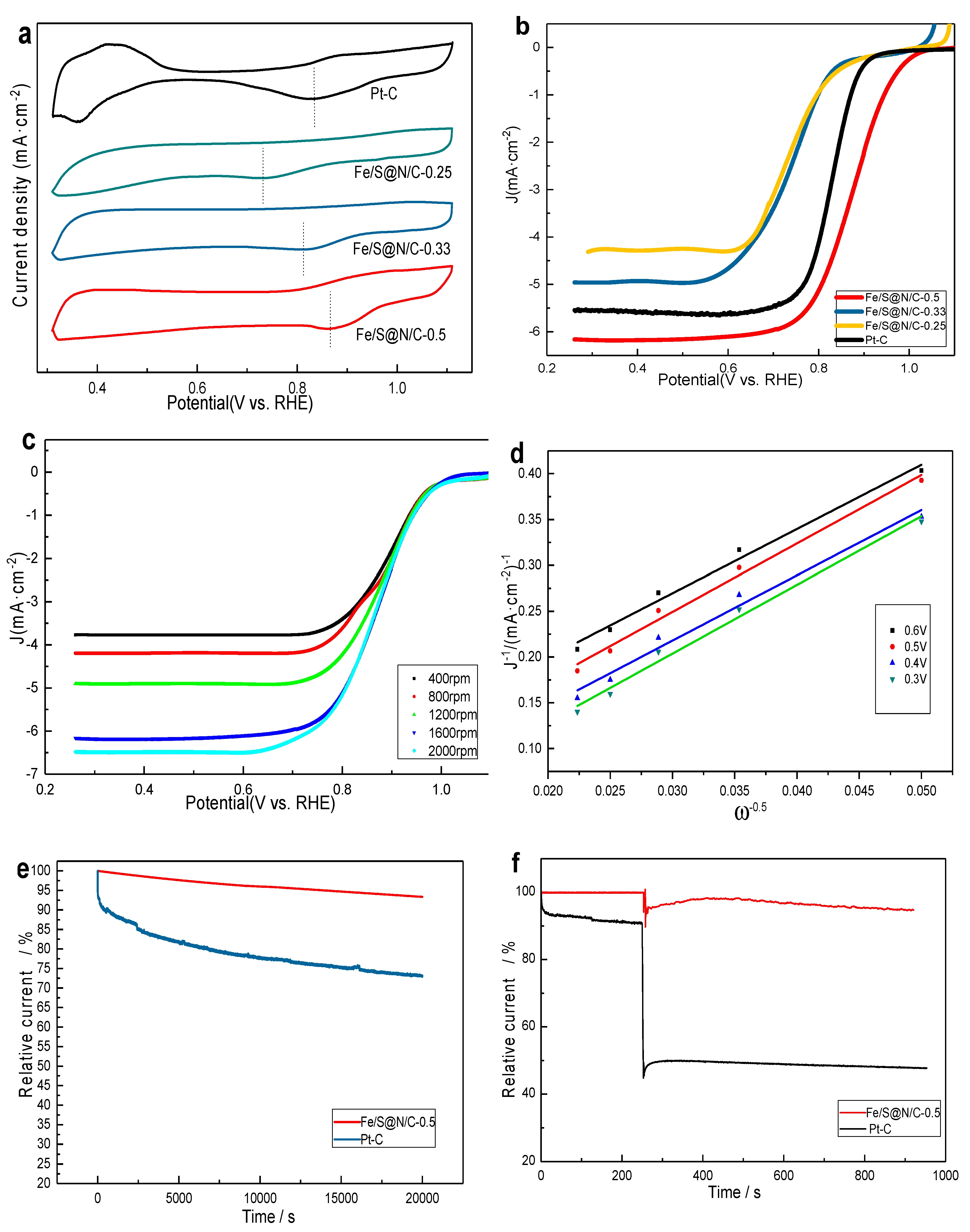
The characterization of ORR activity for as-prepared Fe/S@N/C-x catalysts was estimated in O2-saturated 0.1 M KOH solution, respectively. At a scale of 0.2–1.0 V (vs. RHE), the cyclic voltammetry curves of Fe/S@N/C-x catalysts (Figure 3a) all had a distinct oxygen electro-reduction peak corresponding to a significantly larger current. Those peaks were in the order of Fe/S@N/C-0.25 (E(RHE) = 0.727 V) < Fe/S@N/C-0.33 (E(RHE) = 0.809 V) < Fe/S@N/C-0.5 (E(RHE) = 0.861 V), revealing the Fe/S@N/C-0.5 catalyst showed the most excellent ORR activity which was beyond the commercial Pt-C catalyst (E (RHE) = 0.836 V) [42]. Figure 3b,c demonstrates Linear sweep voltammogram(LSV)curves of Fe/S@N/C-x catalysts operated on RDE to further acquire the four-electron selectivity and kinetic current information, with 20% Pt-C as a reference. The sweep rate at various rotating speeds was 5 mV/s. The half-wave potential (E1/2) of the Fe/S@N/C-0.5 catalyst was 0.87 V, which is 0.13 V and 0.14 V more than Fe/S@N/C-0.33 and Fe/S@N/C-0.25, respectively, while the half-wave potential (E1/2) of the Pt-C catalyst was 0.84 V under the same test conditions. Further, at 1600 rpm, the Fe/S@N/C-0.5 catalyst also has a stronger diffusion-limiting current density (JL) of 6.16 mA·cm−1, which is 1.21, 1.85, and 0.56 mA·cm−1 more than the Fe/S@N/C-0.33, Fe/S@N/C-0.25, and Pt-C catalysts, respectively. In sum, the Fe/S@N/C-0.5 catalyst showed a surprising electro-catalytic activity. Furthermore, by chronoamperometric curve(i-t) tests (Figure 3e), the Fe/S@N/C-0.5 catalyst also showed better long-term stability compared with Pt/C at –0.4 V (vs. Hg/HgO). The current of Fe/S@N/C-0.5 catalyst decreased by less than 7% after 20,000 s, while it fell by 30% in Pt/C. For the methanol tolerance tests (Figure 3f), after methanol injection, the current value of the Fe/S@N/C-0.5 catalyst was almost constant with only subtle variations, while it attenuated greatly in Pt/C.
To better explore the reaction pathway and evaluate the kinetics parameters of the Fe/S@N/C-0.5 catalyst, rotating disk electrode (RDE) test results gave the parameters that depend on the K-L equation. Figure 3c subtly delineates the correlation between the diffusion limiting current density (JL) and the rotational speed. When increasing the rotating rates from 400 to 2000 rpm, the diffusion limiting current density increased, pointing to kinetic-limiting behavior for ORR. In Figure 3d, the Koutecky–Levich (K-L) plots are charted with the values of currents at various rotating rates from 400 to 2000 rpm, and the result has high linearity. In short, the calculated electron transfer number from the slopes of the K-L plots is 3.89 (average value of various potentials) indicating that the Fe/S@N/C-0.5 catalyst works mainly through a four-electron reduction mechanism approximate to the Pt/C catalyst [43].
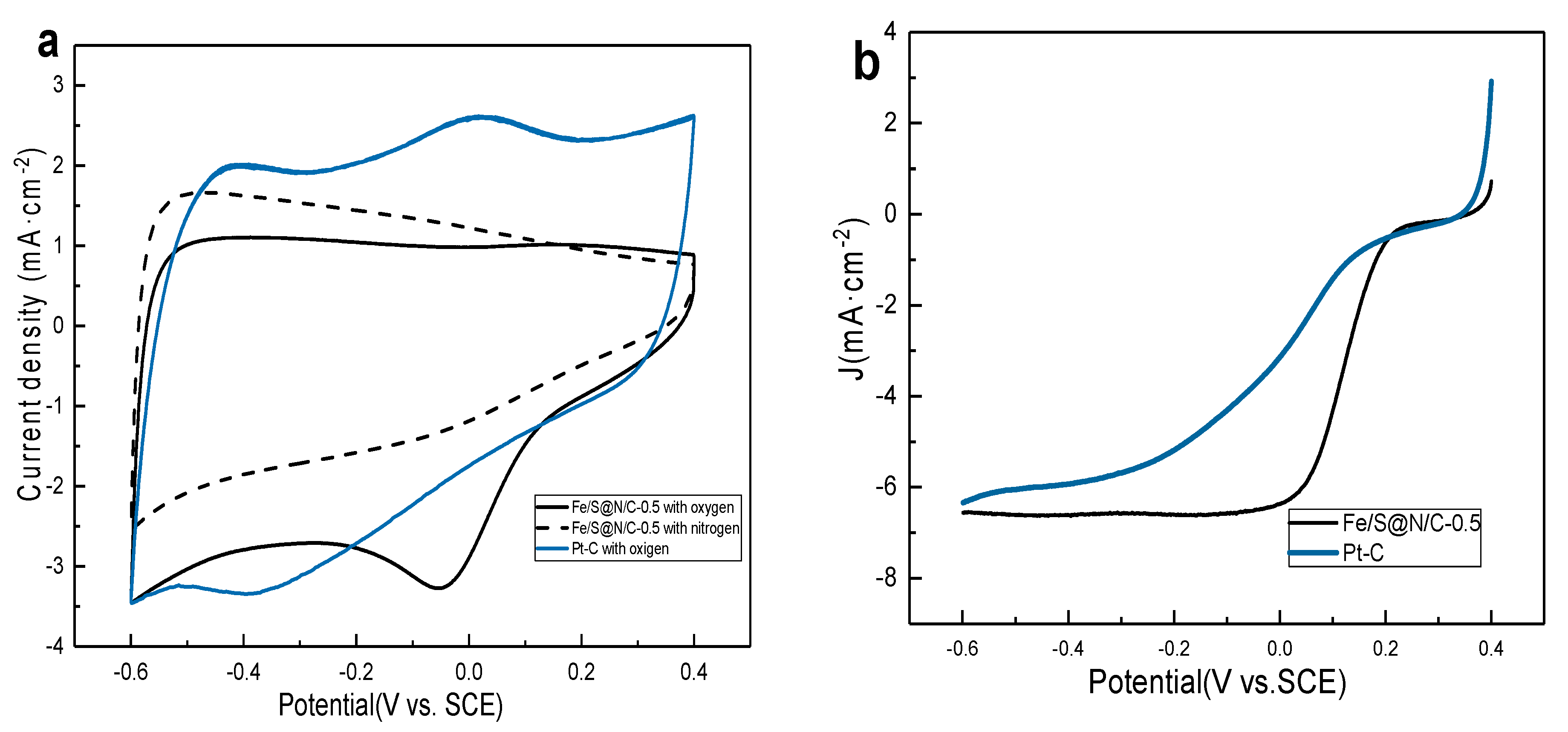
In order to investigate the catalytic activity of Fe/S@N/C-0.5 catalyst on the cathode for MFC, the cyclic voltammetry(CV)curves and LSV measurements were carried out in 0.01 M PBS solution with a pH value of 7 (Figure 4a,b supporting information). Traditionally, neutral PBS solutions are used as electrolytes for biological test systems [44]. As a control, the same experiments could also be done for 20% Pt-C. Figure 4a displays CV curves of Fe/S@N/C-0.5 in O2-saturated (solid line) and N2-saturated (dashed line) 0.01 M PBS solution with commercial 20% Pt-C (tested in O2-saturated 0.01 M PBS solution) as a reference. It is easy to visually observe the response from the ORR. The Fe/S@N/C-0.5 catalyst represents a pronounced cathodic ORR peak at –0.03 V vs. SCE as the PBS solution is saturated with oxygen. In contrast, there is no ORR peak in the nitrogen-saturated electrolyte, indicating that the Fe/S@N/C-0.5 catalyst owns excellent ORR catalytic activity in neutral PBS electrolyte. Rotating disk electrode (RDE) LSV experiments were also conducted in 0.01 M PBS solution for Fe/S@N/C-0.5 catalyst and commercial 20% Pt-C. The comparisons of the results at 1600 rpm are shown in Figure 4b. Encouragingly, compared with commercial 20% Pt-C, there was a more positive onset potential and a stronger limiting current in Fe/S@N/C-0.5 catalyst, which were higher than those of non-noble metal catalysts reported in the recent literature [45], further confirming the excellent ORR performance of the prepared Fe/S@N/C-0.5 catalyst in neutral PBS solution [46].
In order to exploit the electricity generation of Fe/S@N/C-0.5-MFC, the Fe/S@N/C-0.5 catalyst was evaluated in a single-chamber microbial fuel cell of an air cathode for power production and output voltage (Figure 5a,b). The performance of MFC is difficult to directly compare with the results in the literature for many reasons, such as different anode structures, cathode structures, inoculated bacteria strain, components of nutrient solution, and adopted parameters [47]. Therefore, another completely consistent MFC equipment employing the 20% Pt-C as a cathode catalyst was set as a control to clarify that our Fe/S@N/C-0.5 catalyst is a robust catalyst for the oxygen reduction reaction in microbial fuel cells.
The open circuit voltage (OCV) in an MFC is the maximum voltage that could be captured by this power generating units, which is mainly limited by the specific bacterial community and the cathodes. For any power source including MFC, the target is to get the maximum power output, that is, to acquire the strongest current density under the conditions of the highest potential. The output voltage decreases with the decrease of external resistance; therefore, we needed to seek the smallest voltage drop in the process of increasing power density, so as to acquire the maximum power output over the current range of interest, while the polarization curve can be employed to characterize the correlation between current and voltage. This curve demonstrates that the MFC equipment possesses a voltage in the range of the current [48].
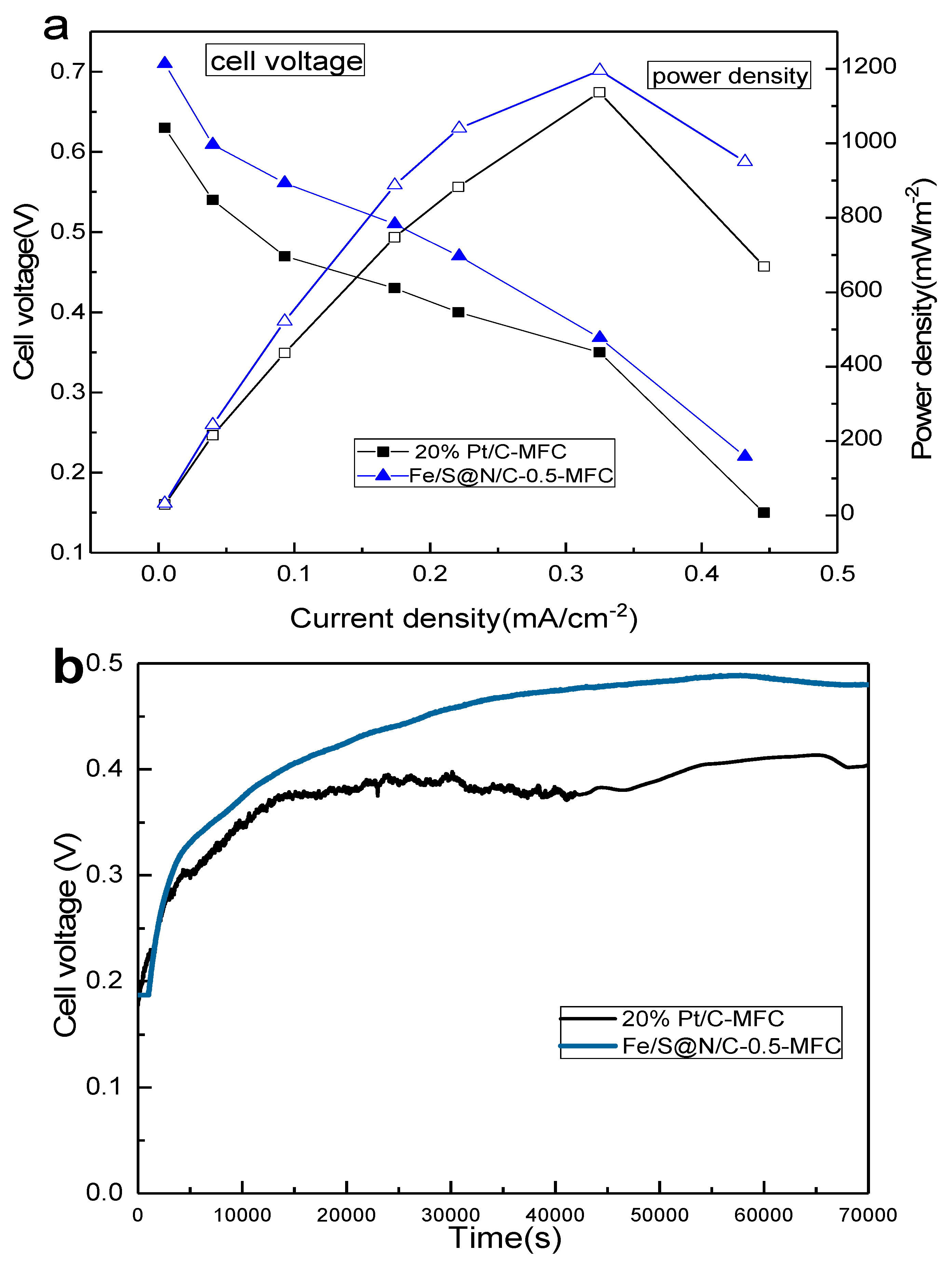
Overall polarization curves and power curves were operated when the open circuit voltage (OCV) was stable within the 1 mV range (Figure 5a). The Fe/S@N/C-0.5-MFC showed an OCV (0.71 V) that is 0.08 V superior compared to the Pt/C-MFC. On the whole, the voltage drop of the Fe/S@N/C-0.5-MFC was smaller than that of the Pt/C-MFC as the current density increased. This adds to the evidence that the Fe/S@N/C-0.5-MFC possesses a higher performance [49]. The power density curves prove the same conclusion, the maximum power density of Fe/S@N/C-0.5-MFC reached up to 1196 mW/m2, while that of Pt/C-MFC was 1137 mW/m2 under the same circumstances. The Fe/S@N/C-0.5-MFC had a 59 mW/m2 higher power density compared to Pt/C-MFC. Figure 5b exhibits the comparisons of the output voltage of these two devices. After these MFCs operated stably, their output voltage was detected. That value of Fe/S@N/C-0.5-MFC (~0.47 V) was 90 mV higher than that of Pt/C-MFC (~0.38 V). The combined abovementioned results indicate that the prepared Fe/S@N/C-0.5 catalyst owns excellent catalytic activity for air cathode MFCs [50].
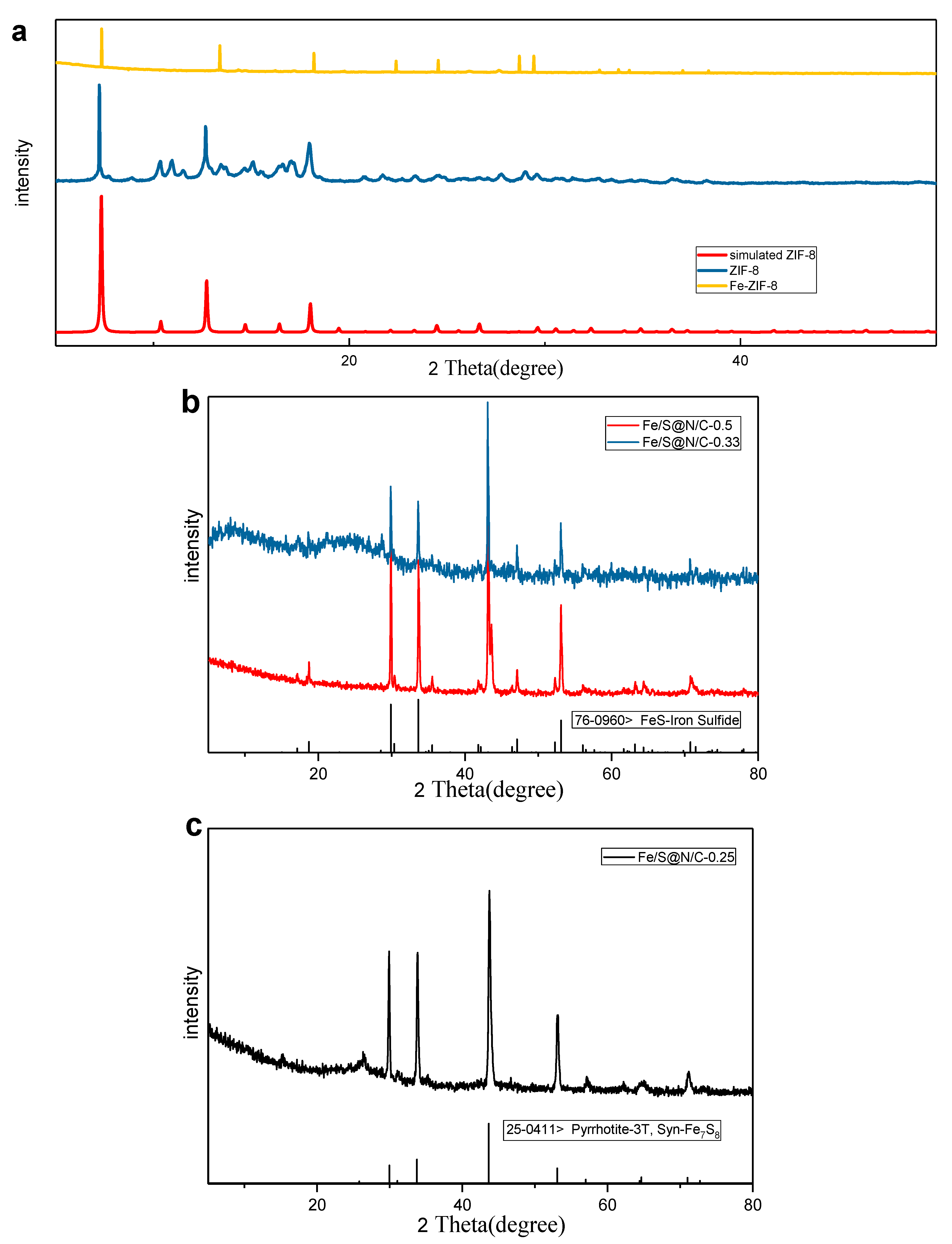
To further examine the physical properties, especially the crystalline structure of these carbonized materials (Fe/S@N/C-x) and the precursor (Fe-ZIF-8), XRD patterns shown in Figure 6 display a good graphical representation of this. It is observed that structures of the precursor (Fe-ZIF-8) and the initial ZIF-8 rebuilt in our work coordinate well with that of the simulated ZIF-8 (Figure 6a). They all exhibit similar diffraction peaks, implying that no change compared to the crystal structure of pristine ZIF-8 is detected after the introduction of the iron source. For Fe/S@N/C-x, after being doped with thiourea and calcined twice at a high temperature, the original peaks vanish; instead, some new diffraction peaks are created. In the diagram (Figure 6b), these synthesized composites, Fe/S@N/C-0.5 and Fe/S@N/C-0.33, both show typical sharp peaks at around 29.8°, 33.7°, 43.2°, and 53.2°, coinciding with (110), (112), (114), and (300) of FeS (JCPDS No. 76–0960) respectively, confirming the correct generation of FeS [51]. The diffraction peaks of Fe/S@N/C-0.5 are stronger than those of Fe/S@N/C-0.33, suggesting that Fe/S@N/C-0.5 had better crystallinity of FeS, which is favorable to accelerate the ORR process according to the electrochemical test analysis and results above. In contrast, Figure 6c shows that the phase of Fe/S@N/C-0.25 that shows a poor performance in electrochemical tests is not FeS.
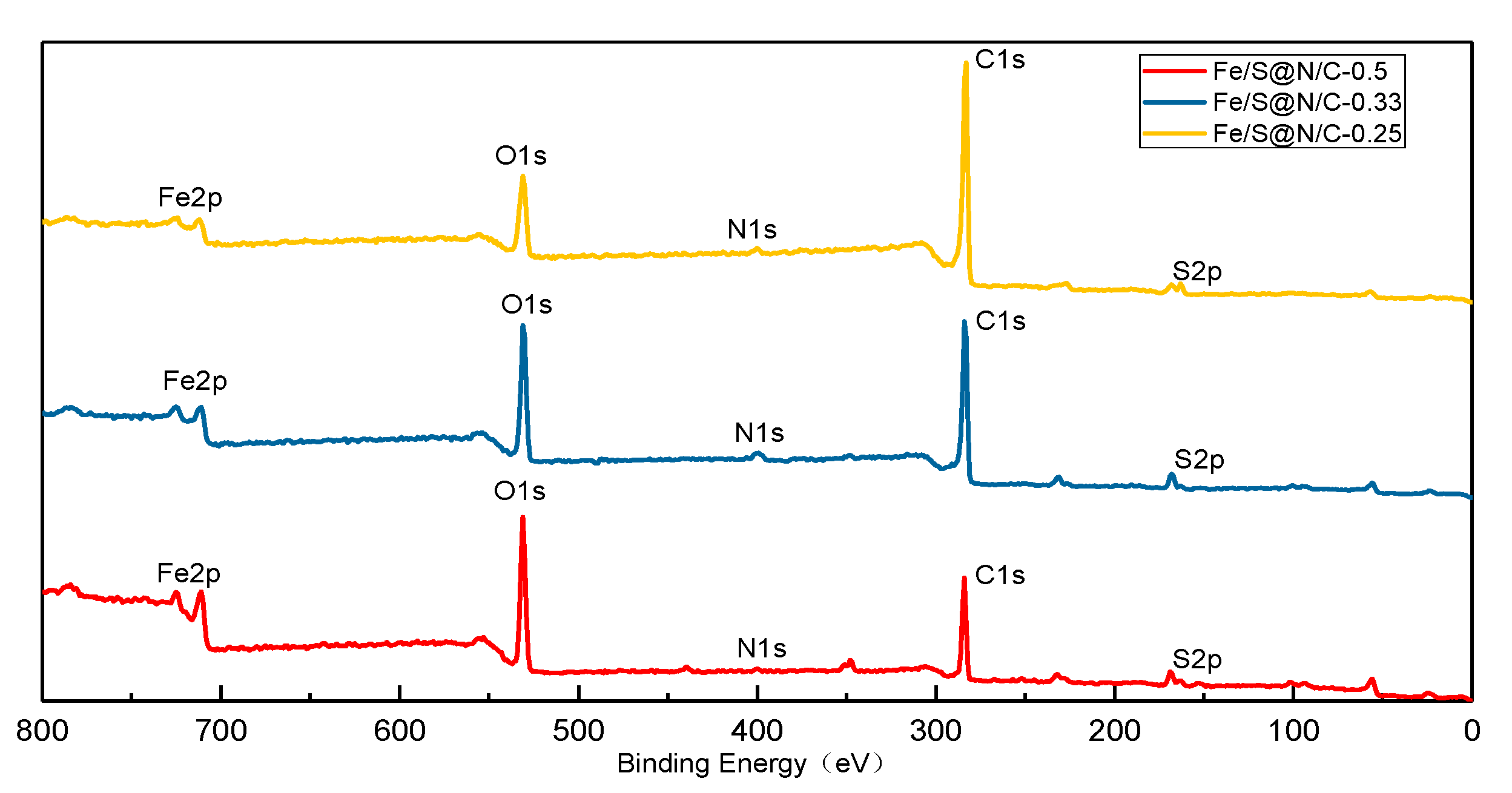
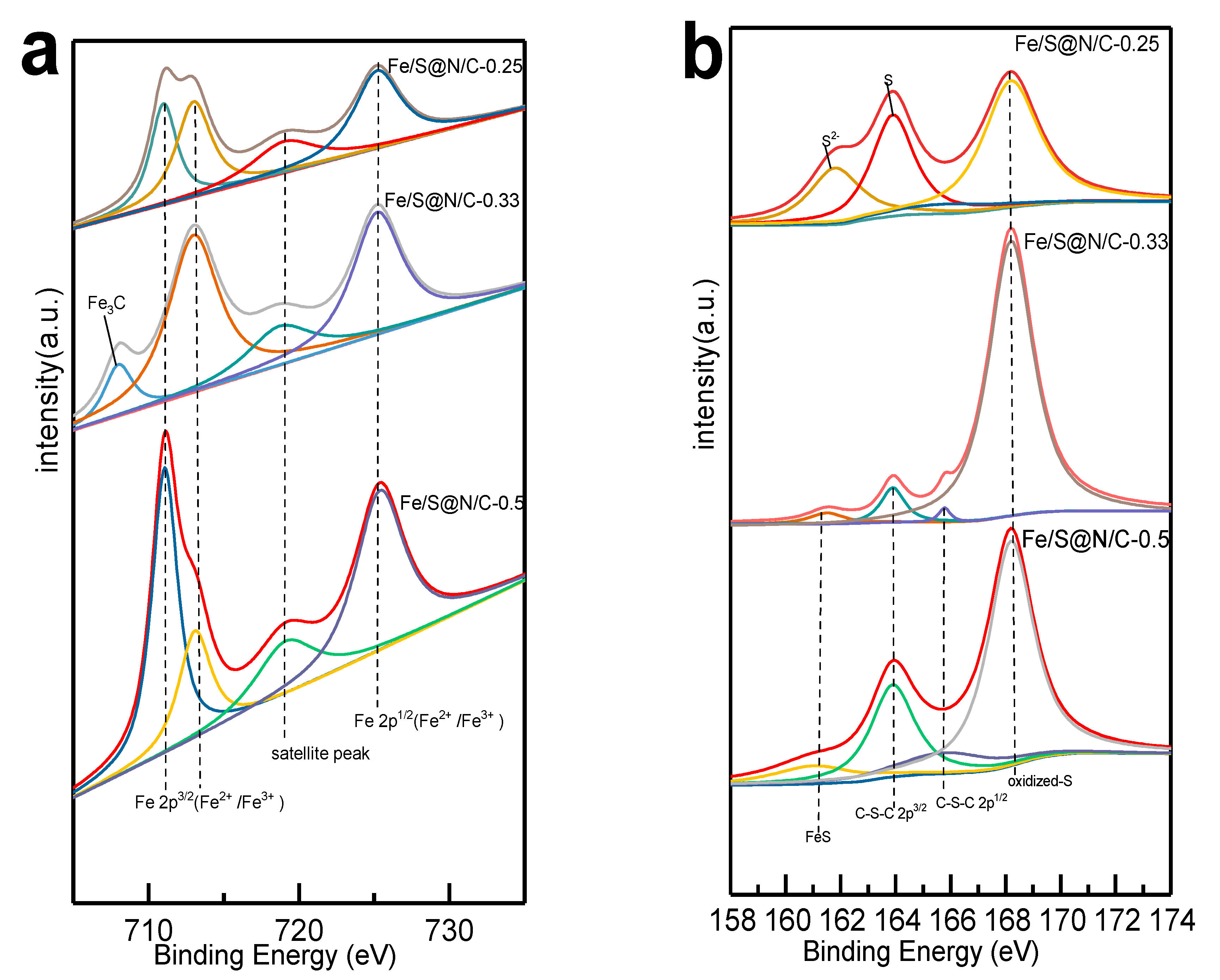
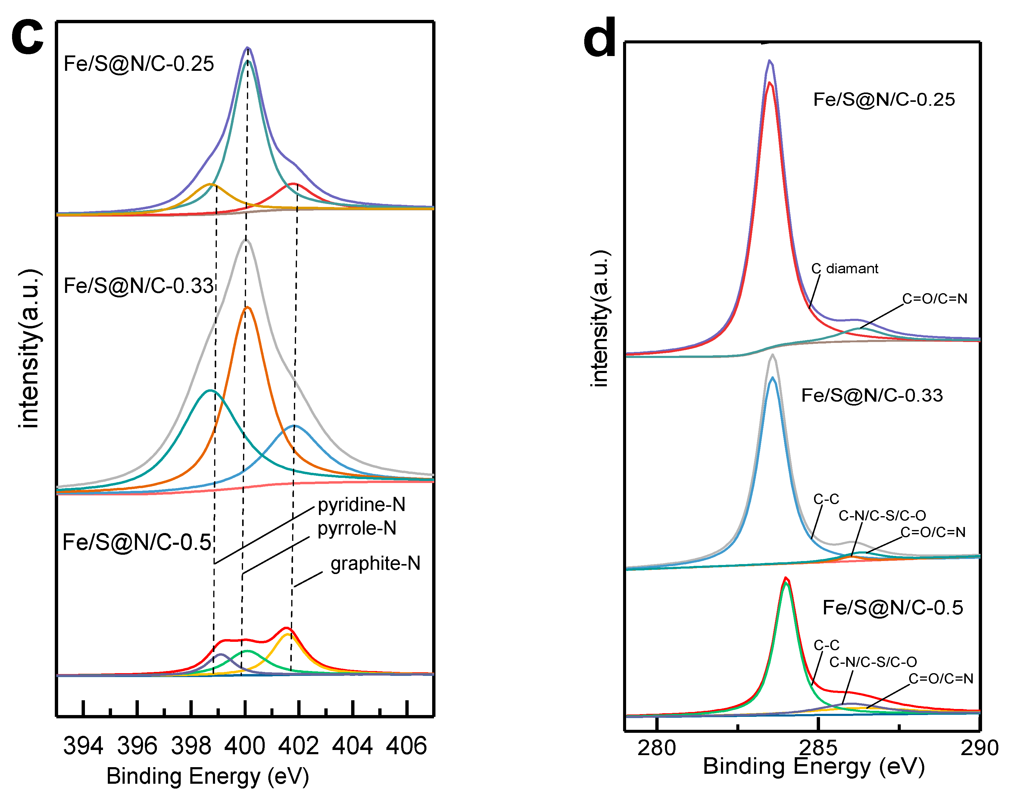
X-ray photoelectron spectroscopy (XPS) was employed to clarify the detailed chemical profiles for all sorts of elements in Fe/S@N/C-x, and the data were plotted in Figure 7 and Figure 8. Survey spectra in Figure 7 confirm the existence of Fe, O, N, C, and S elements in all Fe/S@N/C-x samples. The photoelectric peaks of the N 1s spectrum imply the presences of pyridinic N, pyrrolic N, and graphitic N [52] with a binding energy center at 398.6, 400.1, and 401.8 eV, respectively (Figure 8c supporting information). In Figure 8b, the S2p spectra of Fe/S@N/C-0.5 and Fe/S@N/C-0.33 samples’ main crystal phases of FeS could both match well with the C-S-C chemical bonding; the peaks at 163.8 eV and 165.7 eV correspond to S 2p3/2 and S 2p1/2, respectively. The appearance of C-S-C bond confirms that S atoms were successfully incorporated into the structure of aromatic carbon, the active site of which is believed to be thiophene S [53]. The binding energy of 161 eV is related to FeS, and another peak at 168.2eV corresponds to SOx. The deconvoluted Fe 2p spectra in Figure 8a show the formation of Fe 2p3/2 (Fe2+/Fe3+) and 2p1/2 (Fe2+/Fe3+) in all Fe/S@N/C-x samples at approximately 711–713 and 716.5 eV, respectively. The powerful interaction between Fe2+ and S species could give rise to the production of FeS [54,55]. It is widely reported that these nanoparticles could be the active sites for ORR performance [56]. For Fe/S@N/C-0.33, an extra weaker peak at 708.4 eV emerges, which is matched with Fe/Fe3C. For the last few years, many studies have shown that the catalytic activity could be significantly diminished when Fe3C exists [57], and the same is true for aggregate Fe particles. Hence, the Fe/S@N/C-0.33 catalyst displays a weaker ORR performance compared with Fe/S@N/C-0.5, even though their main phases are the same (FeS). As for the C 1s spectrum of the Fe/S@N/C-0.5 and Fe/S@N/C-0.33 samples, the binding energy values of 284, 286, and 286.3 eV are relevant to C-C, C-N/C-S/C-O and C = O/C = N, respectively (Figure 8d). Additionally, as shown in the table of the proportion for each element (Table 4), the atomic contents of S and Fe are proportional in Fe/S@N/C-0.5, and both are the highest among the three samples. Within a certain concentration range, the ORR activity increased with the increase of the Fe content, and similar conclusions have been reached in some previous research [58]. Corresponding to the electrochemical properties tested above, it can be clearly seen that the content of S also has a positive correlation with the ORR activity. That is, Fe/S@N/C-0.5 (S% = 6.63) > Fe/S@N/C-0.5 (S% = 4.32) > Fe/S@N/C-0.5 (S% = 3.97), and the sum of the contents of Fe, N, and S follows this order as well.
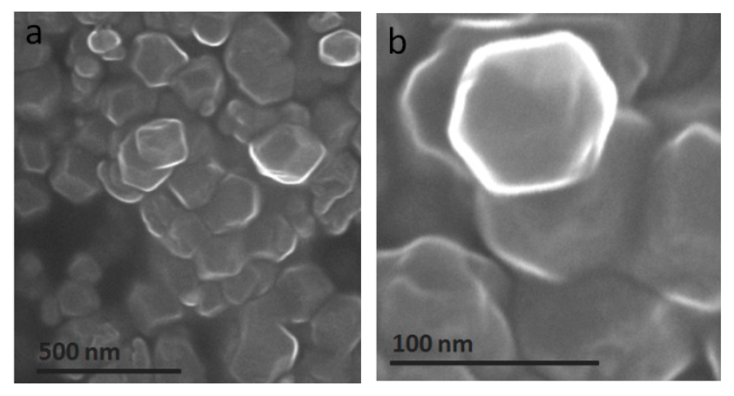
Scanning electron microscopy (SEM), transmission electron microscopy (TEM), and elemental maps of Fe, S, C, and N were employed to probe the structure and morphology of the Fe/S@N/C-0.5 catalyst. As shown in Figure 9a–c, the classical octahedral structure of ZIF-8 [59] remained in Fe-ZIF-8 and Fe/S@N/C-0.5 materials with a uniform size of ~80 nm, confirming that carbonization at a high temperature and modification processes such as S doping and acid etching could not destroy the original structure of the MOF. According to the SEM images, the surface morphology of the Fe/S@N/C-0.5 catalyst became rough compared with Fe-ZIF-8. No crystalline iron species and aggregated sulfur atoms are found in the TEM image (Figure 9d). Besides, based on the elemental mapping images of Fe/S@N/C-0.5 (Figure 9e), it is clear that Fe, N, S, and C are successfully dispersed uniformly in the material. These analyses correspond to the atomic-level dispersion of Fe, S, and N in Fe/S@N/C-0.5 materials and could promote the ORR activity [60,61].
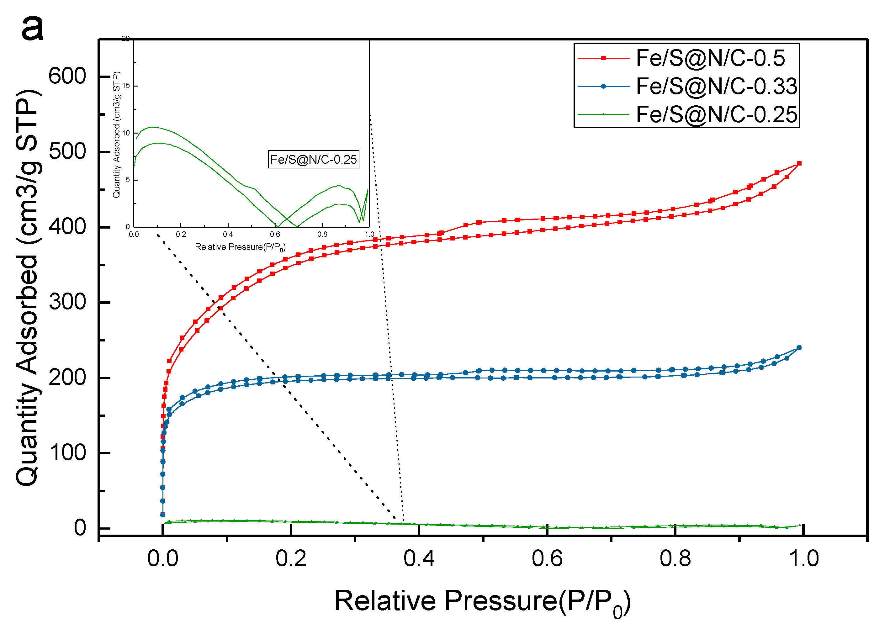
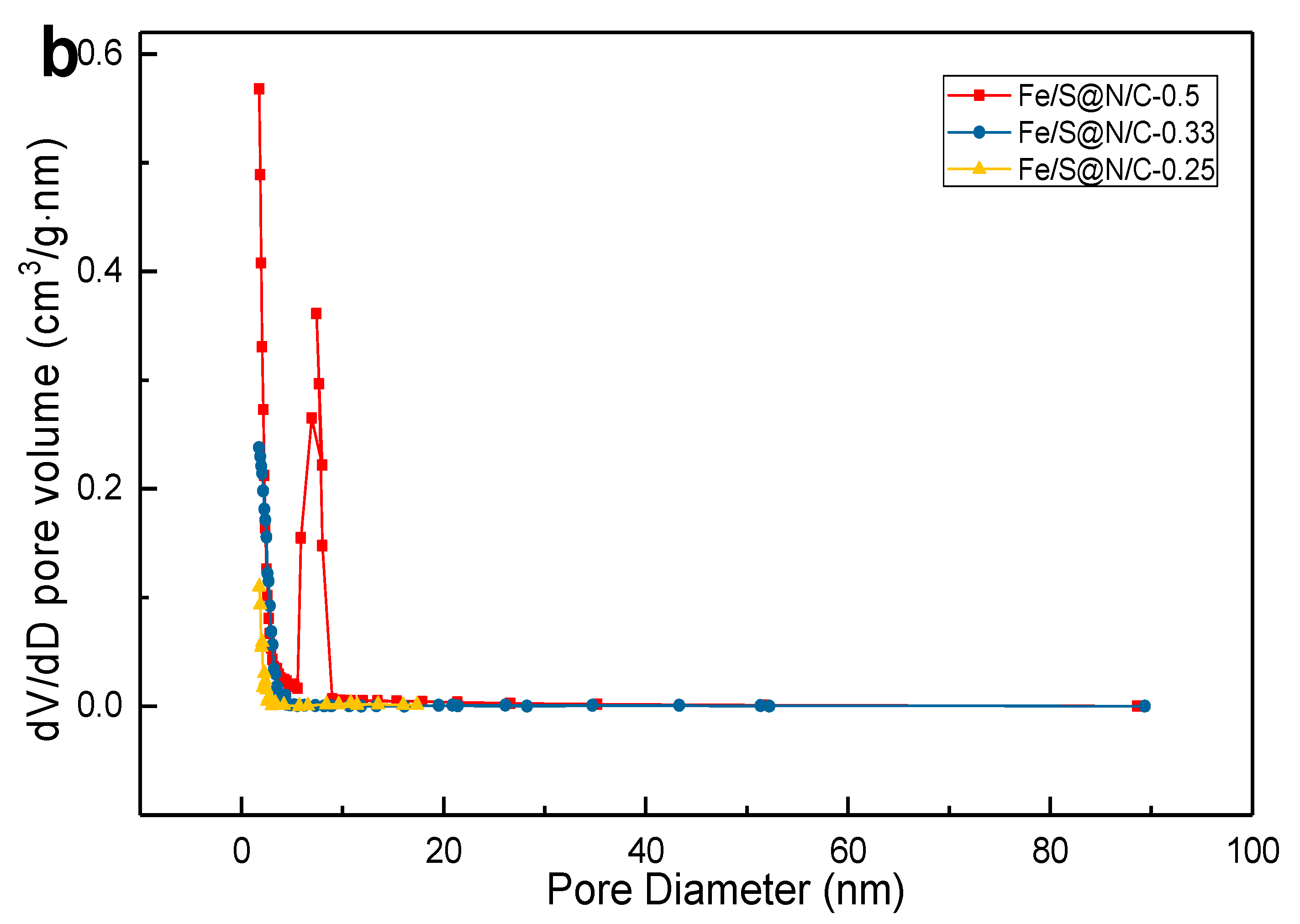
According to the N2 adsorption/desorption measurements at –196 °C, Fe/S@N/C-0.5 is quite different from the other two Fe/S@N/C-x (0.33, 0.25) in terms of the surface pore characteristics. Table 5 shows the details. The BET and Langmuir surface areas of the Fe/S@N/C-0.5 catalyst are 598 m2/g and 704 m2/g respectively; both of them are highest compared with the other two Fe/S@N/C-x (0.33, 0.25). As the graph (Figure 10a) shows, the N2 sorption isotherms of Fe/S@N/C-0.5 material contain the characteristics of typical type I and type IV isotherms [62], which shows a sharp increase in the low relative pressure and an obvious hysteresis loop in higher relative pressure, illustrating that mesopores (2–50 nm in diameter) and microporous (less than 2 nanometers in diameter) structures are present. By using the t-plot method and the Barrett–Joyner–Halenda (BJH) model, the pore size distribution curves were generated (Figure 10b supporting information) and further illustrate that the Fe/S@N/C-0.5 material contains a mass of micropores and mesopores. As seen in Table 5, it is clear that the pore diameters of the Fe/S@N/C-0.5 material are mainly distributed around 1.8 nm (micropores) and 7.5 nm (mesopores). Unlike the Fe/S@N/C-0.5, the Fe/S@N/C-0.33 and Fe/S@N/C-0.25 contain only micropores the diameters of which are 1.8 nm.
The content of iron has a remarkable effect on the pore structure. When the x value changes, the stability of the material structure is different, probably originating from the instability of the different building units derived from the different coordination numbers and geometries. Hence, based on this, the pristine MOF with a different stability may generate a structural rearrangement process during carbonization, where the leaving of O and H makes the original framework shrink and the gaseous products create the formation of gas tunnels. Another reason could be that the Fe/S@N/C-x (x = 0.5) sample contains the highest iron content, and the corresponding unstable Fe species are due to the higher amounts, thus, resulting in the formation of more mesopores. In general, the pore structure of the catalyst plays an important role in the ORR for MFCs as mesoscale pores benefit the diffusion of larger molecules with low resistance, while the microscale pores can provide effective catalytic sites of small molecules [63]. Thus, compared with the other two Fe/S@N/C-x (0.33, 0.25) catalysts, the richness of the pores and the larger specific surface in the Fe/S@N/C-0.5 material contribute to the enhanced ORR activity of the MFC [64].

4. Conclusions

We announce a facile strategy to synthesize the Fe/S@N/C-0.5 composite derived from ZIF-8 with FeS as the main phase. The Fe/S@N/C-0.5 catalyst shows pronounced ORR activity and high reduction kinetics, in which the ORR is predominantly a four-electron pathway with longer-term durability and excellent methanol tolerance. In alkaline media, the Fe/S@N/C-0.5 catalyst showed a half-wave potential (E1/2) of 0.87 V and a stronger diffusion-limiting current density (JL) of 6.16 mA·cm−1. In neutral PBS media, the Fe/S@N/C-0.5 catalyst showed a remarkable reduction potential at −0.03 V (vs. SCE). When being employed as a cathode catalyst in an single-chamber microbial fuel cell (MFC) of the air cathode, the prepared Fe/S@N/C-0.5 catalyst could outperform the commercial 20% Pt-C catalyst as far as the most important performance indicators of MFC are concerned. The Fe/S@N/C-0.5-MFC had a high OCV of 0.71 V and large maximum power density of 1196 mW/m2, both of which are beyond Pt/C-MFC under the same conditions. Furthermore, it had a more stable and higher output voltage during its operation compared with Pt/C-MFC. These results demonstrate that the Fe, N, and S co-doped Fe/S@N/C-0.5 is a robust catalyst for the oxygen reduction reaction in microbial fuel cells.

Author Contributions

Conceptualization, X.L.; Data curation, W.H., H.R. and Q.Z.; Formal analysis, W.H., H.R. and Q.Z.; Funding acquisition, X.L.; Investigation, X.L.; Methodology, W.H., H.R. and Q.Z.; Software, W.H., H.R. and Q.Z.; Writing—original draft, X.L. and W.H.; Writing—review & editing, X.L.

Funding

This research was funded by Open Project Program of State Key Laboratory of Petroleum Pollution Control, CNPC Research Institute of Safety and Environmental Technology (PPC2017002), and The APC was funded by Open Project Program of State Key Laboratory of Petroleum Pollution Control, CNPC Research Institute of Safety and Environmental Technology.

Conflicts of Interest

The authors declare no conflict of interest.

References

  1. Guo, S.J.; Zhang, S.; Sun, S.S. Tuning Nanoparticle Catalysis for the Oxygen Reduction Reaction. Angew. Chem. Int. Ed. 2013, 52, 8526–8544. [Google Scholar] [CrossRef] [PubMed]
  2. Jaouen, F.; Proietti, E.; Lefèvre, M.; Chenitz, R.; Dodelet, J.-P.; Wu, G.; Chung, H.T.; Johnstonb, C.M.; Zelenay, P. Recent advances in non-precious metal catalysis for oxygen-reduction reaction in polymer electrolyte fuel cells. Energy Environ. Sci. 2011, 4, 114–130. [Google Scholar] [CrossRef]
  3. Hara, M.; Kitano, M.; Hosono, H. Ru-loaded C12A7: E’ electride as a catalyst for ammonia synthesis. ACS Catal. 2017, 7, 2313–2324. [Google Scholar] [CrossRef]
  4. Kitano, M.; Kanbara, S.; Inoue, Y.; Kuganathan, N.; Sushko, P.V.; Yokoyama, T.; Hara, M.; Hosono, H. Electride support boosts nitrogen dissociation over ruthenium catalyst and shifts the bottleneck in ammoia synthesis. Nat. Commun. 2015, 6, 6731. [Google Scholar] [CrossRef] [PubMed]
  5. Zhu, C.Z.; Dong, S.J. Recent progress in graphene-based nanomaterials as advanced electrocatalysts towards oxygen reduction reaction. Nanoscale 2013, 5, 1753–1767. [Google Scholar] [CrossRef]
  6. Zhang, C.; Mahmood, N.; Yin, H.; Liu, F.; Hou, Y. Synthesis of Phosphorus-Doped Graphene and its Multifunctional Applications for Oxygen Reduction Reaction and Lithium Ion Batteries. Adv. Mater. 2013, 25, 4932–4937. [Google Scholar] [CrossRef]
  7. Liang, J.; Zheng, Y.; Chen, J.; Liu, J.; Hulicova-Jurcakova, D.; Jaroniec, M.; Qiao, S.Z. Facile Oxygen Reduction on a Three-Dimensionally Ordered Macroporous Graphitic C3N4/Carbon Composite Electrocatalyst. Angew. Chem. Int. Ed. 2012, 51, 3892–3896. [Google Scholar] [CrossRef]
  8. Lefevre, M.; Proietti, E.; Jaouen, F.; Dodelet, J.-P. Iron-Based Catalysts with Improved Oxygen Reduction Activity in Polymer Electrolyte Fuel Cells. Science 2009, 324, 71–74. [Google Scholar] [CrossRef]
  9. Yun, J.; Smith, V.H.; Pate, R.C. Managing nutrients and system operations for biofuel production from freshwater macroalgae. Algal Res. 2015, 11, 13–21. [Google Scholar] [CrossRef]
  10. Quek, S.B.; Cheng, L.; Cord-Ruwisch, R. Microbial fuel cell biosensor for rapid assessment of assimilable organic carbon under marine conditions. Water Res. 2015, 77, 64–71. [Google Scholar] [CrossRef] [Green Version]
  11. Liew, K.B.; Daud, W.R.W.; Ghasemi, M. Non-Pt catalyst as oxygen reduction reaction in microbial fuel cells: A review. Int. J. Hydrog. Energy 2014, 39, 4870–4883. [Google Scholar]
  12. Aspear, S.; Kawai, H. Density functional theory-based analysis on O2 molecular interaction with the tri-s-triazine-based graphitic carbon nitride. Surf. Sci. 2012, 606, 892–901. [Google Scholar] [CrossRef]
  13. Zhu, C.Z.; Fu, S.F.; Song, J.H.; Shi, Q.R.; Su, D.; Mark, H.; Engelhard, X.L. Self-Assembled Fe-N-Doped Carbon Nanotube Aerogels with Single-Atom Catalyst Feature as High-Efficiency Oxygen Reduction Electrocatalysts. Small 2017, 13, 1603407. [Google Scholar] [CrossRef] [PubMed]
  14. Yang, Z.; Zhao, Z.; Liang, K.; Zhou, X.; Shen, C.; Liu, Y.; Wang, X.; Xu, A. Synthesis of nanoporous structured iron carbide/Fe–N–carbon composites for efficient oxygen reduction reaction in Zn–air batteries. J. Mater. Chem. A 2016, 4, 19037–19044. [Google Scholar] [CrossRef]
  15. Deng, D.H.; Yu, L.; Chen, X.Q.; Wang, G.X.; Jin, L.; Pan, X.L.; Deng, J.; Sun, G.Q.; Bao, X.H. Iron Encapsulated within Pod-like Carbon Nanotubes for Oxygen Reduction Reaction. Angew. Chem. 2013, 52, 371–375. [Google Scholar] [CrossRef] [PubMed]
  16. Sun, Z.; An, L.; Jiang, N.; Li, B.; Hua, S.; Fu, Y.; Liu, J.; Hao, W.; Xia, D. A highly active and durable iron/cobalt alloy catalyst encapsulated in N-doped graphitic carbon nano. J. Mater. Chem. A 2018, 6, 5962–5970. [Google Scholar]
  17. Bracamonte, V.; Melchionna, M.; Stopin, A.; Giulani, A. Carboxylated, Fe-Filled Multiwalled Carbon Nanotubes as Versatile Catalysts for O2− Reduction and H2− Evolution Reactions at Physiological pH. Chem. Eur. J. 2015, 21, 12769–12777. [Google Scholar] [CrossRef]
  18. Li, J.Z.; Chen, M.J.; David, A.; Wang, M.Y. Atomically dispersed manganese catalysts for oxygen reduction in proton-exchange membrane fuel cells. Nat. Catal. 2018, 1, 935–945. [Google Scholar] [CrossRef]
  19. Anna, L.; Manuela, B.; Claudio, T.; Lucia, N. Selective Electrocatalytic H2O2 Generation by Cobalt@N-Doped Graphitic Carbon Core–Shell Nanohybrids. ChemSusChem 2019, 12, 1664–1672. [Google Scholar]
  20. Wang, Q.; Zhou, Z.Y.; Lai, Y.J.; You, Y.; Liu, J.G.; Wu, X.L.; Terefe, E.; Chen, C.; Song, L.; Rauf, M.; et al. Phenylenediamine-Based FeNx/C Catalyst with High Activity for Oxygen Reduction in Acid Medium and Its Active-Site Probing. Am. Chem. Soc. 2014, 136, 10882–10885. [Google Scholar] [CrossRef]
  21. Chung, H.T.; Cullen, D.A.; Higgins, D. Direct atomic-level insight into the active sites of a high-performance PGM-free ORR catalyst. Science 2017, 357, 479–484. [Google Scholar] [CrossRef] [PubMed] [Green Version]
  22. Perez-Alonso, F.J.; Dominguez, C.; Al-Thabaiti, S.A. Evidences of the presence of different types of active sites for the oxygen reduction reaction with Fe/N/C based catalysts. J. Power Sources 2016, 327, 204–211. [Google Scholar] [CrossRef]
  23. Ingale, P.; Sakthivel, M.; Drillet, J.F. Test of Diethylmethylammonium Trifluoromethanesulfonate Ionic Liquid as Electrolyte in Electrically Rechargeable Zn/Air Battery. J. Electrochem. Soc. 2017, 164, H5224–H5229. [Google Scholar] [CrossRef]
  24. Zhang, J.; Xu, D.; Wang, C.; Guo, J.; Yan, F. Rational Design of Fe1–xS/Fe3O4/Nitrogen and Sulfur Doped Porous Carbon with Enhanced Oxygen Reduction Reaction Catalytic Activity. Adv. Mater. Interfaces 2018. [Google Scholar] [CrossRef]
  25. Liu, B.H.; Li, Z.P. Current status and progress of direct borohydride fuel cell technology development. J. Power Sources 2009, 187, 291–297. [Google Scholar] [CrossRef]
  26. Gorlin, Y.; Lassalle-Kaiser, B.; Benck, J.D.; Gul, S.; Webb, S.M.; Yachandra, V.K.; Yano, J.; Jaramillo, T.F. In-Situ X-Ray Absorption Spectroscopy Investigation of a Bifunctional Manganese Oxide Catalyst with High Activity for Electrochemical Water Oxidation and Oxygen Reduction. J. Am. Chem. Soc. 2013, 135, 8525–8534. [Google Scholar] [CrossRef] [PubMed]
  27. Pampel, J.; Fellinger, T.-P. Opening of Bottleneck Pores for the Improvement of Nitrogen Doped Carbon Electrocatalysts. Adv. Energy Mater. 2016, 6, 1502389. [Google Scholar] [CrossRef]
  28. Schaber, P.; Colson, J.; Higgins, S.; Thieln, D.; Anspach, B.; Brauer, J. Thermal de-composition (pyrolysis) of urea in an open reaction vessel. Thermochim. Acta 2004, 424, 131–142. [Google Scholar] [CrossRef]
  29. Olszowska, K.; Pang, J.; Wrobel, P.S.; Zhao, L.; Ta, H.Q.; Liu, Z.; Trzebicka, B.; Bachmatiuk, A.; Rummeli, M.H. Three-dimensional nanostructured graphene: Synthesis and energy, environmental and biomedical applications. Synth. Met. 2017, 234, 53–85. [Google Scholar] [CrossRef]
  30. Fei, H.L.; Yang, Y.; Fan, X.J.; Wang, G.; Ruan, G.D.; Tour, J.M. Tungsten-Based Porous Thin-Films for Electrocatalytic Hydrogen Generation—Electronic Supplementary Information. J. Mater. Chem. A 2015, 3, 5798–5804. [Google Scholar] [CrossRef]
  31. Stoerzinger, K.A.; Hong, W.T.; Azimi, G.; Giordano, L.; Lee, Y.-L.; Crumlin, E.J.; Biegalski, M.D.; Bluhm, H.; Varanasi, K.K.; Shao-Horn, Y. Reactivity of Perovskites with Water: Role of Hydroxylation in Wetting and Implications for Oxygen Electrocatalysis. J. Phys. Chem. C 2015, 119, 18504–18512. [Google Scholar] [CrossRef] [Green Version]
  32. Liu, S.; Yang, Z.; Li, M.; Liu, L.; Wang, Y.; Lv, W.; Qin, Z.; Zhao, X.; Zhu, P.; Wang, G. FeS-decorated hierarchical porous N, S-dual-doped carbon derived from silica-ionogel as an efficient catalyst for oxygen reduction reaction in alkaline media. Electrhochim. Acta 2018, 265, 221–231. [Google Scholar] [CrossRef]
  33. Ma, X.X.; Su, Y.; He, X. Fe9S10-decorated N, S co-doped graphene as a new and efficient electrocatalyst for oxygen reduction and oxygen evolution reactions. Catal. Sci. Technol. 2017, 7, 1181–1192. [Google Scholar] [CrossRef]
  34. Lalande, G.; Côté, R.; Tamizhmani, G.; Guay, D.; Dodelet, J.P.; Dignard-Bailey, L.; Weng, L.T.; Bertrand, P. Physical, chemical and electrochemical characterization of heat-treated tetracarboxylic cobalt phthalocyanine adsorbed on carbon black as electrocatalyst for oxygen reduction in polymer electrolyte fuel cells. Electrochim. Acta 1995, 40, 2635–2646. [Google Scholar] [CrossRef]
  35. Morris, J.M.; Jin, S.; Wang, J.; Zhu, C.; Urynowicz, M.A. Lead dioxide as an alternative catalyst to platinum in microbial fuel cells. Electrochem. Commun. 2007, 9, 1730–1734. [Google Scholar] [CrossRef]
  36. Valipour, A.; Ayyaru, S.; Ahn, Y. Application of graphene-based nanomaterials as novel cathode catalysts for improving power generation in single chamber microbial fuel cells. J. Power Sources 2016, 327, 548–556. [Google Scholar] [CrossRef]
  37. Santoro, C.; Serov, A.; Narvaez Villarrubia, C.W.; Stariha, S.; Babanova, S.; Schuler, A.J.; Artyushk, K.; Atanassov, P. Double-chamber microbial fuel cell with a non-platinum-group metal Fe–N–C cathode catalyst. ChemSusChem 2015, 8, 828–834. [Google Scholar] [CrossRef]
  38. Feng, L.; Yan, Y.; Chen, Y.; Wang, L. Nitrogen-Doped Carbon Nanotubes as Efficient and Durable Metal-Free Cathodic Catalysts for Oxygen Reduction in Microbial Fuel Cells. Energy Environ. Sci. 2011, 4, 1892–1899. [Google Scholar] [CrossRef]
  39. Santoro, C.; Li, B.; Cristiani, P.; Squadrito, G. Power generation of microbial fuel cells (MFCs) with low cathodic platinum loading. Int. J. Hydrog. Energy 2013, 38, 692–700. [Google Scholar] [CrossRef]
  40. Kannan, M.V.; Kumar, G.G. Current status, key challenges and its solutions in the design and development of graphene based ORR catalysts for the microbial fuel cell applications. Biosens. Bioelectron. 2016, 77, 1208–1220. [Google Scholar] [CrossRef]
  41. Rabaey, K.; Verstraete, W. Microbial fuel cells: Novel biotechnology for energy generation. Trends Biotechnol. 2005, 23, 291–298. [Google Scholar] [CrossRef] [PubMed]
  42. Sun, L.; Tian, C.; Fu, Y.; Yang, Y.; Yin, J.; Wang, L.; Fu, H. Nitrogen-doped porous graphitic carbon as an excellent electrode material for advanced supercapacitors. Chem. A Eur. J. 2014, 20, 564–574. [Google Scholar] [CrossRef] [PubMed]
  43. Bi, L.; Ci, S.; Cai, P.; Li, H.; Wen, Z. One-step pyrolysis route to three dimensional nitrogen-doped porous carbon as anode materials for microbial fuel cells. Appl. Surf. Sci. 2018, 427, 10–16. [Google Scholar] [CrossRef]
  44. Cheng, H.; Scott, K. Investigation of non-platinum cathode catalysts for direct borohydride fuel cells. J. Electroanal. Chem. 2006, 596, 117–123. [Google Scholar] [CrossRef]
  45. Cheng, S.; Liu, H.; Logan, B.E. Increased performance of single-chamber microbial fuel cells using an improved cathode structure. Electrochem. Commun. 2006, 8, 489–494. [Google Scholar] [CrossRef]
  46. Santoro, C.; Serov, A.; Villarrubia, C.W.N.; Stariha, S.; Babanova, S.; Artyushkova, K.; Schuler, A.J.; Atanassov, P. High catalytic activity and pollutantsresistivity using Fe-AAPyr cathode catalyst for microbial fuel cell application. Sci. Rep. 2015, 5, 16596. [Google Scholar] [CrossRef] [PubMed]
  47. Jiang, T.; Wang, Y.; Wang, K.; Liang, Y.; Wu, D.; Tsiakaras, P.; Song, S. A novel sulfur-nitrogen dual doped ordered mesoporous carbon electrocatalyst for efficient oxygen reduction reaction. Appl. Catal. B Environ. 2016, 189, 11. [Google Scholar] [CrossRef]
  48. Bayram, E.; Yilmaz, G.; Mukerjee, S. A solution-based procedure for synthesis of nitrogen doped graphene as an efficient electrocatalyst for oxygen reduction reactions in acidic and alkaline electrolytes. Appl. Catal. B Environ. 2016, 192, 26–34. [Google Scholar] [CrossRef]
  49. Guerrini, E.; Grattieri, M.; Faggianelli, A.; Cristiani, P.; Trasatti, S. PTFE effect on the electrocatalysis of the oxygen reduction reaction in membraneless microbial fuel cells. Bioelectrochemistry 2015, 106, 240–247. [Google Scholar] [CrossRef] [PubMed]
  50. Watson, V.J.; Delgado, C.N.; Logan, B.E. Influence of Chemical and Physical Properties of Activated Carbon Powders on Oxygen Reduction and Microbial Fuel Cell Performance. Environ. Sci. Technol. 2013, 47, 6704–6710. [Google Scholar] [CrossRef] [PubMed]
  51. Freguia, S.; The, E.H.; Boon, N.; Leung, K.M.; Keller, J.; Rabaey, K. Microbial fuel cells operating on mixed fatty acids. Bioresour. Technol. 2010, 101, 1233–1238. [Google Scholar] [CrossRef] [PubMed]
  52. Subbaraman, R.; Tripkovic, D.; Chancg, K.C.; Strmcnik, D.; Paulikas, A.P.; Hirunsit, P.; Chan, M.; Greeley, J.; Stamenkovic, V.; Markovic, N.M. Trends in activity for the water electrolyser reactions on 3d M(Ni,Co,Fe,Mn) hydr(oxy)oxide catalyst. Nat. Mater. 2012, 11, 550–557. [Google Scholar] [CrossRef] [PubMed]
  53. Malik, D.J.; Trochimczuk, A.W.; Jyo, A.; Tylus, W. Synthesis and Characterization of nanostructured carbons with controlled porosity prepared from sulfonated divinylbiphenyl copolymers. Carbon 2008, 46, 310–319. [Google Scholar] [CrossRef]
  54. Li, Q.; Chen, W.; Xiao, H.; Gong, Y.; Li, Z.; Zheng, L.; Yan, W.; Cheong, W.; Shen, R.; Fu, N.; et al. Fe Isolated Single Atoms on S, N Codoped Carbon by Copolymer Pyrolysis Strategy for Highly Efficient Oxygen Reduction Reaction. Adv. Master. 2018, 30, 1800588. [Google Scholar] [CrossRef] [PubMed]
  55. Men, B.; Sun, Y.; Liu, J.; Tang, Y.; Chen, Y.; Wan, P.; Pan, J. Synergistically Enhanced Electrocatalytic Activity of Sandwich-like N-Doped Graphene/Carbon Nanosheets Decorated by Fe and S for Oxygen Reduction Reaction. ACS Appl. Master. Interfaces 2016, 30, 19533–19541. [Google Scholar] [CrossRef] [PubMed]
  56. Li, Q.; Wu, G.; Cullen, D.A.; More, K.L.; Mack, N.H.; Chung, H.T.; Zelenay, P. Phosphate-Tolerant Oxygen Reduction Catalysts. ACS Catal. 2014, 4, 3193–3200. [Google Scholar] [CrossRef] [Green Version]
  57. Zitolo, A.; Goellner, V.; Armel, V.; Sougrati, M.-T.; Mineva, T.; Stievano, L.; Fonda, E.; Jaouen, F. Identification of catalytic sites for oxygen reduction in iron- and nitrogen-doped graphene materials. Nat. Mater. 2015, 14, 937–942. [Google Scholar] [CrossRef] [PubMed]
  58. Nguyen, M.-T.; Mecheri, B.; Iannaci, A.; D’Epifanio, A.; Licoccia, S. Iron/polyindole-based electrocatalysts to enhance oxygen reduction in microbial fuel cells. Electrochim. Acta 2016, 190, 388–395. [Google Scholar] [CrossRef]
  59. Haolin, T.; Yan, Z.; Yin, Z.; Rui, W.; Shichang, C.; Cong, L.; Haopeng, C. Iron-embedded nitrogen doped carbon frameworks as robust catalyst for oxygen reduction reaction in microbial fuel cells. J. Power Sources 2014, 202, 550–556. [Google Scholar]
  60. Bruce, P.G.; Freunberger, S.A.; Hardwick, L.J.; Tarascon, J.M. Li-O2 and Li-S batteries with high energy storage. Nat. Mater. 2012, 11, 19–29. [Google Scholar] [CrossRef]
  61. Ferrandon, M.; Kropf, A.J.; Myers, D.J. Multitechnique Characterization of a Polyaniline–Iron–Carbon Oxygen Reduction Catalyst. J. Phys. Chem. C 2012, 116, 16001–16013. [Google Scholar] [CrossRef]
  62. Armel, V.; Hindocha, S.; Salles, F. Structural Descriptors of Zeolitic-Imidazolate Frameworks Are Keys to the Activity of Fe-N-C Catalysts. J. Am. Chem. Soc. 2017, 139, 453–464. [Google Scholar] [CrossRef] [PubMed]
  63. Jiang, W.J.; Gu, L.; Li, L. Understanding the High Activity of Fe–N–C Electrocatalysts in Oxygen Reduction: Fe/Fe3C Nanoparticles Boost the Activity of Fe–Nx. J. Am. Chem. Soc. 2016, 138, 3570–3578. [Google Scholar] [CrossRef] [PubMed]
  64. Kim, S.-W.; Seo, D.-H.; Ma, X.; Ceder, G.; Kang, K. Electrode Materials for rechargeable sodium-ion batteries: Potential alternatives to current lithium-ion batteries. Adv. Energy Mater. 2012, 2, 710–721. [Google Scholar] [CrossRef]
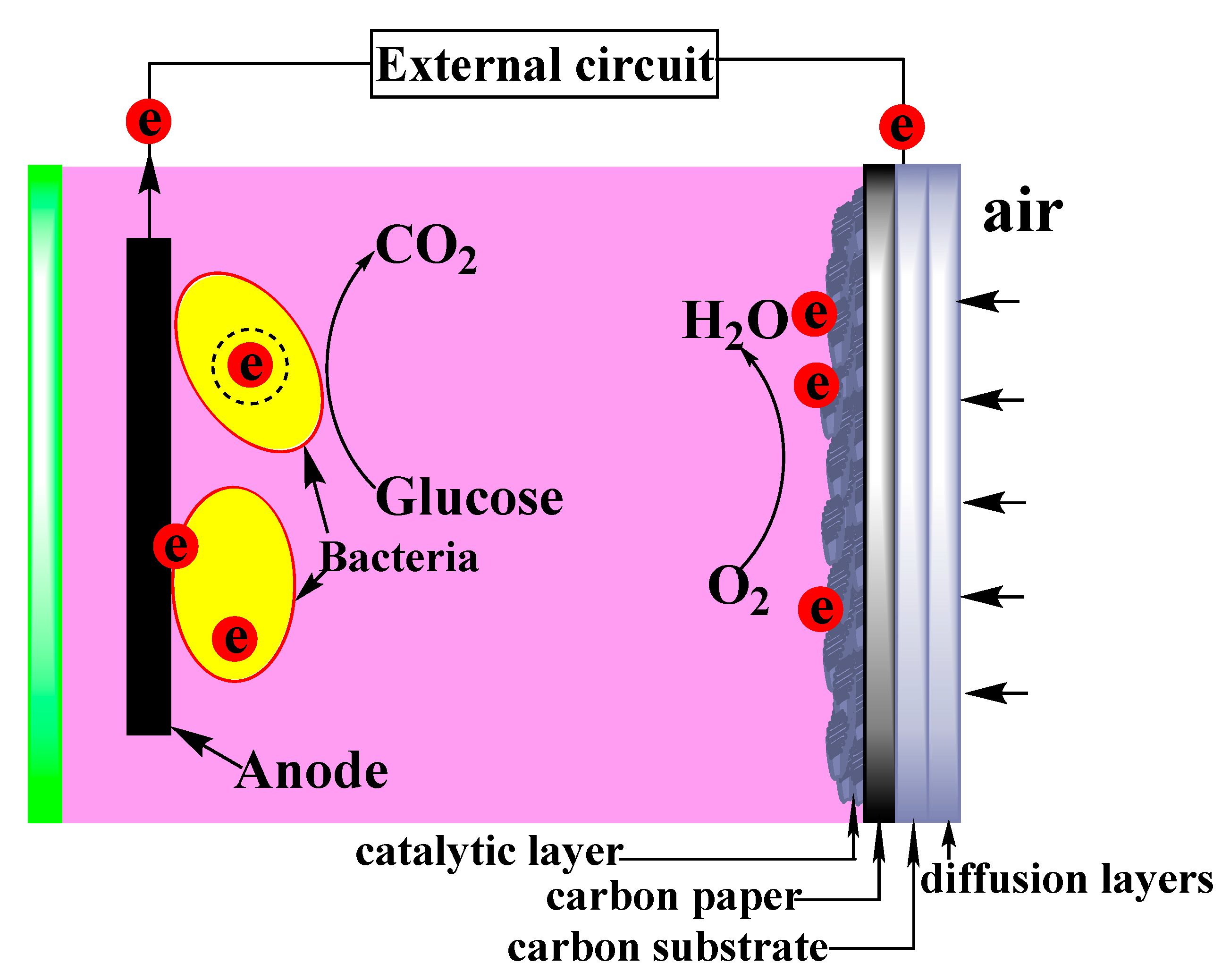
Figure 1. Schematic diagram of assembled microbial fuel cell (MFC) equipment with carbon felt anode and Fe/S@N/C-0.5 catalyst-loaded carbon paper cathode.
Energies 12 03846 g001
Figure 2. (a) The supernatant of oily sludge. (b,c) Culture medium containing the bacteria.
Energies 12 03846 g002
Figure 3. The oxygen reduction reaction (ORR) performance of Fe/S@N/C-x in 0.1 M KOH solution. (a) CV curves of Fe/S@N/C-x. (b) Linear sweep voltammogram (LSV) curves of Fe/S@N/C-x and 20% Pt/C in O2-saturated 0.1 M KOH solution at 1600 rpm with a scan rate of 5 mV/s. (c) LSV curves of Fe/S@N/C-0.5 with different rotating rates at a scan rate of 5 mV/s. (d) Koutecky–Levich (K-L) equation of Fe/S@N/C-0.5 with different potentials. (e,f) Stability curves and methanol tolerance curves for Fe/S@N/C-0.5 and 20% Pt/C catalysts in O2-saturated 0.1 M KOH at 1600 rpm.
Energies 12 03846 g003
Figure 4. (a) CV curves of Fe/S@N/C-0.5 and 20% Pt-C in O2 and N2-saturated 0.01 M PBS solution. (b) Linear sweep voltammogram (LSV) curves of Fe/S@N/C-0.5 and 20% Pt-C in O2-saturated 0.01 M PBS solution at 1600 rpm.
Energies 12 03846 g004
Figure 5. (a) Overall MFC polarization curves and power curves for the 20% Pt/C catalyst and Fe/S@N/C-0.5 catalyst. (b) Comparisons of output voltage in the operation of 20% Pt/C-MFC and Fe/S@N/C-0.5-MFC.
Energies 12 03846 g005
Figure 6. (a) XRD patterns of precursor of Fe/S@N/C-0.5. (b) XRD patterns of Fe/S@N/C-0.5 and Fe/S@N/C-0.33. (c) XRD patterns of Fe/S@N/C-0.25.
Energies 12 03846 g006
Figure 7. Survey XPS spectrum of Fe/S@N/C-x.
Energies 12 03846 g007
Figure 8. (a) High-resolution Fe 2p XPS spectrum of Fe/S@N/C-x. (b) High-resolution S2p N1s XPS spectrum of Fe/S@N/C-x. (c) High-resolution N1s XPS spectrum of Fe/S@N/C-x. (d) High-resolution C1s XPS spectrum of Fe/S@N/C-x.
Energies 12 03846 g008aEnergies 12 03846 g008b
Figure 9. (a,b) SEM images of Fe-ZIF-8. (c) SEM images of Fe/S@N/C-0.5. (d) TEM of Fe/S@N/C-0.5. (e) HAADF-STEM mapping of Fe/S@N/C-0.5.
Energies 12 03846 g009aEnergies 12 03846 g009b
Figure 10. (a) N2 adsorption/desorption isotherms of Fe/S@N/C-x. (b) Pore size distribution data obtained by the Barrett–Joyner–Halenda (BJH) method of Fe/S@N/C-x.
Energies 12 03846 g010aEnergies 12 03846 g010b
Table 1. Formulation of glucose solution.
ConstituentConcentration
glucose1 g/L
PBS (phosphate buffered saline)50 mmol/L
vitamin5 mL/L
minerals12.5 mL/L
Table 2. Formulation of vitamin solution.
VitaminConcentration (mg/L)VitaminConcentration (mg/L)
biotin2nicotinic acid5
folic acid2vitamin b120.1
pyridoxine hydrochloride10DL-calcium
pantothenate
5
thiamine
hydrochloride
5p-aminobenzoic acid5
riboflavin5lipoic acid5
Table 3. Formulation of trace mineral element solution.
MineralConcentration (mg/L)
NaCl sodium chloride1
CaCl2 calcium chloride0.08
MgSO4·7H2O magnesium sulfate heptahydrate6.14
MgSO4·H2O magnesium sulfate monohydrate0.56
ZnSO4·7H2O zinc sulfate heptahydrate0.27
FeSO4·7H2O ferrous sulfate heptahydrate0.1
CuSO4·5H2O copper pentahydrate sulfate0.01
Table 4. Proportion of each element for Fe/S@N/C-x.
SamplesC (%)N (%)S (%)Fe (%)
Fe/S@N/C-0.550.470.76.636.2
Fe/S@N/C-0.3364.723.594.323.87
Fe/S@N/C-0.2576.851.893.972.62
Table 5. BET and Langmuir surface area and pore diameter of Fe/S@N/C-x.
SamplesSBET (m2/g)SLangmuir (m2/g)Dmicropore (nm)Dmesopore (nm)
Fe/S@N/C-0.55987041.87.5
Fe/S@N/C-0.333675821.8——
Fe/S@N/C-0.252093111.8——