Article

Performance Analysis of Hydrofoil Shaped and Bi-Directional Diffusers for Cross Flow Tidal Turbines in Single and Double-Rotor Configurations

Department of Energy, Systems, Territory and Constructions Engineering, University of Pisa, l.go Lucio Lazzarino, 56122 Pisa, Italy
*
Author to whom correspondence should be addressed.
Energies 2019, 12(2), 272; https://doi.org/10.3390/en12020272
Submission received: 6 December 2018 / Revised: 8 January 2019 / Accepted: 11 January 2019 / Published: 16 January 2019
(This article belongs to the Section A: Sustainable Energy)

Abstract

:
With the aim of finding efficient solutions for cross flow turbine (CFT) bi-directional diffusers able to harvest non perfectly rectilinear tidal currents, a 2D CFD analysis of ducted CFTs was carried out with focus on the effects of diffuser shape and yaw angle. The HARVEST hydrofoil shaped diffuser, equipped with a pair of counter-rotating turbines, and a bi-directional symmetrical diffuser were compared in terms of coefficient of power (CP), torque ripple, overall thrust on diffuser and wake characteristics. Slightly better CP were predicted for the symmetrical diffuser, due to the convergent walls that address the flow towards the blade with a greater attack angle during early and late upwind and to the viscous interactions between the turbine wakes and strong vortices shed by the diffuser. A CP’s extraordinary improving resulted when yaw increased up to 22.5° for the hydrofoil shaped and up to 30° for the symmetrical diffuser. Similar behaviour in yawed flows also occurred in case of a ducted single rotor, demonstrating that it is a characteristic of CFTs. The insertion of a straight throat in the diffuser design proved to be an effective way to mitigate torque ripple, but a CP loss is expected.

1. Introduction

Offshore wind, tidal and waves energies are (in the order) economically and technically feasible ways of producing renewable energy and meet our sustainability targets. Tidal currents energy is characterised by predictability and low visual impact of the energy converters, and is considered one of the most favourable renewable resources in Europe. Horizontal axis or cross flow turbines (CFTs), also known as vertical axis turbines, can be employed. The main reasons for choosing a CFT are construction simplicity, low cost and the ability to work independently of flow direction. Floating platforms provide additional advantages: the generator and gearbox are set above the sea level, and higher currents can be harvested. Furthermore, the platform motion would negligibly affect power output, as CFTs exhibit good performance in skewed flow [1,2,3]. On the other hand, CFTs suffer of low starting-torque and lower efficiency respect to horizontal axis turbines, thus it is of great interest to find technologies to increase the production of a turbine having a certain cross-sectional area.
The cheapest way to increase the energy production is placing pairs of counter-rotating CFTs in close proximity, as proved by the experimental texts documented in [4,5,6]. A much more efficient solution to improve the power extraction of tidal, river or small wind generators is the diffuser, namely a device capable of increasing the local flow velocity at the turbine location. The effectiveness of diffuser augmented turbines has been investigated by several reputed authors [7,8,9,10,11,12], but its technical and economic feasibility is still debatable [13]. So far most of the studies in the literature concern horizontal axis turbines. Focusing on tidal stream harvesting, it is useful to distinguish between uni-directional and bi-directional ducted systems. Uni-directional devices often adopt a hydrofoil shaped diffuser with a high lift section, able to greatly accelerate the flow and therefore to increase the mass flux through the rotor. However, since the diffuser is not symmetrical, it is expected that the best performance is achieved for only one flow direction, unless a passive or active yaw mechanism is provided. If this is not the case, the system is more suitable for river streams than for flows that periodically change direction, such as tidal currents. Bi-directional diffusers feature a symmetrical convergent-divergent shape, and have been conceived more recently to increase the performance of bi-directional horizontal axis tidal turbines (which are also symmetric about the rotor plane) [14,15,16,17]. Despite the industrial interest in bi-directional ducted systems, little published research is focused on this topic. Fleming et al. [18] predicted the performance of several duct profiles in a parametric study by means of CFD and the actuator disk approximation to represent the rotor. Allsop et al. [19] analysed the behaviour of a ducted open centre turbine using a Blade Element Momentum Theory model.
Some studies (all of them are concerning uni-directional diffusers) also treated yaw effects. This is an important issue for the tidal energy harvesting, as indeed tidal currents are usually non-rectilinear (i.e., the inversion every 6 hours is not 180°) and in any cases they are characterized by a dispersion of directions around the two main directions [20]. Despite being under yawed flows the power output of a horizontal axis bare turbine is significantly reduced [21], and it has been proved that diffuser augmented turbines are able to maintain their performance close to the peak level at yaw angles of up to 10° (Foreman and Gilbert [22]), 15° (Phillips [23]), 28° (Igra [8]) and even 30° [24]. This happens because the diffuser creates a channelling effect, realigning the oncoming flow to the turbine axis. An effective way to reduce the yaw sensitivity is to incorporate an inlet contraction (as intrinsically happens when a wing annular section is adopted for the diffuser) together with the positioning of the turbine enough far from the inlet, as in [8,24]. A convergent-divergent diffuser concept for river applications [25] exhibited even better performance in tilted conditions (in the range 0°÷10°), the phenomenon being probably due to global blockage effect.
Just a few studies on ducted CFTs are available in literature and, to the authors’ knowledge, none of these consider symmetrical diffusers, and none analyse the effect of yawed flows. Non-symmetrical convergent-divergent diffusers for CFTs were investigated in [26,27]. The experimental tests performed by Ponta et al. [26] documented a great flow acceleration, especially at the lowest free stream velocities that were tested, and a beneficial regularization effect, however a rotor was not present so the turbine power increase was only inferred. Malipeddi et al. [27] carried out a CFD optimization of the diffuser shape, calculating a power increment of 60% and a considerable reduction of the torque ripple. The aerodynamics of CFTs inserted in air/hydro-foil shaped diffusers has been analysed in [28,29,30]. Geurts et al. [28], by means of a potential flow solver, predicted a maximum power increment of 80%. Letizia and Zanforlin [29] by means of 2D CFD, reported a remarkable power increase due to the interaction of diffuser and turbine, whose presence allow to prevent the stall onset in the diffuser’s throat. Instead of a single turbine, the HARVEST system [30,31] is equipped with a pair of contra-rotating H-Darrieus turbines that are mounted in a hydrofoil shaped diffuser. Since the diffuser is non-symmetrical and a yaw mechanism is not provided, this system can be considered uni-directional, and therefore suitable to rivers or stacked as part of fences at a river estuary. Dominguez et al. [30], by means of a combined BEM-CFD tool, calculated the performance of different layouts of multi-device arrangements, however they considered just one flow direction since the farm was supposed located in a channel.
With the final aim to find efficient solutions of bi-directional diffusers for CFTs also able to harvest non perfectly rectilinear tidal currents, in the present paper we compare the performance of the HARVEST concept with the performance of a similar device but equipped with a symmetrical diffuser. For the first time, the CFD investigation includes a range of flow yaw angles.

2. Aims and Case Studies

As mentioned, this study took inspiration from the HARVEST hydrokinetic device [30,31]. Starting from the original concept and keeping the same geometry for the turbine, the diffuser and the separation wall between the two rotors described in [30], we also considered a second flow concentration system characterised by a new symmetrical diffuser that is simply obtained through a mirror copy of the divergent part of the original diffuser. Thanks to the symmetry the new diffuser can operate with the same performance on both ebb and flow tides. The original and the new bi-directional systems are shown in Figure 1, that illustrates the top view of the turbine system on a cut-plane normal to the turbine axes (the water is supposed flowing aligned with x-direction and coming from left). More geometrical details can be found in [30], pp. 659–660.
It must be pointed out that a bi-directional flow augmentation system would also need a symmetrical separation wall. However, since the design of an efficient wall would require an accurate and demanding analysis whereas the present investigation is focused on the effects of the main parts of the diffuser, for the time being we prefer to maintain the original separation wall of the HARVEST concept. The turbine diameter (D) is 0.25LT, where LT is the characteristic length of the turbine, i.e., the distance between the trailing edges of the diffuser wings. The distance between the rotor axes is 1.18D, and the gap between the turbine blades and the diffuser walls is 0.095D.
We adopted the same 3-bladed H-Darrieus water turbine (D = 1.0 m) which behaviour, in single, double-rotor and three-rotor configurations, has been analysed in depth in previous works [32,33]. The advantage of this choice is twofold, in fact on one hand it allows one to recognize similarities with physical mechanisms that have already been investigated in case studies without diffuser, facilitating the identification of the essential mechanisms that govern the performance of CTFs. On the other hand, the model validation and the sensitivity analyses don’t need to be repeated. The shape of the blade section is obtained by warping the NACA0018 profile such that the camber line matches the circular blade path. It is useful to clarify that this is the only difference respect to [30], where a symmetrical NACA0018 was adopted. The hydrofoil chord (c) is 0.183 m, therefore the solidity (σ) expressed as:
σ = B c 2 π R
is 0.175. These blade profile and solidity values are rather usual in tidal turbine studies.
Since the flow accelerating property of the bi-directional diffuser could result deteriorated by some reduction of the lift effect with respect to the original hydrofoil shaped diffuser, the first aim of the current study was to verify the performance of the new diffuser in comparison to that of the original diffuser. For this purpose, not only the power output but also the torque ripple and the overall loading on the diffuser are analysed. Since it is very unlikely that the tidal currents are perfectly rectilinear, this is done for a range of flow yaw angles. The second aim was to contribute to improve the understanding of the physics of ducted CFTs, by verifying if the findings achieved for double-rotor are valid in general or just for counter-rotating closely spaced turbines. For this purpose, the behaviour of a large single turbine positioned inside the same symmetrical diffuser (named A diffuser) is explored as a function of the flow yaw angle. The diameter of this “equivalent turbine” is D* = 2.15D. Moreover, the behaviour of two longer symmetrical diffusers (named B and C) is analysed, their geometries are shown in Figure 2. In B the extra-length is obtained by adding a rectilinear through, whereas in C it is obtained by decreasing the open angle (β). It should be observed that B and C diffusers allow a distance (L) between the diffuser inlet and the blade path that is the same experimented by the blades of the turbine pair. This condition was sought in order to ensure an equal capacity of the diffuser to collect the flow, redirecting it towards the turbine in case of yaw conditions.

3. Model Set-Up and Validation

This section specifies the CFD model set-up. For the validation of the overall numerical model the reader is addressed to a recent study, in which 2D and 3D CFD results were compared to experimental data available in literature. An exhaustive sensitivity analysis of the domain dimensions can also be found in the same study, thus it has not been repeated, whereas a new convergence study is now presented since in case of ducted turbines much more revolutions need to be simulated.

3.1. Grids and Solution Method

The numerical simulations are performed using the commercial software ANSYS Fluent v15. The k-ω SST (Shear Stress Transport) model that is widely used in the simulation of wind or tidal CTFs [34,35,36,37,38] is adopted to model the turbulence. The k-ɷ model of Menter [39,40] is well appropriate in case of flows characterized by strong adverse pressure as those involved by CFTs particularly when operating at low Tip Speed Ratio (TSR), expressed as:
T S R =   Ω R U
The SST formulation is a variant of the standard k-ɷ model, combining the original Wilcox k-ɷ model [41] near the walls and the standard k-ε model away from walls using a blending function, and the eddy viscosity formulation to account for the transport of the principle turbulent shear stress. The SST formulation switches to a k-ε behaviour in the free-stream avoiding the problem of the high sensitivity of k-ɷ to the inlet free-stream turbulence properties [34].
Unstructured grids have been made with ANSYS-Icem (v.15); all-quad elements have been generated by means of the “patch-dependent” technique. Around blades and in the near wake regions, where flow details must be accurately described, the grid is refined, whereas it becomes progressively coarser far from the turbine. This approach leads to overall grid sizes that are in the range from 220.000 (single bare turbine) to 460.000 cells (ducted paired turbines). Two different grid levels are used to simulate the blade rotation via the sliding mesh method: a fixed sub-grid with the outer dimensions of the flow domain and a rotating sub-grid consisting of 125.000 cells for each turbine in relative motion with respect to the fixed sub-grid. The cell distribution in the turbine and near wake regions, with details at the walls (diffuser, blade, wall between the rotors) can be seen in Figure 3. The “interface” boundary condition is set for the cell edges (evidenced in pink in Figure 3) lying between rotating and fixed grids. 400 cells are set on each blade, besides 30 layers of regular quad elements are adjoined normally to the blade to describe the boundary layer; the height of the first layer of cells is chosen to maintain y+ sufficiently low to describe flow separation. Maître et al. [34] analysed the effect of y+ realizing that averaged y+ > 1 causes a pressure drag overestimation in turbines exposed to significant flow separation, as usually happens for high solidity hydrokinetic turbines. Bachant and Wosnik [42] carried out an experimental and numerical study concerning a high solidity CFT in a tow tank to investigate the near wake behaviour through 2D and 3D CFD, using the k-ɷ SST with y+~1. Thus, in agreement with the literature, in all the simulations we conservatively adopt cell sizes that guarantee mean y+ less than 0.40.
The algorithm for the velocity-pressure coupling is Pressure-Implicit with Splitting of Operators (PISO). About the spatial discretization scheme, the Least Squares Cell-Based (LSCB) is set for gradient; the pressure interpolation scheme is PREssure STaggering Option (PRESTO!); momentum, turbulent kinetic energy (k) and specific dissipation rate (ω) formulations are based on second order schemes. Temporal discretization is also based on a second order implicit method. The convergence criteria for each time-step is 1 × 10⁻⁴ for the residuals of continuity, velocity components, turbulence kinetic energy and specific dissipation rate. The maximum number of iterations is 200, however in 40÷50 iterations the continuity falls below 1 × 10⁻⁴ and in the meanwhile the k and ω residuals usually falls below 1 × 10⁸ and 1 × 10⁵, respectively. When using a sliding mesh, to obtain a satisfactory numeric convergence the time-step should not be larger than the time required for advance the mobile interface by a distance corresponding to one cell [43]. Thus, since on the sliding interface there are 720 cells, a time-step corresponding to 0.5° revolution is adopted, according to Balduzzi et al. [44]. However, to save computation time a coarse time-step corresponding to 1° is set for the first group (~ one half) of the revolutions.

3.2. Validation and Sensitivities

The validation of the overall computational model was already shown in [33] for the CFT tested by Maître et al. [34] in their hydrodynamic tunnel. The experimental turbine is geometrically similar to the turbine analysed in [33] and in the present study (solidity, hydrofoil shape and blade number are the same), yet it is scaled to a much smaller diameter (D = 0.175 m). The blade length (H) is 0.175 m, therefore the aspect ratio AR based on the diameter (AR = H/D) is 1. The computational domain reproduces the cross section of the tunnel, yet extra-lengths are added in upstream to accomplish the occurrence of a realistic non-uniform velocity profile before the turbine, and in downstream to allow the complete development of the wake in order to avoid numerical problems on the outlet boundary (in agreement with the observation by Ferreira et al. [45]). Setting the water speed at 2.8 m/s, the power coefficient (CP) defined as:
C P = P 1 2 ρ ( H D ) U 3
has been predicted by means of both 2D and 3D CFD as a function of the TSR. The reader can find more details in [33] and realize that, despite the curve trend and the optimal TSR are matched, only the 3D CFD results are really close to the experimental data. However the CP overestimation exhibited by 2D CFD should not be considered an error of the model since important effects like as vertical blockage and tip losses cannot be taken into account. In particular, due to the low value of the chord-based aspect ratio (AR* = H/c = 5.47), significant tip losses are expected (a plausible value could be ~30%, on the base of the recent study [46]).
For the present investigation the turbine (or turbine pair) is located at the centre of a square domain with edge of 60D. This choice is done according to the accurate sensitivity analysis on the effects of the domain dimensions documented in [33], and is sufficient to avoid that inlet domain length or lateral boundary blockage lead to overestimate the CP due to a velocity magnitude increase in the flow approaching the turbine. Overall domain dimensions and boundary conditions are illustrated in Figure 4.
To evaluate how many revolutions must be simulated to achieve reliable results, a new preliminary analysis was necessary since the presence of the diffuser imply a remarkable slowdown of the result convergence. The reason is twofold, the first being due to the fact that at the beginning of the calculation (first time-step) the flow velocity is U everywhere in the domain, including the diffuser throat where the turbine is placed, thus a huge number of time-steps is required before the flow field characteristic became physically correct (this only happens after the wake has left the domain output boundary). The second reason is due to the vortex shedding at the diffuser trailing edges that causes a pulsed pressure field downstream the turbine and consequently a “periodicity” in the power output. The former concerns both the diffusers, yet the latter is significant only for the symmetrical diffuser, especially in case of skewed flow, due to the great size of the vortices released by the diffuser. Figure 5 shows the convergence of results vs. the number of revolutions for a single bare turbine, and for a turbine pair equipped with the two type of diffusers. The graph ordinate indicate the averaged CP divided by averaged CP calculated on the final period (then the last value is 1 by definition). In Figure 5a the averaging period is two revolutions, whereas in Figure 5b it is 16 revolutions.
The graphs also show a dashed line indicating the value 1.05, that corresponds to a convergence criteria threshold reputed fairly conservative (and assumed, for instance, by Almohammadi et al. in [47]). On the base of these verifications, in the current study we simulate 100 rev. for bare turbines, 200 rev. in case of the hydrofoil shaped diffuser, and 240 rev. in case of the symmetrical diffuser. Moreover, a great attention is paid to individuate the averaging period that is more suitable to each of the cases, in order to avoid any oscillation of the CP results (that would inflict the comparison between different cases). According to this, the reader must remember that in the following the meaning of CP is “CP averaged on a proper number of revolutions”.

4. Results and Discussion

This section begins with a discussion on the key role played by the flow attack angle in determining the energy conversion efficiency. Then the power coefficients are analysed for all the simulated case studies. Finally, three practical issues that must be considered to choose the diffuser geometry are discussed: the mitigation of torque ripple, the mitigation of the overall drag, and the wake characteristics if a multi-device arrangement is planned.
Free stream velocity and turbulence are 2.25 m/s and 5%. TSR is set to the optimal value, that is 1.7 for bare turbines [33] and, due to the flow acceleration inside the diffuser [26], 1.9 for ducted turbines (as it resulted from a preliminary investigation, not reported here for brevity). The blade angular position (ϑ) and the yaw angle of the flow (φ) are defined in Figure 6, together with an illustration of the upwind and downwind paths of the blade during one revolution. Irrespective of the (anticlockwise or clockwise) rotation sense the upwind path (0° ≤ ϑ ≤ 180°) starts with the blade chord parallel to the current, whereas the downwind path covers the range 180° ≤ ϑ ≤ 360°. The rotation verse of the turbine pair is set according to [30]. In case of yawed flow, the “first” and “second” turbines are the rotor that is first and second approached by the flow (in the figure, they correspond to the lower and to the upper rotors, respectively).

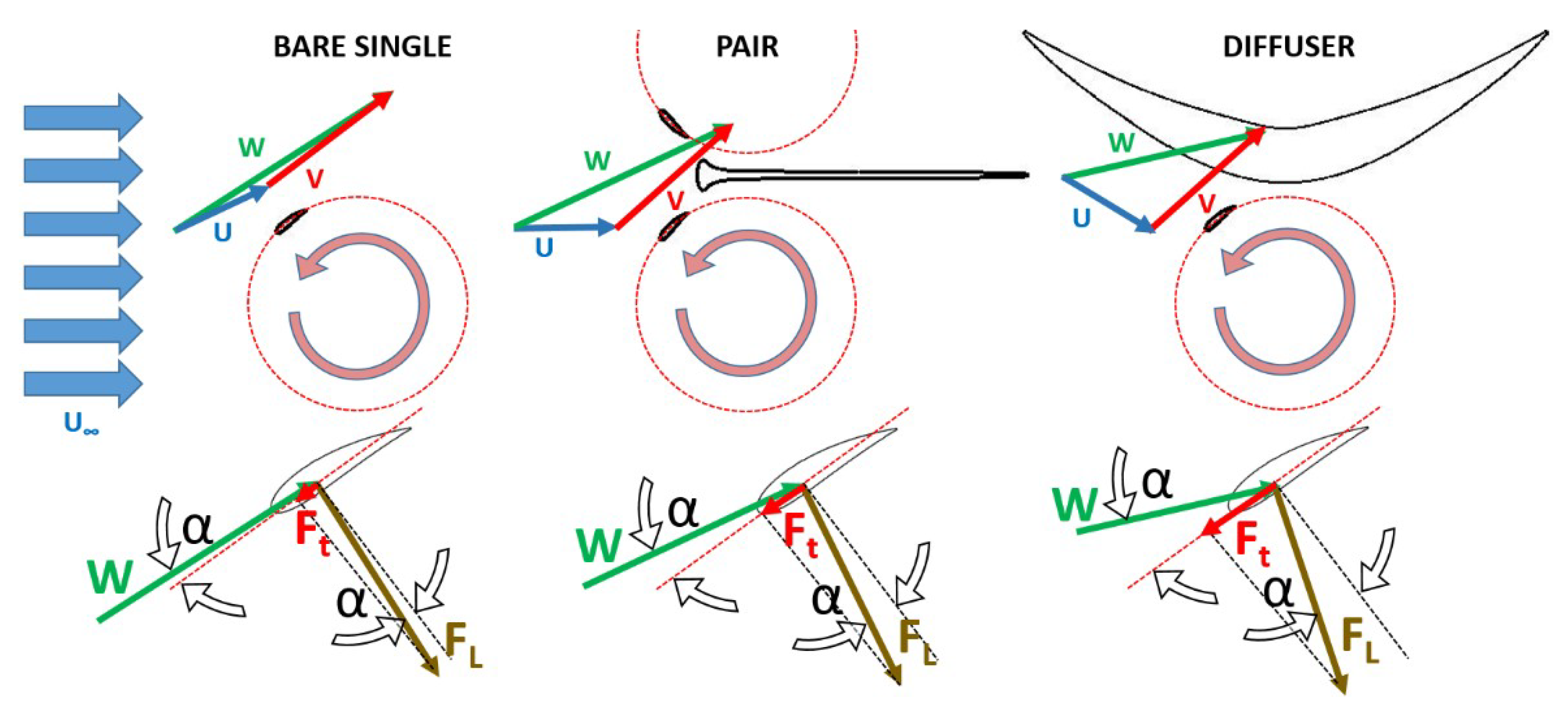
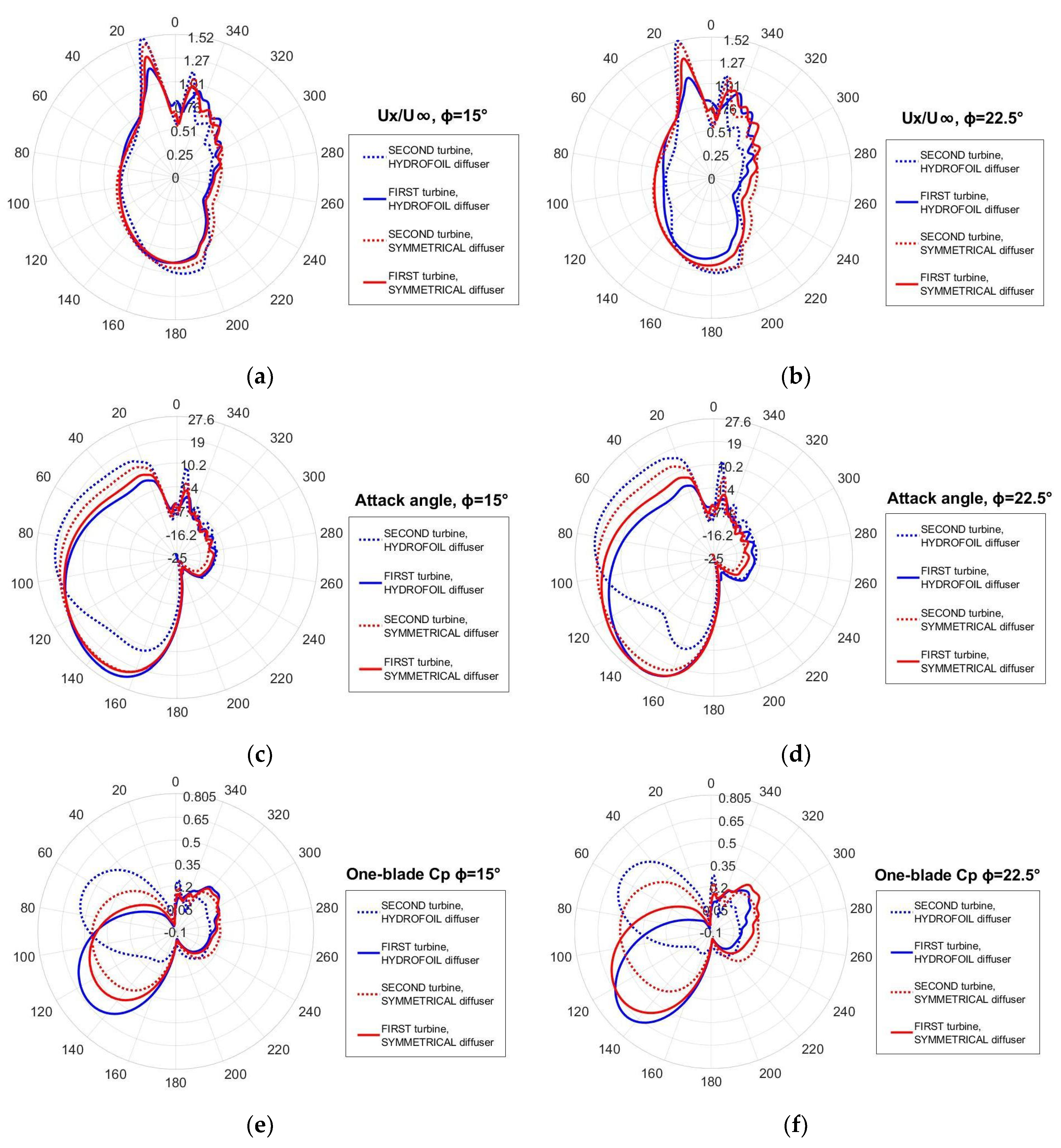
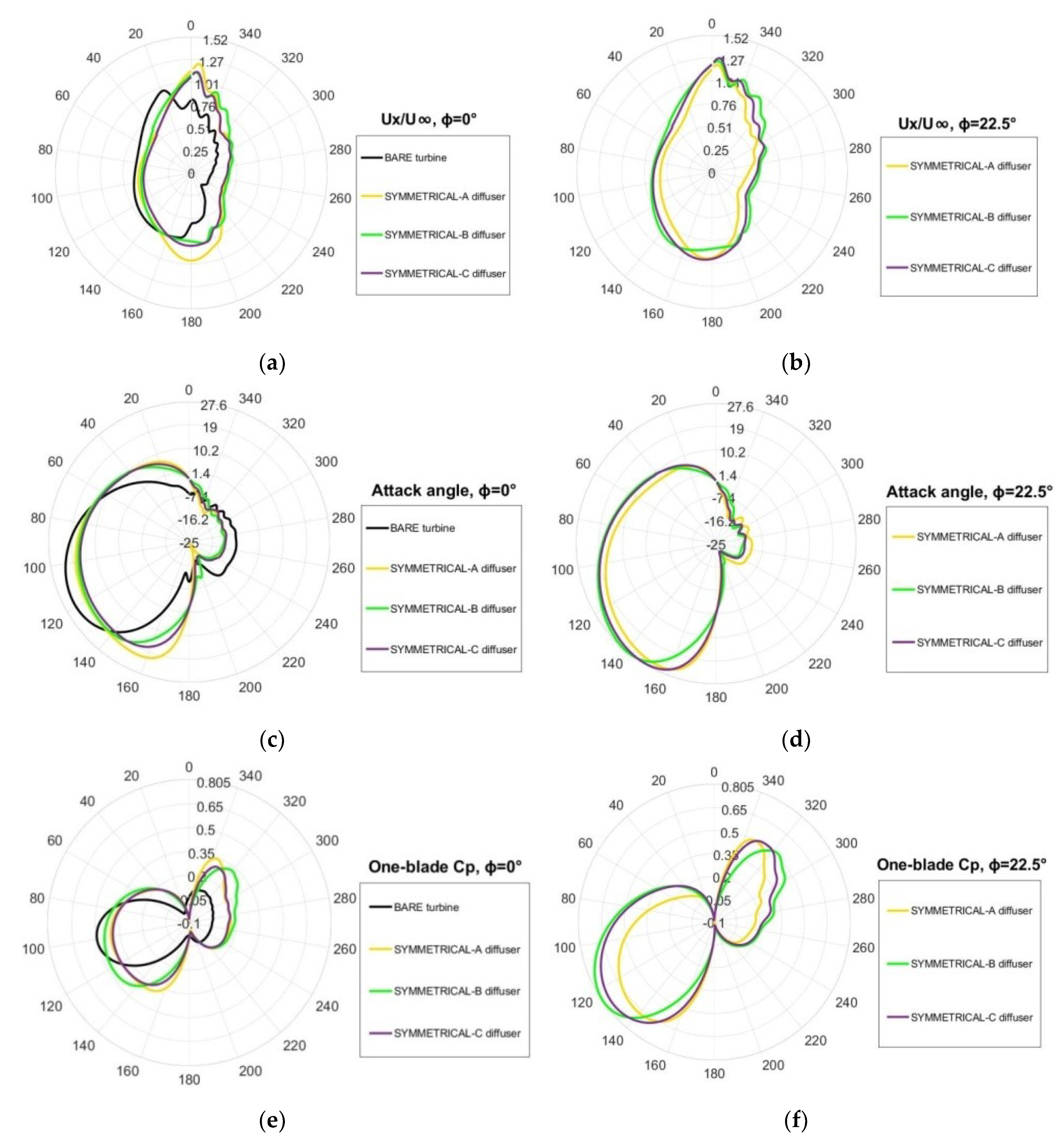
4.1. Importance of the Attack Angle

In CFTs most of the torque is generated upwind, since downwind the kinetic energy of the current is much lower due to upwind blade passage. The tangential force (Ft) that generates torque coincides with the tangential projection of the overall hydrodynamic force (sum of lift and drag) exerted by the fluid on the blade. Two parameters determine Ft, they are the flow apparent velocity (W) and the attack angle (α).
As depicted in Figure 7, W results from the vector composition of the absolute flow velocity (U) and the blade speed (V), whereas α is the angle between W and the chord. Since during one revolution the blade angular position changes, both α and W vary in a cyclic manner. W is maximum at ϑ = 0° (where the U module is added to the V module), and is minimum at ϑ = 180° (where U is subtracted from V). The highest values of α occur at ~90° and ~270°, and the lowest at ~0° and ~180°. The lift (Fl) and the drag (Fd) forces are responsible for the torque generated by the blade. However, Fd, which always opposes the blade motion, is relatively much smaller than Fl and thus it is here neglected for simplicity of treatment. Ft is greatly influenced by the instantaneous value of the attack angle. Indeed, the lift force on a wing of unitary span is
F l =   ρ π W 2 c sin α     W 2 α   ,
and therefore:
F t =   F l sin α     W 2 α 2   .
The above two relations are only valid in the pre-stall region, and for small values of α, for which sin(α) can be approximated whit α (in radians). Thus, a few degrees of increasing in α lead to a significant enhancing of the instantaneous torque. This would be helpful at the beginning and at the end of upwind, where α is very small not only because the blade chord is almost aligned to the free stream direction (x-axis), but also because the flow approaching the blade is x-directed only in the central part of upwind, while in early and late upwind it diverges laterally. This phenomenon (and the drag effects) justify why the blade of a single bare turbine starts to generate torque only at ϑ~30°.
Figure 7 gives a qualitative comparison of the velocity triangles and hydrodynamic forces when the blade is in early upwind (ϑ~40°) for three typical situations: a bare turbine, a turbine belonging to a closely spaced pair, a ducted turbine.
In the case of the turbine pair it can be observed that the presence of the upper turbine prevents the flow from diverging to the inner sides of the configuration, and therefore U results x-aligned, causing a significant increase of α and Ft [33,48], yet, the best torque is expected to be achieved by adopting a diffuser with a convergent section, since the diffuser wall direct U in a way that implies an even more great increasing of α [27,49]. One could object that the W vector is unfavourably shortened by any changing in the U direction that leads to a more favourable α. However, as can be seen looking at the velocity triangles of Figure 7, the W reduction appears very smaller respect to the α increasing. The reader can verify this by means of the following example. Let’s assuming ϑ = 30°, TSR = 1.9, UU (in reality, U is significantly smaller than U since the turbine slows down the flow as an obstacle partially permeable to the flow would do). Reasonable U angles with respect to the x-axis could be: 20° (flow divergent to the turbine side) for the bare turbine; 0° for the turbine pair; −20° (flow convergent to the turbine axis) for the ducted turbine. From the trigonometry laws it can be easily found that α is 2.77° for the single, 8.21° for the paired turbine and 13.29° for the ducted turbine, whereas W is 13.8 m/s, 13.5 m/s an 12.8 m/s, exhibiting a much lower sensitivity to the direction of the flow approaching the blade.

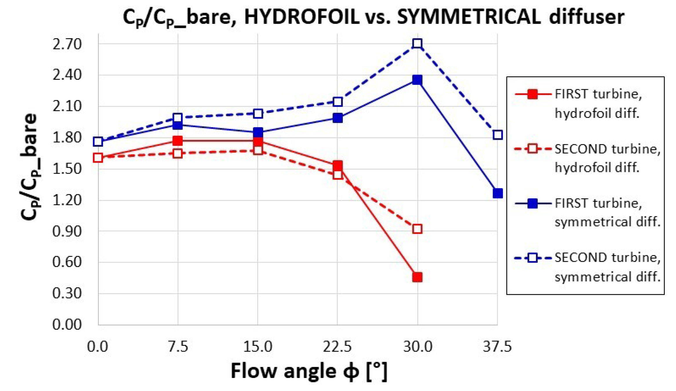
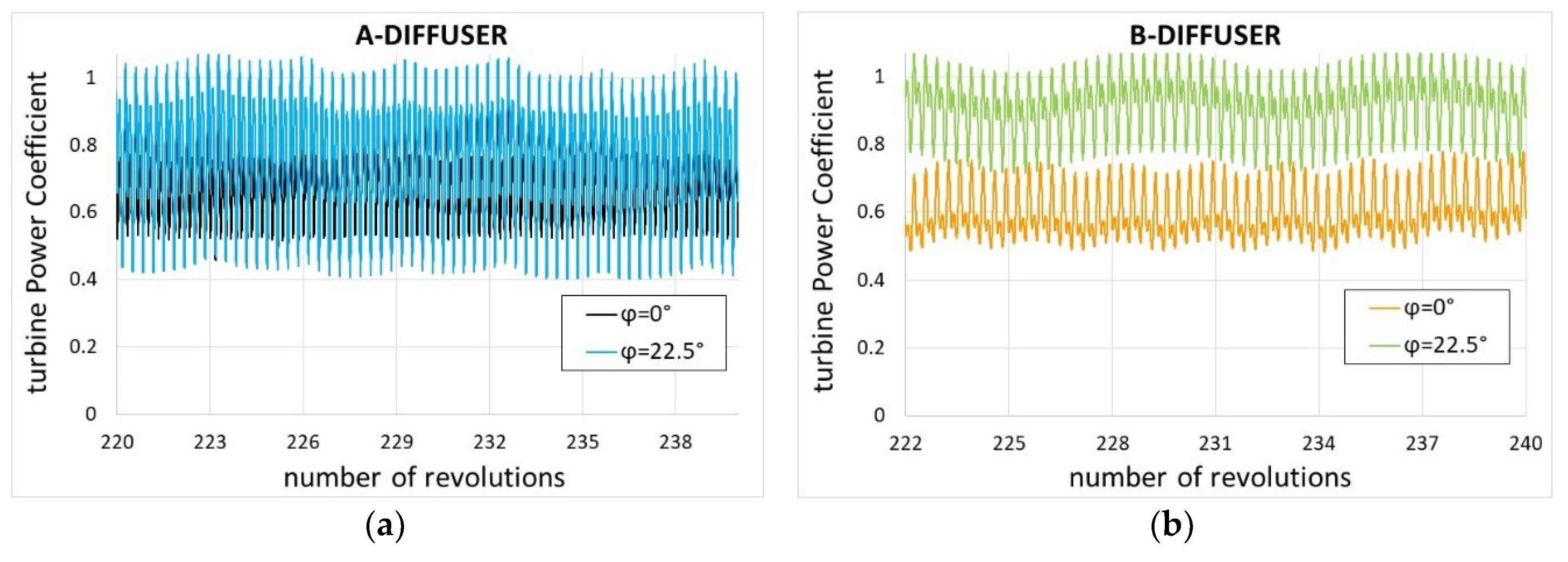
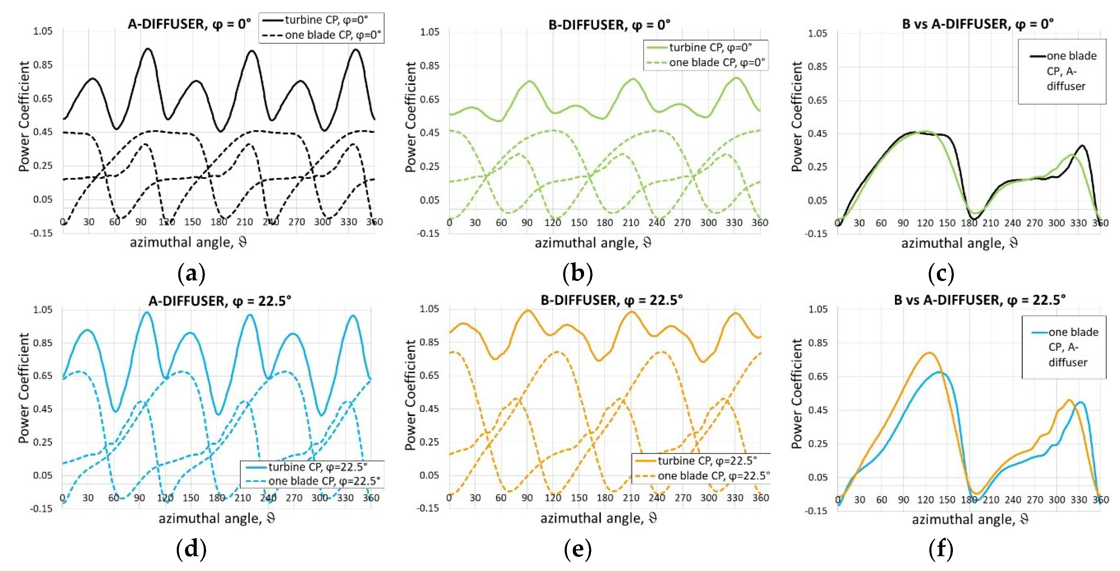
4.2. CP of the Turbine Pairs

A difficulty encountered by the designers of high performance diffusers is that the behaviour of an empty diffuser is completely different from that of a diffuser with a rotor working inside. Thus, numerical tools adopted to predict a new diffuser performance (CFD, or low order methods [29,30]) should also consider the turbine presence. Preliminary simulations of our diffusers (without turbines) predicted a slight flow separation in the final part of the inner walls for the hydrofoil shaped diffuser, and a massive separation for the symmetrical one leading to a 24% lower flow rate. Nevertheless, when turbines were inserted, neither the hydrofoil shaped nor the symmetrical diffuser showed any separation of the flow, as can be seen in Figure 8a, depicting details of the velocity map for the original diffuser. Scientists agree to attribute this trend to the effect of the high momentum jet establishing in the gap between the rotor and the duct wall when the turbine works [11,22,50,51]. This jet energizes the boundary layer in the adverse pressure gradient flow through the diffuser, suppressing trailing edge separation and therefore enhancing the turbine performance through a mechanism similar to circumferential blowing [52].
Another high momentum region occurs in the narrow aisle between the two rotors at both the sides of the central separation wall. For completeness, Figure 8b shows the turbulent kinetic energy map. Two high turbulence regions are visible, one being due to the vortices naturally shed by the blade at the beginning of downwind, the other being induced by the blunt head of the separation wall (see Figure 3b). However, only the second perturbs the torque production, as will be clarified in the following.
Figure 9 tries to justify the diffuser effect on the local flow speed (U) of the flow approaching the blade when its position varies during the revolution. At this purpose, the path-lines passing through the grid interface lines are shown for the bare turbine pair and for the ducted turbines. Despite only the symmetrical diffuser is treated, the following observations are valid in general. The path-lines set can roughly be considered the “stream tube” of the rotor pair. The stream tube’s width at a sufficient distance upstream the rotors is indicative of the flow rate processed by the turbines. Strictly speaking, the width measurement must be taken at the tube “source” (i.e., where free stream conditions occur).
By comparing the widths of the upstream part of the tubes of Figure 9a it is evident that ducted turbines are processing a much greater flow rate than bare turbines. Since the flow rate is constant along the stream tube for the continuity law, the local speed is inversely proportional to the stream tube cross-section. Thus, at the diffuser inlet, where the section appears very large, a flow speed even lower than in case of bare turbines is expected (in Figure 9a we indicated some relatively low speed zones with blue marks), and the same could happen after the diffuser exit. Focusing on the blade path, the highest U increasing respect to the bare turbines happens during downwind since local sections are equal (at ϑ = 180° and 360°) or even slightly smaller of the stream tube sections of the bare turbines (we indicated relatively high speed zones with red marks). In upwind the (relative) accelerating effect of the diffuser is much less intense and only relegated to the early and late upwind where stream tube sections are just slightly larger than in case of bare turbines. At half upwind, since the blade distance from the rotor axis is the highest and therefore the stream tube section can be significantly larger, the flow speed can result similar, or even lower, than in case of bare turbines. The velocity magnitude maps of Figure 9d confirm the above interpretation. In conclusion, the beneficial U increasing due to the diffuser action is much more effective in downwind than in upwind.
Figure 10 allows a qualitative comparison of the behaviour of the two diffuser types at different yaw angles.
Considering that the widths of the upstream stream tubes are representative of the flow rate passing through the turbines, the following general features are noticeable:
(1)
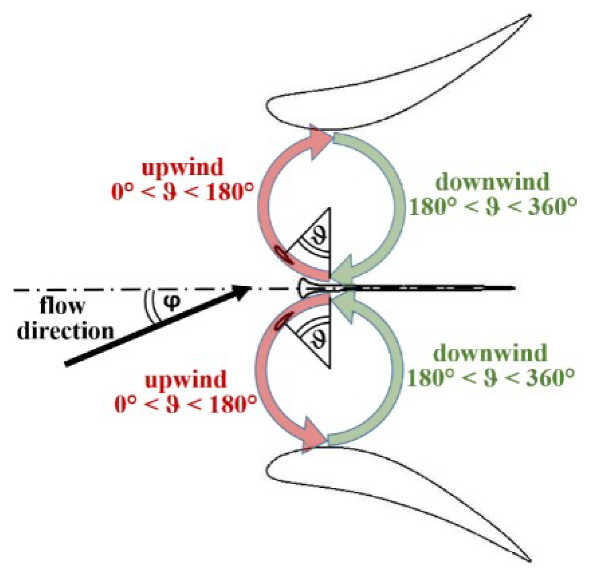
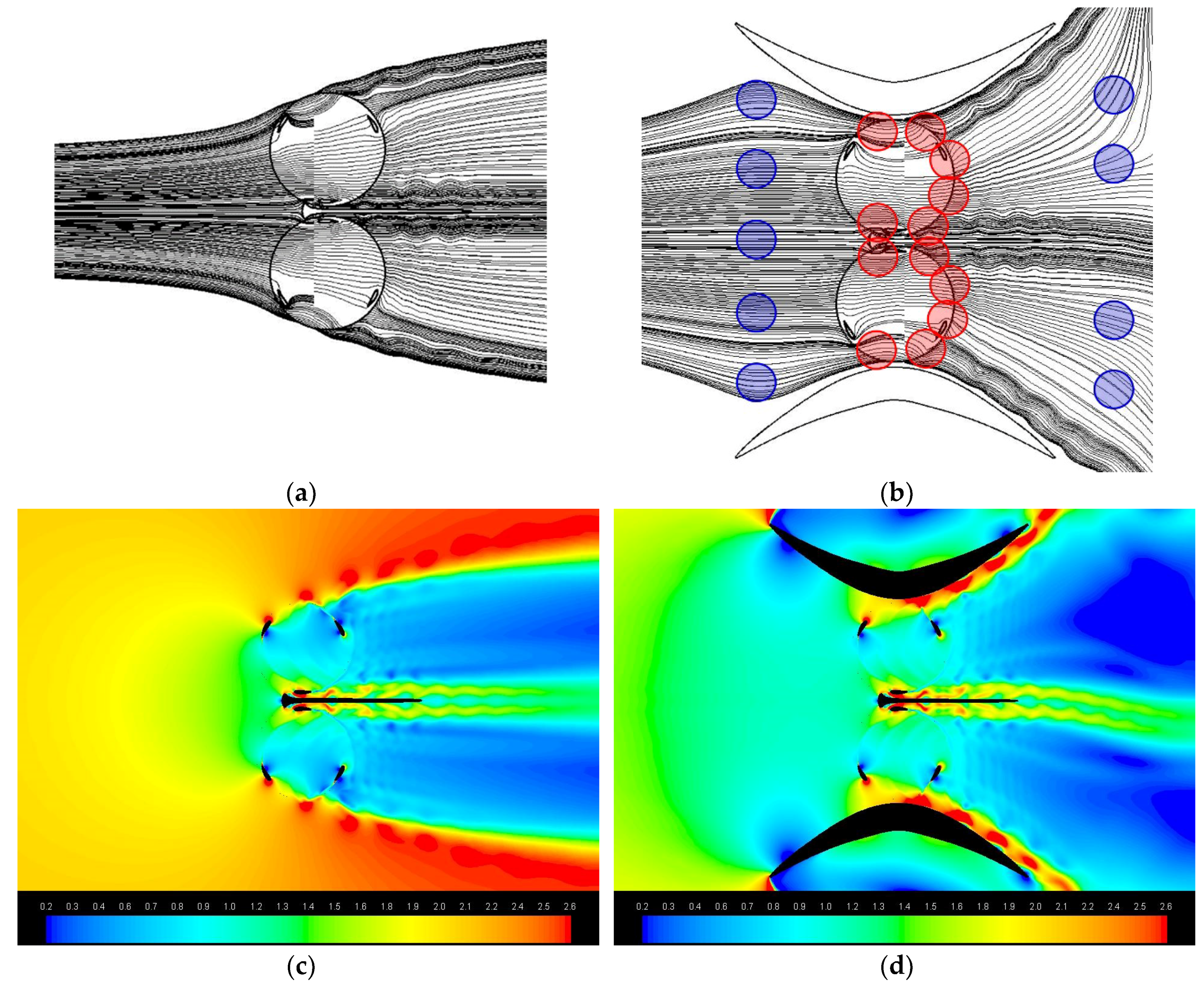
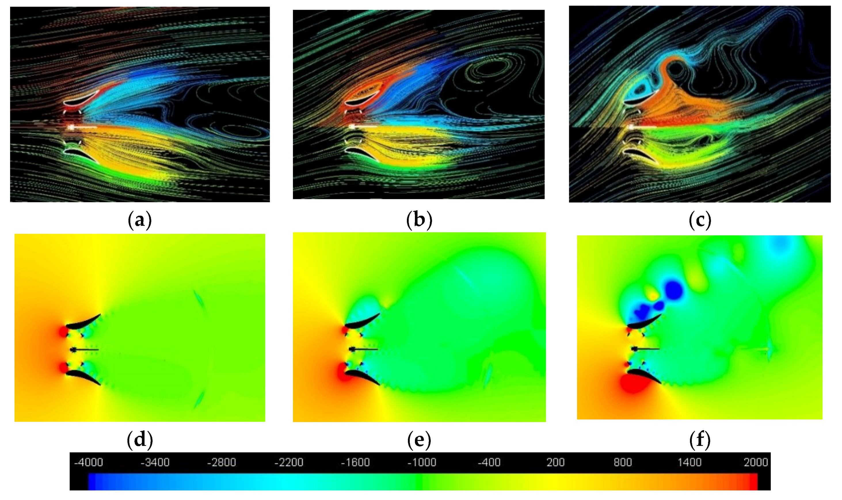
Taking into account the rotation direction of each turbine (shown in Figure 6) it is evident that the effect of the converging walls of the symmetrical diffuser occurs mainly during the final part of the blade upwind path. As demonstrated by the direction of the path-lines, this effect consists of an increase in the attack angle, whose consequences on lifting and torque have already been illustrated in Figure 7. It happens for both the rotors if φ = 0°, only for the “second turbine” (that is the upper one) if φ > 0°. The relative extent of this favourable effect (i.e., in comparison to what happens in the original diffuser) is greater the greater the yaw angle is.
(2)
For φ = 0°, the stream tube of the symmetrical diffuser appears larger (a measurement done at the domain inlet boundary revealed +3.5% respect to the original diffuser) indicating a better flow concentration capability.
(3)
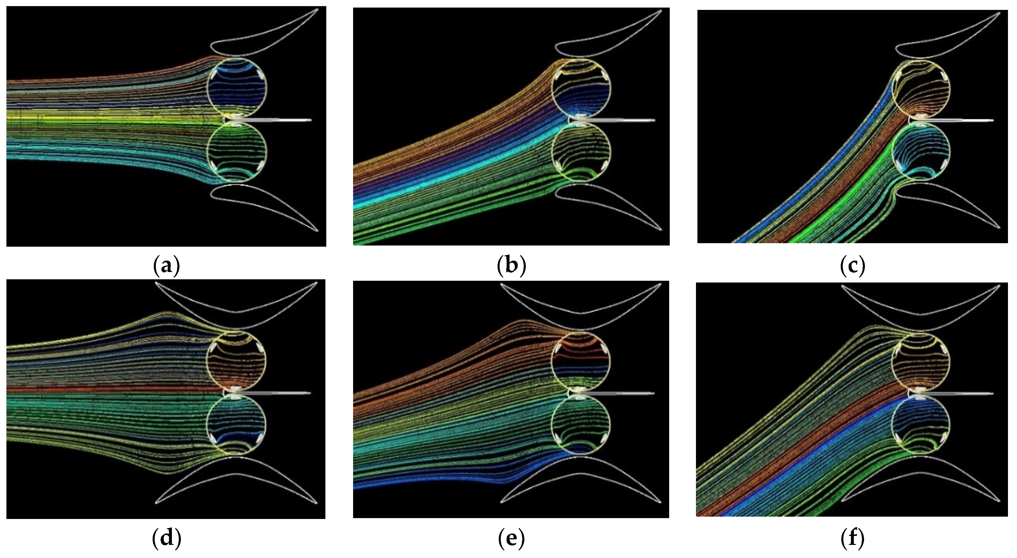
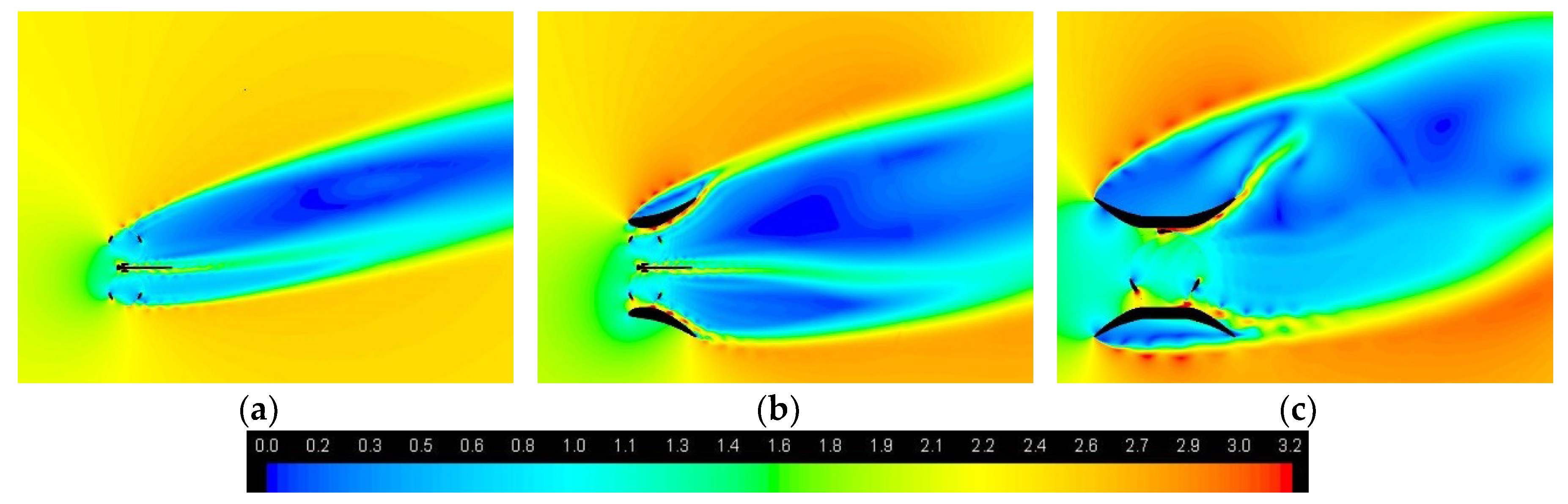
For the hydrofoil shaped diffuser the stream tube width slightly increases at φ = 15° but appears drastically narrowed at φ = 30°, while for the symmetrical diffuser the width continues surprisingly to grow up to φ = 30°.
In summary, a diffuser acts modifying α and U. It is worth noting that the effect marked with Equation (1) only concerns the fluid dynamics internal to the diffuser, whereas effects marked with Equations (2) and (3) need to be justified by accounting for the viscous phenomena occurring in the external flow, as will be better explained later in the section.
Despite the fact that for all the cases that have been investigated, the CP was higher the higher the stream tube width was measured, the diffuser accelerating capability alone cannot justify the formidable power output improving that have been calculated with CFD, especially for yawed flows. As shown by Castelli et al. [53] an effective way to asses and justify the energy performance of a straight-bladed CFT is to graphically represent the evolution of both the rotor torque (or CP(ϑ)) and blade angle of attack. Then, to deeply understand how the diffuser presence affects the key mechanisms that determine torque generation we analyse the polar diagrams of Ux(ϑ) and α(ϑ), and then the one-blade CP(ϑ) predicted during one revolution, shown in Figure 11 for φ = 0°.
It must be specified that α(ϑ) is determined from the x and y-components of the flow absolute velocity, Ux(ϑ) and Uy(ϑ), that are recorded along the blade path in a point moving simultaneously with the blade, and set at a proper distance ahead [33]. The best distance rises from a compromise, as the flow velocity is perturbed by both the bound circulation around the blade and by its wake. It was set at 1.5c on the base of a preliminary CFD investigation.
The graph of normalised U (i.e., U/U) confirms the aforementioned flow speed increasing in early and late upwind, and during the entire downwind, for both the diffusers in comparison to the single bare turbine. It is worthy of note that a U improving already occurs in the bare paired configuration in early upwind and late downwind [33,48].
The attack angle (Figure 11b) is high in the early upwind region for all the paired configurations, including the bare turbines [33,48], yet the diffusers also allow high α in the late upwind zone, especially in case of the symmetrical one (as already observed comparing the path-lines inclination in Figure 10a,d). It can be noticed that the diffusers also produce α augmentation (in absolute value) in downwind, however this is a consequence of the U increasing that modifies the velocity triangle.
The features of the one-blade CP graph (Figure 11c) follow those of the α graph: with both diffusers the torque generation begins earlier and lasts longer in upwind, and is significantly improved during the whole downwind. The detail that only appears in the CP graph, and therefore cannot be related to α or U, is a performance drop that occurs in the final 25° of downwind due to the high turbulence level generated by vortices released by the central wall (visible in Figure 8b). With respect to the single bare turbine, the average CP enhancing results of 30.9% for the bare paired rotors, and 63.7% and 70.3% for the hydrofoil shaped and the symmetrical diffusers, respectively.
Before analysing the polar graphs of yawed flow cases, it is useful to have a look at the characteristics of the flow field, focusing on the behaviour of the flow external to diffusers. Path-lines and static pressure maps are depicted in Figure 12 for the symmetrical and in Figure 13 for the original diffuser in case of φ = 0°, 15° and 30°.
A vortex formation like the Karman vortex street is seen downstream the trailing edges of the symmetrical diffuser at φ = 0°. As the yaw angle increases, the vortex shedding becomes asymmetric: it almost expires at the upstream side of the diffuser, and conversely becomes stronger and stronger at the downstream side, entailing a very low pressure zone behind the diffuser. The vortex shedding from the original diffuser is much less important, being significant only for φ = 15° and 30°, yet the low pressure zones behind the diffuser are less extended and modest in absolute values. In our opinion, these differences in the external fluid dynamics could explain the different flow acceleration attitudes, and therefore flow rate passing through turbines, exhibited by the two diffusers. The literature on ducted turbines gives evidence of how viscous interactions between internal and external flows can be advantageously exploited to achieve a remarkable increasing of the flow concentration capability in diffusers equipped with deflectors [26] or flanges [54,55] at the exit periphery. The mechanism of flow acceleration was explained as follows [55]: a large vortex is generated behind a flange and the backpressure of the diffuser becomes lower than that of a diffuser without a flange. Therefore, the mass flow drawn into the diffuser increases and the flow speed through the turbine becomes high. Although we don’t have a flange, strong vortices at the diffuser sides occur thanks to the concave external shape of the symmetrical diffuser. These vortices boost the suction in the turbine wakes, as suggested by the rear stagnation points of the diffuser (i.e., where internal and external flows meet) that are moved forward, farther from the diffuser axis, as if virtually the aspect ratio of diffuser was enlarged. This can be realized comparing the rear stagnation point positions of Figure 12a,b.
Let’s now analyse the polar graphs of yawed cases in Figure 14, limiting to ϕ = 15° an 22.5° for brevity. About U, at φ = 15° both the diffusers benefit from viscous interactions between internal and external flows (exhibiting a flow rate slightly greater than in case of φ = 0°), whereas at φ = 22.5° this only happens for the symmetrical diffuser.
About α, it is considerably smaller during late upwind for the second turbine of the original diffuser, and this deficiency is higher the higher the yaw angle is. This is because the original diffuser is not equipped with a converging wall capable of holding back the flow from the exit towards the device side and orient it to the rotor with a favourable entry angle. As a result, CP are similar at φ = 15°, yet very different at φ = 22.5°.
The arguments presented so far are useful to understand the results summarised in Figure 15, which shows the performance of each rotor of the pair in terms of diffuser efficiency (CP normalised by the bare turbine CP). It is seen that, at any yaw angle, the symmetrical diffuser has a performance higher than that of the original diffuser. In case of symmetrical diffuser, the performance of the second rotor overcomes that of the first rotor, and CP grows up to φ = 30° (exhibiting a drastic drop at φ = 37.5°). Whereas, for the hydrofoil shaped diffuser, the first rotor works better than the second, and CP improves up to φ = 15°, then it starts to drop. It is interesting to notice that the enhancing of the diffuser performance with φ was never found in case of ducted horizontal axis turbines, which at least exhibit a constant CP (or just a small drop) until a certain φ.

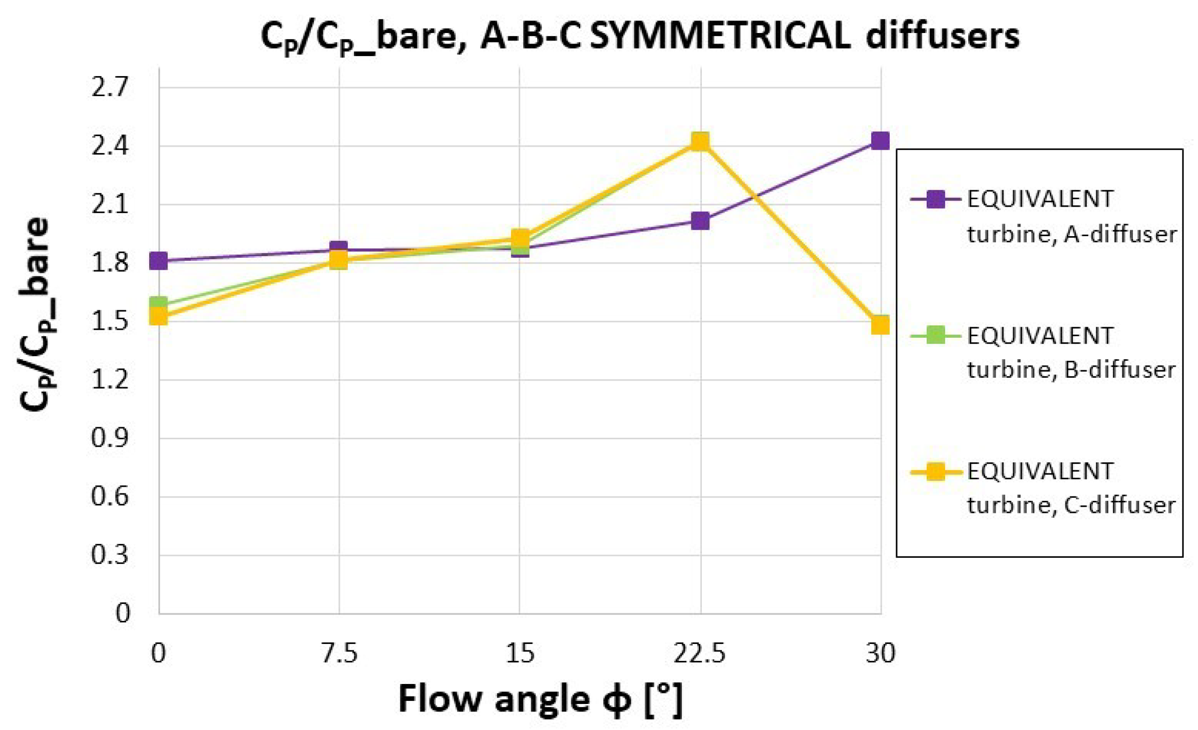
4.3. CP of the Equivalent Turbine
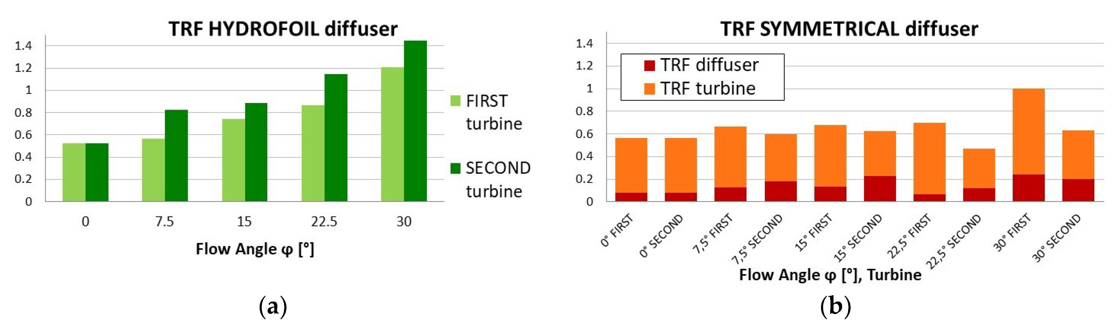
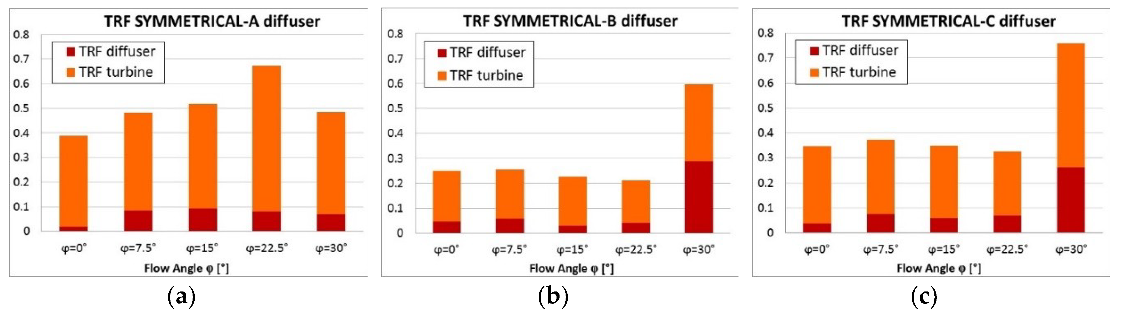
It must be specified that, due to the larger size (D* = 2.15D) and therefore larger Reynolds number, the bare equivalent turbine gives a better CP by 8.0%. The effects of the diffuser geometry at different yaw angles have been investigated. This analysis is limited to symmetrical diffusers, since they are bi-directional and furthermore the symmetrical diffuser (named diffuser A in the following) that has been simulated for the double-rotor configuration provided better CP at any yaw angle. The diffuser efficiencies calculated for A (Figure 16) are similar in values and trend to those that have been found for the ducted paired configuration. Then we can conclude that the power output increasing with the yaw angle is a general characteristic of ducted CFTs, regardless of the (single or double-rotor) configuration. As mentioned, B and C have the same aspect ratio (exit section/throat section) of A, therefore in absence of viscous effects they should all accelerate the flow in the same manner. Yet, the features of the diffuser external shape entail different vortex structures and then backpressures in the rotor wakes. However it is difficult to distinguish the contribution of Ux and α (i.e., of the external and internal fluid dynamics) on CP values resumed in Figure 16.
It is intuitive that A is able to direct the flow towards the blade with a better angle than B and C during early and late upwind, and this effect should work at any yaw angle (the reader can recognize it in Figure 17c for φ = 0°). However, the better CP at 22.5° followed by a remarkable drop at 30° shown by B and C in comparison to A, suggests that in those cases the main role is played by viscous effects, as it is argued comparing Ux of the three diffusers at φ = 22.5° (Figure 16). In conclusion, considering only CP the best diffuser would seem A, yet practical issues need to be counted for.

4.4. Torque Ripple

The periodic fluctuation of torque and power is a characteristic of any CFT that should be mitigated as much as possible. To quantify the fluctuation a parameter is used, named Torque Ripple Factor (TRF), defined as:
T R F =   T m a x T m i n T   , T R F =   T m a x T m i n T   ,
where T, Tmax and Tmin are the average, the lowest and the highest instantaneous torque in the period. For bare turbines the period is one revolution, yet for ducted turbines the vortex shedding can entail much longer periods (of the order of 10 revolutions). When this happens (in our study, only with symmetrical diffusers) it is useful to distinguish the contributions of turbine and diffuser to the overall TRF. We calculated the former on two consecutive pick and trough, and the latter as the remaining part of the overall TRF. The TRF of ducted pairs is shown in Figure 18 for the original and the symmetrical diffusers. Results indicate that the symmetrical diffuser, despite the contribution of the diffuser to the ripple, implies lower (with the exception of φ = 0°) and almost constant TRF when yaw angle changes. However, since the denominator of TRF grows with φ, also absolute fluctuations rise (with very high values at φ = 22.5° and 30°).
Thus, any modification to the diffuser shape reducing both absolute and relative fluctuations would be useful. At this purpose we now compare the torque ripple behaviour of symmetrical diffusers A, B and C (Figure 19). It is seen that A leads to much higher TRF than B and C, and that B results the best shape, since it is able to maintain TRF al low values until φ ≤ 22.5°, as shown in Figure 20, which allows to compare the power fluctuation behaviour of the A and B diffusers for yaw angles of 0° and 22.5°.
Figure 21 explains the reasons for the TRF differences found for A and B at φ = 0° and 22.5°. In one revolution six peaks occur in the CP curve, this is because the blades are three and each one produces torque in upwind and downwind. One-blade CP of each blade are also reported (dashed lines). CP at a certain ϑ is the sum of the three one-blade values. In general, to suppress TRF it is desirable to level peaks and troughs, bringing them closer to the average torque. The main reasons for the drastic TRF reduction exhibited by B is a great rising of troughs and, only in case of φ = 0°, a reduction of peaks. Figure 21c,f reveal why the “smoothing out” of the turbine CP curve can occur. The straight throat inserted in B causes a reduction of α in early and late upwind and an Ux increasing in downwind (due to the cross section narrowing).
As a consequence, at φ = 0° less torque is generated in early and late upwind (leading to a reduction of peaks) and more torque is generated at half downwind (leading to an increasing of troughs). However, the huge rising of troughs found at φ = 22.5° is also due to a much higher flow rate of B respect to A (noticeable in Figure 17b), that improves the one-blade torque at ϑ = 120° and 290°.

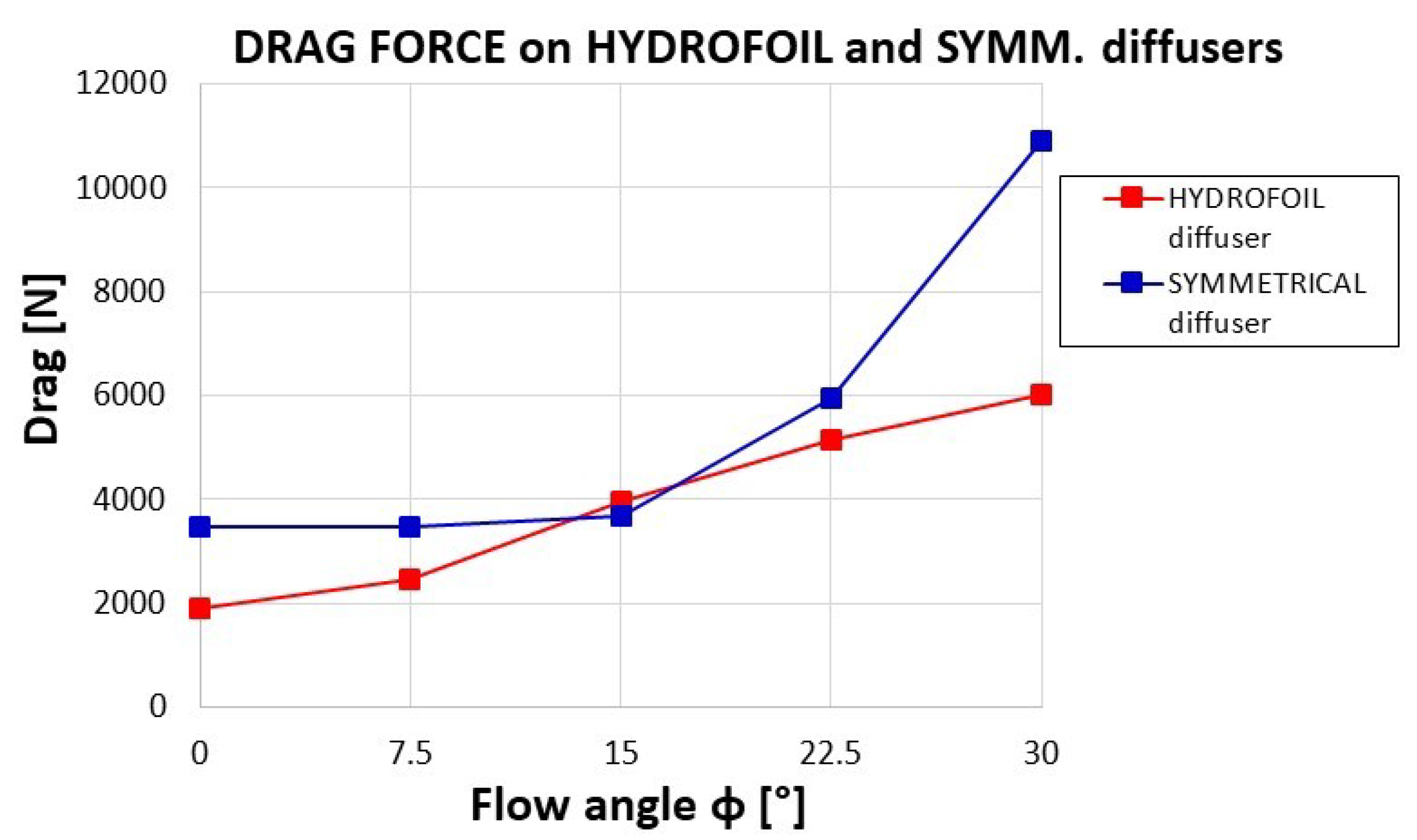
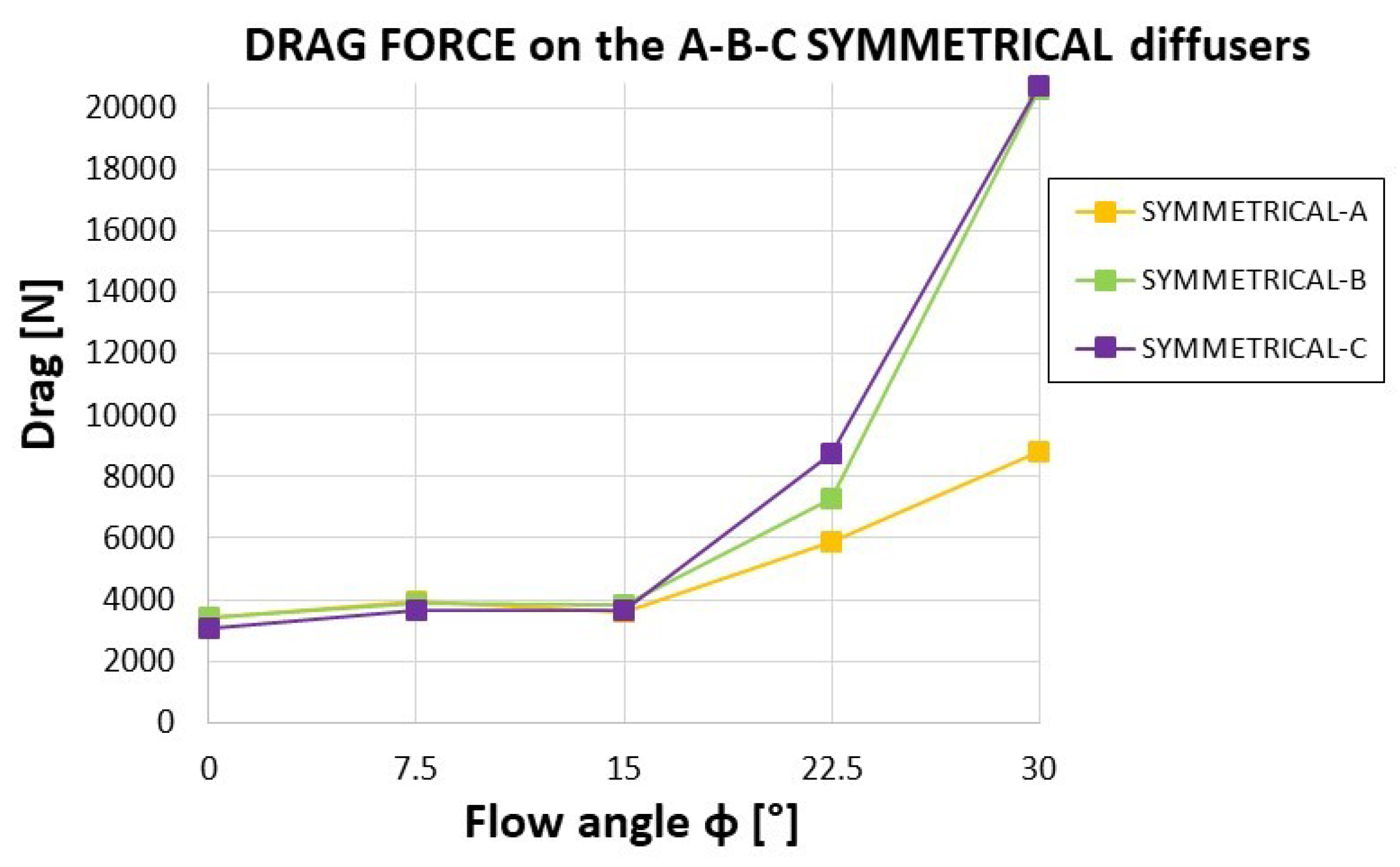
4.5. Drag on the Diffuser
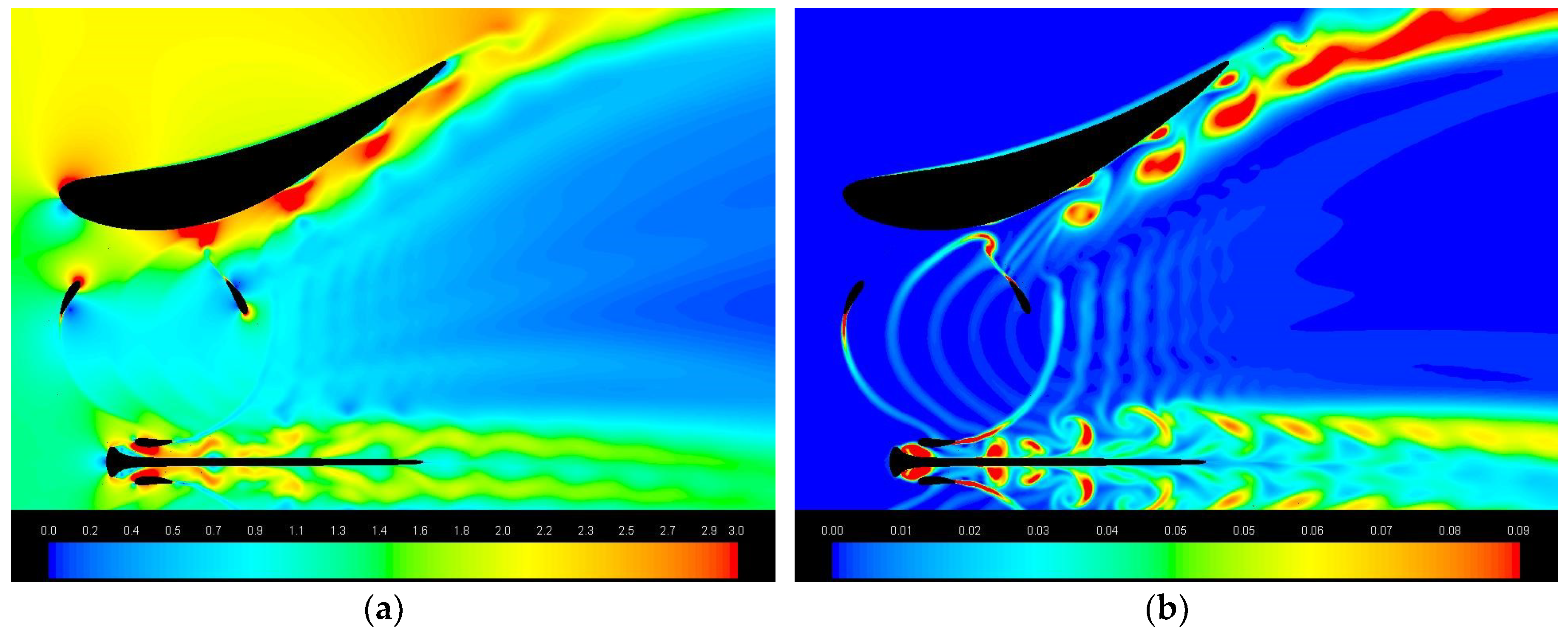
Diffusers add costs since they imply more materials and heavy support structures to take the loads expected in storm conditions. Despite part of the overall drag (or thrust) on the diffuser is correlated to its flow accelerating capability and to the turbine presence, and therefore cannot be cut, the necessity of reducing the device cross section as much as possible in yawed flow conditions should lead to a preference for short geometries. Figure 22 shows that the overall drag (i.e., force in the flow direction) on the original and symmetrical diffusers seriously rises when yaw ≥ 15°. Moreover, the symmetrical diffuser, due to its almost double length, entails higher drag at any yaw angle (except for 15°). Figure 23 allows to compare the drag on bi-directional diffusers A, B and C. It is interesting to observe that the drag is very similar for all the diffusers and it doesn’t grow until φ = 15°, while at φ = 22.5° and 30° a huge increase is found for the longer diffusers (B and C).
All the results (CP, TRF and drag) are summarised in Table 1 for double-rotor and in Table 2 for single rotor configurations.

4.6. Wakes

There are no studies on wake recovery of ducted CFTs. Cresswell [22] founded very poor wake recovery in the case of ducted horizontal axis turbines, with the wake velocity being less than half that of the bare rotor at 4.5D downstream. Therefore he observed that diffuser augmented turbines seem to be less suited to array deployment than bare rotors, unless measures are taken to promote wake mixing. In comparison to bare rotors, ducted CFTs imply much larger wakes, characterised by high turbulence levels, as shown by the velocity and turbulent kinetic energy maps of Figure 24 and Figure 25, calculated at φ = 15°. Especially in case of symmetrical diffusers, since they behave like a blunt body, the diffuser gives the main contribution to the turbulence. Thus, in optimizing the layout of a farm, cross and streamwise extra spacing could be required to prevent the turbines from being swept from the wakes of the lateral or upstream devices. However, 2D CFD could not be reliable in predicting the wake evolution in streamwise direction. In fact, 2D CFD overvalues wake length of bare CFTs, since it doesn’t account for 3D mechanisms responsible for wake recovery, first of all the vertical advection induced by tip vortices [42], yet, large tip vortices are not possible for ducted CFTs due to small gaps between blade tip and diffuser walls, so this critical issue remains open.

5. Conclusions

The study examines the behaviour of ducted cross flow tidal turbines when the yaw angle varies. Initially, we considered a double-rotor configuration with two diffuser shapes: the HARVEST hydrofoil shaped diffuser and a symmetrical diffuser obtained through a specular copy of the divergent section. The intrinsic advantage of the symmetrical diffuser is to be bi-directional, i.e., able to exploit ebb and flow tides with the same efficiency. Thereafter, we extended the investigation on the diffuser geometry effects to other two symmetrical geometries.
From a methodological point of view, this study shows that an effective way to understand the effects of the diffuser shape on power output is to graphically represent the azimuthal distribution of blade attack angle and flow x-velocity at the blade position, together with the instantaneous one-blade CP. Indeed, α is influenced by the diffuser internal shape, and Ux is determined by the accelerating capability of the diffuser. Our comparative analysis predicts slightly better CP for the symmetrical diffuser, due to the walls of the convergent section that address the flow towards the blade with a larger attack angle during early and late upwind and to the viscous interactions between the turbine wakes and the strong vortices shed by the diffuser. A CP great improvement results when yaw increased up to 22.5° for the hydrofoil shaped and up to 30° for the symmetrical diffuser. Similar behaviour in yawed flow conditions also occurs in case of a ducted single rotor, demonstrating that it is a characteristic of CFTs that could make them advantageous compared to ducted horizontal axis turbines.
Diffusers imply extra-costs and practical disadvantages. Torque fluctuations can increase significantly if large vortices occur at the sides or behind the device. This happens in case of concave external shapes or in case of large yaw angles, for which the device behaves like a blunt body. Therefore, a diffuser geometry should be optimised in order to contain this problem as much as possible. The insertion of a straight throat in the symmetrical diffuser successfully mitigated torque ripple, however the attack angle reduction in early and late upwind generated a CP loss. We also quantified the overall drag on diffusers. The extra-length of the last two diffusers increased drag only for yaws ≥ 22.5°. Finally, we displayed that wakes are hugely larger than in case of bare turbines, and characterised by high turbulence levels mainly caused by the diffuser vortex shedding. Although 2D simulations are not suitable to investigate wake recovery mechanisms, our results indicate the need to increase the spacing between the devices in planning the layout of a multi-device arrangement.

Author Contributions

All the authors equally contributed to validation, investigation, formal analysis, and writing of the original draft preparation; S.Z. was responsible for conceptualization, methodology and supervision, moreover she proceeded to revise the article.

Funding

This research did not receive any specific grant from funding agencies in the public, commercial, or not-for-profit sectors.

Conflicts of Interest

The authors declare no conflict of interest.

Nomenclature

Latin symbols
ARturbine aspect ratio [-]
Bnumber of blades [-]
CFTcross flow turbine
CPpower coefficient [-]
Dturbine diameter [m]
D*equivalent turbine diameter [m]
Hblade length [m]
Rturbine radius [m]
Ttorque [Nm]
TSRtip speed ratio [-]
TRFtorque ripple factor [-]
Ufree stream velocity magnitude [m/s]
Uxabsolute x-velocity at blade position [m/s]
Uyabsolute y-velocity at blade position [m/s]
Wflow apparent velocity [m]
y+dimensionless wall distance [-]
Greek symbols
αangle of attack [°]
ϑblade azimuthal angle [°]
ρair density [kg/m3]
σblade solidity [-]
φyaw angle of the current [°]
Ωturbine angular velocity [rad/s]

References

  1. Scheurich, F.; Brown, R. Vertical-axis wind turbines in oblique flow: Sensitivity to rotor geometry. In Proceedings of the EWEA Annual Event, Brussels, Belgium, 14–17 March 2011. [Google Scholar]
  2. Bedon, G.; De Betta, S.; Benini, E. A computational assessment of the aerodynamic performance of a tilted Darrieus wind turbine. Wind Eng. Ind. Aerodyn. 2015, 145, 263–269. [Google Scholar] [CrossRef]
  3. Chowdury, A.M.; Akimoto, H.; Hara, Y. Comparative CFD analysis of Vertical Axis Wind Turbine in upright and tilted configuration. Renew. Energy 2016, 85, 327–337. [Google Scholar] [CrossRef]
  4. Dabiri, J.O. Potential order-of-magnitude enhancement of wind farm power density via counter-rotating vertical-axis wind turbine arrays. J. Renew. Sustain. Energy 2011, 3, 043104. [Google Scholar] [CrossRef] [Green Version]
  5. Kinzel, M.; Mulligan, Q.; Dabiri, J.O. Energy exchange in an array of vertical-axis wind turbines. J. Turbul. 2012, 13, 1–13. [Google Scholar] [CrossRef]
  6. Vergaerde, A.; De Troyer, T.; Kluczewska-Bordier, J.; Parneix, N.; Silvert, F.; Runacres, M.C. Wind tunnel experiments of a pair of interacting vertical-axis wind turbines. In IOP Conf. Series: Journal of Physics; IOP Publishing: Bristol, UK, 2018; Volume 1037, p. 072049. [Google Scholar]
  7. Foreman, K.M.; Gilbert, B.; Oman, R.A. Diffuser augmentation of wind turbines. Sol. Energy 1977, 20, 305–311. [Google Scholar] [CrossRef]
  8. Igra, O. Research and development for shrouded wind turbines. Energy Convers. Manag. 1981, 21, 13–48. [Google Scholar] [CrossRef]
  9. Flay, R.; Nash, T.; Phillips, D. Aerodynamic Analysis and Monitoring of the Vortec7 Diffuser Augmented Wind Turbine; Institution of Professional Engineers New Zealand: Wellington, New Zealand, 1998. [Google Scholar]
  10. Van Bussel, G.J.W. An assessment of the performance of diffuser augmented wind turbines (DAWTs). In Proceedings of the ASME Joint Engineering Fluid Conference, San Francisco, CA, USA, 18–23 July 1999. [Google Scholar]
  11. Hansen, M.O.L.; Sørensen, N.N.; Flay, R.G.J. Effect of Placing a Diffuser around a Wind Turbine. Wind Energy 2000, 3, 207–213. [Google Scholar] [CrossRef]
  12. Ohya, Y.; Uchida, T.; Karasudani, T.; Hasegawa, M.; Kume, H. Numerical studies of flow around a wind turbine equipped with a flanged-diffuser shroud using an actuator-disc model. Wind Eng. 2012, 36, 455–472. [Google Scholar] [CrossRef]
  13. Goltembott, U.; Ohya, Y.; Yoshida, S.; Jamieson, P. Aerodynamic interaction of diffuser augmented wind turbines in multi-rotor systems. Renew. Energy 2017, 112, 25–34. [Google Scholar] [CrossRef]
  14. OpenHydro Group Ltd. Available online: www.openhydro.com (accessed on 19 December 2014).
  15. Lunar Energy. Available online: www.lunarenergy.co.uk (accessed on 19 December 2014).
  16. Atlantis Resources. Available online: http://atlantisresourcesltd.com (accessed on 21 December 2014).
  17. Clean Current Power Systems Inc. Available online: www.cleancurrent.com (accessed on 22 December 2014).
  18. Fleming, C.F.; Willden, R.H.J. Analysis of bi-directional ducted tidal turbine performance. Int. J. Mar. Energy 2016, 16, 162–173. [Google Scholar] [CrossRef]
  19. Allsop, S.; Peyrard, C.; Thies, P.R.; Boulougouris, E.; Harrison, G.P. Hydrodynamic analysis of a ducted open centre tidal stream turbine using blade element momentum theory. Ocean Eng. 2017, 141, 531–542. [Google Scholar] [CrossRef]
  20. Blunden, L.S.; Batten, W.M.J.; Bahaj, A.S. Comparing Energy Yields from Fixed and Yawing Horizontal Axis Marine Current Turbines in the English Channel. In Proceedings of the ASME 27th International Conference on Offshore Mechanics and Arctic Engineering, Esturil, Portugal, 15–20 June 2008. [Google Scholar]
  21. Frost, C.H.; Evans, P.S.; Harrold, M.J.; Mason-Jones, A.; O’Doherty, T.; O’Doherty, D.M. The impact of axial flow misalignment on a tidal turbine. Renew. Energy 2017, 113, 1333–1344. [Google Scholar] [CrossRef]
  22. Cresswell, N.W.; Ingram, G.L.; Dominy, R.G. The impact of diffuser augmentation on a tidal stream turbine. Ocean Eng. 2015, 108, 155–163. [Google Scholar] [CrossRef] [Green Version]
  23. Phillips, D.G. An Investigation on Diffuser Augmented Wind Turbine Design. Ph.D. Thesis, University of Auckland, Auckland, New Zealand, 2003. [Google Scholar]
  24. Foreman, K.M.; Gilbert, B.L. Further Investigations of Diffuser Augmented Wind Turbines Parts I and II; Grumman Research Department: New York, NY, USA, 1979. [Google Scholar]
  25. Münch-Alligné, C.; Schmid, J.; Richard, S.; Gaspoz, A.; Brunner, N.; Hasmatuchi, V. Experimental Assessment of a New Kinetic Turbine Performance for Artificial Channels. Water 2018, 10, 311. [Google Scholar] [CrossRef]
  26. Ponta, F.; Dutt, G.S. An improved vertical-axis water-current turbine incorporating a channeling device. Renew. Energy 2000, 20, 223–241. [Google Scholar] [CrossRef]
  27. Malipeddi, A.R.; Chatterjee, D. Influence of duct geometry on the performance of Darrieus hydroturbine. Renew. Energy 2012, 43, 292–300. [Google Scholar] [CrossRef]
  28. Geurts, B.; Simão Ferreira, C.J.; Van Zuijlen, A.; Van Bussel, H. Aerodynamic Analysis of a Vertical Axis Wind Turbine in a Diffuser. In Proceedings of the 3rd EWEA Conference—Torque 2010: The Science of making Torque from Wind, Heraklion, Greece, 28–30 June 2010. [Google Scholar]
  29. Letizia, S.; Zanforlin, S. Hybrid CFD-source Terms Modelling of a Diffuser-augmented Vertical Axis Wind Turbine. Energy Procedia 2016, 10, 1280–1287. [Google Scholar] [CrossRef]
  30. Dominguez, F.; Achard, J.-L.; Zanette, J.; Corre, C. Fast power output prediction for a single row of ducted cross-flow water turbines using a BEM-RANS approach. Renew. Energy 2016, 8, 658–670. [Google Scholar] [CrossRef]
  31. Achard, J.L.; Imbault, D.; Tourabi, A. Turbine Engine with Transverse-Flow Hydraulic Turbine Having Reduced Total Lift Force. U.S. Patent US8,827,631 (B2), 9 September 2014. [Google Scholar]
  32. Zanforlin, S.; Burchi, F.; Bitossi, N. Hydrodynamic interactions between three closely-spaced vertical Axis tidal turbines. Energy Procedia 2016, 101, 520–527. [Google Scholar] [CrossRef]
  33. Zanforlin, S. Advantages of vertical axis tidal turbines set in close proximity: A comparative CFD investigation in the English Channel. Ocean Eng. 2018, 156, 358–372. [Google Scholar] [CrossRef]
  34. Maître, T.; Amet, E.; Pellone, C. Modeling of the flow in a Darrieus water turbine: Wall grid refinement analysis and comparison with experiments. Renew. Energy 2013, 51, 497–512. [Google Scholar] [CrossRef]
  35. Marsh, P.; Ranmuthugala, D.; Penesis, I.; Thomas, G. Three-dimensional numerical simulations of straight-bladed vertical axis tidal turbines investigating power output, torque ripple and mounting forces. Renew. Energy 2015, 83, 67–77. [Google Scholar] [CrossRef] [Green Version]
  36. Li, C.; Zhu, S.; Xu, Y.; Xiao, Y. 2.5D large eddy simulation of vertical axis wind turbine in consideration of high angle of attack flow. Renew. Energy 2013, 51, 317–330. [Google Scholar] [CrossRef] [Green Version]
  37. Castelli, M.R.; Monte, A.D.; Quaresimin, M.; Benini, E. Numerical evaluation of aerodynamic and inertial contributions to Darrieus wind turbine blade deformation. Renew. Energy 2013, 51, 101–112. [Google Scholar] [CrossRef]
  38. Lain, S.; Osorio, C. Simulation and evaluation of a straight-bladed Darrieus-type cross flow marine turbine. J. Sci. Ind. Res. 2010, 69, 906–912. [Google Scholar]
  39. Menter, F.R. Zonal two equation k-ω turbulence models for aerodynamic flows. In Proceedings of the 24th Fluid Dynamics Conference, Orlando, FL, USA, 6–9 July 1993. AIAA Paper 93-2906. [Google Scholar]
  40. Menter, F.R. Two-equation eddy-viscosity turbulence models for engineering applications. AIAA J. 1994, 32, 1598–1605. [Google Scholar] [CrossRef] [Green Version]
  41. Wilcox, D.C. Formulation of the k-ω turbulence model revisited. AIAA J. 2008, 46, 2823–2838. [Google Scholar] [CrossRef]
  42. Bachant, P.; Wosnik, M. Modeling the near-wake of a vertical-axis cross-flow turbine with 2-D and 3-D RANS. J. Renew. Sustain. Energy 2016, 8, 053311. [Google Scholar] [CrossRef] [Green Version]
  43. FLUENT Training Material—ANSYS Release Version 14.5, Lecture Transient Flow Modeling, Introduction to ANSYS Fluent; ANSYS Inc.: Canonsburg, PA, USA, 2012.
  44. Balduzzi, F.; Bianchini, A.; Maleci, R.; Ferrara, G.; Ferrari, L. Critical issues in the CFD simulation of Darrieus wind turbines. Renew. Energy 2016, 85, 419–435. [Google Scholar] [CrossRef]
  45. Ferreira, C.J.S.; Bijl, H.; van Bussel, G.; van Kuik, G. Simulating Dynamic Stall in a 2D VAWT: Modeling strategy, verification and validation with Particle Image Velocimetry data. J. Phys. Conf. Ser. 2007, 75, 12023. [Google Scholar] [CrossRef] [Green Version]
  46. Zanforlin, S.; Deluca, S. Effects of the Reynolds number and the tip losses on the optimal aspect ratio of straight-bladed Vertical Axis Wind Turbines. Energy 2018, 148, 179–195. [Google Scholar] [CrossRef]
  47. Almohammadi, K.M.; Ingham, D.B.; Ma, L.; Pourkashan, M. Computational fluid dynamics (CFD) mesh independency techniques for a straight blade vertical axis wind turbine. Energy 2013, 58, 483–493. [Google Scholar] [CrossRef]
  48. Zanforlin, S.; Nishino, T. Fluid dynamic mechanisms of enhanced power generation by closely spaced vertical axis wind turbines. Renew. Energy 2016, 99, 1213–1226. [Google Scholar] [CrossRef]
  49. Zanforlin, S.; Letizia, S. Effects of upstream buildings on the performance of a synergistic roof-and-diffuser augmentation system for cross flow wind turbines. J Wind Eng. Ind. Aerodyn. 2019, 184, 329–341. [Google Scholar] [CrossRef]
  50. Shives, M.; Crawford, C. Developing an empirical model for ducted tidal turbine performance using numerical simulation results. Proc. Inst. Mech. Eng. Part A J. Power Energy 2011, 226, 112–125. [Google Scholar] [CrossRef] [Green Version]
  51. Sanz, W.; Kelterer, M.; Pecnik, R.; Marn, A.; Göttlich, E. Numerical Investigation of the Effect of Tip Leakage Flow on an Aggressive S-Shaped Intermediate Turbine Duct. In Proceedings of the ASME Turbo Expo 2009: Power for Land, Sea, and Air, Volume 7: Turbomachinery, Parts A and B, Orland, FL, USA, 8–12 June 2009. [Google Scholar]
  52. Kwong, A.H.M.; Dowling, A.P. Active boundary-layer control in diffusers. AIAA J. 1994, 32, 2409–2414. [Google Scholar] [CrossRef]
  53. Castelli, M.R.; Pavesi, G.; Battisti, L.; Benini, E.; Ardizzon, G. Modeling Strategy and Numerical Validation for a Darrieus Vertical Axis Micro-Wind Turbine. In Proceedings of the International Mechanical Engineering Congress & Exposition, Vancouver, BC, Canada, 12–18 November 2010. [Google Scholar]
  54. Setoguchi, T.; Shiomi, N.; Kanedo, K. Development of Two-Way Diffuser for Tidal Energy Conversion System. Renew. Energy 2004, 29, 1757–1771. [Google Scholar] [CrossRef]
  55. Ohya, Y.; Karasudani, T.; Sakurai, A.; Abe, K.; Inoue, M. Development of a shrouded wind turbine with a flanged diffuser. J. Wind Eng. Ind. Aerodyn. 2008, 96, 524–539. [Google Scholar] [CrossRef]
Figure 1. Geometries of the hydrofoil shaped diffuser (left) and of the bi-directional symmetrical diffuser (right).
Energies 12 00272 g001
Figure 2. Geometrical differences between the bi-directional A, B and C diffusers adopted for the single equivalent turbine.
Energies 12 00272 g002
Figure 3. Cell distribution in the turbine region with the interface lines (highlighted in pink) between fixed and rotating grids (a); grid details around blades and the central separation wall (b).
Energies 12 00272 g003
Figure 4. Overall domain dimensions, and boundary conditions.
Energies 12 00272 g004
Figure 5. Averaged CP (normalised by the final averaged CP) vs. revolution number for the single bare turbine and for the turbine pairs with the two diffuser types, for ϕ = 0° and 22.5°. Averaging period: 2 revolutions (a); 16 revolutions (b).
Energies 12 00272 g005
Figure 6. Definition for the flow direction angle (ϕ) and the blade azimuthal angle (ϑ), and an illustration of the upwind and downwind paths of the blade in one revolution.
Energies 12 00272 g006
Figure 7. Triangles of velocities and hydrodynamic forces for the flow approaching a blade with ϑ~40° in case of a bare single turbine (left) a pair of closely spaced turbines (centre), and a turbine inside a convergent-divergent diffuser (right).
Energies 12 00272 g007
Figure 8. Details of velocity (a) and turbulent kinetic energy maps (b) for the hydrofoil shaped diffuser with φ = 0°.
Energies 12 00272 g008
Figure 9. Stream tube path-lines and velocity magnitude map [m/s] for the bare rotors (a,c), and for the rotors ducted in the symmetrical diffuser (b,d). In (b) flow speeds lower and higher than in case of bare turbines are marked in blue and red, respectively.
Energies 12 00272 g009
Figure 10. Path-lines of the incoming flow that will be elaborated by the two rotors located inside the hydrofoil shaped and the symmetrical diffusers, in case ϕ = 0° (a,d), ϕ = 15° (b,e) and ϕ = 30° (c,f).
Energies 12 00272 g010
Figure 11. Flow direction ϕ = 0°. Flow x-velocity (normalized by U) (a), attack angle (b) and one-blade CP (c) as a function of the blade angular position, for the bare single turbine, the bare pair and the pair inside the hydrofoil shaped and the symmetrical diffusers.
Energies 12 00272 g011
Figure 12. Path-lines and static pressure [Pa] for the symmetrical diffuser with ϕ = 0° (a,d), ϕ = 15° (b,e) and ϕ = 30° (c,f).
Energies 12 00272 g012
Figure 13. Path-lines and static pressure [Pa] for the hydrofoil shaped diffuser with ϕ = 0° (a,d), ϕ = 15° (b,e) and ϕ = 30° (c,f).
Energies 12 00272 g013
Figure 14. Flow x-velocity (normalized by U), attack angle and one-blade CP as a function of the blade angular position, for the two rotors inside the hydrofoil shaped and the symmetrical diffusers for flow direction ϕ = 15° (a,c,e) and for ϕ = 22.5° (b,d,f).
Energies 12 00272 g014
Figure 15. Relative CP (i.e., CP normalized by the CP of the bare turbine) of the turbine pair for the hydrofoil shaped and the bi-directional symmetrical diffusers.
Energies 12 00272 g015
Figure 16. Relative CP (i.e., CP normalized by the CP of the bare turbine) for the single equivalent turbine inside the A, B and C symmetrical diffusers.
Energies 12 00272 g016
Figure 17. Flow x-velocity (normalized by U), attack angle and one-blade CP as a function of the blade angular position, for the A, B and C diffusers with flow direction ϕ = 0° (a,c,e) and ϕ = 22.5° (b,d,f).
Energies 12 00272 g017
Figure 18. TRF for the turbine pair inside the hydrofoil shaped (a) and the symmetrical diffuser (b).
Energies 12 00272 g018
Figure 19. TRF for the equivalent single turbine inside the diffusers A, B and C (a,b,c).
Energies 12 00272 g019
Figure 20. Turbine instantaneous CP obtained with the A diffuser for ϕ = 0° and 22.5° (a); turbine instantaneous CP obtained with the B diffuser for ϕ = 0° and 22.5° (b).
Energies 12 00272 g020
Figure 21. Turbine and one-blade instantaneous CP with the A diffuser for ϕ = 0° (a) and 22.5° (d); turbine and one-blade instantaneous CP with the B diffuser for ϕ = 0° (b) and 22.5° (e); comparison of the one-blade instantaneous CP of A and B diffusers for ϕ = 0° (c) and 22.5° (f).
Energies 12 00272 g021
Figure 22. Drag force on the diffuser for the turbine pair inside the hydrofoil shaped and the symmetrical diffuser.
Energies 12 00272 g022
Figure 23. Drag force on the diffuser for the equivalent single turbine inside the A, B and C diffusers.
Energies 12 00272 g023
Figure 24. Velocity magnitude, in case of ϕ = 15°, for the bare pair of turbines (a), the pair inside the hydrofoil shaped diffuser (b) and the equivalent single turbine inside the bi-directional B diffuser (c).
Energies 12 00272 g024
Figure 25. Turbulent kinetic energy, in case of ϕ = 15°, for the bare pair of turbines (a), the pair inside the hydrofoil shaped diffuser (b), the pair inside the symmetrical diffuser (c), and the equivalent single turbine inside the A, B and C diffusers (d,e,f).
Energies 12 00272 g025
Table 1. CP, overall TRF and drag on diffuser calculated for the bare and each turbine of the double-rotor configuration, for different yaw angles.
Diffuser TypeYaw, ϕCP BareCP FirstCP SecondCP AveragedOverall TRF FirstOverall TRF SecondDrag [N]
Hydrofoil shaped0.3500.5720.5720.5720.5280.5281884
7.5°0.3500.6180.5770.5980.5680.8232467
15°0.3500.6190.5870.6030.7430.8873951
22.5°0.3500.5360.5030.5200.8671.1455144
30°0.3500.5050.4840.4951.2061.4456009
Symmetrical0.3500.6140.6140.6140.5670.5673483
7.5°0.3500.6700.6950.6830.6170.5333451
15°0.3500.6530.7120.6830.6820.6243664
22.5°0.3500.6950.7510.7230.6720.4715943
30°0.3500.8240.9460.8850.9300.63010,893
Table 2. CP, overall TRF and drag on diffuser calculated for the bare and the ducted equivalent turbine, for different yaw angles.
Symmetrical Diffuser TypeYaw Angle, ϕCP BareCP DuctedOverall TRFDrag Force [N]
A0.3780.6830.3883425
7.5°0.3780.7280.4823925
15°0.3780.7070.5173609
22.5°0.3780.7610.4845899
30°0.3780.9180.6728809
B0.3780.5980.2513428
7.5°0.3780.6830.2553865
15°0.3780.7150.2273846
22.5°0.3780.9160.2127292
30°0.3780.5620.59620636
C0.3780.5760.3473053
7.5°0.3780.6860.3723675
15°0.3780.7290.3493678
22.5°0.3780.9150.3268734
30°0.3780.5580.75920709

