Comparison of Dual-Permanent-Magnet-Excited Machines and Surface-Mounted Permanent Magnet Machines in Terms of Force

 ,
, 
Abstract
1. Introduction
2. Configuration of the Two Comparative Machines
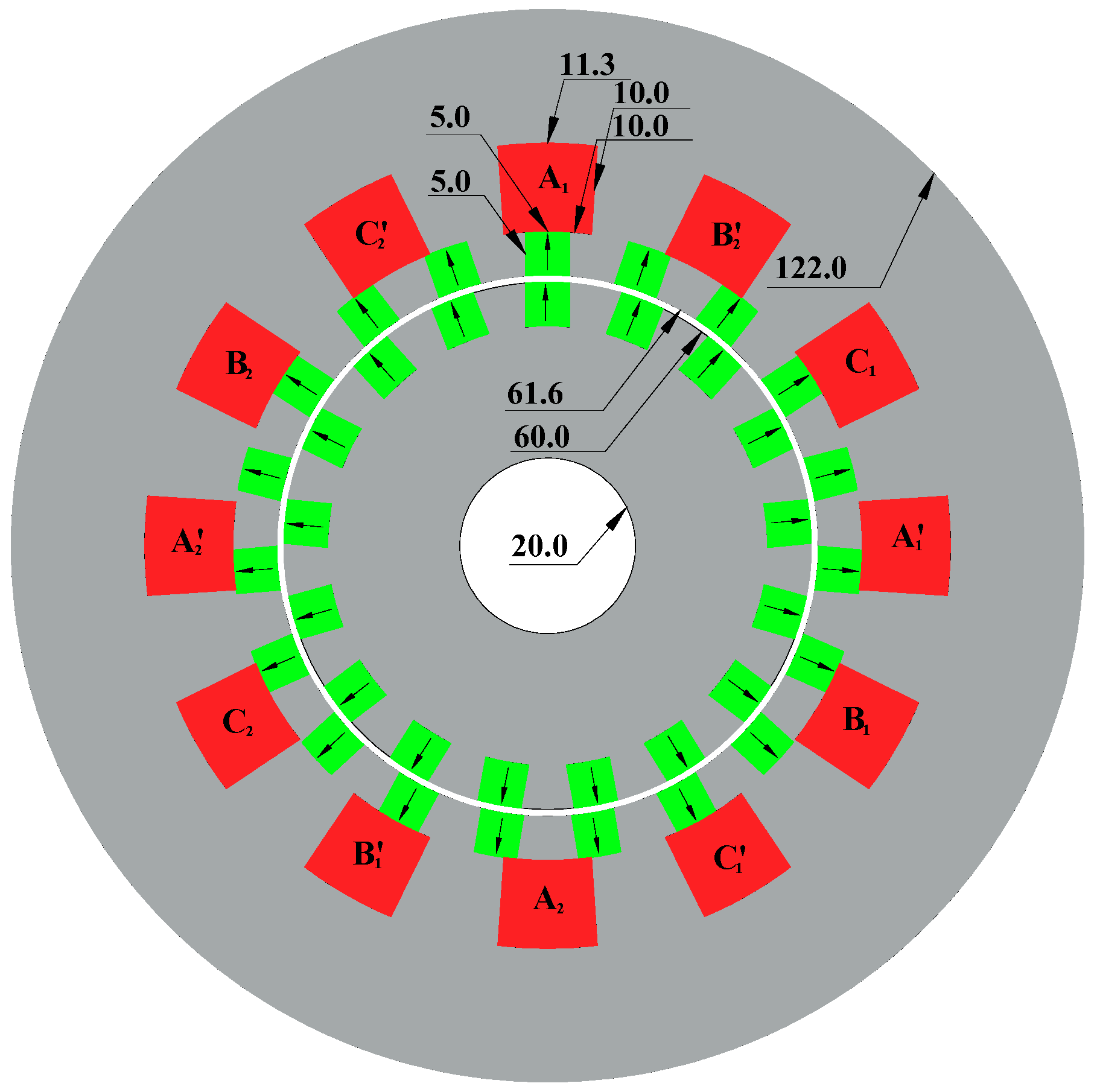
2.1. Dual-Permanent-Magnet-Excited Machine
- Double PMs: the number of rotor and stator PMs are increased by 2 times to 52 and 58 PMs, respectively. Thickness of PMs is reduced to 5 mm, air gap is 0.8 mm, and phase mark of the winding is modified to ABCABC. The other dimensions are fixed.
- Haft PMs, slots and dimensions: the number of rotor and stator PMs, rotor and stator diameter, the number of slots is reduced by 2 times. Thickness and height of the PMs are modified to 5 mm.
- Two third PMs, slots and dimensions: the number of rotor and stator PMs, rotor and stator diameter, the number of slots is reduced by 2/3. These modifications lead to final modified DPMM machine geometry with 17 rotor PMs, 19 stator PMs, 60 mm of outer diameter of rotor, 122 mm of outer diameter of stator, and 12 slots.
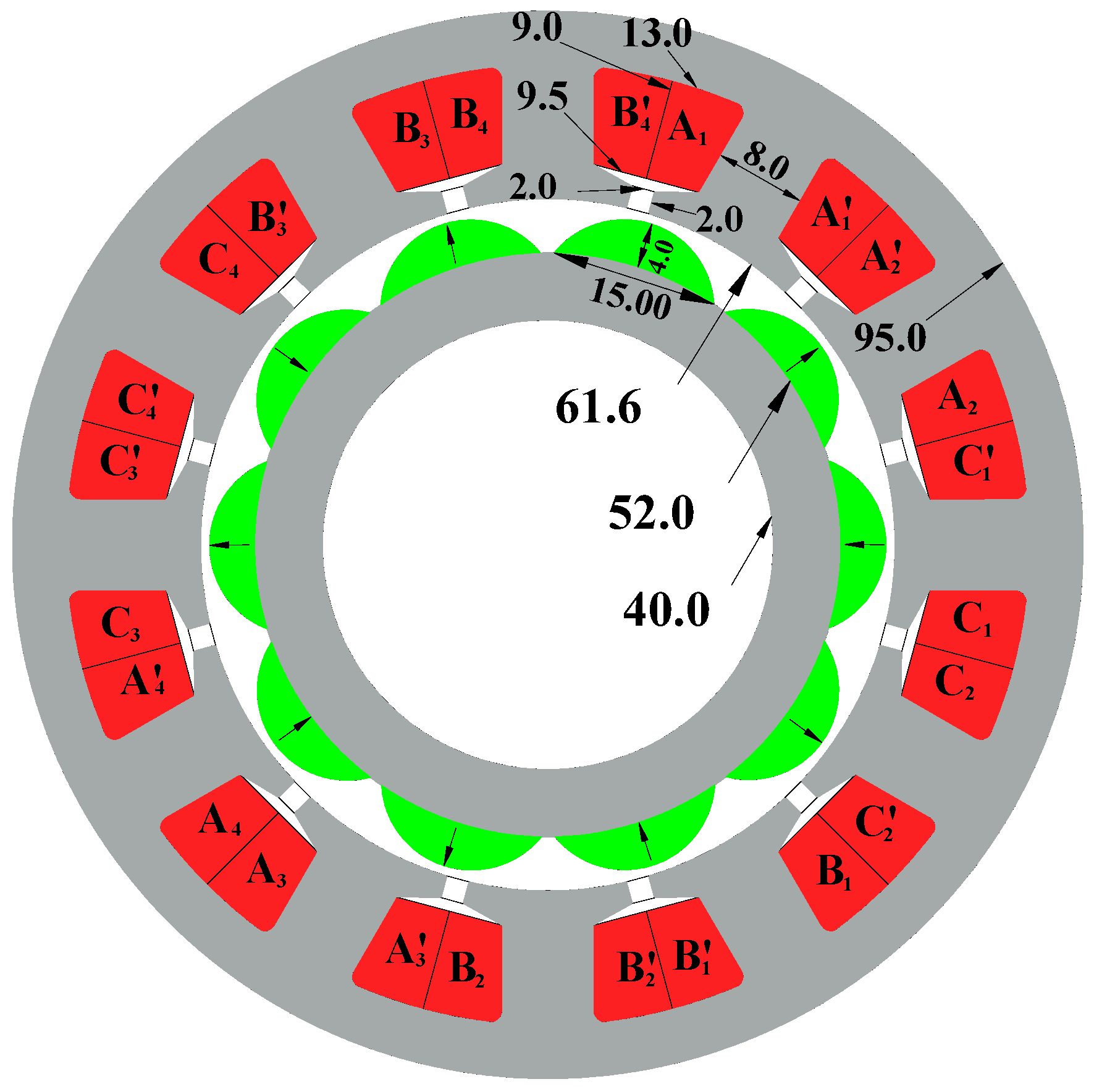
2.2. Surface-Mounted Permanent Magnet Machine
3. Optimal Design of the DPMM Machine
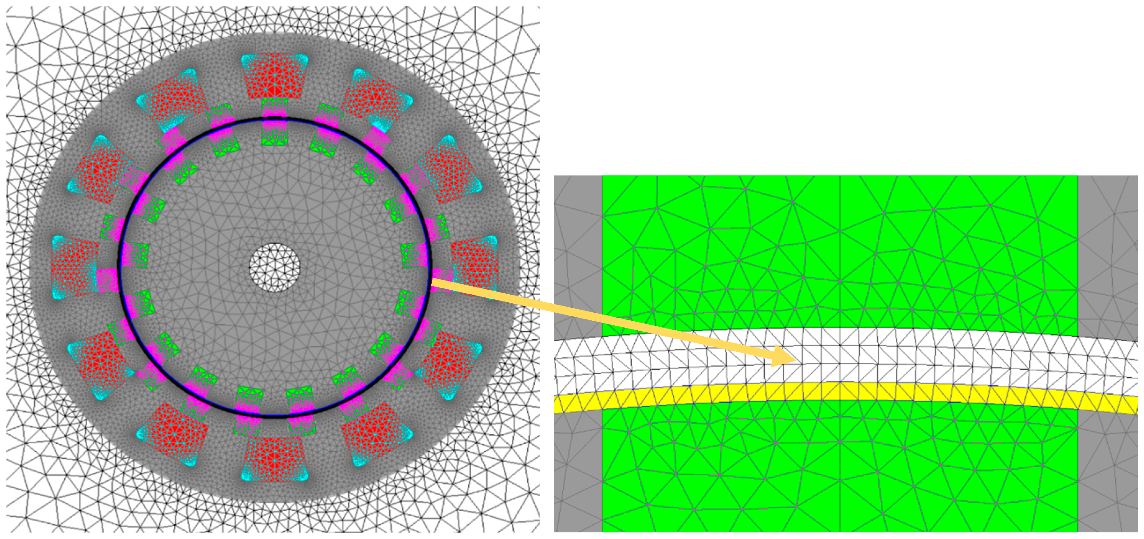
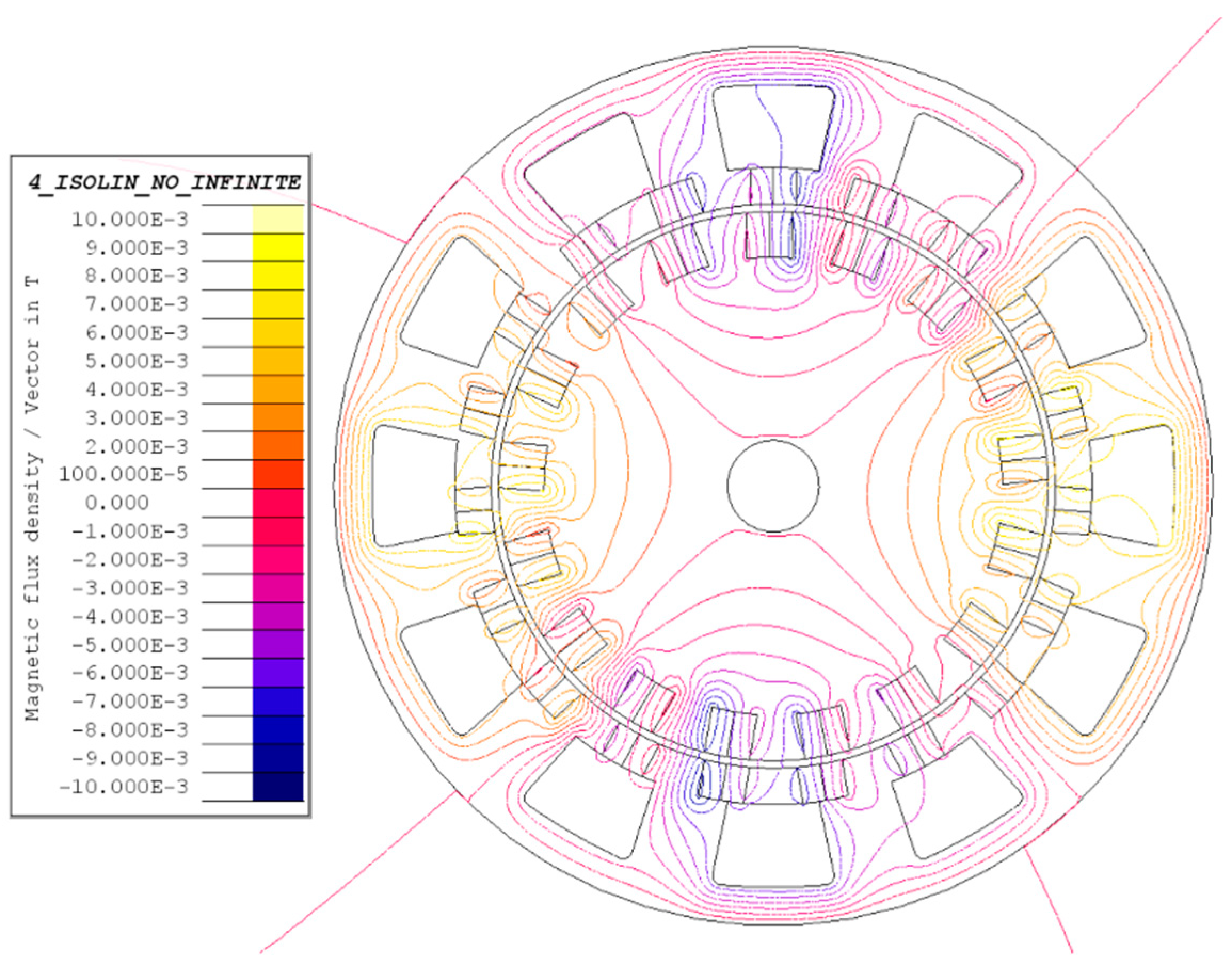
3.1. Original Design of The DPMM
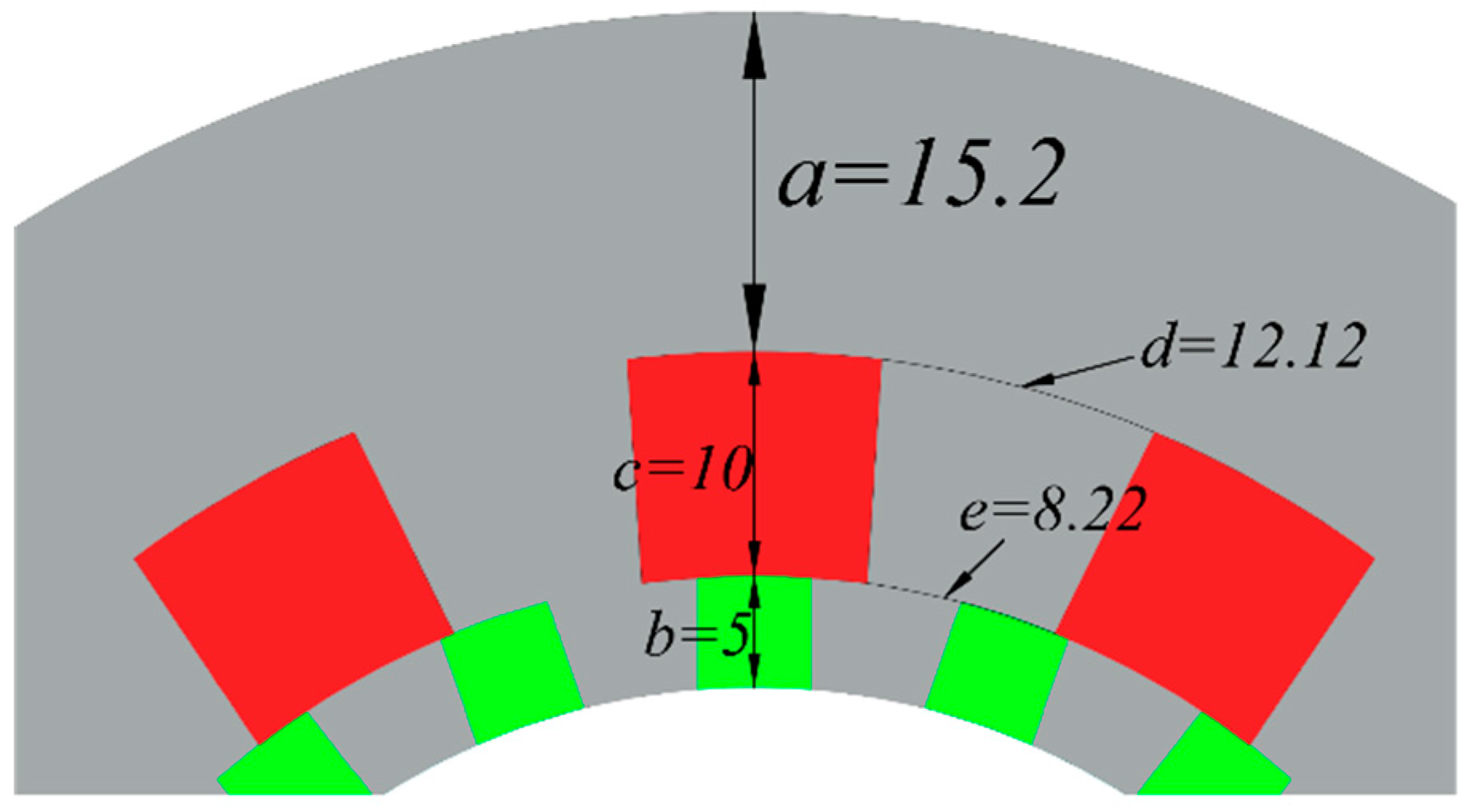
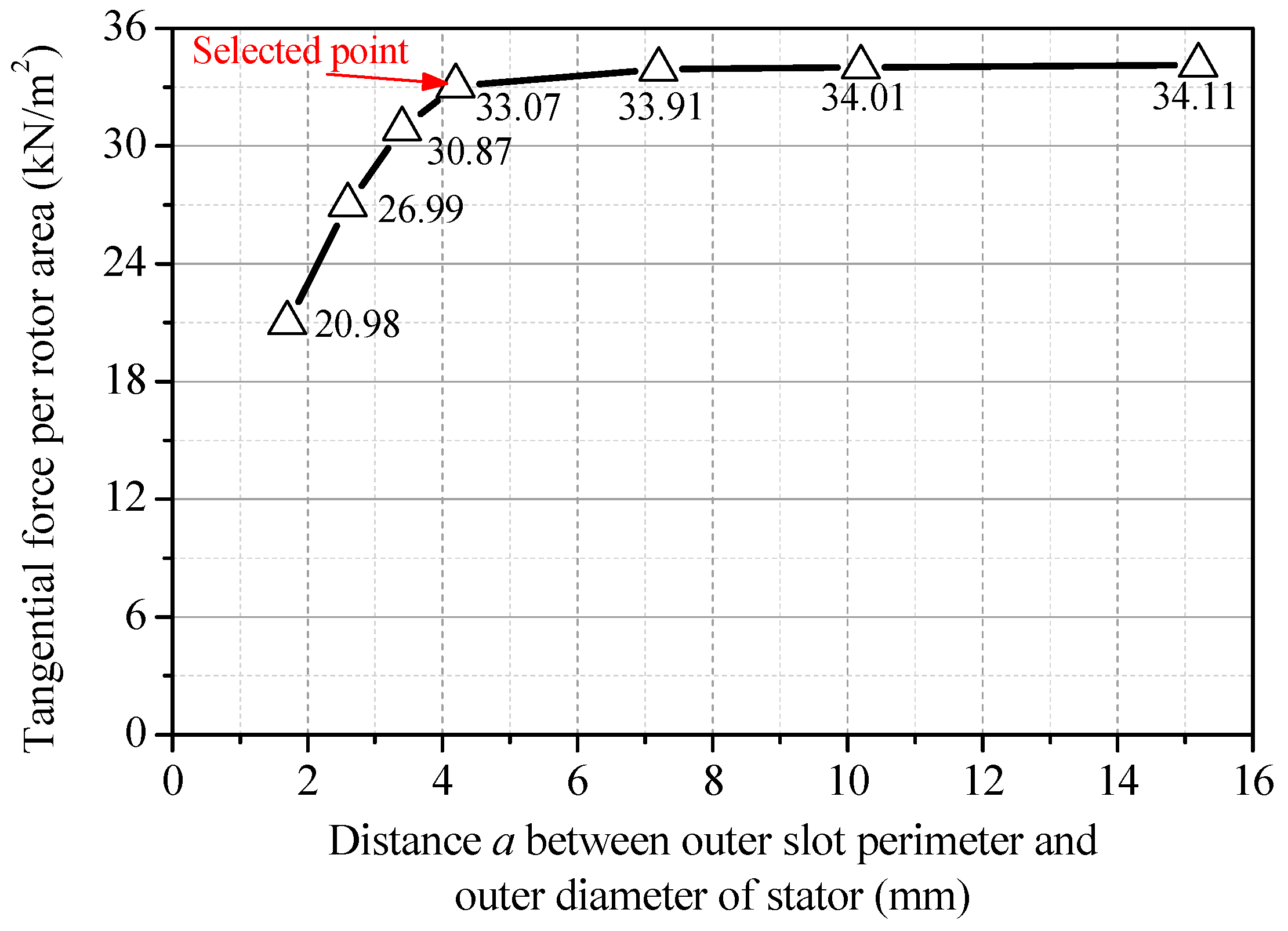
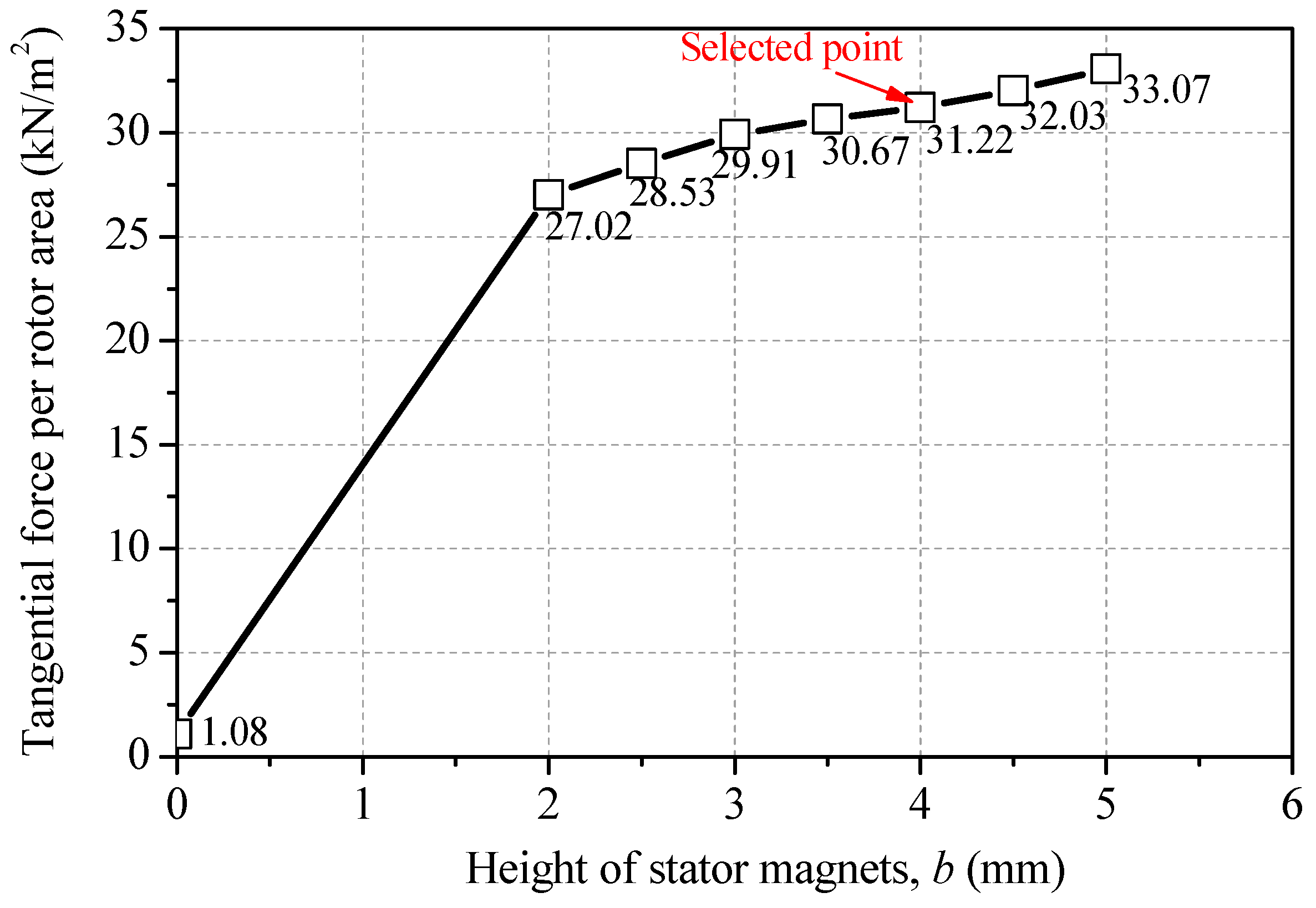
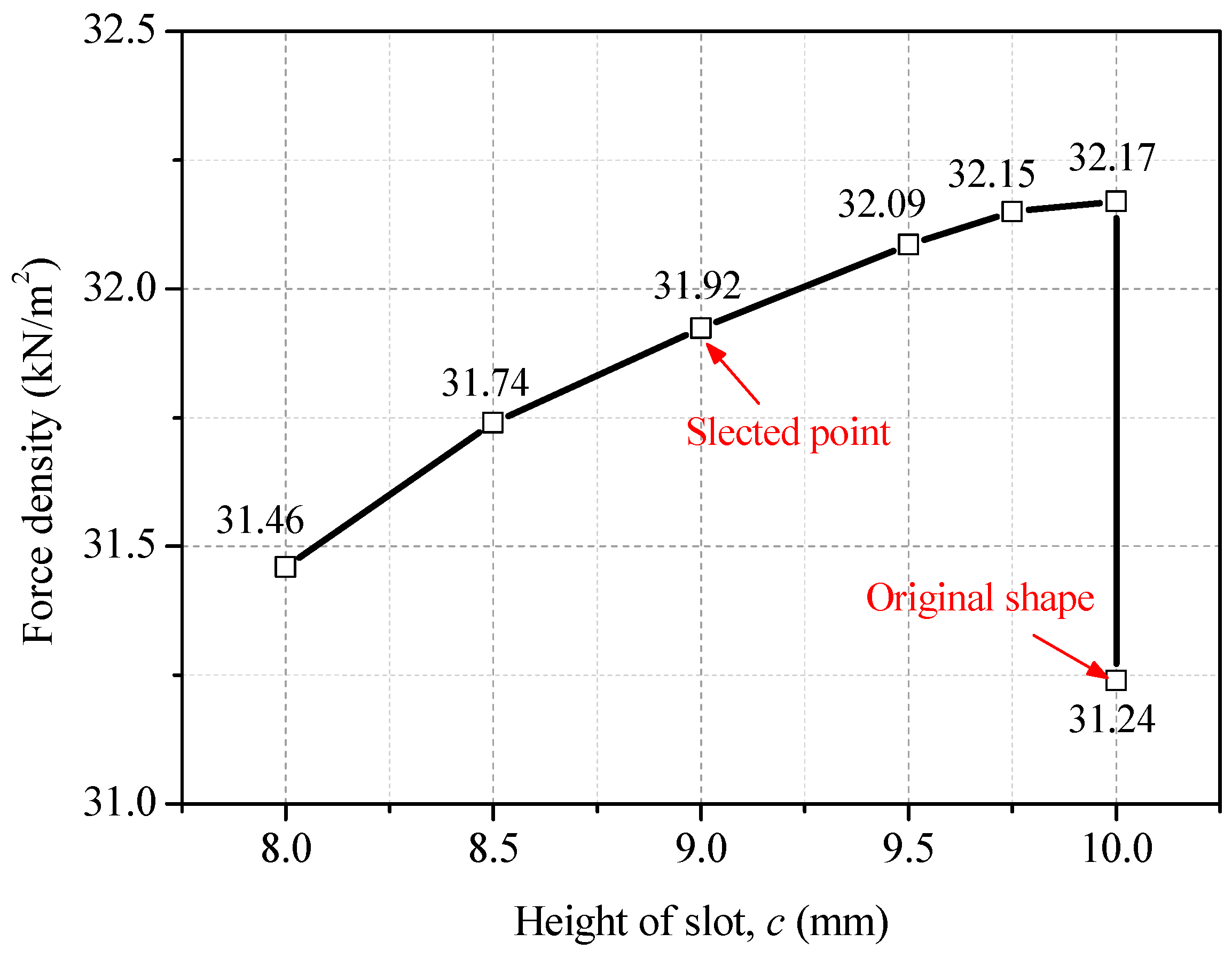
3.2. Optimal Design of the DPMM
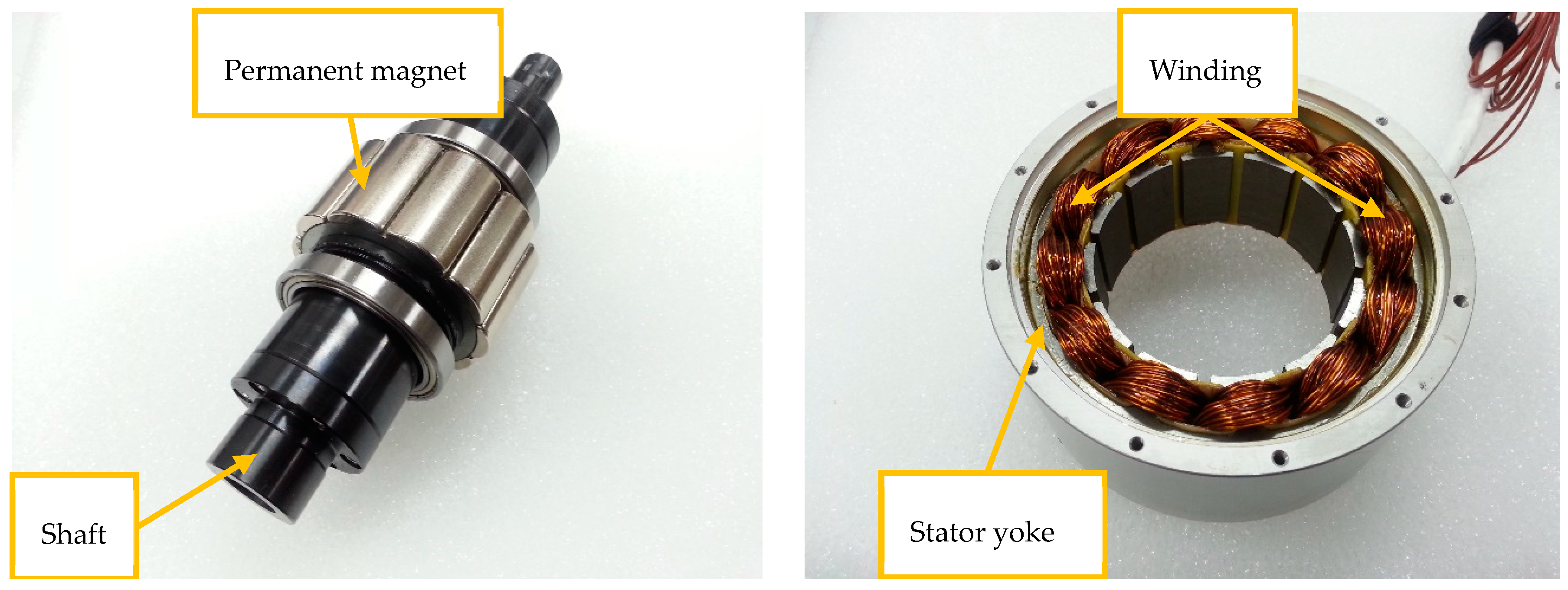
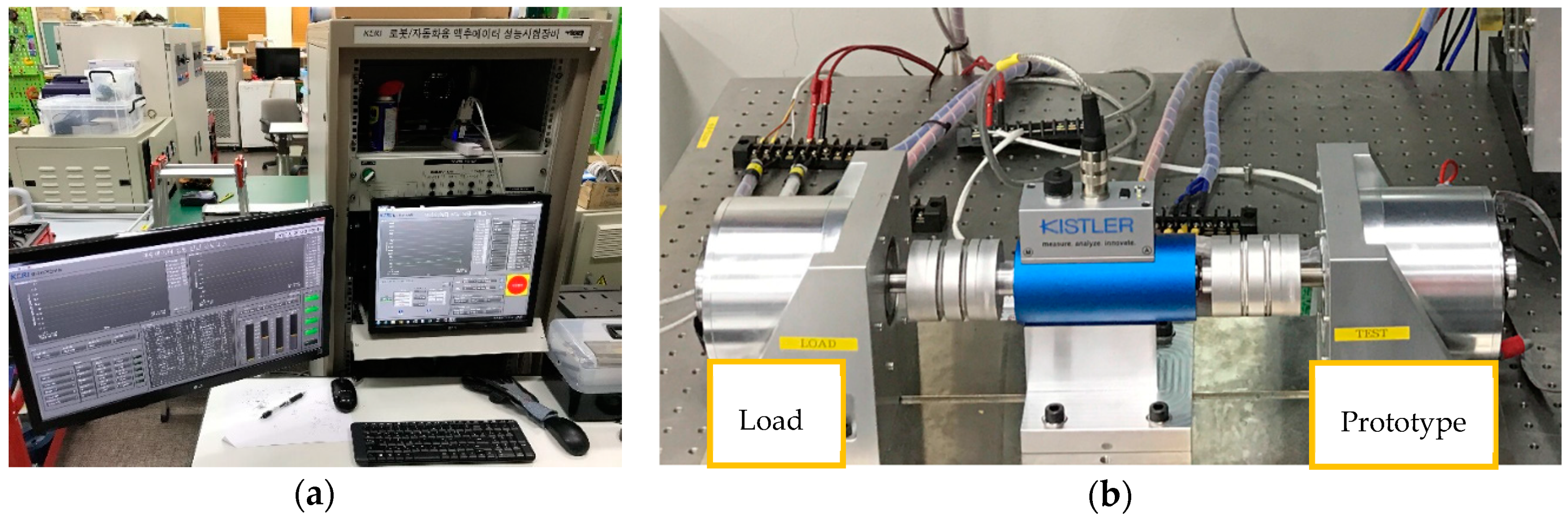
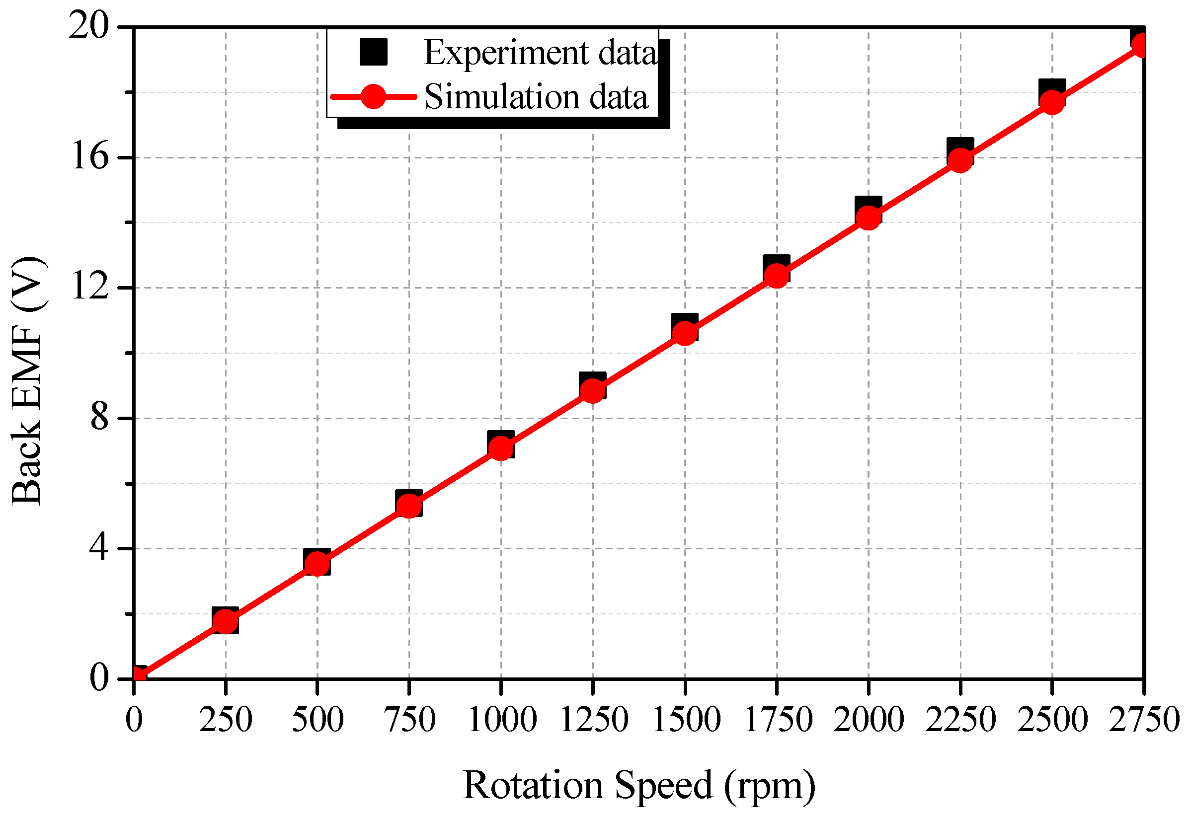
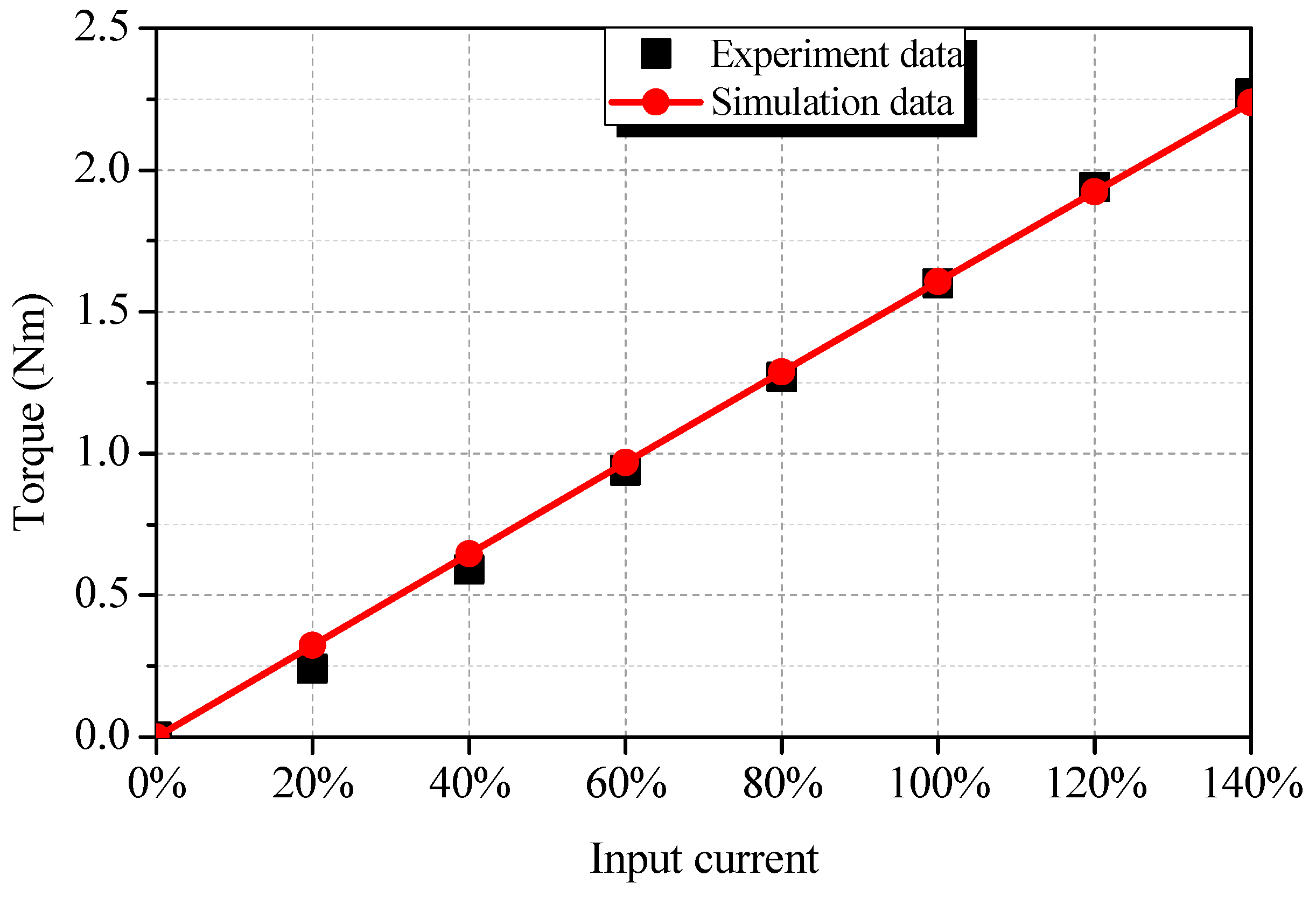
4. Validation by Experiment
5. Conclusions
Author Contributions
Funding
Conflicts of Interest
References
- Ahmad, M.; Khan, M.R.; Iqbal, A. A Doubly Fed Induction Motor as High Torque Low Speed Drive. In Proceedings of the 2006 International Conference on Power Electronic, Drives and Energy Systems, New Delhi, India, 12–15 December 2006; pp. 1–3. [Google Scholar]
- Kawamura, W.; Chen, K.; Hagiwara, M.; Akagi, H. A Low-Speed, High-Torque Motor Drive Using a Modular Multilevel Cascade Converter Based on Triple-Star Bridge Cells (MMCC-TSBC). IEEE Trans. Ind. Appl. 2015, 51, 3965–3974. [Google Scholar] [CrossRef]
- Jian, L.; Shi, Y.; Liu, C.; Xu, G.; Gong, Y.; Chan, C.C. A Novel Dual-Permanent-Magnet-Excited Machine for Low-Speed Large-Torque Applications. IEEE Trans. Magn. 2013, 49, 2381–2384. [Google Scholar] [CrossRef]
- Liu, X.; Zhong, X.; Du, Y.; Chen, X. A Novel Triple-Permanent-Magnet-Excited Vernier Machine with Double-Stator Structure for Low-Speed and High-Torque Applications. Energies 2018, 11, 1713. [Google Scholar] [CrossRef]
- Zou, T.; Li, D.; Qu, R.; Jiang, D.; Li, J. Advanced High Torque Density PM Vernier Machine With Multiple Working Harmonics. IEEE Trans. Ind. Appl. 2017, 53, 5295–5304. [Google Scholar] [CrossRef]
- Kang, D.H.; Chun, Y.H.; Weh, H. Analysis and optimal design of transverse flux linear motor with PM excitation for railway traction. IEE Proc. Electr. Power Appl. 2003, 150, 493–499. [Google Scholar] [CrossRef]
- Jian, L.; Xu, G.; Mi, C.C.; Chau, K.T.; Chan, C.C. Analytical Method for Magnetic Field Calculation in a Low-Speed Permanent-Magnet Harmonic Machine. IEEE Trans. Energy Convers. 2011, 26, 862–870. [Google Scholar] [CrossRef]
- Sato, K.; Shin, J.; Koseki, T.; Aoyama, Y. Basic experiments for high-torque, low-speed permanent magnet synchronous motor and a technique for reducing cogging torque. In Proceedings of the XIX International Conference on Electrical Machines—ICEM 2010, Rome, Italy, 6–8 September 2010; pp. 1–6. [Google Scholar]
- Mese, E.; Yasa, Y.; Ertugrul, B.T.; Sincar, E. Design of a high performance servo motor for low speed high torque application. In Proceedings of the 2014 International Conference on Electrical Machines (ICEM), Berlin, Germany, 2–5 September 2014; pp. 2014–2020. [Google Scholar]
- Vukotić, M.; Miljavec, D. Design of a permanent-magnet flux-modulated machine with a high torque density and high power factor. IET Electr. Power Appl. 2016, 10, 36–44. [Google Scholar] [CrossRef]
- Kang, D.H.; Weh, H. Design of an integrated propulsion, guidance, and levitation system by magnetically excited transverse flux linear motor (TFM-LM). IEEE Trans. Energy Convers. 2004, 19, 477–484. [Google Scholar] [CrossRef]
- Atallah, K.; Calverley, S.D.; Howe, D. Design, analysis and realisation of a high-performance magnetic gear. IEE Proc. Electr. Power Appl. 2004, 151, 135–143. [Google Scholar] [CrossRef]
- Ji, J.; Zhao, J.; Zhao, W.; Fang, Z.; Liu, G.; Du, Y. New High Force Density Tubular Permanent-Magnet Motor. IEEE Trans. Appl. Supercond. 2014, 24, 1–5. [Google Scholar] [CrossRef]
- Artetxe, G.; Paredes, J.; Prieto, B.; Martinez-Iturralde, M.; Elosegui, I. Optimal Pole Number and Winding Designs for Low Speed–High Torque Synchronous Reluctance Machines. Energies 2018, 11, 128. [Google Scholar] [CrossRef]
- Xiao-hai, L.; Zhu, L.; Ji-min, Z.; Jiang, S. Research on special low-speed, high-torque permanent magnet synchronous motor for screw pump. In Proceedings of the 2009 IEEE 6th International Power Electronics and Motion Control Conference, Wuhan, China, 17–20 May 2009; pp. 1858–1862. [Google Scholar]
- Flux 2D/3D Fast and Robust Electromagnetic, Electric and Thermal Solver. Available online: https://altairhyperworks.com/product/flux/Capabilities---Robust-Solver (accessed on 4 December 2018).
- Hoang, T.; Kang, D.; Lee, J. Comparisons Between Various Designs of Transverse Flux Linear Motor in Terms of Thrust Force and Normal Force. IEEE Trans. Magn. 2010, 46, 3795–3801. [Google Scholar] [CrossRef]
- Seite Nicht Gefunden—VACUUMSCHMELZE GmbH & Co. KG. Available online: https://www.vacuumschmelze.de/404.html (accessed on 4 December 2018).


| Configuration | Original DPMM | Equivalent DPMM |
|---|---|---|
| Stator PMs, p1 (pole) | 29 | 19 |
| Rotor PMs, p2 (pole) | 26 | 17 |
| PMs thickness (mm) | 10 | 5 |
| PMs height (mm) | 10 | 5 |
| Inner diameter of rotor, Dri (mm) | 120 | 20 |
| Outer diameter of rotor, Dro (mm) | 178 | 60 |
| Inner diameter of stator, Dsi (mm) | 179.2 | 61.6 |
| Outer diameter of stator, Dso (mm) | 269.8 | 122 |
| Airgap, g (mm) | 0.6 | 0.8 |
| Number of slots, Ns | 36 | 12 |
| Number of poles, p | 6 | 4 |
| Winding pattern | AABBCC | ABCABC |
| Items | DPMM | SPM |
|---|---|---|
| Stacking length, Lst (mm) | 90 | |
| Outer diameter of rotor, Dro (mm) | 60 | |
| Outer diameter of stator, Dso (mm) | 122 | 95 |
| Air gap, g (mm) | 0.8 | |
| Electrical steel sheet | 35PN380 | |
| Permanent magnet material | NdFeB − Br = 1.2T; µr = 1.05 at 20 °C | |
| Copper fill factor, kfill | 50% | |
| Total current ampere-turn (100%) (rms current per slot * number of slot) | 6120AT (510 × 12) | |
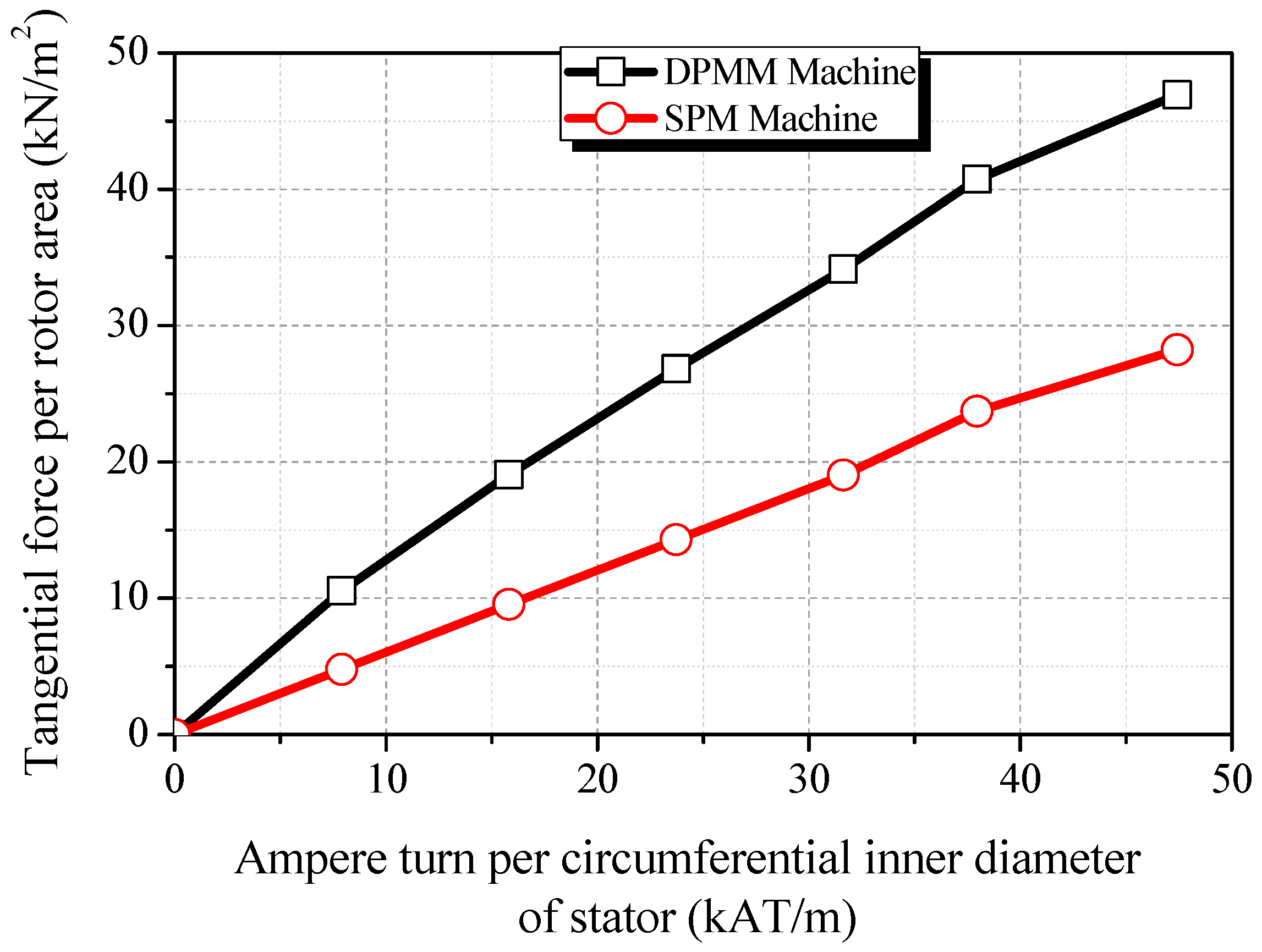
| Current (AT) | Output Torque (Nm) | Tangential Force Per Rotor Area (kN/m2) | ||
|---|---|---|---|---|
| DPMM | SPM | DPMM | SPM | |
| 0 (0%) | 0.00 | 0.00 | 0.00 | 0.00 |
| 1530 (25%) | 5.37 | 2.43 | 10.55 | 4.77 |
| 3060 (50%) | 9.70 | 4.86 | 19.06 | 9.55 |
| 4590 (75%) | 13.66 | 7.28 | 26.84 | 14.30 |
| 6120 (100%) | 17.36 | 9.69 | 34.11 | 19.04 |
| 7650 (125%) | 20.72 | 12.06 | 40.71 | 23.70 |
| 9180 (150%) | 23.87 | 14.36 | 46.90 | 28.22 |
| Parameters | Optimal DPMM | SPM |
|---|---|---|
| Inner diameter of rotor, Dri (mm) | 20 | 40 |
| Outer diameter of rotor, Dri (mm) | 60 | |
| Inner diameter of stator, Dsi (mm) | 61.6 | |
| Outer diameter of stator, Dso (mm) | 100 | 95 |
| Air gap, g (mm) | 0.8 | |
| Total current ampere-turn (100%) | 6120 | |
| Copper fill factor, kfill (%) | 50 | |
| Number of slot, Ns | 12 | |
| Electrical steel sheet | 35PN380 | |
| Permanent magnet | NdFeB − Br = 1.2T; µr = 1.05 at 20 °C | |
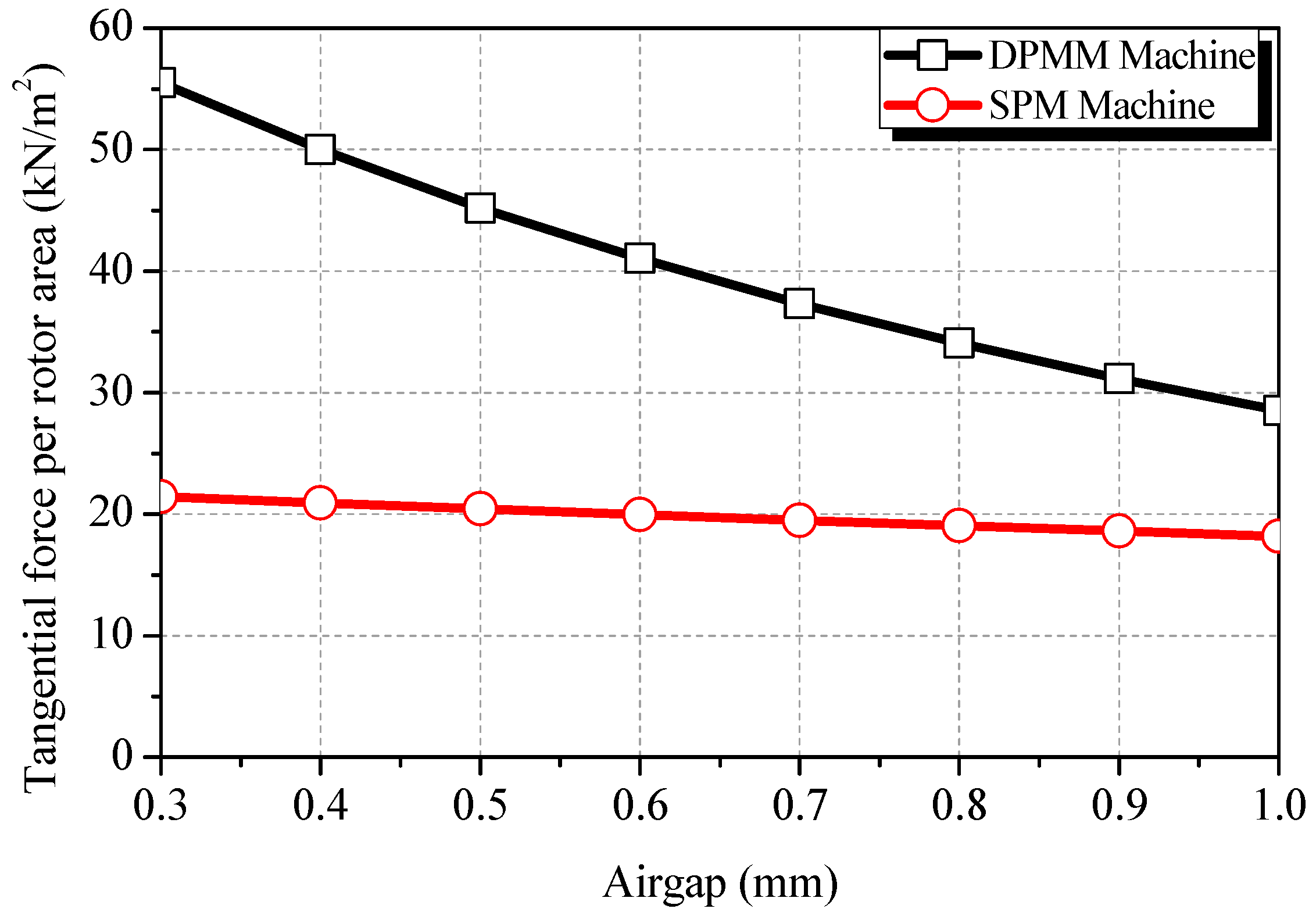
| Tangential force density, (kN/m2) (at 100% current ampere turn) | 31.92 | 19.04 |
| Torque/volume, (kN/m3) (rotor torque per motor total volume) | 45.16 | 29.85 |
| Iron losses (W) | 101.91 | 15.84 |
| Power factor | 0.62 | 0.95 |
| Items | Compared SPM | Commercial SPM |
|---|---|---|
| Staking length, Lst (mm) | 90 | 31 |
| Outer diameter of rotor, Dri (mm) | 60 | 63.5 |
| Inner diameter of stator, Dsi (mm) | 61.6 | 66 |
| Outer diameter of stator, Dso (mm) | 95 | 100 |
| Air gap, g (mm) | 0.8 | 1.25 |
| Number of turns/slot | 1 | 15 |
© 2019 by the authors. Licensee MDPI, Basel, Switzerland. This article is an open access article distributed under the terms and conditions of the Creative Commons Attribution (CC BY) license (http://creativecommons.org/licenses/by/4.0/).
Share and Cite
Duong, M.-T.; Kang, D.-H.; Chun, Y.-D.; Woo, B.-C.; Lee, Y.-S.; Wook, H. Comparison of Dual-Permanent-Magnet-Excited Machines and Surface-Mounted Permanent Magnet Machines in Terms of Force. Energies 2019, 12, 216. https://doi.org/10.3390/en12020216
Duong M-T, Kang D-H, Chun Y-D, Woo B-C, Lee Y-S, Wook H. Comparison of Dual-Permanent-Magnet-Excited Machines and Surface-Mounted Permanent Magnet Machines in Terms of Force. Energies. 2019; 12(2):216. https://doi.org/10.3390/en12020216
Chicago/Turabian StyleDuong, Minh-Trung, Do-Hyun Kang, Yon-Do Chun, Byung-Chul Woo, Yoon-Sun Lee, and Hwang Wook. 2019. "Comparison of Dual-Permanent-Magnet-Excited Machines and Surface-Mounted Permanent Magnet Machines in Terms of Force" Energies 12, no. 2: 216. https://doi.org/10.3390/en12020216
APA StyleDuong, M.-T., Kang, D.-H., Chun, Y.-D., Woo, B.-C., Lee, Y.-S., & Wook, H. (2019). Comparison of Dual-Permanent-Magnet-Excited Machines and Surface-Mounted Permanent Magnet Machines in Terms of Force. Energies, 12(2), 216. https://doi.org/10.3390/en12020216