Article

Sequential Model Predictive Control of Three-Phase Direct Matrix Converter

1
Faculty of Engineering and IT, University of Technology Sydney, Broadway NSW 2007, Sydney, Australia
2
College of Electric Power, Inner Mongolia University of Technology, Hohhot 010000, China
3
Departamento de Ing. Electrica, Universidad Tecnica Federico Santa Maria, Valparaiso 2390123, Chile
4
Department of Electrical Engineering, University of KwaZulu-Natal, Durban 4001, South Africa
5
Facultad de Ingenieria, Universidad Andres Bello, Santiago 7500791, Chile
*
Author to whom correspondence should be addressed.
Energies 2019, 12(2), 214; https://doi.org/10.3390/en12020214
Submission received: 21 November 2018 / Revised: 28 December 2018 / Accepted: 6 January 2019 / Published: 10 January 2019
(This article belongs to the Special Issue Control in Power Electronics)

Abstract

:
The matrix converter (MC) is a promising converter that performs the direct AC-to-AC conversion. Model predictive control (MPC) is a simple and powerful tool for power electronic converters, including the MC. However, weighting factor design and heavy computational burden impose significant challenges for this control strategy. This paper investigates the generalized sequential MPC (SMPC) for a three-phase direct MC. In this control strategy, each control objective has an individual cost function and these cost functions are evaluated sequentially based on priority. The complex weighting factor design process is not required. Compared with the standard MPC, the computation burden is reduced because only the pre-selected switch states are evaluated in the second and subsequent sequential cost functions. In addition, the prediction model computation for the following cost functions is also reduced. Specifying the priority for control objectives can be achieved. A comparative study with traditional MPC is carried out both in simulation and an experiment. Comparable control performance to the traditional MPC is achieved. This controller is suitable for the MC because of the reduced computational burden. Simulation and experimental results verify the effectiveness of the proposed strategy.

1. Introduction

The direct matrix converter (MC) carries out direct AC-to-AC power conversion, and it does not require any bulky energy storage elements. This converter provides many benefits, including bidirectional power flow, controllable input power factor, compact volume, and higher power density [1,2,3,4]. Therefore, MCs attract tremendous research interest and are proposed for many application areas. Some manufacturers, such as Yaskawa and Fuji, have commercialized some MC products and modules. Table 1 summarizes some information of some MC products that are commercialized in the industry. As seen in this Table, the maximum voltage and power ratings reach 6.6 kV and 6 MVA in Yaskawa MX1S series. The main application area is oriented to industrial motor drives.
In academia, many control techniques have been researched for MCs [5,6]. These mainly include the Venturini method [7,8], space vector modulation [9,10], direct torque control [11,12], hysteresis control [13,14], and model predictive control (MPC) [15,16,17,18]. The performance comparison of these control techniques is summarized in Table 2. Among these controllers, MPC has emerged as a popular and promising control alternative in power converters and drives because of its simplicity, flexibility in system constraint integration, and potential to be applied in a wide range of areas.
The situation is aggravated if more control objectives are included or more switch states need to be evaluated.
MPC explicitly incorporates control objectives and system constraints in a cost function. All allowable switch states of a converter are evaluated in this cost function to optimize the selection of switch states. The higher number of switch states contributes to the heavier computational burden. MPC was investigated for most power electronic converters [19,20,21,22]. However, there are some drawbacks associated with MPC, including a complicated weighting factor design and heavy computational burden.
The weighting factor is usually obtained using empirical methods via a trial-and-error process, which is time-consuming. Some research efforts have been devoted to addressing the weighting factor issues. In [23], guidelines for designing weighting factors for power converters were presented. Empirical processes are still involved. A multi-objective ranking-based MPC was proposed to regulate the torque and flux of an induction motor in [24]. Weighting factor design was avoided; however, all control objectives were treated as equal, compromising the control. In addition, all switch states were evaluated in each cost function, resulting in a heavy computational burden. Many other methods for avoiding weighting factors either require conversion of the regulated variables into equivalent quantities or involves another technique [25,26,27]. These are undesirable because the control system complexity is increased. When control complexity is increased, the computational burden is also increased. Heavy computation burden is one of factors hindering the wide application of MPC [21]. Therefore, it is beneficial to reduce the computational burden.
As a possible solution, this paper investigates a sequential MPC (SMPC) for a three-phase direct MC. In this control strategy, the complex weighting factor design process is avoided, and thus the computational burden is reduced. SMPC was first proposed in [22] for an induction motor. Only two control objectives were considered and the controller was not generalized. In this work, the control strategy was extended to the matrix converter and generalized for controlling n variables. The contributions of this paper include: (i) A generalized SMPC strategy is proposed and this method is investigated for a three-phase direct MC. The regulation of different control objectives can be achieved, avoiding the sophisticated design of weighting factors. (ii) With the proposed control strategy, the cost functions corresponding to control objectives are evaluated individually and sequentially. In this way, the computational burden is reduced since only the pre-selected switch states are evaluated in the subsequent cost functions. (iii) Priority of control objectives can be specified with the proposed strategy. A comparative study is carried out to compare the performance of the proposed controller with the conventional MPC. A similar performance can be achieved, while the reduced computational burden enables further improvement of the performance in the proposed strategy. The proposed controller is suitable for the MC, especially when there are several control objectives because the computational burden can be reduced. Both simulation and experimental results are presented to verify the proposed SMPC.

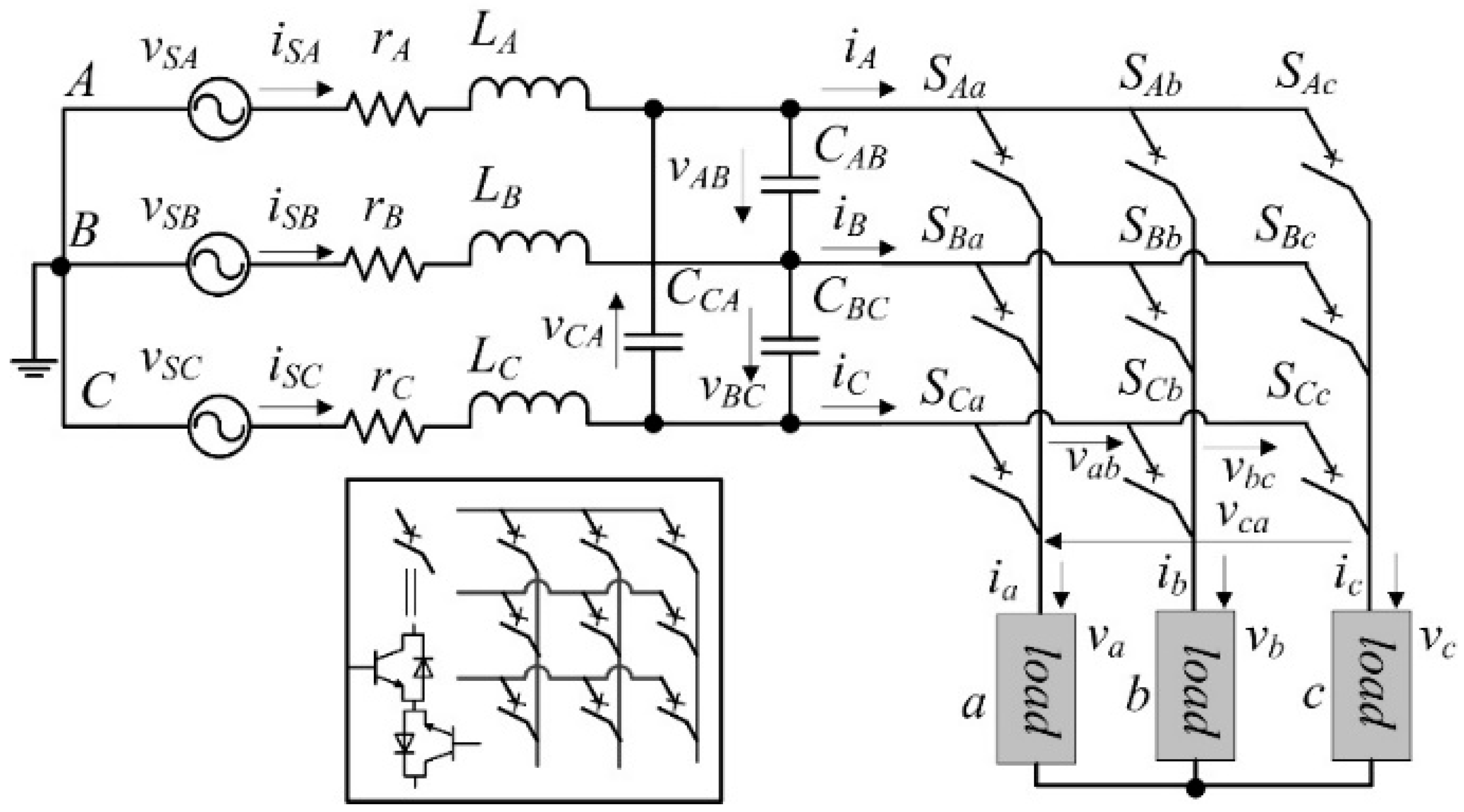
2. Prediction Models of the Matrix Converter and Load

There are nine bidirectional semiconductor switches in a three-phase direct MC, as shown in Figure 1. These nine switches compose 27 allowable switch states that need to be evaluated in the cost function of the MPC, which can lead to the heavy computational burden.
The semiconductor switches in an MC are arranged in the form of a 3 × 3 matrix. The relationship between the inputs and outputs of the MC can be established as:
[ v a v b v c ] = [ S A a S B a S C a S A b S B b S C b S A c S B c S C c ] [ v A v B v C ] = S [ v A v B v C ]
[ i A i B i C ] = [ S A a S A b S A c S B a S B b S B c S C a S C b S C c ] [ i a i b i c ] = S T [ i a i b i c ]
X = A , B , C S X x = 1 , ( x = a , b , c )
where S (transpose ST) is the switch matrix and vA,B,C are the output phase voltages. Other variables are denoted in Figure 1. The elements, SXx, in the switch matrix can be assigned a value of 1 for the ON state and 0 for the OFF state. As a result, there are 29 = 512 switch combinations in total in a three-phase direct MC. Based on the measurement of vA,B,C and ia,b,c, the voltages and currents, va,b,c and iA,B,C, can be calculated respectively, which will be used in the prediction models. The constraint (3) is used to exclude the invalid switch states that can cause detrimental overvoltage and overcurrent.
In MPC, system models are employed to predict the targeted variables. To regulate the MC output current, an output model needs to be developed. For an inductive-resistive load, (Ra, La), the output model can be represented as:
{ v a = i a R a + L a d i a d t v b = i b R b + L b d i b d t v c = i c R c + L c d i c d t
Here, the variables are defined in Figure 1. Due to the symmetry of the three-phase system, it is sufficient to consider a single-phase model. Using the Euler method, the discretized model for the output phase, a, is obtained:
i a [ k + 1 ] = i a [ k ] R a T s L a i a [ k ] + T s L a v a [ k ]
Here, Ts is the sampling time. The discretized model in Equation (5) is used to predict future behavior of the load current, ia. ia[k], is measured using a current sensor and va[k] is calculated using Equation (1). Another control objective considered in this work is the input power factor. For this control objective, the input filter is modeled as:
{ v S A i S A R A L A d i S A d t = v A v S B i S B R B L B d i S B d t = v B v S C i S C R C L C d i S C d t = v C
{ i S A = C A d v A d t + i A i S B = C B d v B d t + i B i S C = C C d v C d t + i C
Here, CA represents the equivalent capacitance of CAB in the star connection. Similarly, it is sufficient to consider a single-phase mode for discretization.
Using the Euler method, the prediction model is obtained:
i S A [ k + 1 ] = ( 1 R A T s L A ) i S A [ k ] + T s L A v S A [ k ] T s L A v A [ k ]
On the right-hand side of Equation (8), iSA, vSA, and vA are not related to va,b c or iA,B,C in Equations (1) and (2), which means the prediction, iSA[k + 1], is independent of the switch states. Therefore, this prediction model Equation (8) cannot be straightforwardly used, and it is not suitable for MPC. Instead, the zero-order-hold method is used.
From Equations (6) and (7), the discretized input filter model can be developed in the state-space as follows:
[ i ˙ S A v ˙ A ] = F [ i S A v A ] + G [ v S A i A ] ,   F = [ R A / L A 1 / L A 1 / C A 0 ] ,   G = [ 1 / L A 0 0 1 / C A ]
[ i S A [ k + 1 ] v A [ k + 1 ] ] = A [ i S A [ k ] v A [ k ] ] + B [ v S A [ k ] i A [ k ] ] ,   A = e F T s ,   B = 0 T s e F τ d τ G
A = [ A 11 A 12 A 21 A 22 ] ,   A 11 = a e a T s b e b T s a b ,   A 12 = ( e a T s e b T s ) L o a ( a b ) ,   A 21 = e a T s e b T s C a b ( a b ) ,   A 22 = a e a T s b e b T s a b + R o a ( e a T s e b T s ) L o a ( a b )
B = [ B 11 B 12 B 21 B 22 ] ,   B 11 = e a T s e b T s L o a ( a b ) , B 12 = [ a ( e b T s 1 ) b ( e a T s 1 ) ] ( L o a C o a a b ) ( a b ) ,   B 22 = e a T s + e b T s + R o a [ a b a e b T s + b e a T s ] ( L o a C o a a b ) ( a b )
with a , b = R A / L A ± ( R A / L A ) 2 4 / C A / L A 2 . Therefore, the discretized model to predict iSA is:
i S A [ k + 1 ] = A 11 i S A [ k ] + A 12 v A [ k ] + B 11 v S A [ k ] + B 12 i A [ k ]
Here, iSA[k], vSA[k], and vA[k] are measured using sensors, while iA[k] is calculated using Equation (2). To compute the input reactive power, the three-phase variables are converted into α-β-γ components using:
[ i α i β i γ ] = 2 3 [ 1 1 / 2 1 / 2 0 3 / 2 3 / 2 1 / 2 1 / 2 1 / 2 ] [ i a i b i c ]
[ i a i b i c ] = [ 1 0 1 1 / 2 3 / 2 1 1 / 2 3 / 2 1 ] [ i α i β i γ ]
where ia,b,c are the three-phase currents in the abc system and iα,β,γ are the currents in the αβγ system. The input reactive power is computed from:
Q [ k + 1 ] = 3 2 ( v S A β [ k + 1 ] i S A α [ k + 1 ] v S A α [ k + 1 ] i S A β [ k + 1 ] )
The supply voltage is considered stable and it barely changes during a short sampling cycle. Therefore, vSA−α,β [k + 1] = vSA−α,β [k] holds.

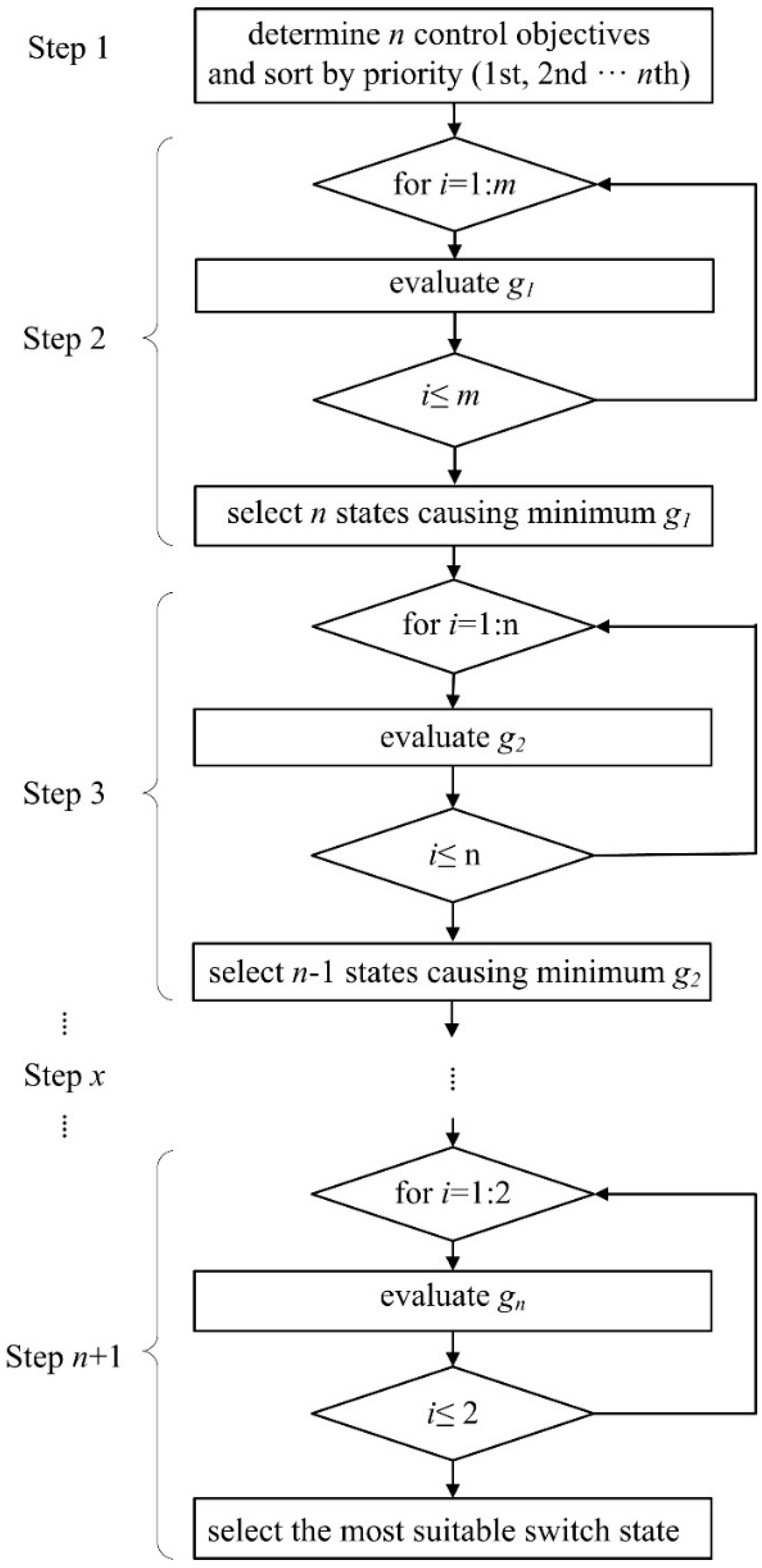
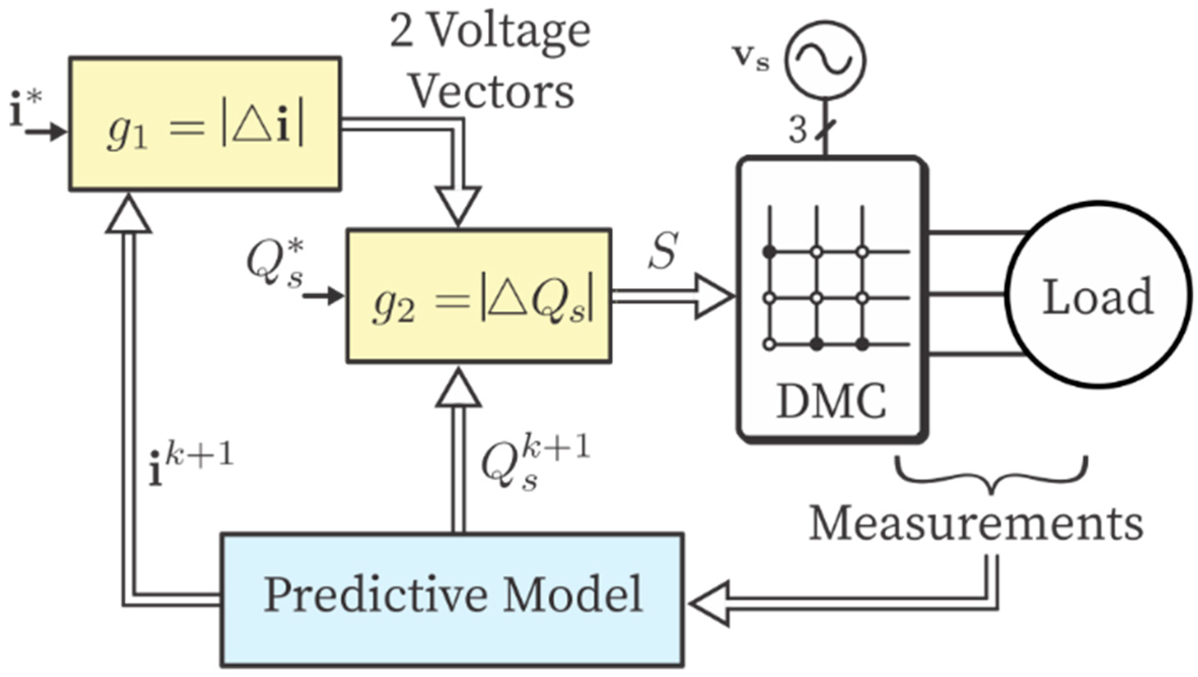
3. Systematic Descriptions of SMPC

The systematic diagram of the proposed SMPC is illustrated in Figure 2. As shown in the diagram, the proposed SMPC can be carried out in the following steps.
Step 1: Determine n control objectives or variables that need to be regulated. Sort these control objectives in terms of priority (from high to low: 1st, 2nd, …, nth). Define an individual cost function (g1 to gn) for each control objective. These cost functions enable switch state selection for controlling corresponding variables. These cost functions will be evaluated in sequential order as explained below.
Step 2: Evaluate all m available switch states (switch actions) and select n most suitable switch states that render the minimum values of g1 for regulating the first control objective.
Step 3: Evaluate the n switch states selected in the previous step and select n − 1 most suitable switch states that render the minimum values of g2 for regulating the second control objective.
Step x: Evaluate the nx + 3 switch states selected in the previous step and select nx + 2 most suitable switch states that render the minimum values of g3 for regulating the (x − 1)th control objective.
Step n + 1: Evaluate the two switch states selected in the previous step and select the most suitable switch states that render the minimum values of gn for regulating the nth control objective. The selection in this step is final and will be applied to the converter.
In the proposed SMPC, the priority determines the importance of each objective in the controller. The higher the priority, the more important it is. Generally, the priority of each control objective is determined on the specific applications and desired performance.
In this work, there are two control objectives (n = 2), i.e., the load currents and input power factor considered in SMPC for MC. The main control objective is the regulation of the load currents, so it has the highest priority. There are 27 (m = 27) allowable switch states in total in the MC. The cost functions for optimizing the selection of switch states for load currents and the input power factor are individually defined in:
g 1 = | i a * i a [ k + 1 ] | + | i b * i b [ k + 1 ] | + | i c * i c [ k + 1 ] |
g 2 = | Q * Q [ k + 1 ] |
Here, no weighting factors need to be designed for the proposed SMPC. However, in the traditional MPC, the cost function is:
g = g 1 + λ g 2
where λ is the weighting factor, which is usually obtained by time-consuming empirical methods through a complex process. The weighting factor specifies the relative importance of the control objective in traditional MPC methods.

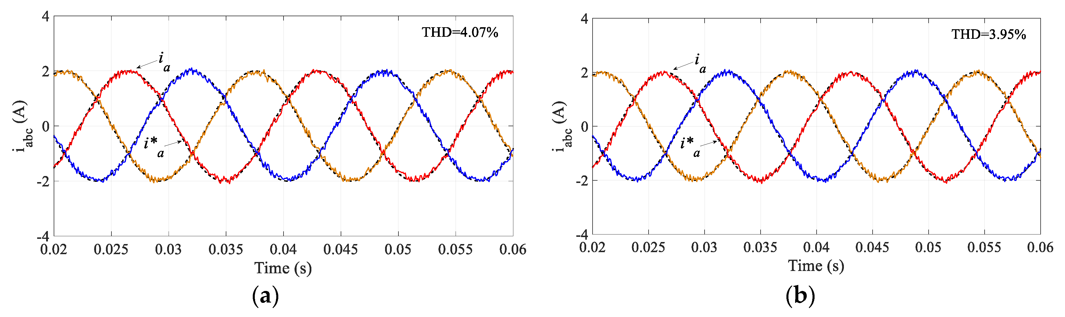
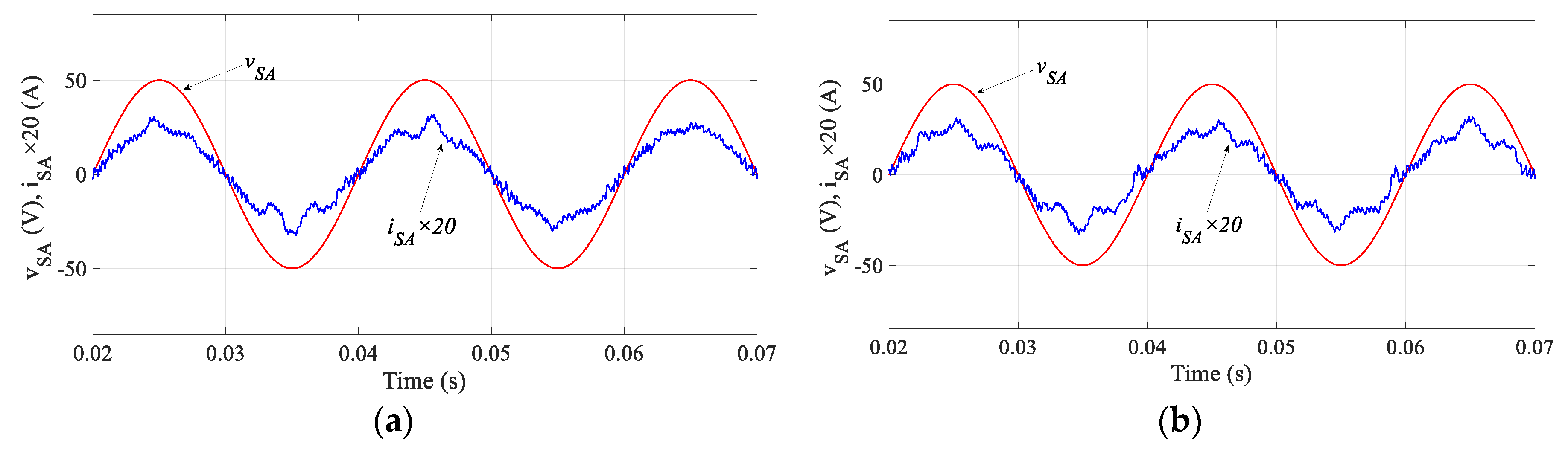
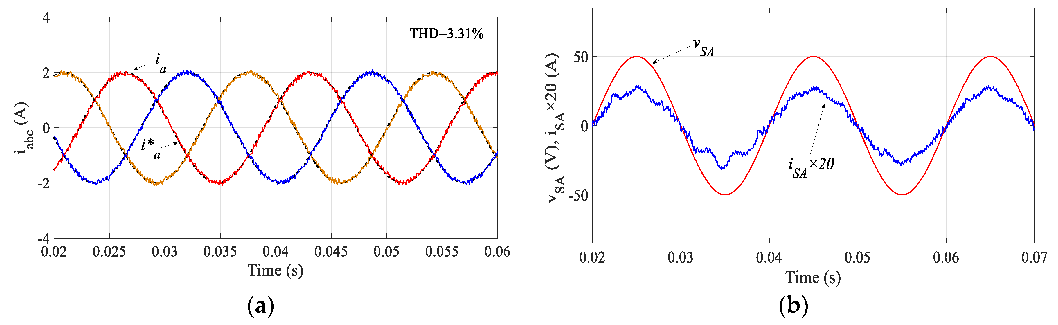
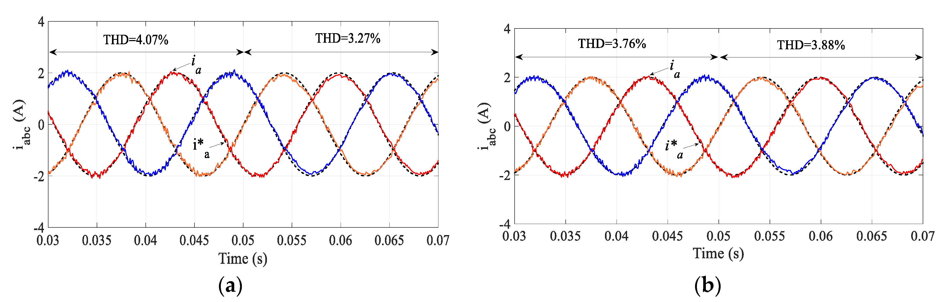
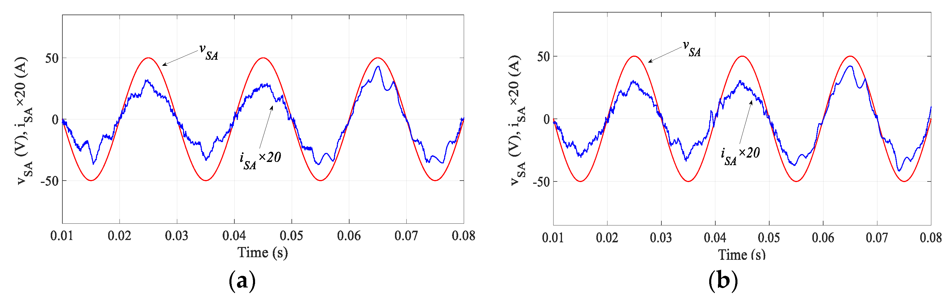
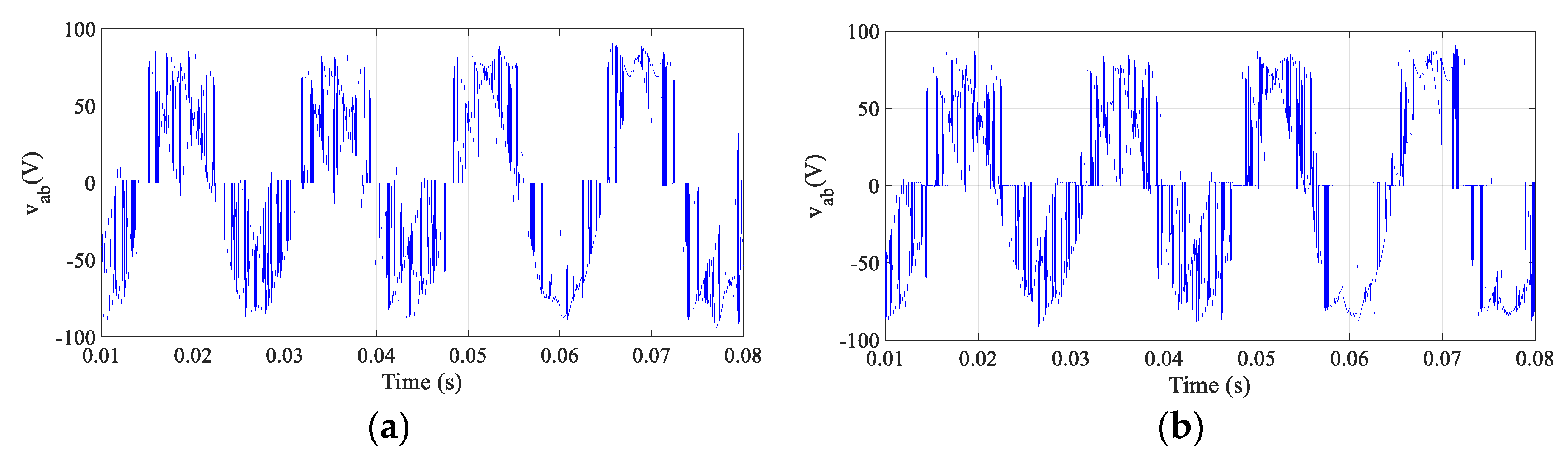
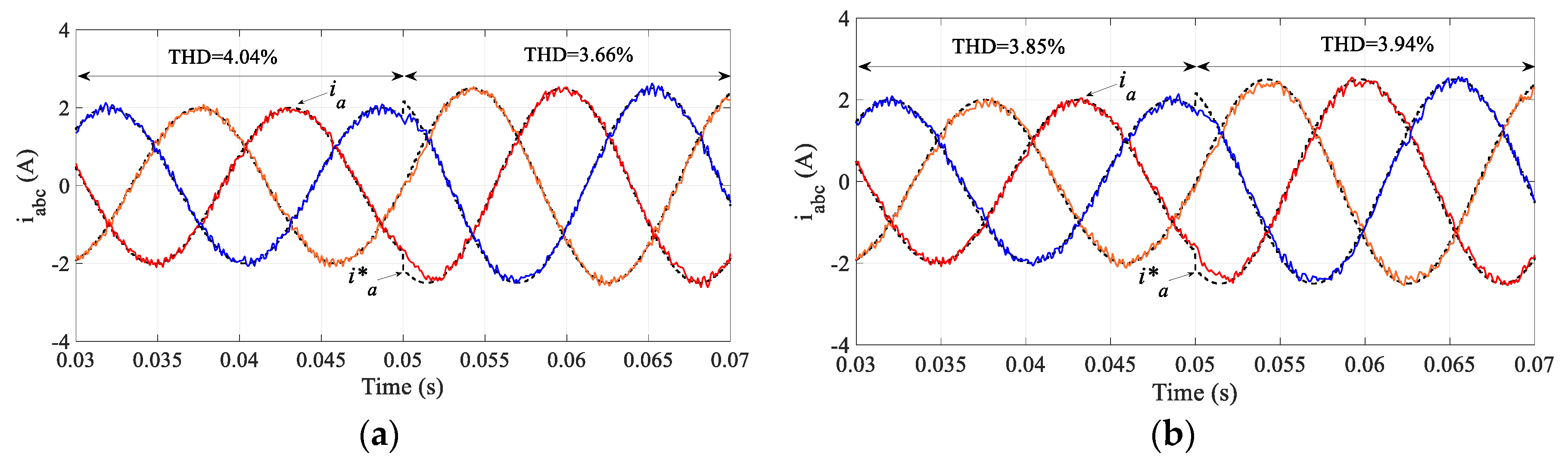
4. Simulation Results

To verify the effectiveness of the proposed controller, comparative simulation tests were carried out. The block diagram of the proposed SMPC for MC is shown in Figure 3. Here, two independent cost functions (g1 and g2) are used for the load current and input power factor, respectively. All 27 possible switching states are evaluated in the first cost function (g1) and two states are preselected. These two states are then evaluated in g2 to select the final switch state, which is applied in the controller. The system and controller parameters are tabulated in Table 3. The amplitude of the reference load current was set to 2 A. A unity power factor is desired, so the reactive power reference was set to zero. In the traditional MPC, a weighting factor of λ = 0.0008 was used, which was obtained by a lengthy trial-and-error process. In the simulation results, the black dashed lines represent the current reference waveform (e.g., ia*).
Figure 4 compares the performance of the output current regulation between the traditional MPC and the proposed SMPC. As observed in this figure, the performance of the proposed SMPC is very similar to the traditional MPC. The total harmonic distortion (THD) in the traditional MPC is 4.07% while it is 3.95% in the proposed SMPC.
Figure 5 compares the input power factor regulation of two methods. Both methods can regulate the input current, iSA, to be in phase with the input voltage, vSA, resulting in unity input power factor operation. As concluded from these results, the proposed SMPC exhibits comparable results to the traditional MPC. However, the complex weighting factor design is not required in the proposed SMPC.
The proposed SMPC reduces the computational burden and can potentially improve the performance further. Compared with the traditional MPC, the computation burden is reduced because only the pre-selected switch states are evaluated in the second and subsequent sequential cost functions. In addition, the prediction model computation for the following cost functions is also reduced. These further improve the performance by increasing the sampling frequency of the algorithm. However, this is difficult to achieve in the traditional MPC because all switch states are evaluated in all cost functions; otherwise, some pre-selection technique must be applied. To verify this benefit of the proposed SMPC, the sampling time was reduced to 80 μs, which complies with the experimental implementation in the following section. The simulation results for the proposed SMPC with Ts = 80 μs are shown in Figure 6. The regulated output current is improved in terms of the waveform and THD (3.31%) and the input waveform is also improved.
A comparative table of the performance is shown in Table 4. Under the same system conditions, the proposed SMPC performs similarly to the traditional MPC in terms of the evaluated performance with a slightly lower average switching frequency. These simulation results demonstrate the effectiveness of the proposed SMPC.
To test the dynamic performance, dynamic tests were carried out. Figure 7 shows the response of the output current to load variation. In this test, at 0.05 s, the load was increased to 1.5 times the original value. As seen, the output current still can be controlled to follow the prescribed reference. The corresponding results of the input power factor regulation are shown in Figure 8. In both controllers, an almost united input power factor is obtained. The output voltages corresponding to the load variation test are depicted in Figure 9.
In addition, we evaluated the performance of the controllers under a reference step change. The results of the regulated output currents are shown in Figure 10. The reference current amplitude was changed from 2 A to 2.5 A at 0.05 s. As can be seen from the results, the controller can track the reference with fast dynamics. It can be concluded from these results that the performance of the proposed SMPC is comparative to that of MPC. However, unlike MPC, the proposed SMPC does not require complex weighting factor tuning.

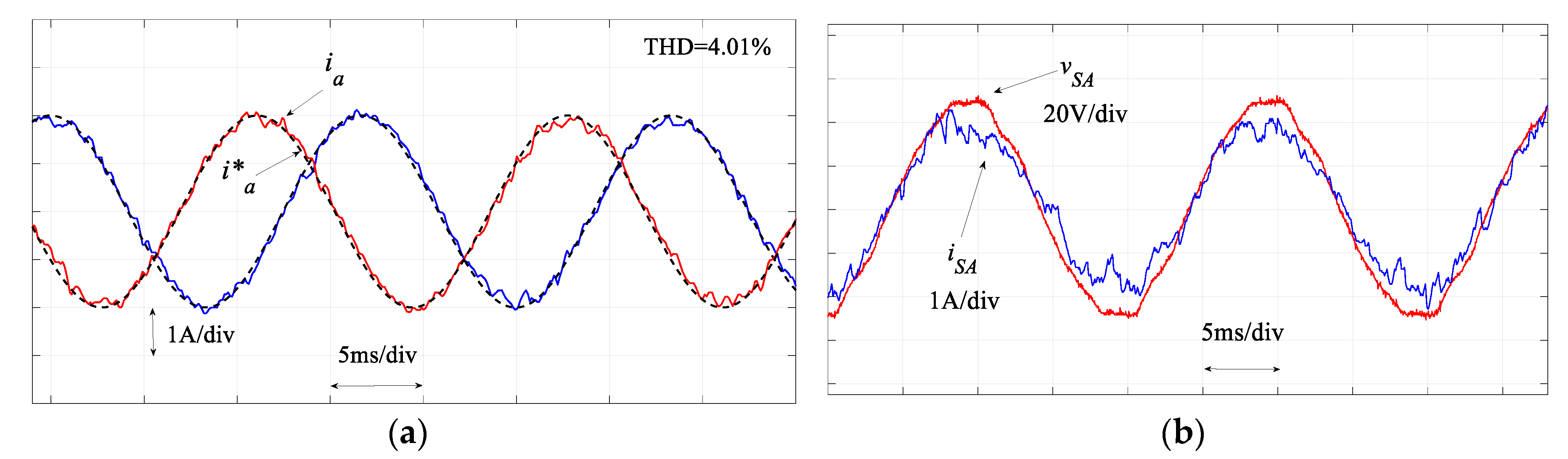
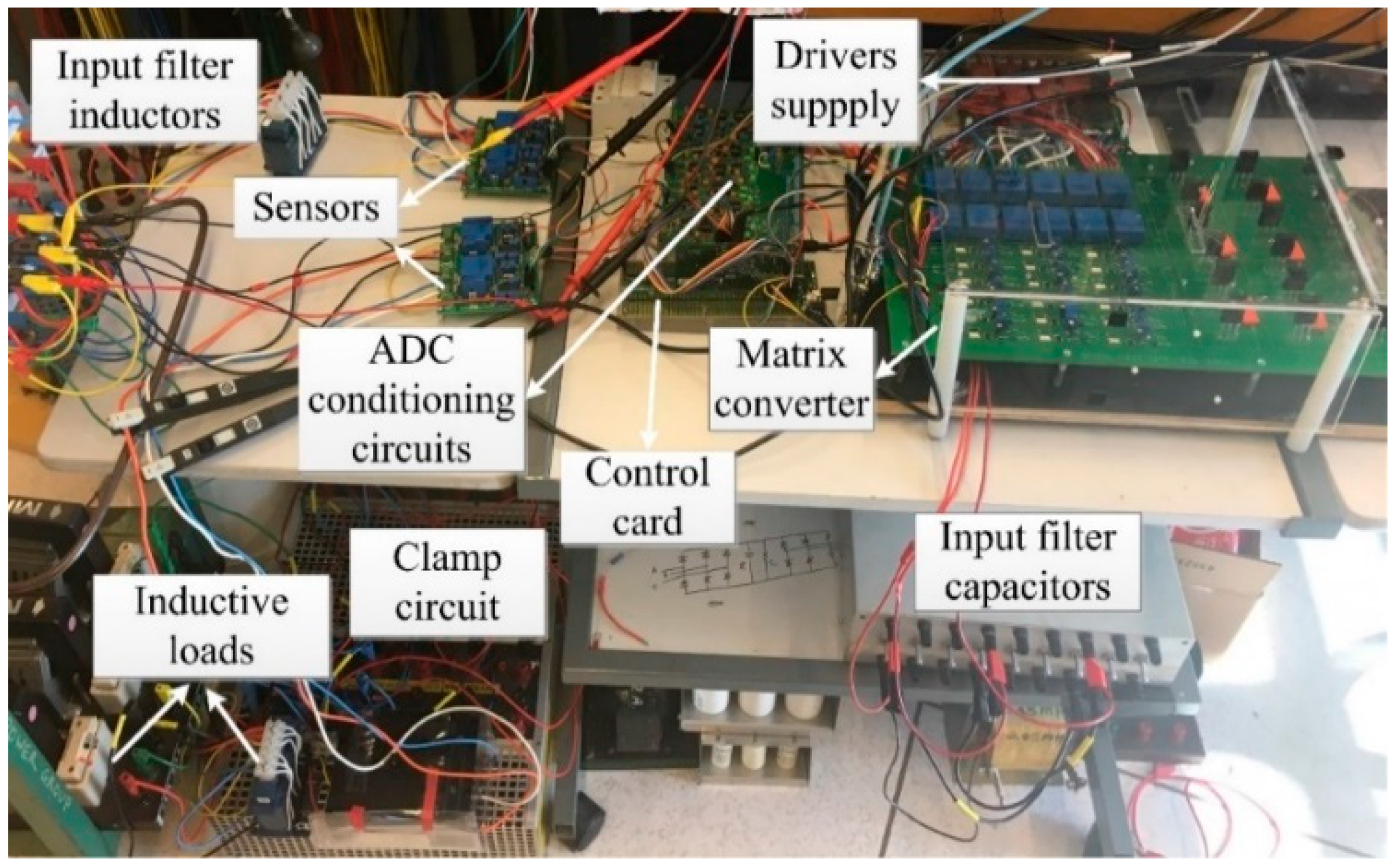
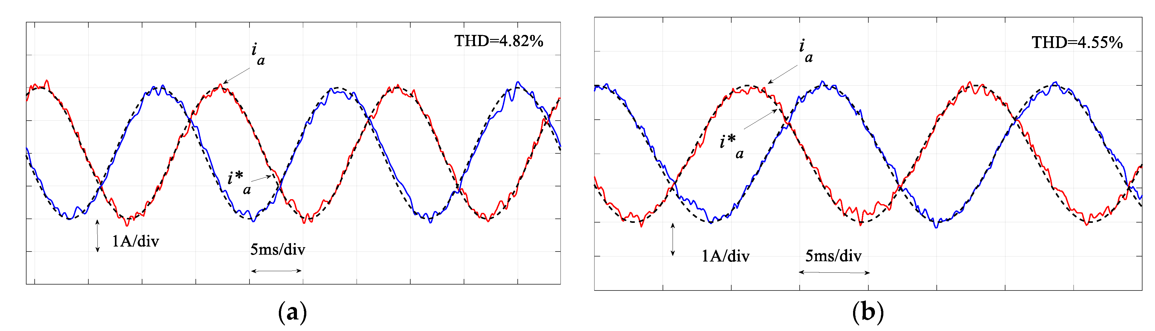
5. Experimental Verification

The experimental work was carried out on an MC prototype to verify the proposed controller. The hardware system is shown in Figure 11. The controller was implemented in a digital signal processor—TMS320F28377D Dual-Core Delfino Microcontroller. The tested system and controller parameters are the same as the simulation. For the experimental implementation, the total code execution time of the traditional MPC and the proposed MPC was 81 μs and 67 μs, respectively.
As mentioned in the simulation section, the execution time and computational burden are reduced because only the pre-selected switch states need to be evaluated in the second and subsequent cost functions. In addition, it requires less prediction model computation for the following cost functions. To carry out a fair comparison between the proposed SMPC and MPC, a sampling time of 100 μs was used. Comparative experimental results are presented below.
Figure 12 compares the regulated MC output currents and Figure 13 compares the performance in terms of the regulation of the input power factor. As seen in these figures, similar results for the traditional MPC and proposed SMPC are obtained. In the output current regulation, the THD for the traditional MPC is 4.82% and it is 4.55% for the proposed SMPC. These results confirm the simulation results. It is noted that the execution time of the proposed SMPC (67 μs) is reduced appreciably compared with the traditional MPC (81 μs). Therefore, the sampling time in the proposed SMPC can be reduced to 80 μs, which results in a better performance in both load currents and input power factor regulation, as shown in Figure 14. However, this is difficult to achieve in the traditional MPC; otherwise an overrun issue occurs in the practical implementation.
As concluded from the above comparative experimental results, the proposed SMPC is effective in regulating the load currents and input power factor of MC. Under the same system conditions, similar results to the traditional MPC can be obtained with the proposed SMPC strategy. The complex weighting factor design process is not required. Therefore, the design process is simplified.

6. Conclusions

A generalised SMPC was proposed for a three-phase direct MC in this paper. In the proposed SMPC strategy, each control objective has an individual cost function. These cost functions were evaluated in sequential order according to the pre-determined priority. Complex weighting factor design was avoided in the proposed strategy, which simplifies the controller design process. With the proposed control strategy, the cost functions corresponding to control objectives were evaluated individually and sequentially. In this way, the computational burden was reduced since only the pre-selected switch states will be evaluated in the subsequent cost functions. In addition, the computation of prediction models for the following cost functions was reduced as well. These enable further improvement of the control performance by increasing the sampling frequency. The priority of the control objectives was also specified with the proposed strategy. The achieved performance was comparative to that of the traditional MPC. The effectiveness of the proposed controller was verified by both the simulation and the experimental results. The proposed controller became more beneficial when more control objectives and more switch states were considered. So, this controller is suitable for MC. The proposed SMPC can be readily extended to other converters and systems.

Author Contributions

M.N., J.Z. and J.R. developed the idea. L.L. and D.D. verified the analysis and edited the paper. J.Z. carried out the simulation and experimental work.

Funding

This research was funded by FONDECYT grant number 11180233, and grant number 1170167 And the Chilean Research Council (CONICYT) through the Basal Project FB0008 “Advanced Center for Electrical and Electronic Engineering”.

Conflicts of Interest

The authors declare no conflict of interest.

References

  1. Wheeler, P.; Rodriguez, J.; Clare, J.C.; Empringham, L.; Weinstein, A. Matrix converters: A technology review. IEEE Trans. Ind. Electron. 2002, 49, 276–288. [Google Scholar] [CrossRef]
  2. Monteiro, J.; Pinto, S.; Delgado Martin, A.; Silva, J.F. A new real time lyapunov based controller for power quality improvement in unified power flow controllers using direct matrix converters. Energies 2017, 10, 779. [Google Scholar] [CrossRef]
  3. Zhang, J.; Li, L.; Dorrell, D.G. Control and Applications of Direct Matrix Converters: A Review. Chin. J. Electr. Eng. 2018, 4, 18–27. [Google Scholar] [CrossRef]
  4. Empringham, L.; Kolar, J.W.; Rodriguez, J.; Wheeler, P.W.; Clare, J.C. Technological issues and industrial application of matrix converters: A review. IEEE Trans. Ind. Electron. 2013, 60, 4260–4271. [Google Scholar] [CrossRef]
  5. Rodriguez, J.; Rivera, M.; Kolar, J.W.; Wheeler, P.W. A review of control and modulation methods for matrix converters. IEEE Trans. Ind. Electron. 2012, 59, 58–70. [Google Scholar] [CrossRef]
  6. Kolar, J.W.; Friedli, T.; Rodriguez, J.; Wheeler, P.W. Review of three-phase PWM AC–AC converter topologies. IEEE Trans. Ind. Electron. 2011, 58, 4988–5006. [Google Scholar] [CrossRef]
  7. Venturini, M. A new sine wave in sine wave out, conversion technique which eliminates reactive elements. Proc. Powercon 1980, 7, E3/1–E3/15. [Google Scholar]
  8. Rodriguez, J.; Silva, E.; Blaabjerg, F.; Wheeler, P.; Clare, J.; Pontt, J. Matrix converter controlled with the direct transfer function approach: Analysis, modelling and simulation. Int. J. Electron. 2005, 92, 63–85. [Google Scholar] [CrossRef]
  9. Huber, L.; Borojevic, D. Space vector modulated three-phase to three-phase matrix converter with input power factor correction. IEEE Trans. Ind. Appl. 1995, 6, 1234–1246. [Google Scholar] [CrossRef]
  10. Zhang, J.; Dorrell, D.G.; Li, L.; Guo, Y. Decoupling Controller Design and Controllable Regions Analysis for the Space Vector Modulated Matrix Converter-Unified Power Flow Controller in Transmission Systems. Electr. Power Compon. Syst. 2018, 46, 1–14. [Google Scholar] [CrossRef]
  11. Casadei, D.; Serra, G.; Tani, A. The use of matrix converters in direct torque control of induction machines. IEEE Trans. Ind. Electron. 2001, 48, 1057–1064. [Google Scholar] [CrossRef]
  12. Ortega, C.; Arias, A.; Caruana, C.; Balcells, J.; Asher, G. Improved waveform quality in the direct torque control of matrix-converter-fed PMSM drives. IEEE Trans. Ind. Electron. 2010, 57, 2101–2110. [Google Scholar] [CrossRef]
  13. Zhang, J.; Li, L.; Zhang, L.; Dorrell, D.G. Hysteresis Band Current Controller based Field-Oriented Control for an Induction Motor driven by a Direct Matrix Converter. In Proceedings of the 43rd Annual Conference of the IEEE Industrial Electronics Society (IECON 2017), Beijing, China, 29 October–1 November 2017; pp. 4633–4638. [Google Scholar] [CrossRef]
  14. Zhang, J.; Yang, H.; Wang, T.; Li, L.; Dorrell, D.G.; Lu, D.D.C. Field-Oriented Control based on Hysteresis Band Current Controller for a Permanent Magnet Synchronous Motor driven by a Direct Matrix Converter. IET Power Electron. 2018, 11, 1277–1285. [Google Scholar] [CrossRef]
  15. Rivera, M.; Rojas, C.; Rodriguez, J.; Wheeler, P.; Wu, B.; Espinoza, J.R. Predictive current control with input filter resonance mitigation for a direct matrix converter. IEEE Trans. Power Electron. 2011, 26, 2794–2803. [Google Scholar] [CrossRef]
  16. Wang, L.; Dan, H.; Zhao, Y.; Zhu, Q.; Peng, T.; Sun, Y.; Wheeler, P. A finite control set model predictive control method for matrix converter with zero common-mode voltage. IEEE J. Emerg. Sel. Top. Power Electron. 2018, 6, 327–338. [Google Scholar] [CrossRef]
  17. Zhang, J.; Li, L.; Malekjamshidi, Z.; Dorrell, D.G. Predictive Voltage Control of Direct Matrix Converter with Reduced Number of Sensors for the Renewable Energy and Microgrid Applications. In Proceedings of the IEEE Energy Conversion Congress Exposition (ECCE), Cincinnati, OH, USA, 1–5 October 2017; pp. 3309–3315. [Google Scholar] [CrossRef]
  18. Rivera, M.; Wilson, A.; Rojas, C.A.; Rodriguez, J.; Espinoza, J.R.; Wheeler, P.W.; Empringham, L. A comparative assessment of model predictive current control and space vector modulation in a direct matrix converter. IEEE Trans. Ind. Electron. 2013, 60, 578–588. [Google Scholar] [CrossRef]
  19. Vazquez, S.; Leon, J.I.; Franquelo, L.G.; Rodriguez, J.; Young, H.A.; Marquez, A.; Zanchetta, P. Model predictive control: A review of its applications in power electronics. IEEE Ind. Electron. Mag. 2014, 8, 16–31. [Google Scholar] [CrossRef]
  20. Hu, S.; Liu, G.; Jin, N.; Guo, L. Constant-Frequency Model Predictive Direct Power Control for Fault-Tolerant Bidirectional Voltage-Source Converter with Balanced Capacitor Voltage. Energies 2018, 11, 2692. [Google Scholar] [CrossRef]
  21. Rodriguez, J.; Kazmierkowski, M.P.; Espinoza, J.R.; Zanchetta, P.; Abu-Rub, H.; Young, H.A.; Rojas, C.A. State of the art of finite control set model predictive control in power electronics. IEEE Trans. Ind. Inform. 2013, 9, 1003–1016. [Google Scholar] [CrossRef]
  22. Norambuena, M.; Rodriguez, J.; Zhang, Z.; Wang, F.; Garcia, C.; Kennel, R. A Very Simple Strategy for High Quality Performance of AC Machines Using Model Predictive Control. IEEE Trans. Power Electron. 2018. [Google Scholar] [CrossRef]
  23. Cortés, P.; Kouro, S.; La Rocca, B.; Vargas, R.; Rodríguez, J.; León, J.I.; Vazquez, S.; Franquelo, L.G. Guidelines for weighting factors design in model predictive control of power converters and drives. IEEE Int. Conf. Ind. Technol. 2009, 1–7. [Google Scholar] [CrossRef]
  24. Rojas, C.A.; Rodriguez, J.; Villarroel, F.; Espinoza, J.R.; Silva, C.A.; Trincado, M. Predictive torque and flux control without weighting factors. IEEE Trans. Ind. Electron. 2013, 60, 681–690. [Google Scholar] [CrossRef]
  25. Zhang, Y.; Yang, H. Two-vector-based model predictive torque control without weighting factors for induction motor drives. IEEE Trans. Power Electron. 2016, 31, 1381–1390. [Google Scholar] [CrossRef]
  26. Zanchetta, P. Heuristic multi-objective optimization for cost function weights selection in finite states model predictive control. In Proceedings of the IEEE Workshop Predictive Control Electrical Drives Power Electron, Munich, Germany, 14–15 October 2011; pp. 70–75. [Google Scholar] [CrossRef]
  27. Davari, S.; Khaburi, D.A.; Kennel, R. An improved FCS–MPC algorithm for an induction motor with an imposed optimized weighting factor. IEEE Trans. Power Electron. 2012, 27, 1540–1551. [Google Scholar] [CrossRef]
Figure 1. Three-phase direct MC.
Energies 12 00214 g001
Figure 2. Systematic diagram of the SMPC strategy.
Energies 12 00214 g002
Figure 3. Block diagram of SMPC applied to an MC.
Energies 12 00214 g003
Figure 4. Simulation results of regulated load currents by (a) MPC, and (b) proposed SMPC.
Energies 12 00214 g004
Figure 5. Simulation results of regulated input power factor by (a) MPC, and (b) proposed SMPC.
Energies 12 00214 g005
Figure 6. Simulation results of (a) regulated currents and (b) input power factor by the proposed SMPC when Ts = 80 μs.
Energies 12 00214 g006
Figure 7. Response of output currents to load variation: (a) MPC and (b) proposed SMPC.
Energies 12 00214 g007
Figure 8. Response of input power factor to load variation: (a) MPC and (b) proposed SMPC.
Energies 12 00214 g008
Figure 9. MC output line-line voltage under load variation: (a) MPC and (b) proposed SMPC.
Energies 12 00214 g009
Figure 10. Response of the output current to reference step change: (a) MPC and (b) proposed SMPC.
Energies 12 00214 g010
Figure 11. MC prototype setup.
Energies 12 00214 g011
Figure 12. Experimental results of regulated load currents by (a) MPC and (b) proposed SMPC.
Energies 12 00214 g012
Figure 13. Experimental results of regulated input power factor by (a) MPC and (b) proposed SMPC.
Energies 12 00214 g013
Figure 14. Experimental results of (a) regulated currents and (b) input power factor by the proposed SMPC when Ts = 80 μs.
Energies 12 00214 g014
Table 1. Summarized Information of some MC related commercial products.
ManufacturersProduct/ModelMax. VoltageMax. PowerTarget ApplicationOther Information/Feature
YaskawaFSDrive-MX1S6.6 kV6 MVAmotor driveenergy-saving
YaskawaU1000480 V800 HPmotor drivefull regeneration, ultra-low harmonics
YaskawaAC7480 V250 HPmotor drivelegacy product
YaskawaZ1000U480 V350 HPHVAC applicationslow input distortion
EupecECONOMAC FM35R12KE3ENG1200 V42 kVAunspecifiedmodule
FujiFRENIC-Mx400 V45 kWgeneral industrial machinesbest suitable for elevators and cranes
Table 2. Performance comparison of some control techniques for MCs.
FeaturesVenturini ControlSpace Vector ModulationDirect Torque ControlPredictive ControlHysteresis Control
Complexitylowhighmediumlowvery low
Sampling Frequencyvery lowlowvery highhighhigh
Switching Frequencyvery lowlowhighhighhigh
Dynamic Responsegoodgoodfastvery fastvery fast
Application Range narrowwidenarrowvery widemedium
Table 3. System and controller parameters.
vs [Vpk-pk]fs [Hz]LA [mH]CA [μF]RA [Ω]RL [Ω]LL [mH]fo [Hz]Q* [VAr]Ts [μs]
100506.8100.51514600100
Table 4. Comparative performance evaluation of SMPC and MPC.
MethodsTsAvg. Switching FrequencyWeighting FactorOutput Current THDInput Power Factor
MPC100 μs2.038 kHz0.00084.07%0.997
SMPC1100 μs1.89 kHznone3.95%0.996
SMPC280 μs2.37 kHznone3.31%0.997

