Article

A Numerical Study of Axisymmetric Wave Propagation in Buried Fluid-Filled Pipes for Optimizing the Vibro-Acoustic Technique When Locating Gas Pipelines

1
Centre for Communications and Electronics Research, School of Engineering, Edith Cowan University, Joondalup, Perth WA6027, Australia
2
State Key Laboratory of Acoustics, Institute of Acoustics, Chinese Academy of Sciences, Beijing 100190, China
3
University of Chinese Academy of Sciences, Beijing 100049, China
4
Beijing Engineering Research Center of Sea Deep Drilling and Exploration, Institute of Acoustics, Chinese Academy of Sciences, Beijing 100190, China
*
Author to whom correspondence should be addressed.
Energies 2019, 12(19), 3707; https://doi.org/10.3390/en12193707
Submission received: 17 June 2019 / Revised: 17 August 2019 / Accepted: 19 September 2019 / Published: 27 September 2019
(This article belongs to the Section D: Energy Storage and Application)

Abstract

:
Buried pipeline systems play a vital role in energy storage and transportation, especially for fluid energies like water and gas. The ability to locate buried pipes is of great importance since it is fundamental for leakage detection, pipeline maintenance, and pipeline repair. The vibro-acoustic locating method, as one of the most effective detection technologies, has been studied by many researchers. However, previous studies have mainly focused on vibro-acoustic propagation in buried water pipes. Limited research has been conducted on buried gas pipes. In this paper, the behavior of gas-dominated wave motion will be investigated and compared against water-dominated wave motion by adapting an established analytical model of axisymmetric wave motion in buried fluid-filled pipes. Furthermore, displacement profiles in spatial domain resulting from gas-dominated wave in buried gas pipeline systems will be analyzed, and the effects of pipe material, soil property, as well as mode wave type will be discussed in detail. An effective radiation coefficient (ERC) is proposed to measure the effective radiation ability of gas-dominated wave and water-dominated wave. It is observed that the gas-dominated wave in gas pipes cannot radiate into surrounded soil as effectively as water-dominated wave in water pipes because of the weak coupling between gas and pipe-soil. In this case, gas-dominated wave may not be the best choice as the target wave for locating buried gas pipes. Therefore, the soil displacements result from the shell-dominated wave are also investigated and compared with those from gas-dominated wave. The results show that for buried gas pipes, the soil displacements due to radiation of shell-dominated wave are stronger than gas-dominated wave, which differs from buried water pipe. Hence, an effectively exciting shell-dominated wave is beneficial for generating stronger vibration signals and obtaining the location information. The findings of this study provide theoretical insight for optimizing the current vibro-acoustic method when locating buried gas pipes.

1. Introduction

Pipeline systems are one of the most effective means for storing and transporting fluid energies, and it has been the subject of numerous studies [1,2,3]. Leakage in these pipeline systems, which are often buried under ground, can occur from time to time, leading to economic losses and environmental problems [4,5]. Identifying the location of pipelines of interest is of great significance as it is the prerequisite of leakage detection and condition assessment. Unfortunately, records of the location of these underground utilities are often inaccurate and incomplete. To address this problem, the vibro-acoustic technique has been developed and has been shown to be promising in locating buried plastic water pipes [6]. By applying contact or non-contact excitation to the buried pipe, the pipe location can be detected through extracting the phase of the surface vibration using surface mounted geophones. Such a technique has been proven to be extremely robust [7].
In addition to being employed for locating buried pipes, vibro-acoustic signals have been widely adopted in order to achieve leak detection [8,9]. Numerous studies focusing on wave propagation on pipe structure have been conducted for many years. Gazis has investigated the harmonic waves in hollow circular cylinders of infinite extent in three dimensions and obtained a characteristic equation, thereby providing an analytical foundation [10] as well as numerical results [11]. Fuller and Fahy [12] have studied the dispersion characteristics and energy distributions of free waves in fluid-filled thin shell, where the concept of fluid loading term was first proposed. Based on this, the vibration and radiation characteristics of the shell excited by an internal monopole acoustic source have also been analyzed [13,14]. Pinnington and Briscoe [15] found that well below the pipe ring frequency (usually at least 1000 Hz) four wave types make contributions to the most energy transmission: these are the three axisymmetric waves, with n = 0, and s = 1, 2, and 0, corresponding to a fluid-dominated wave, shell-dominated wave, and torsional wave, respectively. (In this paper, to distinguish different scenarios, s = 1 wave is straightforwardly named in terms of the type of inner fluid, like a water-dominated wave and gas-dominated wave.) The fourth, the n = 1 wave, relates to beam bending. The pipe-structure models mentioned above are mainly limited in the circular cylinder or shell surrounded by vacuum, where recently, most efforts have focused on the fluid-filled pipes surrounded by some medium which is the most common situation in practice.
Sinha et al. have investigated dispersion curves and displacement and stress distributions along the radial direction of a liquid-filled cylinder immersed in liquid [16] and conducted experiments to verify the theory [17]. Long et al. have presented possible axisymmetric wave modes propagating in buried iron pipes filled with water [18], as well as the attenuation behaviors of the fundamental mode waves [19]. Muggleton et al. [20] have developed an analytical model and derived equations to predict the wavenumber of two wave types, s = 1 (fluid-dominated) and s = 2 (shell-dominated) wave, in a fluid-filled pipe surrounded by an infinite elastic medium. However, the outer medium was treated as fluid which can sustain both compressional and shear wave, and the shear coupling between the pipe and the surrounding soil was not properly accounted for. The modal was improved by including shear coupling for a buried fluid-fill pipe at a lubricated pipe/soil interface [21]. Gao et al. [22] proposed a simplified analytical model to predict the dispersion relationships for fluid-dominated wave and investigated structural and fluid motion [23] in buried fluid-fill pipes, which provides theoretical support for axisymmetric wave propagation in buried fluid-filled pipe systems with perfect bonding in pipe-soil interface. For the water pipe, where the inner fluid and the pipe wall are well coupled, the s = 1 wave (water-dominated wave) will be the predominant energy carrier [15] and it can radiate into surrounding soil while propagating down the pipe. Therefore, s = 1 wave is always the target wave of vibro-acoustic method in locating buried water pipes and different excitation methods have been specifically designed to determine the best way to excite this wave type [24]. By effectively exciting the water-dominated wave and analyzing the ground surface vibration resulting from this mode wave, the location of buried water pipe can be determined [25]. Despite a great deal of research having been carried out on buried pipe systems, the cases are only restricted to water pipes, while limited work has been conducted on buried gas pipes. The situation may be different for buried gas pipes due to the weak coupling between gas and the pipe wall. Jette and Parker [26] investigated the surface displacements resulting from the acoustic wave propagation within a buried gas pipe, which provided a theoretical frame to the study of wave field in gas pipe systems. Li et al. [27] have investigated the leakage acoustic vibration of gas pipes in air, indicating that the s = 2 wave (shell-dominated wave) is the prominent component of the gas leakage-induced acoustic wave, which is contrary to the conclusion for water pipes in [15,23]. Therefore, understanding acoustic propagation behavior of buried gas pipes and distinguishing the differences from buried water pipes are both significantly important for locating pipelines and detecting leakage.
In this paper, axisymmetric waves and displacement profiles in radial direction for buried gas pipe systems are studied with a comparison against water pipes. The investigation starts with the fundamental theory of axisymmetric wave motion in a buried pipe system in Section 2. This is based on a simplified analytical model of axisymmetric wave motion in buried fluid-filled pipes [22]. The numerical results are presented in Section 3. Firstly, the dispersion characteristics of gas-dominated wave for buried gas pipes are analyzed and compared with water-dominated wave in Section 3.1. Following this, in Section 3.2, the displacement distributions resulting from gas-dominated wave of buried gas pipe systems are investigated, and compared against those of buried water pipes. Furthermore, in Section 3.3, the displacement profiles resulting from shell-dominated wave (termed s = 2) in buried gas pipes are also investigated to reveal another wave motion shape of soil. The limitations and suggestion for optimizing the current vibro-acoustic method are included in Section 4. Finally, some conclusions are drawn in Section 5.

2. Theory

2.1. Model Introduction and Nomenclature

The three dimensional coordinated system of a fluid-filled (gas or water) pipe surrounded by infinite soil is depicted in Figure 1. The three directions of cylindrical coordinate are shown as x (axial), r (radial), and θ (circumferential). Since only axisymmetric wave motion is taken into consideration, only the variations with respect to x (axial) and r (radial) exist.
The fluid inside the pipe could be gas or water. The pressure of the fluid is represented by p f . The normal stress and shear stress from soil loading can be expressed as σ r r and σ r x , respectively. The displacements of pipe are represented by u p and w p in axial and radial direction, correspondingly. Likewise, the displacement of fluid and surrounded soil are represented by u f ,   w f and u m ,     w m , respectively. The pipe has a radius a = 0.08 m and a wall thickness h = 0.01 m, and they satisfy h/a   1.
For each s wave, the wave number is expressed as   k s . Parameters related to the pipe are described as ρ p , E p , and σ p , denoting density, Young’s modulus, and Poisson’s ratio, respectively. The shell compressional wave speed is v L = E p / ρ p ( 1 σ p 2 ) and the corresponding wave number is k L = ω / v L , where ω   is the angle frequency. Ω is the normalized ring frequency, which equals to   a k L 2 .
For a fluid-filled (gas or water) pipe, ρ f and v f are density and free field wave speed of the fluid. Axial wave number is k f = ω v f . The radial wave numbers are k f s r = k f 2 k s 2 .
Parameters related to the external medium are described as ρ m , μ m , λ m corresponding to density, shear modulus and Lamé elastic constant, respectively. The propagation wave speeds are v d = ( λ m + 2 μ m ) / ρ m for P-wave and v r = ( λ m + 2 μ m ) / ρ m for S-wave. The axial wave numbers are k d = ω / v d and k r = ω / v r . The radial wave numbers are k ds r = k d 2 k s 2 for P-wave and k r s r = k r 2 k s 2 for S-wave.

2.2. The Expressions of Axisymmetric Waves

Based on the simplified dispersion relationship of axisymmetric wave in buried fluid-filled pipes [22], the expression of s = 1 wave is reproduced here for completeness.
For s = 1 wave, according to the dispersion equation in Appendix A and assuming that the wave speed of gas-dominated wave is much smaller than the wave speed of shell compressional speed, i.e., k 1 << k L , the simplified characteristic equation for gas-dominated wave is given by [22]:
k 1 2 = k f 2 ( 1 + β 1 Ω 2 + α )
where α = S L 22 ( σ p i S L 12 / k 1 a ) 2 1 + S L 11 / ( k 1 a ) 2 and β = 2 c f 2 ρ f a ( 1 σ p 2 ) / E p h . The expression of S L can be found in Appendix A. The attenuations are defined by the loss in dB per unit propagation distance (measured in pipe radii) by [22]:
Loss ( dB / unit   distance   a ) = 20 Im ( k s a ) ln ( 10 )

2.3. Equations of the Radial Displacement Distribution in Radial Direction

For the buried pipe system, the pressure of the inner fluid can be measured more easily compared to other parameters. Therefore, the amplitude of fluid pressure at center of the system is selected to be the normalization. Setting r = 0 in Equation (A3), it renders:
p f s ( 0 ) = P f s e i ( ω t k s x )
In this way, P fs is the normalization, where all the displacements will be normalized by it.
For the fluid inside the pipe, substitute Equation (A3) into Equation (A4), where the fluid displacements can be expressed as:
w f s = k f s r J 1 ( k f s r r ) ρ f ω 2 P f s e i ( ω t k s x ) ,   u f s = i k s J 0 ( k f s r r ) ρ f ω 2 P f s e i ( ω t k s x )
Therefore, the normalized amplitudes of in-pipe gas displacements are:
W ˜ f s = k f s r J 1 ( k f s r r ) ρ f ω 2 ,   U ˜ f s = i k s J 0 ( k f s r r ) ρ f ω 2
For the displacement of pipe wall, rearrange the order of Equation (A11), given that [23]:
W p s = Υ s P f s
From Equation (A18), there is:
U p s = χ s W p s
where   χ s = 1 Ω 2 FL SL 22 i σ p k s a + SL 21 [23]. Therefore, the normalized amplitudes of radial displacement of pipe wall are:
W ˜ p s = Υ s ,   U ˜ p s = χ s Υ s
Eliminating the term e i ( ω t k s x ) in Equation (A7), the amplitudes of soil displacements are given as:
( U m s W m s ) = T 1 ( A m s B m s )
The terms related to A m s and B m s represent the contributions from compressional wave and shear wave in soil, respectively. The terms related to A ms and B ms represent the contributions from compressional wave and shear wave in soil, respectively.
Equation (A15) and Equations (6) and (7) yield:
( A m s B m s ) = [ N 11 N 12 N 21 N 22 ] ( Υ s P fs χ s Υ s P fs )
Therefore, by combining Equations (9) and (10), the normalized displacement of soil can be expressed as:
( U ms ˜ W ms ˜ ) = T 1 [ N 11 N 12 N 21 N 22 ] ( Υ s χ s Υ s )

3. Numerical Results and Analysis

This section presents the numerical results and analysis of the dispersion behavior of axisymmetric waves and displacement radial profiles of buried gas pipes. The property of gas is set the same as air for simplicity. Two different pipe materials are considered, namely, polyvinyl chloride (PVC) and cast iron. Furthermore, two different soil types are included in the study: soil A represents a typical sandy soil and soil B represents a typical clay soil. The numerical results of buried water pipes are also presented for comparative purposes. The parameters used are listed in Table 1, which provide consistency with the studies conducted in references [22,23].

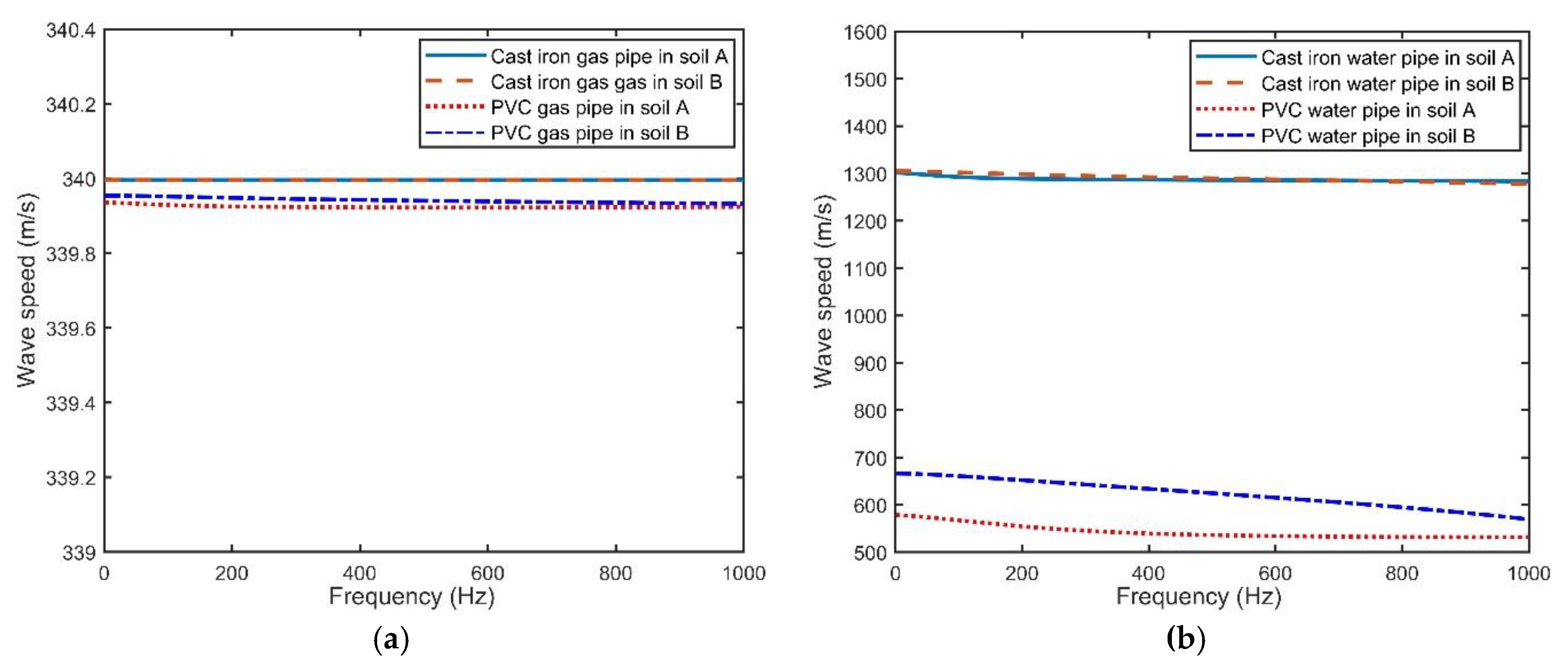
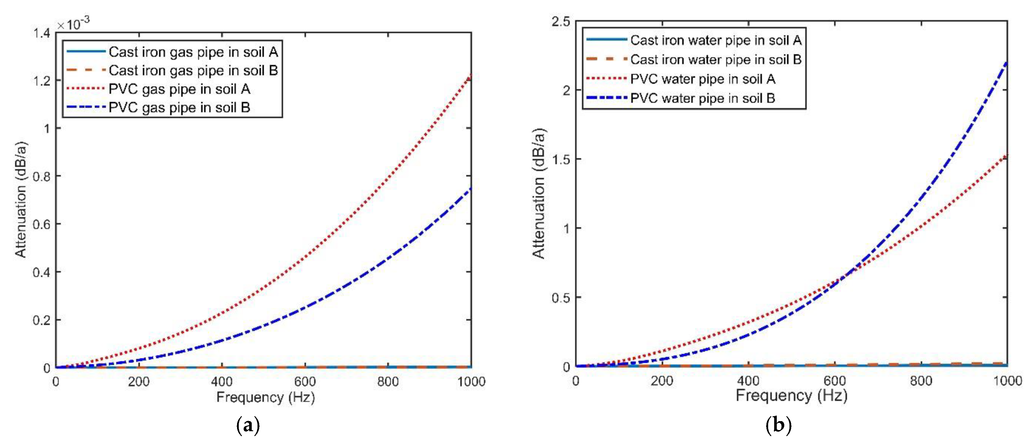
3.1. Characteristics of the s = 1 Wave in Buried Gas Pipes versus Buried Water Pipes

The dispersion curve and attenuation of gas-dominated wave for buried gas pipes are illustrated in Figure 2a and Figure 3a, with those of the water pipes for comparison shown in Figure 2b and Figure 3b.
For water pipes, as shown in Figure 2b, both pipe material and soil property have impacts on the speed of water-dominated wave, even if it can be approximately treated as non-dispersive over the frequency range of interest for fixed pipe material and soil. The impact of soil property is very slight for cast iron pipes and discernable on PVC pipes. This can be revealed in plots where the wave speeds almost remain the same for cast iron pipes buried in different soil types, whereas slight variation appears for PVC pipes. However, the impact of pipe material is prominent. The change of pipe material causes a huge variation, demonstrated by the speeds of water-dominated waves for PVC water pipes being significantly smaller than cast iron pipes. This occurs because the inner fluid directly contacts with the pipe wall. In addition, the acoustic impedance difference between water and PVC is relatively small, leading to better coupling between the pipe wall and inner fluid for PVC pipe. In this case, the soil property could effectively impact the behavior of the s = 1 wave. For cast iron pipes, the great disparity of acoustic impedance between cast iron and the water makes the pipe wall a barrier against the soil, implying that the soil property hardly has any influence on the s = 1 wave. This phenomenon is verified in Figure 3b where attenuation of the water-dominated wave is displayed, shown with little variation for cast iron pipe in different soil types, whereas the variation is discernable for PVC pipes.
The above phenomenon is also reflected in Figure 3a. However, the characteristics of the s = 1 wave are quite different from those of a water pipe when looking at the magnitude scale of variation. The speed differences of the four buried gas pipes shown in Figure 3a are extremely small, less than 0.015 m/s, and the speed values are around 339 m/s. This means that the pipe material and soil type almost have no effect on the speed of gas-dominated wave, where it propagates at a speed very close to the air in the free field (340 m/s). The behaviors of gas-dominated wave can be explained by the huge acoustic impedance difference between gas and the pipe material, which is so large that the coupling between gas and pipe is extremely weak. Therefore, in general, inner gas and pipe-soil can be approximately regarded as separated, implying that the gas-dominated wave is relatively dependent and hardly affected by pipe and soil.
The attenuations of gas-dominated waves and water-dominated waves in different cases follow similar patterns as depicted in Figure 3a,b. The attenuation of PVC water pipe is much greater than for the cast iron pipe due to the smaller acoustic impedance difference between PVC and in-pipe fluid. This will generate better coupling and consequently, the s = 1 wave can radiate more easily outward to the pipe and the surrounded soil, leading to a greater attenuation during propagation in an axial direction. However, when looking at the magnitude scale, it is evident that the attenuation for gas pipe is at much lower level than water pipe. This is also because of the weak coupling between inner gas and pipe-soil. As mentioned previously, good coupling will result in a large amount of radiation into soil accompanying high level of attenuation in axial direction, which implies that the gas-dominated wave is mainly trapped inside the pipe and may not radiate effectively into soil as it propagates down the pipe.
An earlier study has demonstrated a vibro-acoustic technique for locating buried pipes, where the ground vibration due to the radiation of the s = 1 wave is employed to identify the run of a buried water pipe [25]. This detection method has been successful in locating buried water pipes, while the feasibility of locating buried gas pipe remains unknown based on the different behaviors between gas-dominated and water-dominated wave. To clarify this question, the effective radiation ability of gas-dominated wave will be investigated and discussed in detail in Section 3.2.

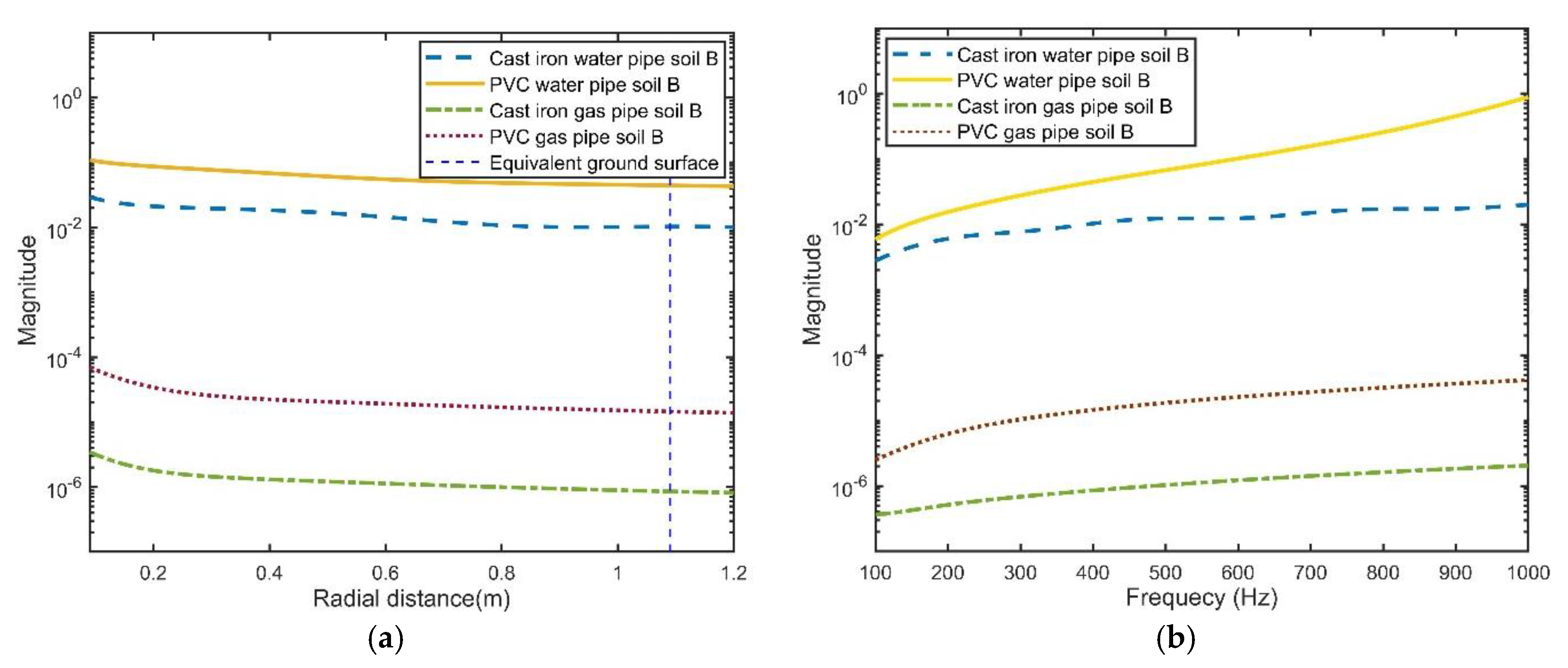
3.2. Displacement Profiles from the s = 1 Wave (Gas-Dominated Wave) for Buried Gas Pipe: With a Buried Water Pipe as a Reference

The cross section of buried fluid-filled pipe shown in Figure 1, is further depicted in Figure 4, rotated by 90°. The central axis is shown as a black dashed line with a dashed blue line depicting the equivalent ground surface away from pipe wall around 1 m, corresponding to the standard burial depth of most pipelines. In this way, the x-axes of displacement profiles displayed in Figure 5 and Figure 6 corresponds to the radial direction in Figure 4, where y-axes can straightforwardly present the magnitude scale.
To study the effect of pipe material and soil type on the vibration behavior of buried gas piping system, the displacement profiles of four cases are illustrated in Figure 5a,b and Figure 6a,b, including cast iron gas pipe buried in soil A, PVC gas pipe buried in soil A, cast iron gas pipe buried in soil B and PVC gas pipe buried in soil B. For comparison, corresponding water pipes of the same pipe material buried in the same soil type are displayed in Figure 5c,d and Figure 6c,d. In each graph, the overall axial displacement as well as the contributions from P wave and S wave are plotted. The pattern of contributions from P and S wave to radial displacement is similar. Therefore, for radial displacement, only overall value is displayed for clarity.
The displacements resulting from s = 1 wave are characterized by the great magnitude of axial displacement in fluid inside the pipe. This is exactly why the s = 1 wave is called the fluid-dominated wave. Moreover, the displacements in pipe and surrounding soil reveal that s = 1 wave is a waveguide spreading through the entire buried pipe structure, including the inner fluid, pipe and the outer soil. However, the wave dampens during the radiation away from the in-pipe fluid as the overall amplitude of soil displacement decreases with increasing distance in radial direction, even if there are fluctuations in some cases.
By comparing the different cases, some analysis can be made, which is detailed below.

3.2.1. The Effect from Pipe Material

Comparing Figure 5a,b as well as Figure 6a,b, it is evident that the displacements of buried PVC water systems are at a higher magnitude level than buried cast iron water pipes, in both an axial and radial direction. This finding can also be applied to buried gas pipe when comparing Figure 5c,d as well as Figure 6c,d. The only difference is that the axial displacements of inner fluid vary for different materials in water pipes, whereas they remain the same in gas pipes. This phenomenon corresponds to the huge variation of the wave speed of water-dominated wave between PVC and cast iron pipe, with almost unchanged wave speed of gas-dominated waves, which has been discussed in Section 3.1. The greater amplitudes of soil displacements for PVC pipes indicate that the PVC pipes are easier to excite than cast iron pipes because of the less pipe wall mass and less inertia. Therefore, the vibro-acoustic method is more feasible for locating buried PVC pipes.

3.2.2. The Effect from Soil Property

The effect of soil property on the vibration of buried pipe systems mainly depends on the relationship between the s = 1 wave speed and the speed of bulk waves in soil. According to Snell’s law, for the mode wave whose phase velocity is above bulk wave velocity of soil, it couples energy into the surrounding soil layer as propagating down the pipe and creates a leaky bulk wave at a characteristic angle [28]. For the pipes buried in soil A, as displayed in Figure 5a–d, the speed of s = 1 waves (around 339 m/s for gas pipes, around 1300 m/s for cast iron water pipes, 500–700 m/s for PVC water pipes) are greater than both compressional and shear wave velocity of soil. Therefore, both bulk waves make contributions to radiation, which is characterized by the synchronized damping of P wave and S wave in radial direction. The interfering effect of two waves, reflected as the oscillatory nature of the displacement in soil, is especially distinctive in Figure 5b,d, which confirms both contributions.
For the mode wave whose phase velocity falls below the bulk velocity of the surrounding medium, the characteristic angle is imaginary [28]. Instead of creating a wave that propagates away from the pipe, the energy is trapped inside the pipe and the soil displacement dampens rapidly in radial direction [18]. This is exactly the cases with pipes buried in soil B where the s = 1 wave speed is lower than the compressional wave speed of soil, as displayed in Figure 6a–d. Rather than damping parasynchronously with shear wave, the contribution from compressional waves decrease rapidly away from the pipe wall, which is more evident for buried gas pipe shown in Figure 6c,d. In these cases, the displacements of soil are only from the contribution due to shear waves so that the interfering effect is weak. As a result, the fluctuations in displacement of soil are not apparent.

3.2.3. The Difference between Gas Pipes and Water Pipes

By comparing the displacement shape of the gas pipe in Figure 5c to that of the water pipe in Figure 5a, it can be observed that the displacement difference between in-pipe fluid and surrounding soil in buried gas pipe systems is much greater than water pipe systems. This is also apparent when looking at Figure 5b,d, and Figure 6. To assess these differences in a straightforward manner, the effective radiation coefficient (ERC) is proposed, which is defined as the ratio of radial displacement of outer soil to that of in-pipe fluid at the center of the axis, given by:
Effective   Radiation   Coefficient   ( ERC ) = U ˜ m s U ˜ f s | r   =   0
The characteristics of ERC have been investigated for 8 cases, corresponding to Figure 5a–d and Figure 6a–d. The results show that for fixed in-pipe fluid and pipe material, the soil type has a slight effect on the magnitude of the ERC. Thus, for clarity, only ERCs of 4 cases where pipes are buried in soil B are displayed.
The value of ERC in spatial domain is illustrated in Figure 7a, with x-axes corresponding to the radial distance away from pipe, where the amplitude decreases with the distance increasing. It is apparent the ERC in buried gas pipe systems are much lower than those in buried water pipe systems. As discussed earlier, the acoustic impedance difference between gas and pipe material is much greater than that between water and pipe material, making the inner gas relatively separated and uncoupled with pipe and soil. As a result, gas-dominated wave may not radiate through pipe wall into surrounding soil as effectively as water-dominated wave. For a fixed fluid, it is observed that the amplitude of ERC in buried PVC pipe is greater than cast iron pipe. Again, this results from the less acoustic impedance gap between fluid and PVC and surrounding soil, which makes the buried PVC pipe structure a better coupling system.
For a fixed location at equivalent ground surface, i.e., r = 1.09, the coefficient in frequency domain is shown in Figure 7b. The general pattern is almost the same as that shown in Figure 7a, except that the amplitude increases with increasing frequency. This implies that the s = 1 wave can radiate into soil more effectively at higher frequency, which may be beneficial to the application of the vibro-acoustic method for locating buried pipe. Further discussion will be described in Section 4.
In summary, if s = 1 wave is chosen as a target wave, the applicability of the vibro-acoustic method in locating buried pipes ranked from high to low is: PVC water pipe, cast iron water pipe, PVC gas pipe, and then cast iron gas pipe. In this way, s = 1 wave may not be the best choice as target wave for locating gas pipelines. Therefore, the displacement profiles resulting from s = 2 wave in buried gas pipe systems are further investigated.

3.3. Displacement Profiles from s = 2 (Shell-Dominated Wave) for Buried Gas Pipes

According to previous studies, the shell-dominated wave is largely unaffected by either the contained fluid or the surrounding medium [29]. This has been verified in reference [23] where the characteristic of shell-dominated wave only depends on the pipe material. Additionally, the dispersion curves based on wave guide theory for buried water pipes [18] and gas pipes [27] illustrate that the mode wave L(0,1) corresponding to the s = 2 wave is non-dispersive at a low frequency range, which is consistent with the results shown in reference [23]. Hence, the data of the s = 2 wave provided in reference [23] can be employed to calculate the displacement distribution in buried gas pipe system resulting from shell-dominated wave. Accordingly, the displacement profiles of buried cast iron gas pipe and PVC gas pipe in soil B are presented in Figure 8a,b, respectively.
The results show that unlike the s = 1 wave, the displacements due to s = 2 waves are characterized by great vibration of pipe wall. This is the reason why the s = 2 wave is called the shell-dominated wave. Another difference from the s = 1 wave is speed, where the s = 2 wave spreads at around 1725 m/s for buried PVC pipe and around 3722 m/s for buried cast iron pipe [23]. Both of those are above the speed of bulk waves of soil B, which differs from an s = 1 wave whose speed falls below the P wave in soil B. Therefore, the contributions from P-wave and S-wave dampen synchronously in a radial direction, which means the shell-dominated wave can radiate compressional waves as well as shear waves. This also proves that a shell-dominated wave is a waveguide spreading across the entire buried pipe system, exactly like the s = 1 wave.
Since the amplitudes of displacements resulting from the s = 1 wave and the s = 2 wave are normalized by P f 1 and P f 2 , respectively, the magnitudes cannot be directly compared. However, the relationship between P f 1 and P f 2 is provided in reference [23] as:
| P f 1 P f 2 | 2 = a Re ( k 1 ) Re ( k 2 ) 2 h ρ p ρ f ω 4 | χ 2 Υ 2 | 2
In this way, the amplitudes of displacements can be normalized by the same normalization P f 1 . The calculated ratio of P f 1 to P f 2 is 0.002993 for buried PVC gas pipe in soil B, and 0.0003969 for cast iron pipe. The re-normalized displacements resulting from s = 2 waves are presented in Figure 9, with those due to s = 1 wave displayed for comparison.
The fluctuations that appear in s = 2 wave-induced displacements confirm the interfering effect from P wave and S wave and effective radiation of both waves. In contrast, the displacements resulting from s = 1 wave are quite smooth since only shear waves make contributions. In addition, it is apparent that soil displacements resulting from the s = 2 wave have a higher magnitude as compared to the s = 1 wave, in both buried cast iron gas pipe and PVC gas pipe. This means shell-dominated wave can radiate outward more effectively than gas-dominated wave in buried gas pipe systems.
Previous studies have chosen the s = 1 wave as the target wave in the vibro-acoustic method for locating buried water pipe and focused on determining the best excitation method to generate the s = 1 wave [24]. However, this may not work with buried gas pipes. The study in this paper shows that for buried gas pipe, shell-dominated can result in stronger wave motion in surrounding soil than gas-dominated wave, which provides stronger signals used for analyzing and identifying the pipe locations. Therefore, determining the fittest excitation method to generate the s = 2 wave, instead of the s = 1 wave, is the key to optimizing the vibro-acoustic method for locating buried gas pipes.

4. Discussion

Although the s = 2 wave can induce stronger vibration signals for locating buried gas pipes, it has limitations with greater attenuation than the s = 1 wave in an axial direction. This implies getting stronger signals comes at the expense of locating the distance. Choosing an effective excitation method and suitable excitation frequency may help alleviate this problem. In practical applications, the s = 2 wave should be effectively obtained by excitation with direct contact to pipe wall, although further experimental verification is required. Actually, the problem of sacrificing detection distance also exists when the s = 1 wave is chosen as the target wave. As shown in Figure 7b, the ERCs at higher frequency are relatively greater than those in lower frequency, which means the s = 1 wave can radiate into the soil more effectively and generate stronger signals at higher frequency. However, higher frequency usually accompanies higher attenuation. Therefore, creating a balance between the strength of signals and detection distance is of great concern. Further study could be conducted to evaluate the resonance frequency of gas-pipe-soil system for use as excitation frequency.
Another problem to investigate is the signal pick-up direction. The results in Figure 5, Figure 6 and Figure 7 show that in most cases, the axial displacements of soil are greater or at least comparable with radial displacements. However there are exceptions, with radial displacements being greater than those in axial directions in buried gas pipes in soil B, as shown in Figure 6c,d. The general magnitude relationship between radial and vertical displacements cannot be determined in this study because it also depends on the frequency range. Long et al. [18], Jette and Parker [26], and Gao et al. [30] have shown some examples on the variation of soil displacements in frequency domain, verifying the dependence on frequency. Hence, selecting a suitable signal picking direction according to the excitation frequency is also beneficial for optimizing the vibro-acoustic locating method.

5. Conclusions

In this paper, the behaviors of gas-dominated wave as well as the effects of pipe material and soil property have been studied. Furthermore, displacement distributions in a radial direction resulting from gas-dominated wave and shell-dominated wave for buried gas pipe have been calculated and presented. By comparing to water pipes, the following conclusions have been obtained.
Firstly, there is a great acoustic impedance difference between gas and pipe material, which results in a weak coupling between gas and pipe-soil. Therefore, the pipe wall material and soil property have little effect on the gas-dominated wave. As a result, the gas-dominated wave propagates as a non-dispersive mode wave at the speed of around 339 m/s.
Secondly, when compared with the cast iron pipe, the PVC pipe can be more easily excited because there is less pipe wall mass, which results in less inertia. The effect of soil property on soil displacements mainly depends on the speed magnitude relationship between the target wave and the bulk waves of soil, which determines whether the target wave can radiate into the surrounding soil effectively.
Thirdly, weak coupling means the gas-dominated wave is trapped inside the pipe and cannot radiate into soil as effectively as the water-dominated wave in a water pipe. When incorporating the impacts of the pipe material and choosing the s = 1 wave as the target wave, the practicability of the vibro-acoustic method in locating buried pipes ranked from high to low is: PVC water pipe, cast iron water pipe, PVC gas pipe, and cast iron gas pipe. Accordingly, trying to excite an s = 1 wave may not work for locating buried gas pipes.
Lastly, for buried gas pipe systems, soil displacements resulting from the s = 2 wave are much greater than those due to a gas-dominated wave. Thus, applying the best excitation method to generate the s = 2 wave is the key to locating buried gas pipelines. In addition, selecting an appropriate excitation frequency range and determining a suitable signal-pick up direction could also make a contribution to improving the current vibro-acoustic technique.

Author Contributions

The main research idea was contributed by Y.L. The manuscript preparation and calculation parts were complicated by Y.L. The principal supervisors of Y.L. are D.H. and X.W. The collaborative supervisors are D.C. and H.C. The content was refined with the guidance provided by D.H. and X.W. The manuscript was revised with the assistance of D.C. and H.C. All authors have approved the publication of the paper.

Funding

Y.L. is a recipient of the ECU—University of Chinese Academy of Sciences Scholarship.

Conflicts of Interest

The authors declare no conflict of interest.

Appendix A

A simplified analytical mode to clarify the dispersion relationships for axisymmetric wave motion in buried fluid-fill pipe has been developed by Gao et al. [22]. Here, the derivation procedure is reproduced briefly for completeness in this section. Consider a fluid-filled (gas or water) thin pipe surrounded by infinite soil as depicted in Figure 1, where only axisymmetric wave motion is taken into consideration over a frequency range well below the ring frequency, based on Donnell-Mushtari shell equation [31], the relationship between pipe vibration and pressure from fluid and soil loading can be expressed as:
[ A 11 A 13 A 31 A 33 ] ( u p s w p s ) = 1 σ p 2 E p h ( σ r x ( a ) p f s ( a ) + σ r r ( a ) )
where A 11 = x 2 ρ p ( 1 σ p 2 ) E p t 2   ; A 13 = σ p a x ; A 31 = A 13 ; A 33 = 1 a 2 + ρ p ( 1 σ p 2 ) E p t 2 .
Travelling wave solutions to this equation for each s wave (s = 1 corresponding to fluid-dominated wave and s = 2 corresponding to shell-dominated wave) are assumed to have the form as:
u p s = U p s e i ( ω t k s x )   ;   w p s = W p s e i ( ω t k s x )
where U p s and W p s are the amplitudes of the pipe wall displacements in axial and radial directions, respectively.
The pressure of fluid inside the pipe can be expressed using Bessel function of order zero as:
p f s = P f s J 0 ( k f s r r ) e i ( ω t k s x )
where P f s is an acoustic pressure coefficient for each s wave. The displacement of fluid in axial and radial direction can be expressed in terms of pressure as follows:
u f s = 1 ρ f ω 2 p f s x ;   w f s = 1 ρ f ω 2 p f s r
For wave motion in the surrounding soil, the solutions to acoustic equation for each s wave can be expressed using potential of compressional wave ϕ m s and shear wave ψ m s :
ϕ m s = A m s H 0 ( k d s r r ) e i ( ω t k s x )   ;   ψ m s = B m s H 0 ( k r s r r ) e i ( ω t k s x )
where A m s and B m s are potential coefficients,   H 0 (   ) is Hankel function of the second kind and zero order representing conical waves radiating from the pipe to surrounding soil. The displacements of the soil can be represented using wave potentials as:
u m s = ϕ m s x 2 ψ m s r 2 ψ m s r r ;   w m s = ϕ m s r + 2 ψ m s x r
Equations (A5) and (A6) yield:
( u m s w m s ) = T 1 ( A m s B m s ) e i ( ω t k s x )
where T 1 = [ i k s H 0 ( k d s r r ) ( k r s r ) 2 H 0 ( k r s r r ) k d s r H 0 ( k d s r r ) i k s k r s r H 0 ( k r s r r ) ] .
According to Hooke’s Law, the stresses can be expressed as:
σ r x = μ m ( w m s x + u m s r ) ;   σ r r = λ m [ 1 r r ( r ϕ m s r ) + 2 ϕ m s x 2 ] + 2 μ m u m s r
Substitute Equations (A5)–(A7) into Equation (A8), gives:
( σ r x σ r r ) = T 2 ( A m s B m s ) e i ( ω t k s x )
where T 2 = [ 2 i μ m k s k d s r H 1 ( k d s r r ) μ m k r s r ( k s 2 ( k r s r ) 2 ) H 1 ( k r s r r ) 2 μ m ( k d s r ) 2 ( H 0 ( k d s r r ) H 1 ( k d s r r ) k d s r r ) λ m k d 2 H 0 ( k d s r r ) 2 i μ m k s ( k r s r ) 2 ( H 0 ( k r s r r ) H 1 ( k r s r r ) k r s r r ) ] .
Fluid and pipe wall interface at r = a, the displacement of fluid and pipe wall should be continuous in radial direction [32], combining Equations (A2), (A3) and (A4), setting r = a gives:
k f s r J 1 ( k f s r a ) ρ f ω 2 P f s e i ( ω t k s x ) = W p s e i ( ω t k s x )
Eliminating the term e i ( ω t k s x ) , the relation between the amplitude of radial placement pipe wall and amplitude of fluid pressure can be described as:
P f s = 1 Υ s W p s
where Υ s = ρ f ω 2 k f s r 1 J 1 ( k f s r a ) . Combining Equations (A3) and (A11), the pressure of fluid at r = a can be expressed as:
p f s ( a ) = ρ f ω 2 k f s r J 0 ( k f s r a ) J 1 ( k f s r a ) W p s e i ( ω t k s x )
For the interface between surrounding soil and pipe wall at r = a, consider the situation where the pipe wall is in compact contact to surrounding soil, the displacements of pipe wall and the displacements of the soil must be continuous in both axial and radial directions [32], given that:
u m s ( a ) = u p s ,   v m s ( a ) = v p s
Substitute Equations (A2) and (A7) into Equation (A13) and set r = a, we can get:
T 1 | r = a ( A m s B m s ) e i ( ω t k s x ) = ( U p s W p s ) e i ( ω t k s x )
Rearrange Equation (A14) gives:
( A m s B m s ) = [ N 11 N 12 N 21 N 22 ] ( U p s W p s )
where N = T 1 1 | r = a . In this way, combine Equations (A15) and (A9), the stresses from soil loading at interface r = a can be expressed as:
( σ r x ( a ) σ r r ( a ) ) = [ T 11 T 12 T 21 T 22 ] ( U p s W p s ) e i ( ω t k s x )
where T = T 2 | r   =   a × T 1 1 | r   =   a .
Substitute Equations (A2), (A12) and (A16) into Equation (A1) and eliminate the term   e i ( ω t k s x ) , coupled equations becomes:
[ Ω 2 ( k s a ) 2 i σ p k s a i σ p k s a 1 Ω 2 ] ( U p s W p s ) = [ 0 0 0 F L ] ( U p s W p s ) + [ S L 11 S L 12 S L 21 S L 22 ] ( U p s W p s )
where F L = 1 σ p 2 E p h a 2 ρ f ω 2 k f s r J 0 ( k f s r a ) J 1 ( k f s r a ) and S L = 1 σ p 2 E p h a 2 [ T 11 T 12 T 21 T 22 ] . Rearrange Equation (A17), we can get:
[ Ω 2 ( k s a ) 2 S L 11 i σ p k s a S L 12 i σ p k s a S L 21 1 Ω 2 F L S L 22 ] ( U p s W p s )   =   0
Setting the determinant of the coefficient matrix equal to zero, the dispersion equation of s wave is:
[ Ω 2 ( k s a ) 2 S L 11 ] [ 1 Ω 2 F L S L 22 ] [ i σ p k s a + S L 12 ] [ i σ p k s a + S L 21 ]   =   0

References

  1. Xu, J.; Lian, Z.; Hu, J.; Luo, M. Prediction of the Maximum Erosion Rate of Gas–Solid Two-Phase Flow Pipelines. Energies 2018, 11, 2773. [Google Scholar] [CrossRef]
  2. Meng, L.; Yuxing, L.; Wuchang, W.; Juntao, F. Experimental study on leak detection and location for gas pipeline based on acoustic method. J. Loss Prev. Process Ind. 2012, 25, 90–102. [Google Scholar] [CrossRef]
  3. Xia, M.; Zhang, H. Stress and Deformation Analysis of Buried Gas Pipelines Subjected to Buoyancy in Liquefaction Zones. Energies 2018, 11, 2334. [Google Scholar] [CrossRef]
  4. Li, S.; Zhang, J.; Yan, D.; Wang, P.; Huang, Q.; Zhao, X.; Cheng, Y.; Zhou, Q.; Xiang, N.; Dong, T. Leak detection and location in gas pipelines by extraction of cross spectrum of single non-dispersive guided wave modes. J. Loss Prev. Process Ind. 2016, 44, 255–262. [Google Scholar] [CrossRef]
  5. Yazdekhasti, S.; Piratla, K.R.; Atamturktur, S.; Khan, A. Experimental evaluation of a vibration-based leak detection technique for water pipelines. Struct. Infrastruct. Eng. 2018, 14, 46–55. [Google Scholar] [CrossRef]
  6. Muggleton, J.M.; Rustighi, E. ‘Mapping the Underworld’: Recent developments in vibro-acoustic techniques to locate buried infrastructure. Géotech. Lett. 2013, 3, 137–141. [Google Scholar] [CrossRef]
  7. Royal, A.C.D.; Rogers, C.D.F.; Atkins, P.R.; Brennan, M.J.; Chapman, D.N.; Cohn, A.G.; Curioni, G.; Foo, K.Y.; Goddard, K.; Lewin, P.L. Mapping the underworld: Location phase II—latest developments. In Proceedings of the International No-Dig 2010 28th International Conference and Exhibition, Singapore, 8–10 November 2010. [Google Scholar]
  8. Martini, A.; Troncossi, M.; Rivola, A. Vibroacoustic measurements for detecting water leaks in buried small-diameter plastic pipes. J. Pipeline Syst. Eng. Pract. 2017, 8, 4017022. [Google Scholar] [CrossRef]
  9. Martini, A.; Rivola, A.; Troncossi, M. Autocorrelation Analysis of Vibro-Acoustic Signals Measured in a Test Field for Water Leak Detection. Appl. Sci. 2018, 8, 2450. [Google Scholar] [CrossRef]
  10. Gazis, D.C. Three-Dimensional Investigation of the Propagation of Waves in Hollow Circular Cylinders. I. Analytical Foundation. J. Acoust. Soc. Am. 1959, 31, 568–573. [Google Scholar] [CrossRef]
  11. Gazis, D.C. Three-Dimensional Investigation of the Propagation of Waves in Hollow Circular Cylinders. II. Numerical Results. J. Acoust. Soc. Am. 1959, 31, 573–578. [Google Scholar] [CrossRef]
  12. Fuller, C.R.; Fahy, F.J. Characteristics of wave propagation and energy distributions in cylindrical elastic shells filled with fluid. J. Sound Vib. 1982, 81, 501–518. [Google Scholar] [CrossRef]
  13. Fuller, C.R. Monopole excitation of vibrations in an infinite cylindrical elastic shell filled with fluid. J. Sound Vib. 1984, 96, 101–110. [Google Scholar] [CrossRef]
  14. Fuller, C.R. Radiation of sound from an infinite cylindrical elastic shell excited by an internal monopole source. J. Sound Vib. 1986, 109, 259–275. [Google Scholar] [CrossRef]
  15. Pinnington, R.J.; Briscoe, A.R. Externally applied sensor for axisymmetric waves in a fluid filled pipe. J. Sound Vib. 1994, 173, 503–516. [Google Scholar] [CrossRef]
  16. Sinha, B.K.; Plona, T.J.; Kostek, S.; Chang, S. Axisymmetric wave propagation in fluid-loaded cylindrical shells. I: Theory. J. Acoust. Soc. Am. 1992, 92, 1132–1143. [Google Scholar] [CrossRef]
  17. Plona, T.J.; Sinha, B.K.; Kostek, S.; Chang, S. Axisymmetric wave propagation in fluid-loaded cylindrical shells. II: Theory versus experiment. J. Acoust. Soc. Am. 1992, 92, 1144–1155. [Google Scholar] [CrossRef]
  18. Long, R.; Cawley, P.; Lowe, M. Acoustic wave propagation in buried iron water pipes. Proc. R. Soc. Lond. Ser. A Math. Phys. Eng. Sci. 2003, 459, 2749–2770. [Google Scholar] [CrossRef]
  19. Long, R.; Lowe, M.; Cawley, P. Attenuation characteristics of the fundamental modes that propagate in buried iron water pipes. Ultrasonics 2003, 41, 509–519. [Google Scholar] [CrossRef]
  20. Muggleton, J.M.; Brennan, M.J.; Pinnington, R.J. Wavenumber prediction of waves in buried pipes for water leak detection. J. Sound Vib. 2002, 249, 939–954. [Google Scholar] [CrossRef]
  21. Muggleton, J.M.; Yan, J. Wavenumber prediction and measurement of axisymmetric waves in buried fluid-filled pipes: Inclusion of shear coupling at a lubricated pipe/soil interface. J. Sound Vib. 2013, 332, 1216–1230. [Google Scholar] [CrossRef] [Green Version]
  22. Gao, Y.; Sui, F.; Muggleton, J.M.; Yang, J. Simplified dispersion relationships for fluid-dominated axisymmetric wave motion in buried fluid-filled pipes. J. Sound Vib. 2016, 375, 386–402. [Google Scholar] [CrossRef]
  23. Gao, Y.; Liu, Y. Theoretical and experimental investigation into structural and fluid motions at low frequencies in water distribution pipes. Mech. Syst. Signal Process. 2017, 90, 126–140. [Google Scholar] [CrossRef]
  24. Muggleton, J.M.; Brennan, M.J. The design and instrumentation of an experimental rig to investigate acoustic methods for the detection and location of underground piping systems. Appl. Acoust. 2008, 69, 1101–1107. [Google Scholar] [CrossRef]
  25. Muggleton, J.M.; Brennan, M.J.; Gao, Y. Determining the location of buried plastic water pipes from measurements of ground surface vibration. J. Appl. Geophys. 2011, 75, 54–61. [Google Scholar] [CrossRef]
  26. Jette, A.N.; Parker, J.G. Surface displacements accompanying the propagation of acoustic waves within an underground pipe. J. Sound Vib. 1980, 69, 265–274. [Google Scholar] [CrossRef]
  27. Li, S.; Cheng, N.; Wang, P.; Yan, D.; Wang, P.; Li, Y.; Zhao, X.; Wang, P. Extraction of single non-dispersive mode in leakage acoustic vibrations for improving leak detection in gas pipelines. J. Loss Prev. Process Ind. 2016, 41, 77–86. [Google Scholar] [CrossRef]
  28. Graff, K.F. Wave Motion in Elastic Solids; Dover Publications Inc.: New York, NY, USA, 1991. [Google Scholar]
  29. Muggleton, J.M.; Yan, J. Wavenumber prediction and measurement of axisymmetric waves in buried fluid-filled pipes: Inclusion of shear coupling at a lubricated pipe/soil interface. J. Sound Vib. 2014, 332, 1216–1230, Erratum in 2014, 333, 1855–1856. [Google Scholar] [CrossRef]
  30. Gao, Y.; Muggleton, J.M.; Liu, Y.; Rustighi, E. An analytical model of ground surface vibration due to axisymmetric wave motion in buried fluid-filled pipes. J. Sound Vib. 2017, 395, 142–159. [Google Scholar] [CrossRef] [Green Version]
  31. Leissa, A.W. Vibration of Shells; Scientific and Technical Information Office, NASA: Washington, DC, USA, 1973.
  32. Kinsler, L.E.; Frey, A.R.; Coppens, A.B.; Sanders, J.V. (Eds.) Fundamentals of acoustics. In Fundamentals of Acoustics, 4th ed.; Wiley-VCH: Weinheim, Germany, 1999; p. 560. ISBN 0-471-84789-5. [Google Scholar]
Figure 1. The coordinate system for a fluid-filled pipe surrounded by infinite medium.
Energies 12 03707 g001
Figure 2. The wave speed of s = 1 waves: (a) gas-dominated wave in a buried gas pipe system; and (b) water-dominated wave in a buried water pipe system.
Energies 12 03707 g002
Figure 3. Attenuation of s = 1 waves: (a) gas-dominated wave in a buried gas pipe system; and (b) water-dominated wave in a buried water pipe system.
Energies 12 03707 g003
Figure 4. The cross section of a buried fluid-filled pipe shown in Figure 1, rotated by 90 ° .
Energies 12 03707 g004
Figure 5. Displacement profiles in radial direction resulting from s = 1 waves, for the pipes buried in soil A: (a) cast iron water pipe; (b) PVC water pipe; (c) cast iron gas pipe; and (d) PVC gas pipe.
Energies 12 03707 g005
Figure 6. Displacement profiles in radial direction resulting from s = 1 waves, for the pipes buried in soil B: (a) cast iron water pipe; (b) PVC water pipe; (c) cast iron gas pipe; and (d) PVC gas pipe.
Energies 12 03707 g006
Figure 7. The amplitudes of effective radiation coefficients (ERCs): (a) in space domain with frequency at 400 Hz; and (b) in frequency domain with r = 1.09.
Energies 12 03707 g007
Figure 8. Displacement profiles in radial direction resulting from s = 2 waves, for gas pipes buried in soil B: (a) cast iron pipe; and (b) PVC pipe.
Energies 12 03707 g008
Figure 9. Displacement profiles in radial direction resulting from s = 1 and s = 2 waves, normalized by P f 1 , for buried gas pipes in soil B: (a) cast iron pipe; and (b) PVC pipe.
Energies 12 03707 g009
Table 1. Parameters used for numerical simulation. PVC: polyvinyl chloride.
PropertiesCast IronPVCSoil ASoil BGasWater
Density ( kg / m 3 )71002000200020001.2901000
Young’s modulus ( N / m 2 )1.000 × 10115.000 × 109----
Poisson’s ratio0.2900.400----
Bulk’s modulus ( N / m 2 )--5.300 × 1074.500 × 1091.490 × 1052.250 × 109
Shear modulus ( N / m 2 )--2.000 × 1071.800 × 108--
Material loss factor0.0010.065----
Shell compressional wave speed (m/s)39221725----
Compressional (P) wave speed (m/s)--20015403401500
Shear (S) wave speed (m/s)--100300--

