1. Introduction
Critical drives are characterized by improved reliability and are usually intended for special applications, such as airplanes, submarines, and electric cars [
1,
2,
3]. The main property of critical drives is their ability to continue operation after the occurrence of a fault state or emergency state. There are several ways to improve the reliability of these drives. The first is to use, for example, two independent drive systems [
4]. In this case, full independence and separation of the drives is achieved. This is a safe solution because when one drive becomes defective, the other remains in operation. However, this solution requires more space and is heavier. Another group of solutions that has recently been developed consists of using only a one drive system using multi-channel [
5,
6,
7,
8] or multi-phase [
9,
10] machines. Such systems make it possible to reduce the mass of the motor and the space occupied by the drives while maintaining high reliability. Electric machines used in high-reliability critical drives include induction machines [
11,
12,
13], switched reluctance machines (SRM) [
8,
14], permanent magnet synchronous machines (PMSM) [
15,
16,
17], and brushless direct current machines with a permanent magnet (BLDCM) [
7,
18]. Unlike multi-phase solutions, multi-channels have clearly separated channels that are usually supplied by separate power supply sources [
7,
8]. In the case of multi-channel three-phase machines, each channel consists of three windings that are electrically separated from the windings of the other channels [
15]. In the case of multi-phase solutions, the occurrence of an emergency state caused by a break (e.g., in one of the phases) must lead to the occurrence of an asymmetric magnetic pull. In the case of a multi-channel solution, depending on the configuration adopted, operation of the drive can continue with a balanced magnetic pull.
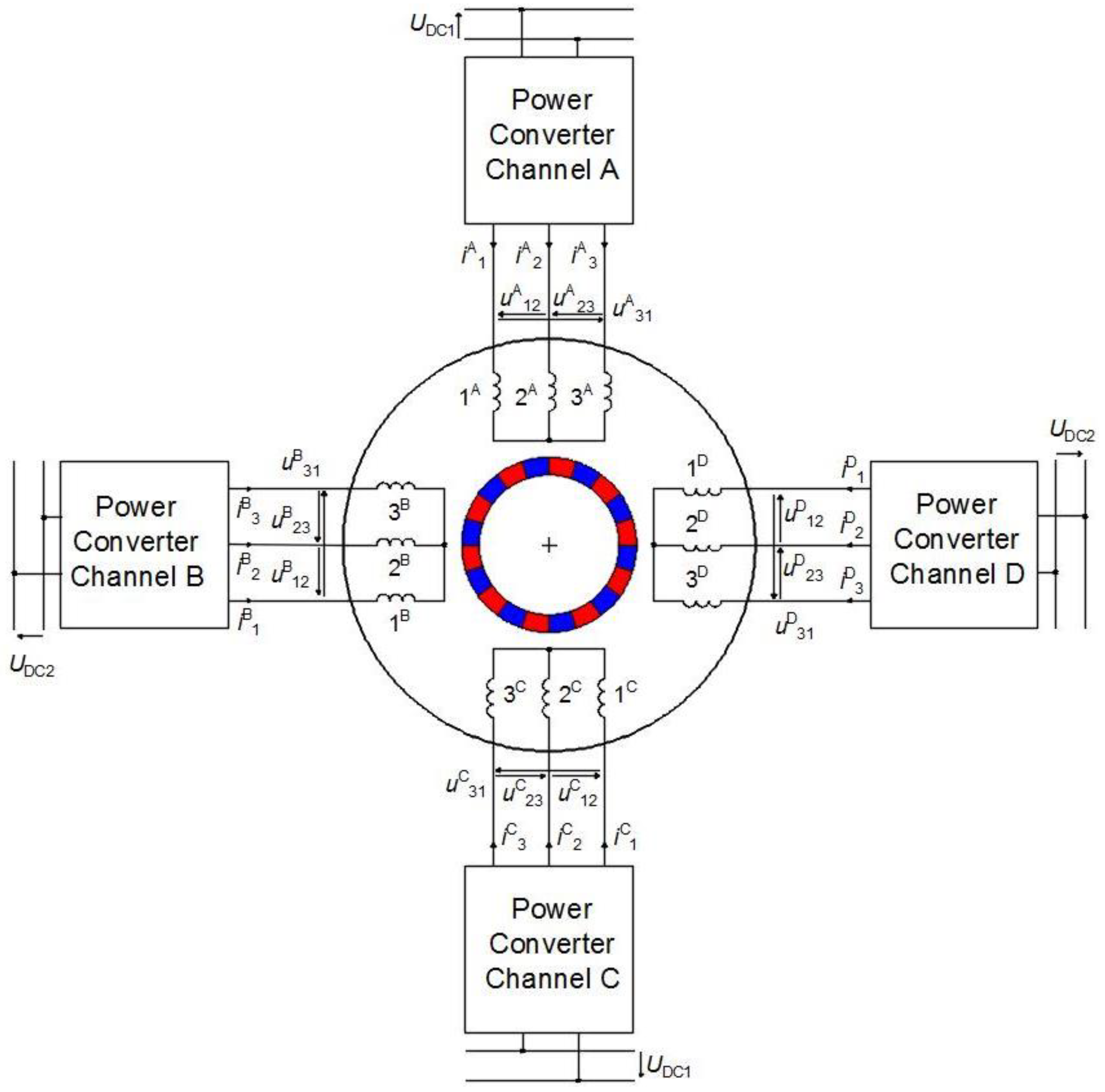
This article analyzes the problem of operating a quad-channel brushless direct current machine with a permanent magnet (QCBLDC) in quad-channel operation (QCO) mode. The four channels of the machine can be supplied from one, two, or four supply sources. An example of supply from two sources (DC1 and DC2) in the QCO mode is shown in
Figure 1.
In the case of an emergency state in one of the channels, the system can switch to operating in the triple-channel operation (TCO) mode, the dual-channel operation (DCO) mode, or the single-channel operation (SCO) mode. This article assumes that a QCBLDC working in the QCO mode, after the occurrence of an emergency state in one of its channels, goes into the DCO mode. The third working channel in this case works as an emergency channel for the DCO mode. In the event of operation in the TCO mode, a balanced magnetic pull can be achieved only for the selected configurations of the channel location. Consequently, this operation status will not be analyzed at this stage of the research. The research problem formulated in this article is an answer to the question: which two channels, out of the three that are not defective, work in the DCO mode? So far, the literature on this topic has not presented an analysis of the properties of a four-channel permanent magnet brushless direct current (QCBLDC) machine, and there is no solution for the aforementioned research problem.
The objective of this article is to present the results of the research conducted by the authors on the properties of a QCBLDC motor working in two modes: QCO and DCO. Knowledge of the results of such an analysis is necessary to prepare a control algorithm that, in the event of the occurrence of an emergency state in one channel, would switch the motor from the QCO mode to the DCO mode. The analysis of the properties of a QCBLDC motor is conducted based on simulations and laboratory tests. Proprietary nonlinear circuit mathematical models for the QCBLDC motor are presented for the QCO and DCO modes. As part of the simulation tests, the results of a finite element method (FEM) two-dimensional analysis of the distribution of the magnetic fluxes and the distribution of stresses on the circumference of the stator are presented. The static characteristics, the current waveforms, and the electromagnetic torque are compared for the operating modes being analyzed. The results of the simulation tests were verified by conducting laboratory tests. The conclusions drawn from the results of the tests are presented in the summary.
2. Model and Winding Configurations of a Quad-Channel BLDC Motor
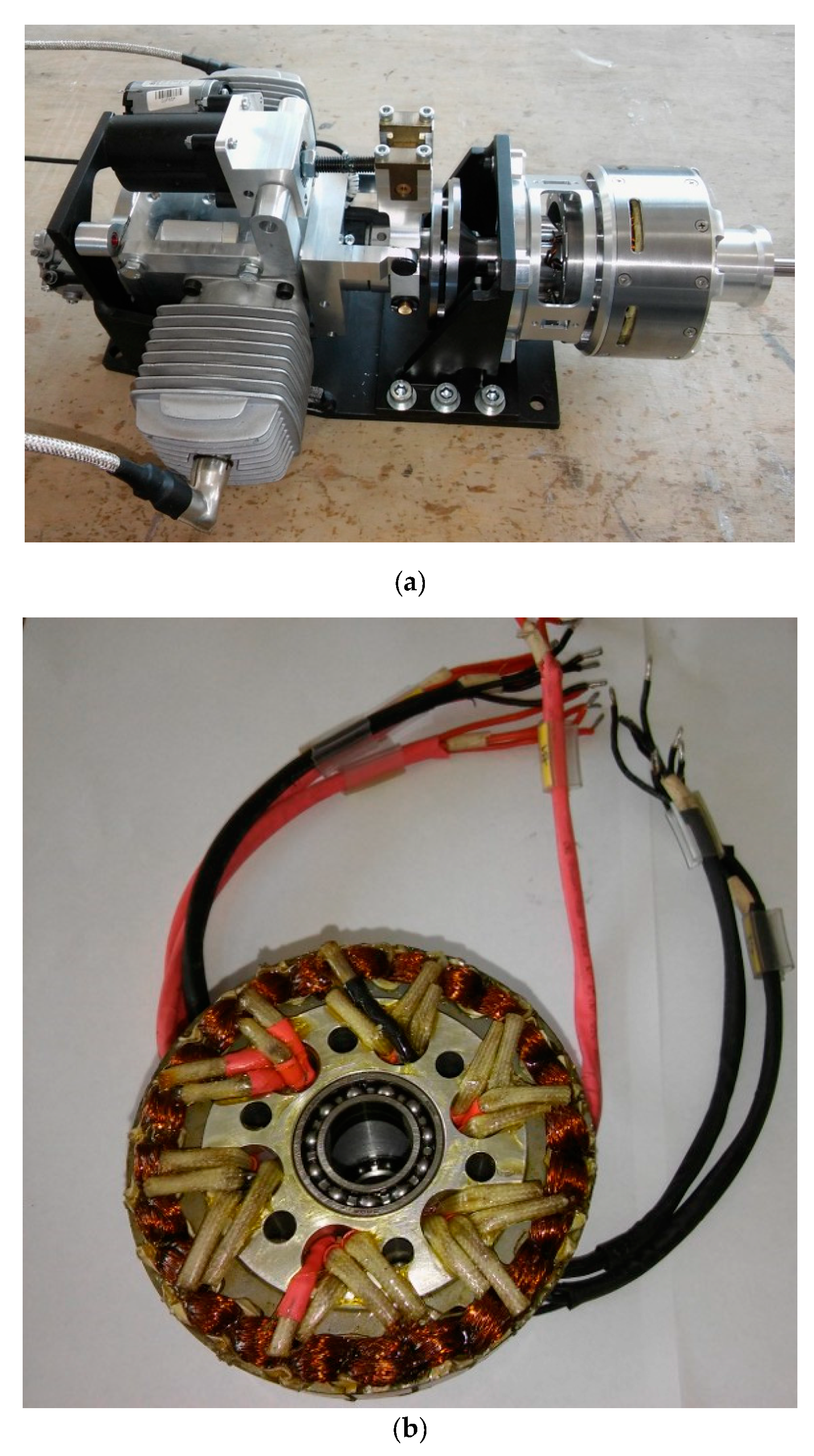
Figure 2a shows a proprietary prototype of the hybrid drive from a small unmanned aerial vehicle (UAV). The electric motor of this object is a three-phase brushless motor with permanent magnets (BLDCM). The stator of the motor with its windings is shown in
Figure 2b. When designing the motor, the possibility to improve the reliability of the drive’s operation is taken into account. The possibility of an independent multi-channel supply for the motor is provided. The tested motor has the possibility to use a quad-channel supply or, as shown in the literature [
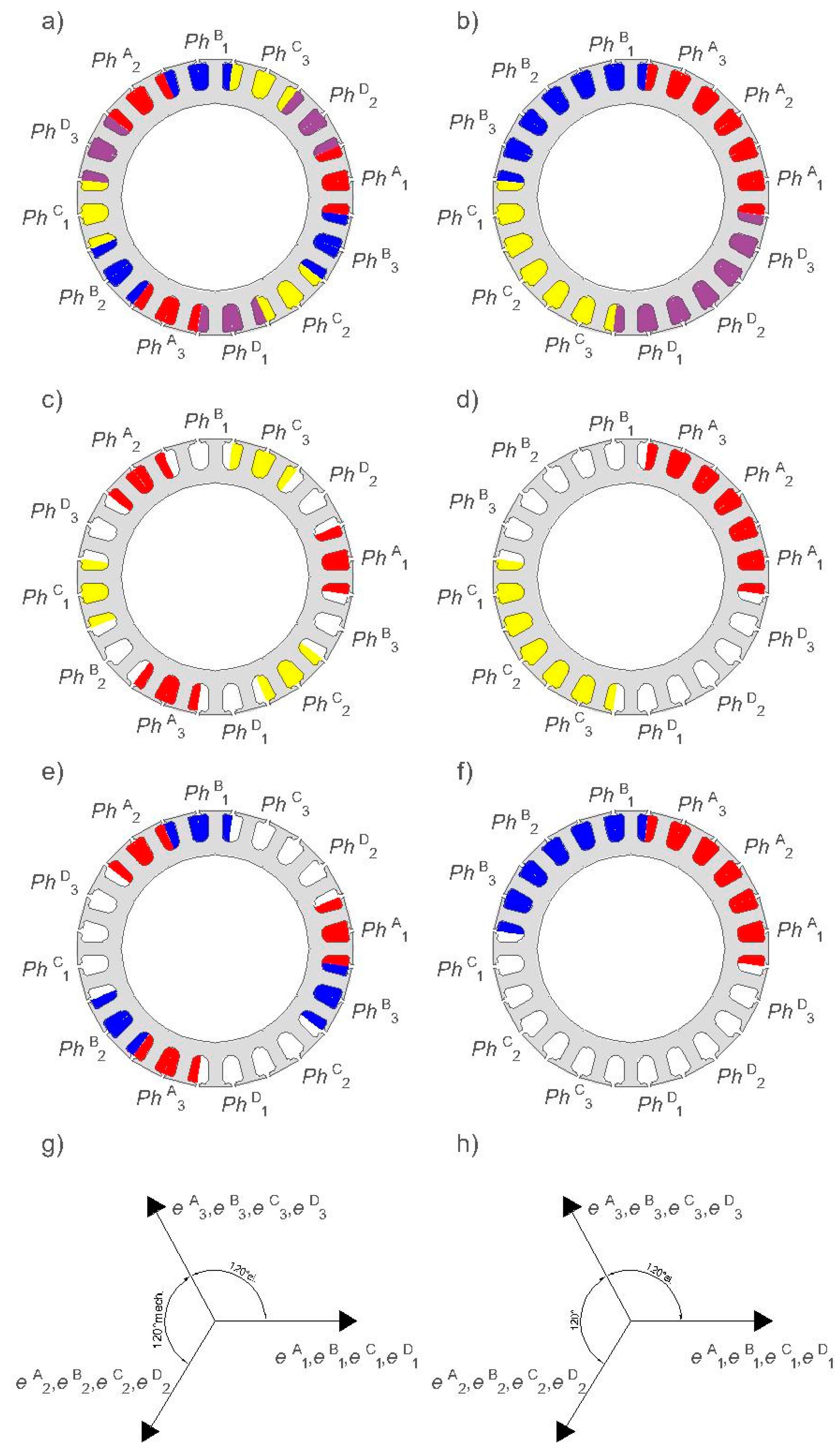
5], a dual-channel supply. In the case of a quad-channel supply, there are two possible configurations of the stator windings. These possibilities are shown in
Figure 3a (variant I) and
Figure 3b (variant II). What makes these configurations different is the location of the windings of the different channels on the circumference of the stator. In variant I, the phases of each channel are staggered by 120 mechanical degrees (
Figure 3a). In variant II, the windings of each channel are staggered by 30 mechanical degrees (
Figure 3b). The channels in both variants are distributed as follows:
Moreover, it was assumed that continuous operation was also possible using only two channels, i.e., in the DCO mode. In this case, the two remaining channels are redundant.
Regardless of the variant, there are six possible configurations of DCO: A and B, A and C, A and D, B and C, B and D, and C and D. In this paper, only two are analyzed; A and B and A and C. This analysis is shown in
Table 1 and
Figure 3c–f.
Figure 3g,h show a phasor diagram of the induced voltages (BEMF) in the windings (1,2,3) of individual channels (A,B,C,D) for variants I and II. At the same time, under the conditions of a fully operational drive, it is possible to use all channels. This operating condition is identified as the QCO (quad-channel operation) mode. In this operating condition, each channel works with half of the required power. When analyzing the multi-channel supply, the impact of the location of the channels and the way they are supplied on the magnetic pull force was not considered. These aspects will be analyzed in subsequent stages of the research based on a coupled electromagnetic-mechanical analysis. Further, operations in odd channel number conditions (i.e., TCO and SCO) are not considered. The TCO mode may occur when one of the channels becomes defective. SCO is a condition of the critical operation of the system. This means that the remaining three channels have already become defective.
3. Mathematical Model of the QCBLDC Motors
The subject of the mathematical modelling is the QCBLDC motor, for which the authors’ circuit-based models, known as flux models, were proposed. The mathematical models are presented while taking into account the non-linearity of the magnetic circuit and the magnetic couplings between the particular phases within the given channel, as well as between the channels (A, B, C, D). Models are included for a machine that works in two modes: the quad-channel operation (QCO) mode and the dual-channel operation (DCO) mode.
The following simplifying assumptions have been adopted in the proposed mathematical model of the QCBLDC machine:
1. Symmetry of the magnetic and electric circuit structure of both the stator and rotor;
2. Decomposition of the phase fluxes into a sum of fluxes induced by phase currents (leakage and main fluxes) and fluxes from permanent magnets;
3. Simplified leakage fluxes from currents in the end-turns of windings;
4. Omitting the influence of temperature on the fluxes generated by permanent magnets and stator resistance.
3.1. Model for QCO Mode
The general structure of the mathematical model of the three-phase QCBLDC motor in QCO mode can be written in the following form:
where for channels
, the vectors representing the phase voltages,
, phase currents,
, phase back-EMF voltages,
, the flux linkages caused by the phase winding currents,
, as well as the matrixes of the stator resistances,
, are defined as follows:
The following symbols are used in Equations (1) to (3): θ—rotor angle position, —the rotor angular speed, —the permanent magnet magnetization equivalent current, J—the rotor’s (and load’s) moments of inertia, D—the rotor damping of the viscous friction coefficient, —the load torque, —the total electromagnetic torque.
The phase back-EMF vectors in Equation (1) for channels
are defined as follows:
where
for
are the permanent magnet fluxes linking the stator windings. The permanent magnet flux linking each stator winding of the QCBLDC motor follows the trapezoidal profile back-EMF. The real back-EMF is not a flat and ideal trapezoidal waveform. Other real back-EMF profiles can be defined in Equation (1). For example, the back-EMF waveform in the Fourier series for
and
is represented as
The flux linkages caused by the phase winding currents in Equation (1) for
can be written in the following form:
where
is the stator channel index,
is the stator phase number, and
are the coefficients of the end-turn self-inductances. The stator flux linking (the so-called self-flux)
i-th
phase for the k-th channel
in Equation (6) is calculated based on the following dependencies:
From non-linear dependence (Equation (7)), the phase current,
, is calculated:
The electromagnetic torque in Equation (2) can be calculated as a derivative of the total magnetic field co-energy in the air gap with respect to the rotor angle’s position,
θ. The expression
for electromagnetic torque for the QCO mode can be written in the following form:
Electromagnetic torque (Equation (9)) is the sum of the so-called cogging torque,
, torques from fluxes linking permanent magnets and windings currents. The cogging torque of the permanent magnet (PM) machines, produced by magnets, can be expanded into a Fourier series:
where
is the amplitude of the
ν-th harmonic,
q is the number of slots, and
is the initial angle.
The component’s electromagnetic torque produced by the permanent magnets and currents can be acquired in the form:
Equations (1) and (2) with Equations (4), (6), and (9) constitute the nonlinear mathematical model of the QCBLDC motors in the QCO mode.
3.2. Model for DCO Mode
The voltage Equation (1) for the DCO mode, i.e., where only channels A and B are supplied, can be written in the following form:
where, for channels
, the phase back-EMFs voltages,
, and vectors representing the flux linkages caused by phase winding currents,
, are defined as follows:
The expression for the electromagnetic torque,
, with Equation (14) taken into account, can be written in the following form:
The components of the electromagnetic torque produced by permanent magnets and currents (the first component of the right side of Equation (15)) can be determined in the form:
Equation (12) with Equations (13) and (14), and Equation (2) with Equation (15) constitute the mathematical model of a QCBLDC machine in the DCO mode.
4. Static Characteristics
The following assumptions were made in the FEM two-dimensional numerical calculations:
1. Symmetry of the magnetic and electric circuit structure of both the stator and the rotor;
2. Omitting the influence of temperature on fluxes generated by permanent magnets;
3. Omitting the influence of temperature on phase resistance;
4. Maintaining a constant speed in the transient analysis.
4.1. Electromagnetic Torque
The characteristics of static electromagnetic torque were determined for the QCO operation, and for both the analyzed variants (variant I and variant II) of the DCO operation, using FEM two dimensional commercial software [
19].
The calculations were performed for one electrical period (36 mechanical degrees) at
I = constant, supplying the phases,
Ph1 and
Ph2, and speed,
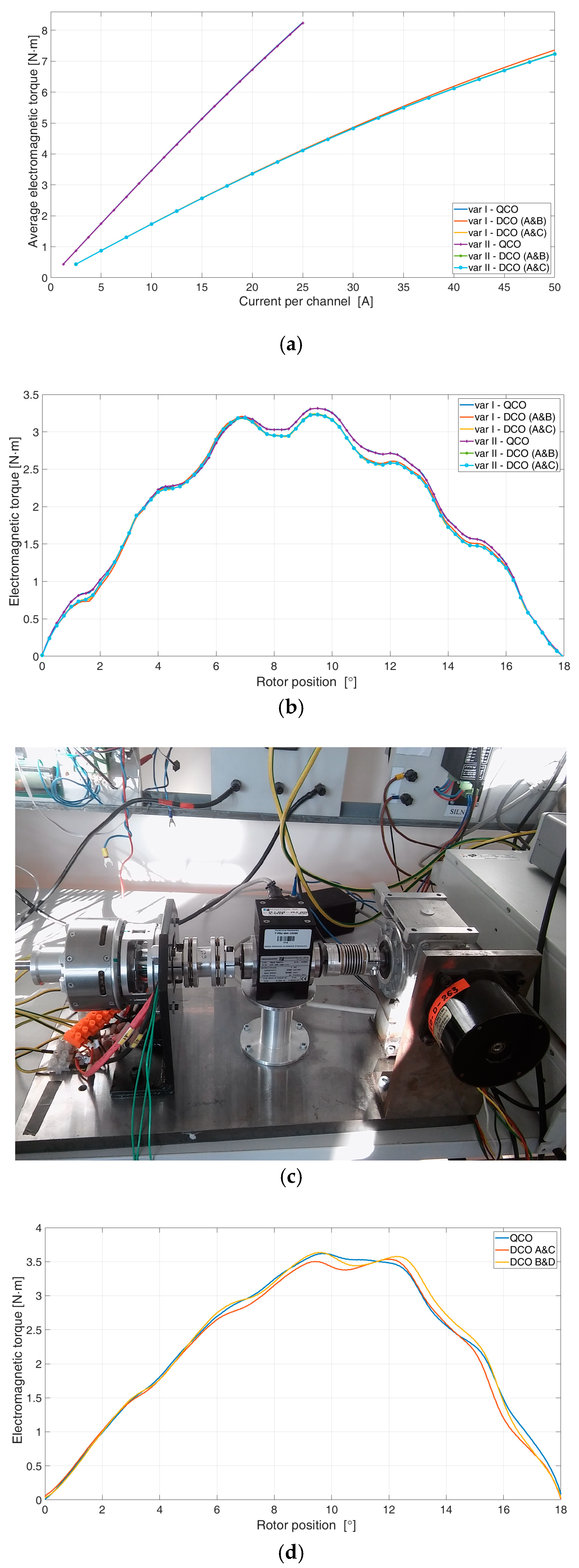
n = 0.167 r/min. The current was changed in the range of 0 to 25 A for QCO and 0 to 50 A for DCO. The average value of the electromagnetic torque,
Teav, as a function of the current,
I, flowing in the channel is shown in
Figure 4a. Examples of the relationship between the electromagnetic torque,
Te, and the rotor position are shown in
Figure 4b. The numerical calculations were verified under laboratory conditions. A laboratory stand used to determine static characteristics is shown in
Figure 4c. Examples of laboratory static torque characteristics are shown in
Figure 4d.
In QCO operation, the configuration type (variant I, variant II) is completely unimportant. In DCO operation, the electromagnetic torque decreases (as a result of saturation). In the operating range (to the value of the rated torque), this influence is practically negligible. In overload operation (or in emergency operation), the constant torque in the DCO mode decreases. The difference between variant I and variant II is insignificant. A slightly smaller value of torque was generated in variant II. In both variants, no difference between the A and B configuration and the A and C configuration was identified in the DCO operation. This means that the type of variant and the configuration does not influence the value of the electromagnetic torque produced. There are differences between the QCO mode and the DCO mode in the stress within the magnetic circuit of the stator.
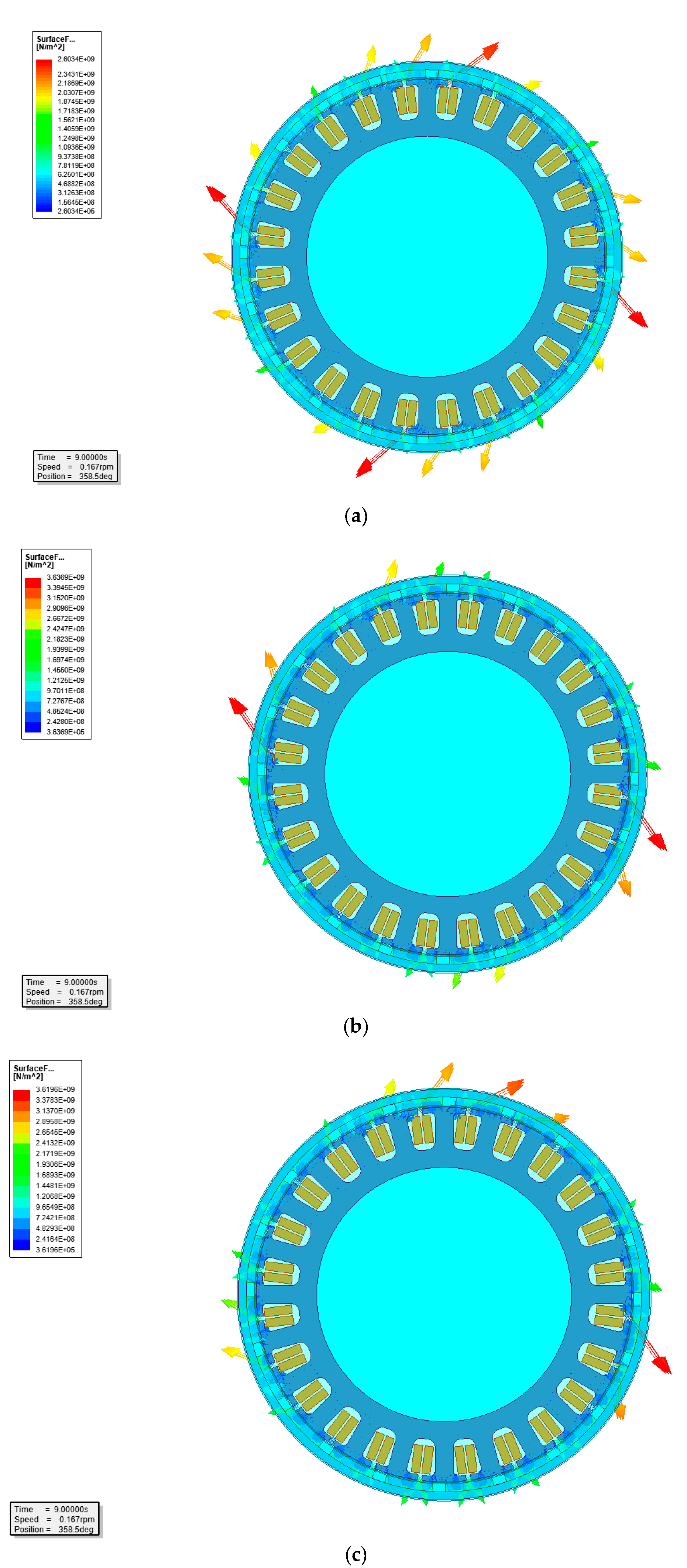
Figure 5 shows examples of the surface force density of the magnetic circuit of the stator (of magnetic origin) for the selected positions of the rotor and for variant I of the stator winding. The results obtained for variant II are similar.
In the DCO mode, there is a significant increase in the stress compared to the QCO mode. In the case of the DCO A and B supply, the distribution of the stresses is non-symmetric, which is conducive to the occurrence of vibrations in the structure. In this regard, this configuration is not recommended. However, if operation needs to continue, e.g., after the C and D channels have become defective, the motor can continue to operate with increased asymmetry of the magnetic pull.
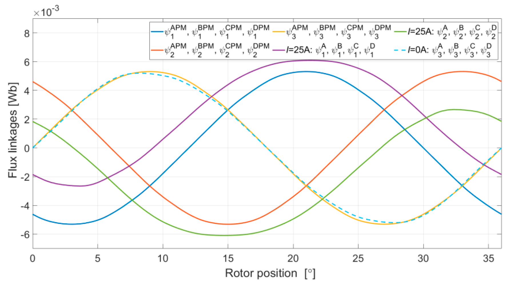
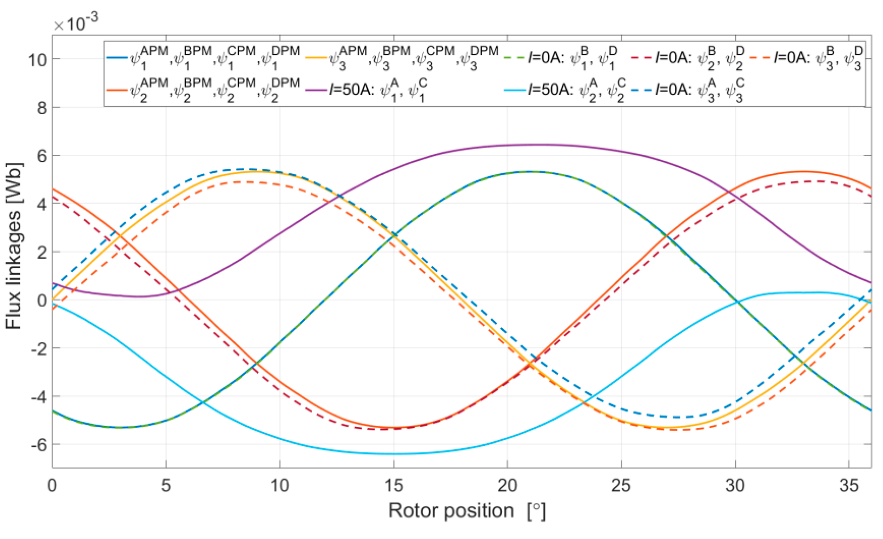
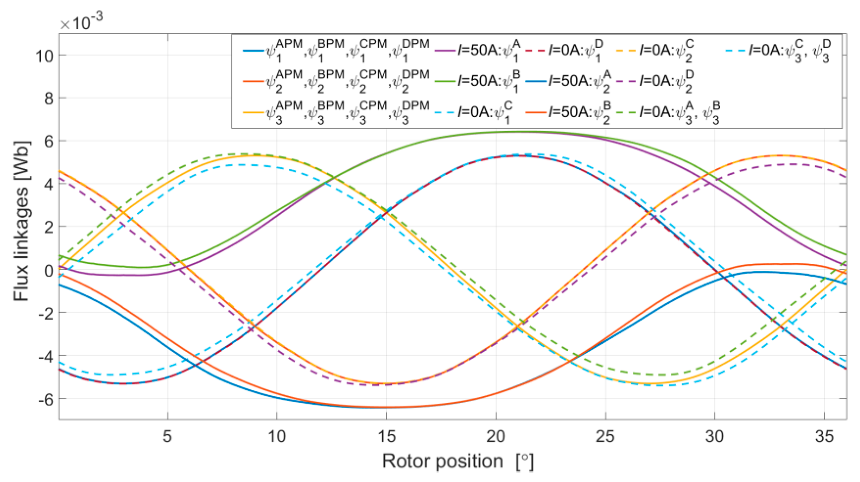
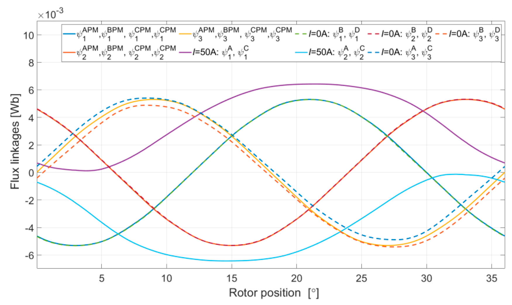
4.2. Flux Characteristics-Variant I
Due to the division of the windings into four channels, there are twelve flux linkages with individual phases.
Figure 6,
Figure 7 and
Figure 8 show the flux linkages as a function of the rotor position for variant I in all analyzed configurations.
In the case of the dual-channel supply in variant I, the A and C supply configuration (
Figure 7) is more beneficial because of its minimal multi-channel magnetic coupling. The A and B configuration has a slightly greater magnetic coupling between the channels. However, the difference is not significant.
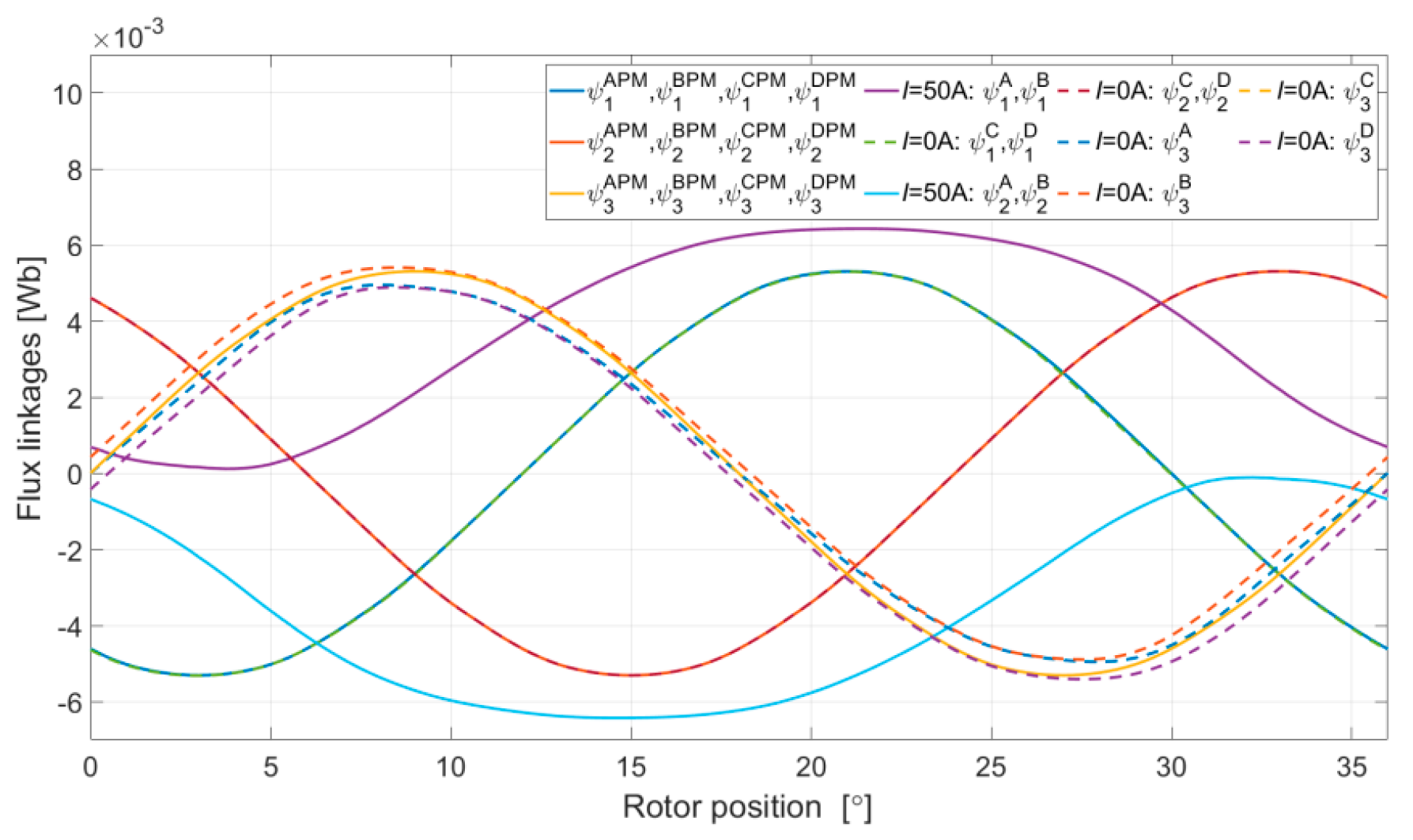
4.3. Flux Characteristics-Variant II
Figure 9 and
Figure 10 show the flux linkages for the analyzed configurations for variant II of the dual-channel supply.
In the case of variant II, it is not possible to indicate a more advantageous configuration due to the impact of the linkages or the impact of saturation of the magnetic circuit.
All determined characteristics were implemented in the simulation model as per the two-dimensional lookup table in the Matlab SISOTOOL system (R2019a, MathWorks, Natick, MA, USA) [
20]. This has been explained in a previous paper [
21].
5. Waveforms, Current, Voltage, and Electromagnetic Torque
5.1. Numerical Calculations
For the purpose of transient analysis, numerical calculations were performed for a constant rotor speed of
n = 1000 r/min. In the calculations, it was assumed that, in the QCO mode, the value of the reference current set on the current control devices in all channels was equal to 10 A. In the dual-channel operation mode, the reference current was equal to 20 A for each of the analyzed configurations of both variants.
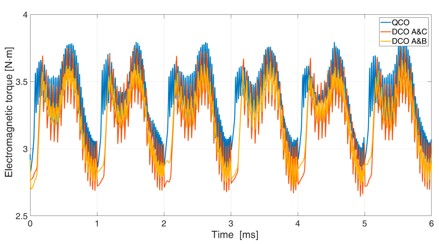
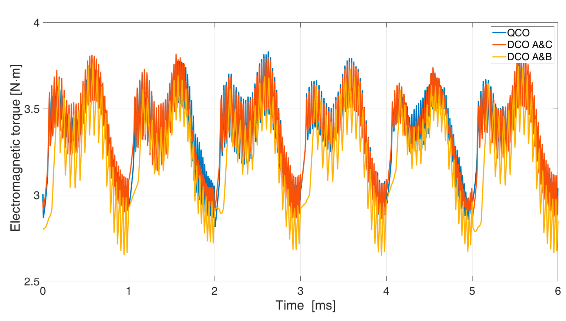
Figure 11 and
Figure 12 show the electromagnetic torque of the motor for variant I (
Figure 11) and variant II (
Figure 12).
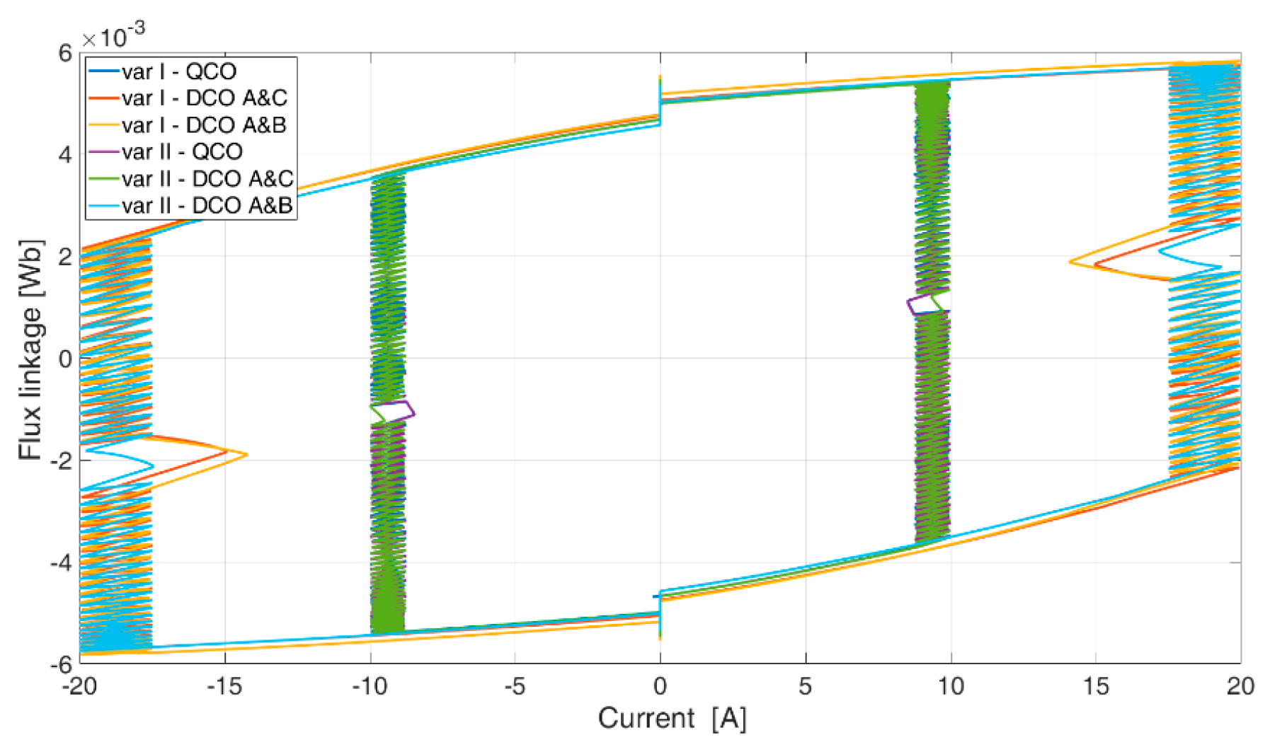
Figure 13 shows the relationship between the flux linkage of the phase,
Ph1, and the current for all cases analyzed.
Selected results of the examinations are presented in
Table 2.
The variant types and configurations of the channels have little impact on the average value of the electromagnetic moment, Teav. Switching to the DCO mode results in an increase in copper losses (Pcu), with a small reduction of iron losses (PFe). In the case of dual-channel operation, the electromagnetic torque’s ripple increases slightly. The efficiency of energy processing in the DCO mode is significantly deteriorated due to increased winding losses. The highest efficiency in the DCO mode was achieved for variant I of A and C. However, in general, the differences in the energy processing efficiency for each of the two variants of the DCO mode are small.
5.2. Laboratory Test
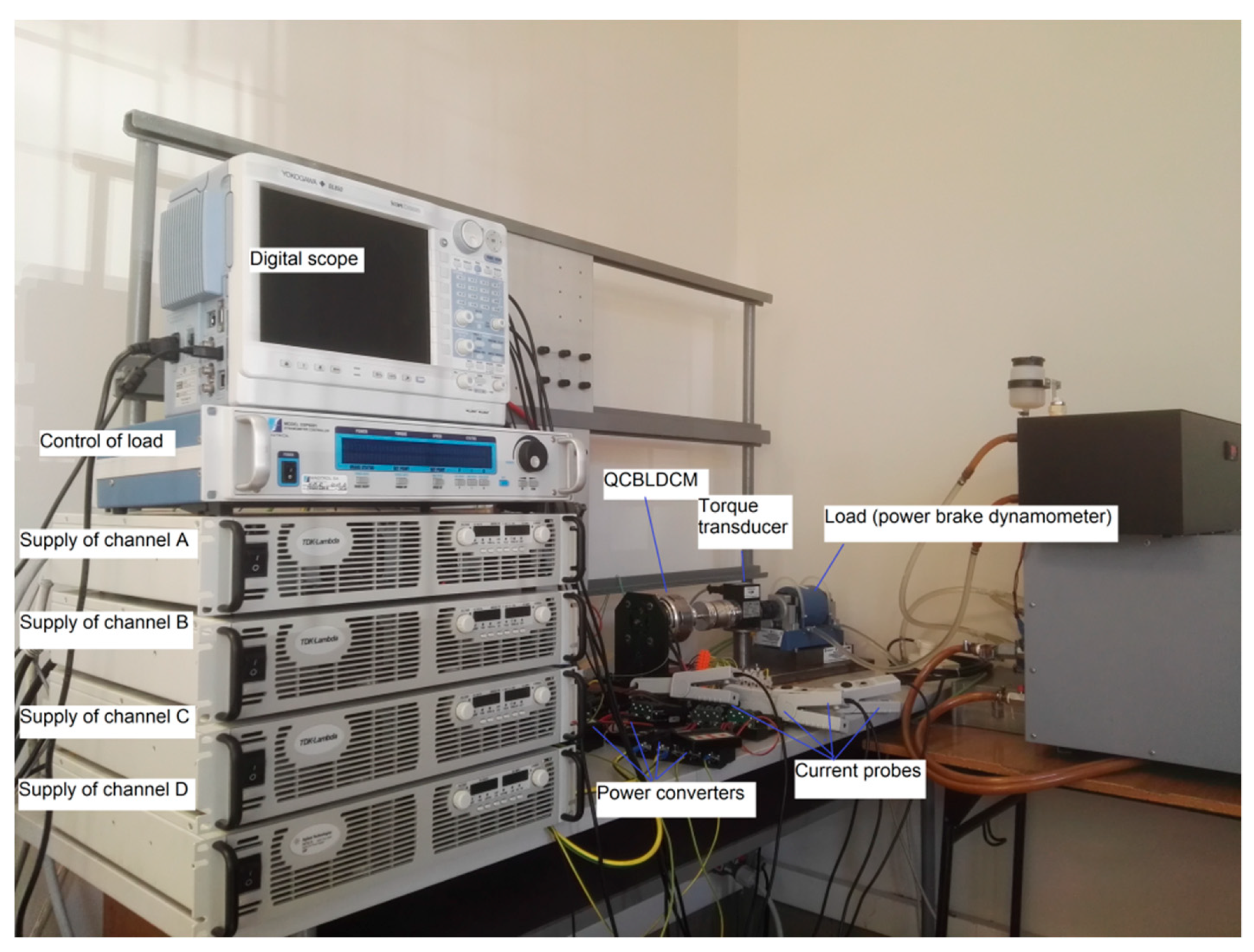
In laboratory conditions, a quad-channel supply for a QCBLDC motor was developed.
Figure 14 shows the test stand. Laboratory tests were performed only for variant II.
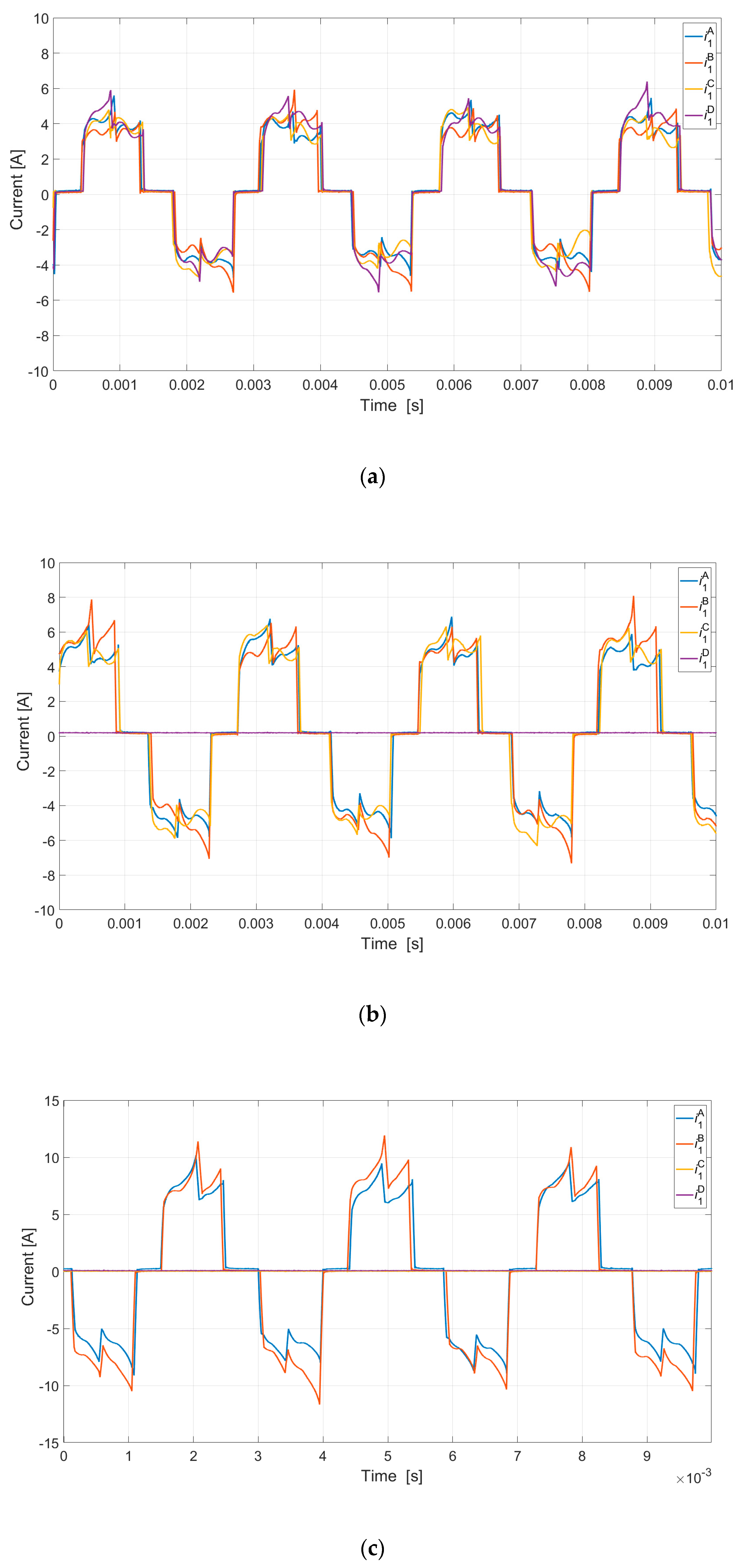
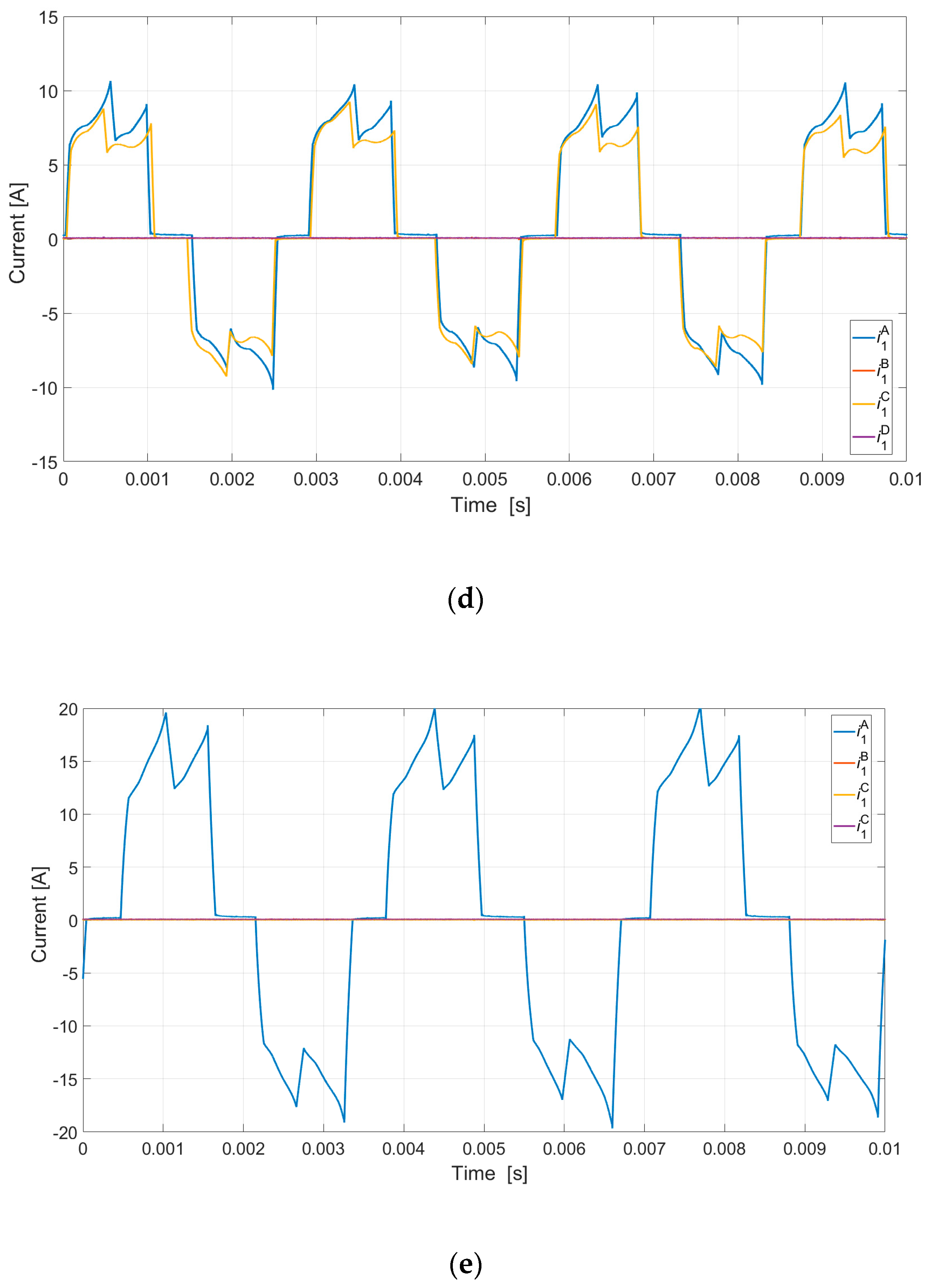
In laboratory conditions, the current waveforms were recorded during quad-channel, triple-channel, dual-channel, and single-channel operations (
Figure 15): A switch from the QCO mode was connected to the TCO mode (
Figure 16a), the DCO A and B mode (
Figure 16b), the DCO A and C mode (
Figure 16c), and to the SCO mode (
Figure 16d) of variant II (
Udc = 24 V,
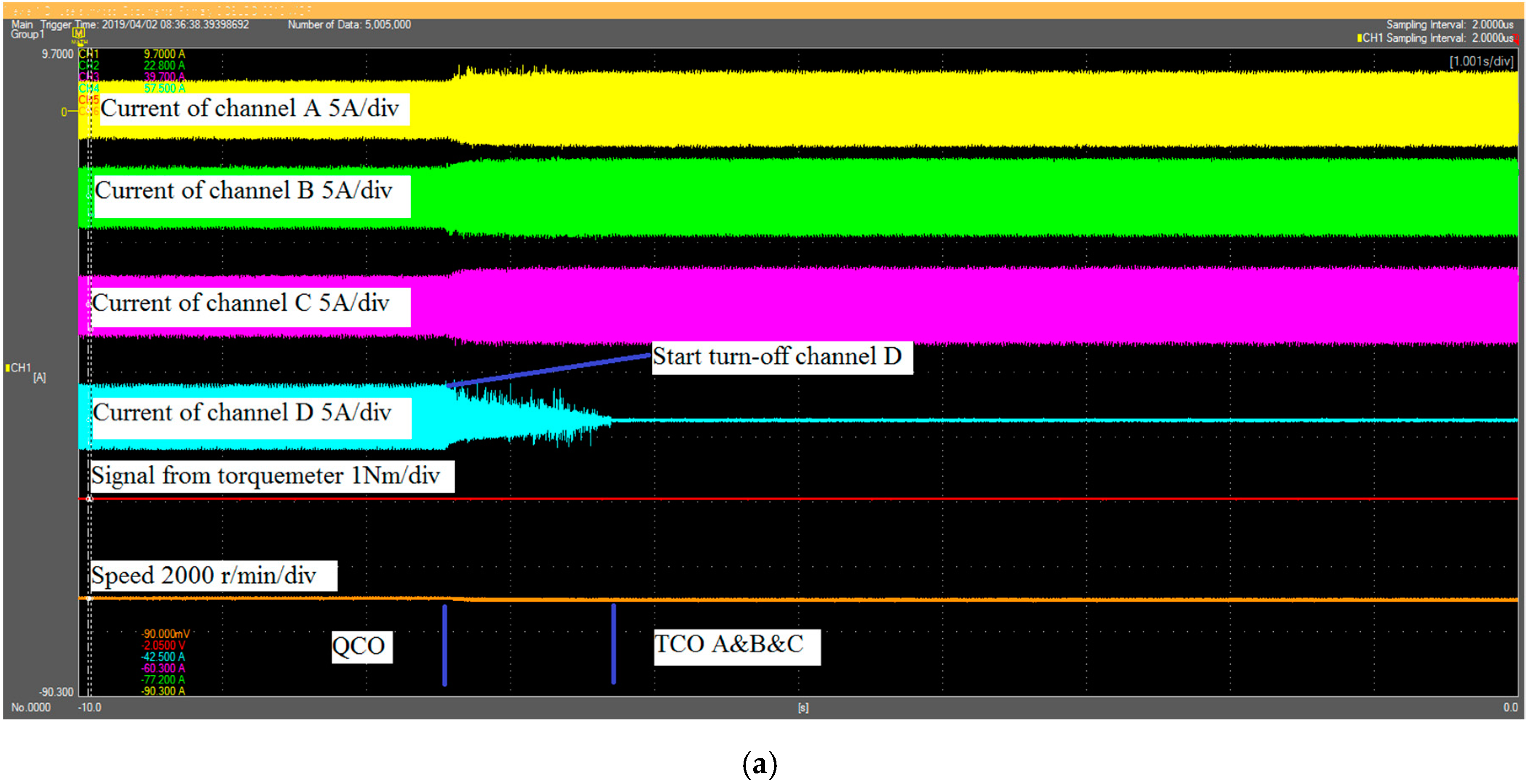
TL = 1.2 N·m).
During the transition from the QCO mode to the TCO, DCO, and SCO modes, channel D (
Figure 16a), C and D (
Figure 16b), B and D (
Figure 16c), and A and B and C (
Figure 16d) were disconnected, and channel A and B and C (
Figure 16a), A and B (
Figure 16b), A and C (
Figure 16c), and D (
Figure 16d) started to operate with a shaft load. To achieve the same moment, the currents in the active channels must increase by 133% in the TCO mode, by 200% in the DCO mode, and by 400% in the SCO mode. This increase leads to a decrease in speed in an open-loop control system and results in an output power decrease of a few percent.
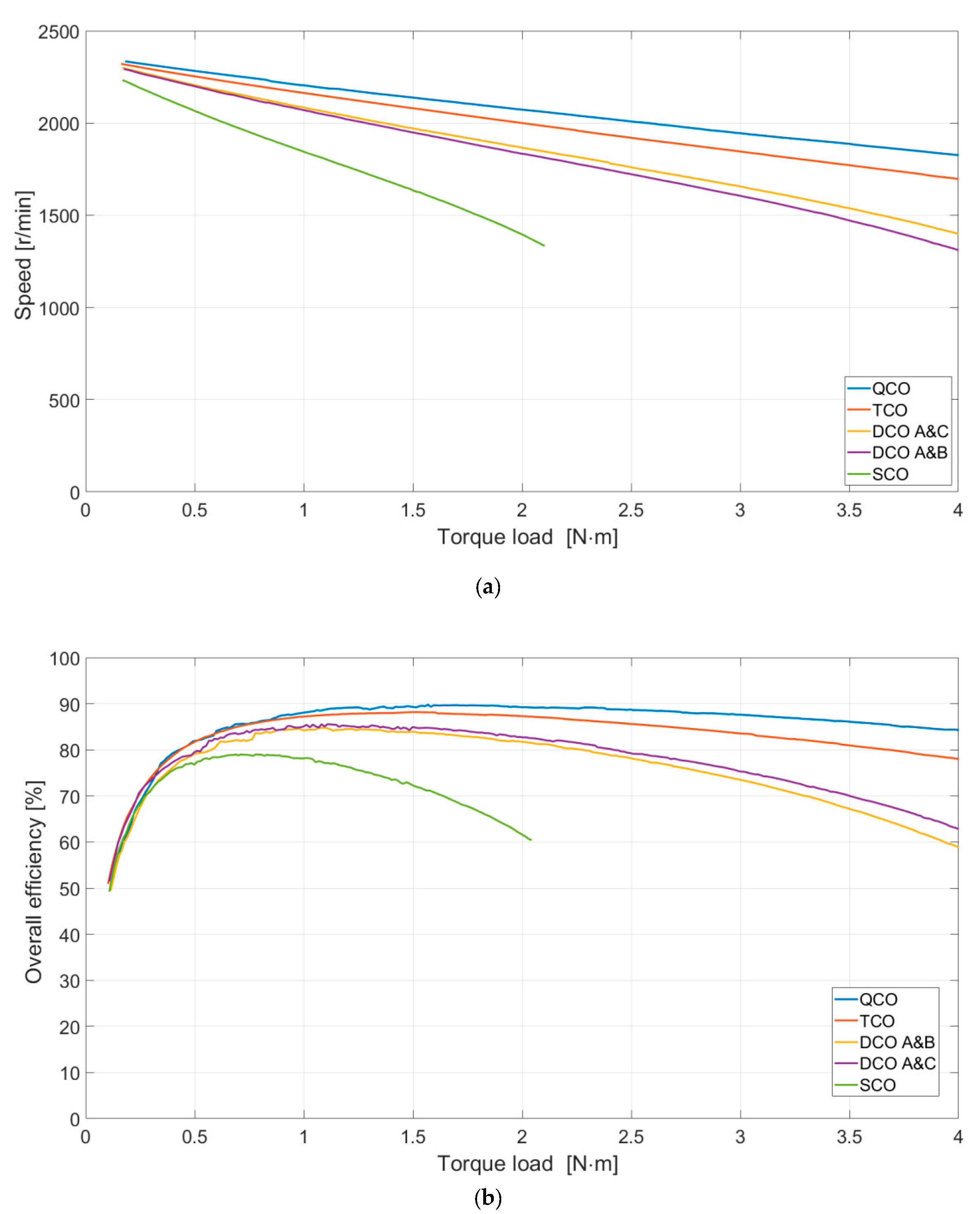
The mechanical characteristics and the general efficiency were determined for the selected work mode in a stable state (without current regulation). The load torque was changed to 4 N·m (or 2 N·m for the SCO mode). The rotational speed as a function of the load torque is shown in
Figure 17a. The general efficiency as a function of the load torque is shown in
Figure 17b. This was determined using the direct method (
η =
Pout/
Pin). For a load torque of
TL = 2 N·m, the acceleration of vibration and the noise level were recorded. The results are given in
Table 3.
The QCO, TCO, and DCO work modes enable continuous operation of the machine. In the case of the SCO mode, the motor is usually already working in the overload range. This is a critical work condition that should enable operation of the device for a specific period of time. The QCO mode ensures the highest efficiency. In the TCO mode, the efficiency of energy processing is slightly reduced. In the DCO mode, a slightly higher efficiency is achieved in the A and C mode. This efficiency is smaller than that in the TCO mode.
The vibration and noise results presented in
Table 3 indicate that the most advantageous work mode is QCO. The DCO A and C work condition was only slightly worse than QCO. The TCO work mode (regardless of the variant) was noticeably noisier than the DCO A and C mode. The DCO A and B work mode was significantly noisier than The DCO A and C mode and TCO mode. The SCO mode was comparable to the DCO A and B mode.
It is possible to maintain a constant speed after turning off one, two, or three channels under operation in a constant torque region.
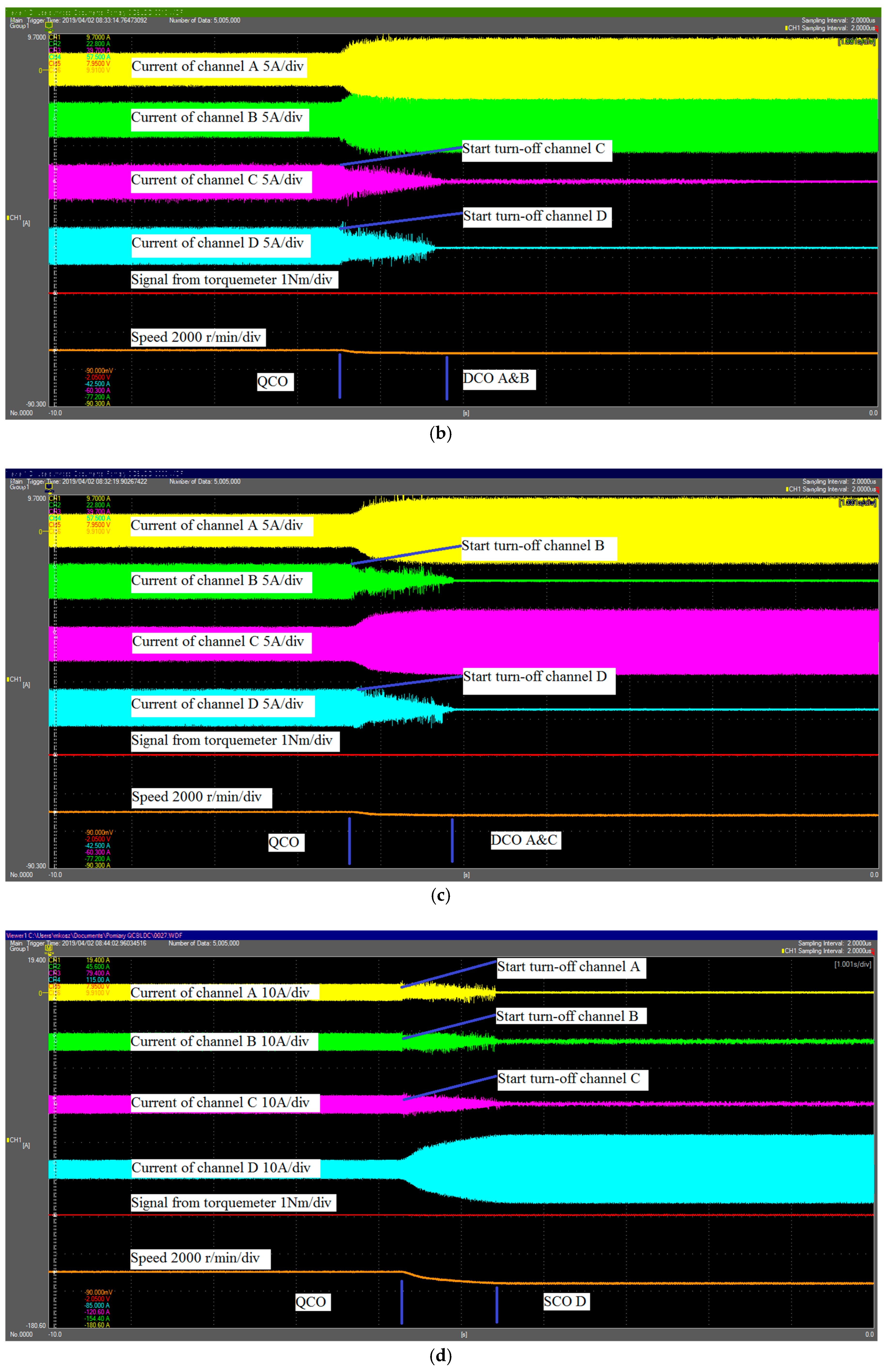
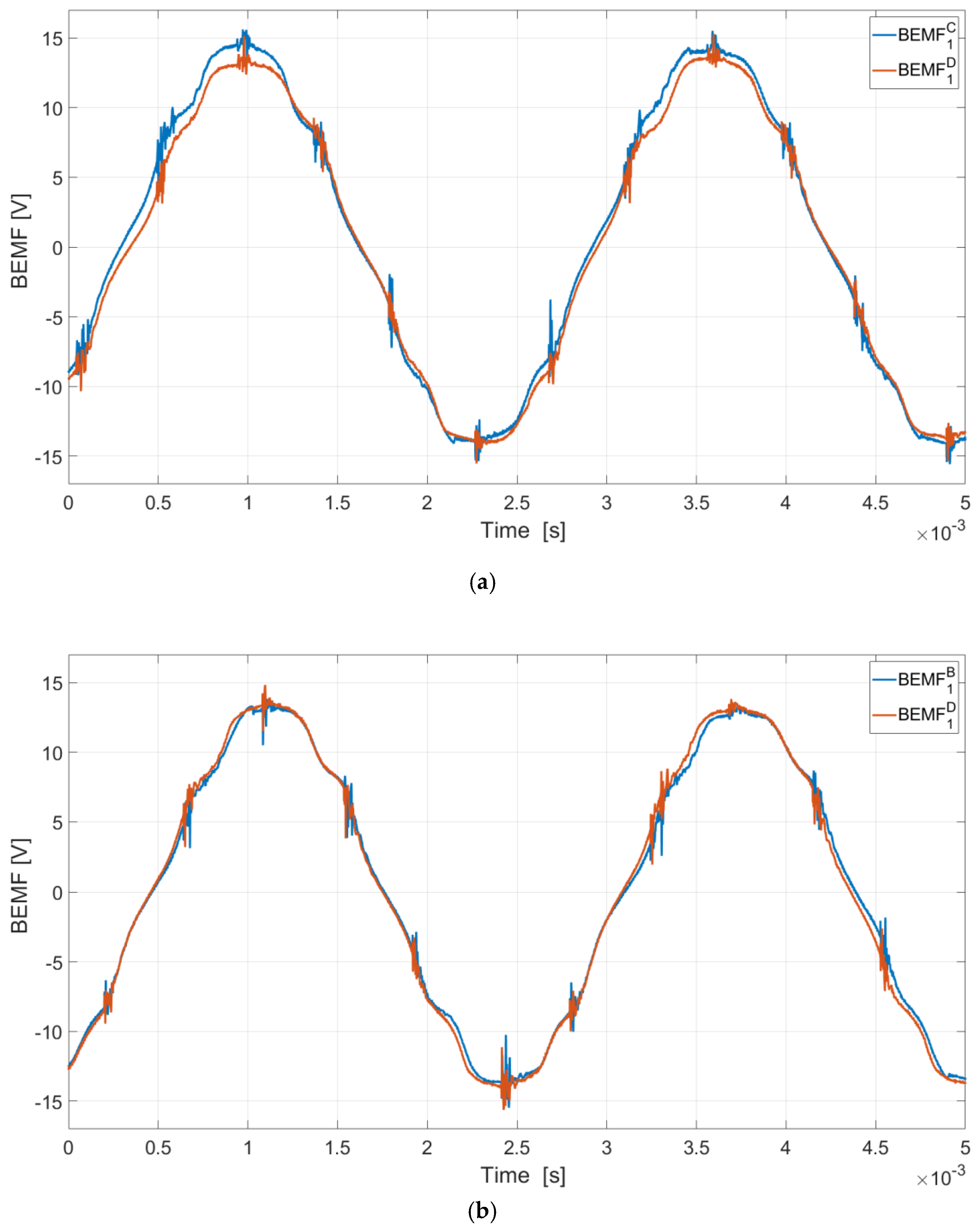
In a practical layout, some differences between the channels were visible (
Figure 15a–c). These differences are due to the differences between the voltages induced in the windings of the different channels. The induced voltages (BEMF) of the shut-down channels in the DCO of one phase are shown in
Figure 18. These differences do not affect the reliability of the machine but, unfortunately, result in uneven loads on different channels.
The problem of operating in TCO, DCO, and SCO modes after the occurrence of a fault state (e.g., short-circuit in the winding) was initially analyzed. Under certain conditions, further motor operation is possible. This was confirmed by preliminary laboratory tests. This will be discussed in future publications.
6. Conclusions
Reliable operation is vitally important for critical drives. This article proposes a quad-channel design for a BLDC machine (QCBLDC) that allows operation with an independent supply from four inverter systems. During fault-free operation, this machine can work in one of the following two operating modes: quad-channel operation (QCO) or dual-channel operation (DCO). In the DCO mode, there are two possible configurations, which are not significantly different from each other with regards to their electrical parameters. The two variants analyzed in this article have very similar parameters. For mechanical reasons, it is more beneficial to supply channel windings staggered by 120 mechanical degrees (variant I). For technological reasons, it is easier to manufacture variant II (shorter winding connections). Compared to the QCO mode, the DCO mode for the same duty point is characterized by a slightly lower efficiency (greater copper losses) and only a slightly higher but balanced magnetic pull (A and C mode). In the case of the DCO A and C mode, the type of variant is not important. In the case of the DCO A and B variant II, a significant increase in vibrations and noise was observed. In the case of variant II of the TCO mode, there was also an insignificant (but noticeable) increase in the vibration and noise level compared to DCO A and C. The results of both the simulation tests and the laboratory tests confirm that the suggested design for the QCBLDC motor effectively works in both the QCO and DCO modes. The problem of operating in TCO, DCO, and SCO modes after the occurrence of a fault state, and the preparation of control algorithms that will facilitate the continued operation of a QCBLDC machine in such a situation, will be discussed in future publications.
Author Contributions
Conceptualization, J.P. and M.K.; methodology, J.P. and M.K.; software, M.K.; formal analysis, J.P. and M.K.; investigation, J.P.; resources, M.K.; writing—original draft preparation, M.K.; writing—review and editing, J.P. and P.B.; visualization, M.K.; supervision, J.P.; project administration, M.K.; funding acquisition, M.K.
Funding
This work is financed in part by the statutory funds of the Department of Electrodynamics and Electrical Machine Systems, Rzeszow University of Technology and in part by the Polish Ministry of Science and Higher Education under the program “Regional Initiative of Excellence” in 2019–2022. Project number 027/RID/2018/19, amount granted 11,999,900 PLN.
Conflicts of Interest
The authors declare no conflict of interest.
References
- Cao, W.; Mecrow, B.C.; Atkinson, G.J.; Bennett, J.W.; Atkinson, D.J. Overview of Electric Motor Technologies Used for More Electric Aircraft (MEA). IEEE Trans. Ind. Electron. 2012, 59, 3523–3531. [Google Scholar]
- Zhang, G.; Zhang, H.; Huang, X.; Wang, J.; Yu, H.; Graaf, R. Active Fault-Tolerant Control for Electric Vehicles With Independently Driven Rear In-Wheel Motors Against Certain Actuator Faults. IEEE Trans. Control Syst. Technol. 2016, 24, 1557–1572. [Google Scholar] [CrossRef]
- Nounou, K.; Charpentier, J.F.; Marouani, K.; Benbouzid, M.; Kheloui, A. Emulation of an Electric Naval Propulsion System Based on a Multiphase Machine under Healthy and Faulty Operating Conditions. IEEE Trans. Veh. Technol. 2018, 67, 6895–6905. [Google Scholar] [CrossRef]
- Kwon, S.; Ha, J. Fault-tolerant operation with 1-phase open in parallel-connected motor. In Proceedings of the IEEE Applied Power Electronics Conference and Exposition (APEC), San Antonio, TX, USA, 4–8 March 2018. [Google Scholar]
- Vaidya, J.G. Redundant Multiple Channel Electric Motors and Generators. United States Patent Number 4550267A, 29 October 1985. [Google Scholar]
- Targo, B.A.; Lordo, R.E. Fault Tolerant Electric Machine. United States Patent Number 5929549A, 27 July 1999. [Google Scholar]
- Korkosz, M.; Bogusz, P.; Prokop, J. Modelling and experimental research of fault-tolerant dual-channel brushless DC motor. IET Electr. Power Appl. 2018, 12, 787–796. [Google Scholar] [CrossRef]
- Ding, W.; Liang, D. Comparison of transient and steady-state performances analysis for a dual-channel switched reluctance machine operation under different modes. IET Electr. Power Appl. 2010, 4, 603–617. [Google Scholar] [CrossRef]
- Arafat, A.K.M.; Choi, S. Optimal Phase Advance Under Fault-Tolerant Control of a Five-Phase Permanent Magnet Assisted Synchronous Reluctance Motor. IEEE Trans. Ind. Electron. 2018, 65, 2915–2924. [Google Scholar] [CrossRef]
- Levi, E.; Bojoi, R.; Profumo, F.; Toliyat, H.A.; Williamson, S. Multiphase induction motor drives—A technology status review. IET Electr. Power Appl. 2007, 1, 489–516. [Google Scholar] [CrossRef]
- Bojoi, R.; Cavagnino, A.; Tenconi, A.; Vaschetto, S. Control of Shaft-Line-Embedded Multiphase Starter/Generator for Aero-Engine. IEEE Trans. Ind. Electron. 2016, 63, 641–652. [Google Scholar] [CrossRef]
- Popescu, M.; Dorrell, D.G.; Alberti, L.; Bianchi, N.; Staton, D.A.; Hawkins, D. Thermal Analysis of Duplex Three-Phase Induction Motor Under Fault Operating Conditions. IEEE Trans. Ind. Appl. 2013, 49, 1523–1530. [Google Scholar] [CrossRef]
- Umesh, B.S.; Sivakumar, K. Dual-Inverter-Fed Pole-Phase Modulated Nine-Phase Induction Motor Drive With Improved Performance. IEEE Trans. Ind. Electron. 2016, 63, 5376–5383. [Google Scholar] [CrossRef]
- Ullah, S.; McDonald, S.P.; Martin, R.; Benarous, M.; Atkinso, G.J. A Permanent Magnet Assist, Segmented Rotor, Switched Reluctance Drive for Fault Tolerant Aerospace Applications. IEEE Trans. Ind. Appl. 2019, 55, 298–305. [Google Scholar] [CrossRef]
- Wang, B.; Wang, J.; Griffo, A.; Shi, Y. Investigation Into Fault-Tolerant Capability of a Triple Redundant PMA SynRM Drive. IEEE Trans. Power Electron. 2019, 34, 1611–1621. [Google Scholar] [CrossRef]
- Jiang, X.; Huang, W.; Cao, R.; Hao, Z.; Li, J.; Jiang, W. Electric Drive System of Dual-Winding Fault-Tolerant Permanent-Magnet Motor for Aerospace Applications. IEEE Trans. Ind. Electron. 2015, 62, 7322–7330. [Google Scholar] [CrossRef]
- Guo, H.; Xu, J.; Chen, Y. Robust Control of Fault-Tolerant Permanent-Magnet Synchronous Motor for Aerospace Application with Guaranteed Fault Switch Process. IEEE Trans. Ind. Electron. 2015, 62, 7309–7321. [Google Scholar] [CrossRef]
- Li, H.; Li, W.; Ren, H. Fault-Tolerant Inverter for High-Speed Low-Inductance BLDC Drives in Aerospace Applications. IEEE Trans. Power Electron. 2017, 32, 2452–2463. [Google Scholar] [CrossRef]
- ANSYS. Ansys Electronics Release 2019 R1; ANSYS Inc.: Canonsburg, PA, USA, 2019. [Google Scholar]
- MathWorks. MATLAB R2019a; The MathWorks Inc.: Natick, MA, USA, 2019. [Google Scholar]
- Bogusz, P.; Korkosz, M.; Prokop, J. The analysis of flux characteristics of dual-channel BLDC machine. In Proceedings of the 2017 International Symposium on Electrical Machines (SME), Naleczow, Poland, 18–21 June 2017. [Google Scholar]
Figure 1.
A scheme of a quad-channel brushless permanent magnet direct current (QCBLDC) supply system under quad-channel operation (QCO) mode with two supply sources.
Figure 1.
A scheme of a quad-channel brushless permanent magnet direct current (QCBLDC) supply system under quad-channel operation (QCO) mode with two supply sources.
Figure 2.
The prototype of a three-phase quad-channel brushless machine with a permanent magnet (QCBLDC) machine; (a) the hybrid drive of a small unmanned aerial vehicle; (b) the stator with windings.
Figure 2.
The prototype of a three-phase quad-channel brushless machine with a permanent magnet (QCBLDC) machine; (a) the hybrid drive of a small unmanned aerial vehicle; (b) the stator with windings.
Figure 3.
Scheme of the winding distribution of channels on the stator of a three-phase QCBLDC motor: variant I—quad-channel operation (QCO) (a), variant II—QCO (b), variant I—dual-channel operation (DCO) (channel A and C) (c), variant II—DCO (channel A and C) (d), variant I—DCO (channel A and B) (e), variant II—DCO (channel A and B) (f), variant I—phasor diagram (g), and variant II—phasor diagram (h).
Figure 4.
The static characteristics of electromagnetic torque: The average value of electromagnetic torque vs. current (a); electromagnetic torque vs. rotor positions—simulation tests (b); the stand to determine static characteristics (c); electromagnetic torque vs. rotor positions (laboratory test—variant II) (d).
Figure 5.
Surface force density: QCO (a); DCO A and C (b); DCO A and B (c)—variant I.
Figure 5.
Surface force density: QCO (a); DCO A and C (b); DCO A and B (c)—variant I.
Figure 6.
Flux linkages vs. rotor positions for QCO—variant I.
Figure 6.
Flux linkages vs. rotor positions for QCO—variant I.
Figure 7.
Flux linkages vs. rotor positions for DCO A and C—variant I.
Figure 7.
Flux linkages vs. rotor positions for DCO A and C—variant I.
Figure 8.
Flux linkages vs. rotor positions for DCO A and B—variant I.
Figure 8.
Flux linkages vs. rotor positions for DCO A and B—variant I.
Figure 9.
Flux linkages vs. rotor positions for DCO A and C—variant II.
Figure 9.
Flux linkages vs. rotor positions for DCO A and C—variant II.
Figure 10.
Flux linkages vs. rotor positions for DCO A and B—variant II.
Figure 10.
Flux linkages vs. rotor positions for DCO A and B—variant II.
Figure 11.
Waveforms of electromagnetic torque—variant I.
Figure 11.
Waveforms of electromagnetic torque—variant I.
Figure 12.
Waveforms of electromagnetic torque—variant II.
Figure 12.
Waveforms of electromagnetic torque—variant II.
Figure 13.
Flux linkages vs. rotor positions for all configurations.
Figure 13.
Flux linkages vs. rotor positions for all configurations.
Figure 14.
Stand for transient test of a QCBLDC motor.
Figure 14.
Stand for transient test of a QCBLDC motor.
Figure 15.
Waveforms of currents for QCO (a); TCO (b); DCO A and C (c); DCO A and B (d); and SCO (e).
Figure 15.
Waveforms of currents for QCO (a); TCO (b); DCO A and C (c); DCO A and B (d); and SCO (e).
Figure 16.
Waveforms of the currents, load torque, and speed for QCO in the TCO mode (a), the DCO A and B mode (b), the DCO A and C mode (c), and the SCO mode (d).
Figure 16.
Waveforms of the currents, load torque, and speed for QCO in the TCO mode (a), the DCO A and B mode (b), the DCO A and C mode (c), and the SCO mode (d).
Figure 17.
Speed vs. torque load (a), overall efficiency vs. torque load (b)—variant II.
Figure 17.
Speed vs. torque load (a), overall efficiency vs. torque load (b)—variant II.
Figure 18.
The induced voltages: DCO A and B mode (a), DCO A and C mode (b).
Figure 18.
The induced voltages: DCO A and B mode (a), DCO A and C mode (b).
Table 1.
The selected typical operation conductions of a QCBLDC motor.
Table 1.
The selected typical operation conductions of a QCBLDC motor.
| Channel | Variant I | Variant II |
|---|
| QCO | TCO | DCO | SCO | QCO | TCO | DCO | SCO |
|---|
| A and B | A and C | A and B | A and C |
|---|
| A | X | X | X | X | X | X | X | X | X | X |
| B | X | X | X | - | - | X | X | X | - | - |
| C | X | X | - | X | - | X | X | - | X | - |
| D | X | - | - | - | - | X | - | - | - | - |
Table 2.
The selected results of the calculations for the analyzed operating conditions.
Table 2.
The selected results of the calculations for the analyzed operating conditions.
| Parameter | Variant I | Variant II |
|---|
| QCO | DCO A and C | DCO A and B | QCO | DCO A and C | DCO A and B |
|---|
| Teav [ N⋅m] | 3.35 | 3.21 | 3.21 | 3.35 | 3.21 | 3.21 |
| Torque ripple [%] | 14.5 | 17.7 | 15.6 | 15.2 | 17.7 | 17.3 |
| IArms_av [A] | 7.6 | 14.9 | 14.9 | 7.6 | 15 | 15 |
| IBrms_av [A] | 7.6 | - | 15.1 | 7.6 | - | 15 |
| ICrms_av [A] | 7.6 | 14.9 | - | 7.6 | 15 | - |
| IDrms_av [A] | 7.6 | - | - | 7.6 | - | - |
| PFe [W] | 10.6 | 7.6 | 7.3 | 10.5 | 7.2 | 7.5 |
| Pcu [W] | 48.5 | 93.2 | 94.7 | 48.5 | 94.5 | 94.5 |
| η [%] | 84.5 | 76.0 | 75.9 | 84.5 | 75.9 | 75.6 |
Table 3.
Selected results of the acceleration and the noise level.
Table 3.
Selected results of the acceleration and the noise level.
| Mode | Noise [dB] | Acceleration [m/s2] |
|---|
| QCO | 61.1 | 1.7 |
| TCO | 65.8 | 5.0 |
| DCO A and B | 75.1 | 7.5 |
| DCO A and C | 61.5 | 2.4 |
| SCO | 76.2 | 12.5 |
© 2019 by the authors. Licensee MDPI, Basel, Switzerland. This article is an open access article distributed under the terms and conditions of the Creative Commons Attribution (CC BY) license (http://creativecommons.org/licenses/by/4.0/).


