Article

Design and Sizing of Mobile Solar Photovoltaic Power Plant to Support Rapid Charging for Electric Vehicles

by
Kameswara Satya Prakash Oruganti
1,
Chockalingam Aravind Vaithilingam
1,*,
Gowthamraj Rajendran
1 and
Ramasamy A
2,*
1
School of Engineering, Faculty of Innovation and Technology, Taylor’s University Lakeside Campus, No. 1, Jalan Taylor’s, Subang Jaya 47500, Selangor, Malaysia
2
Institute of Power Engineering (IPE), Universiti Tenaga Nasional, Kajang 43000, Selangor, Malaysia
*
Authors to whom correspondence should be addressed.
Energies 2019, 12(18), 3579; https://doi.org/10.3390/en12183579
Submission received: 16 July 2019 / Revised: 9 August 2019 / Accepted: 28 August 2019 / Published: 19 September 2019
(This article belongs to the Section A2: Solar Energy and Photovoltaic Systems)

Abstract

:
Existing DC fast-charging stations are experiencing power quality issues such as high harmonics in the line current, poor power factor in the input supply, and overloading of distribution transformers, due to the dynamic behavior of charging patterns when it is connected to the power grid. Most of the recent works involve the usage of renewable energy sources to mitigate the issues on the distribution grid. In order to design a mobile plug and play DC fast charging station, solar energy is the best and viable solution to carry out. In this paper, plug and play solar photovoltaic power plant to charge electric vehicles (EVs) is proposed and modelled using MATLAB/Simulink software. The proposed system can act as a mobile power plant. The controller allows the system to charge the battery, whenever there is abundant solar energy. Incoming EVs will be charged directly from the system battery where the charger acts as a rapid charging system. The proposed system can meet the concept of Solar Photovoltaic Rapid Charging Stations (SPRCS), which shows that 80% of charge can be fed to an EV in 10.25 min.

1. Introduction

In the present scenarios of carbon emissions from the transportation sector and power, the sector creates alarming situations of a drastic rise in air pollution. Due to the overwhelming response for the Solar Photovoltaic (SPV) and EVs, the context of raise in SPRCS is becoming more favorable. EVs created a paradigm shift for both sectors. Due to the increased growth of the EVs, there are possibilities of global doubling of renewable energy resources. The deployment of Solar Photovoltaic Charging Stations (SPCS) for EVs along with information communication technology (ICT) will maximize the technical features and minimize the operation costs. It is understood that if all the new electric vehicles were going to consume 100% renewable energy, then around 450 terawatt-hours per year would be required by 2030. Currently, 200,000 public chargers with over 80% of these are slow chargers [1]. The EVs interact with the grid during charging and discharging modes, which is categorized as V2G and G2V. The primary factor of EVs is that it can act as a potential contributor to grid stability [1]. In Malaysia, there are 192 locally available public charging stations, and 251 chargers [2] which consumes 382 MWh extends an estimated electric range of 2,544,350 kilometers and saves 4,85,971 kilograms of CO2 emissions. The electricity supplied to the chargers is only by conventional methods, therefore it is mandatory that suitable charging stations need to be identified to allow charging infrastructure for charging with slow recharge, accelerated recharge and rapid charging. As of now, most EVs consumers prefer workplace charging and home charging. However, during transit, all the users like to charge their vehicle without any waiting period or delay. Therefore it has given rise to the growth of rapid charging [3,4].
The potential combination of solar energy with rapid charging systems makes the low voltage distribution network free from overloading of distribution transformers, overloading of network feeders and avoids various impacts caused by the charging of EVs. The main requirement for developing the mobile plug and play system is to avoid charging session congestion and to provide flexible charging scenario. Apart from the mentioned need, it is quite difficult to provide onsite solar generation for all the stations. The onsite solar power generation over the System vehicle makes the proposed system act as a distributed energy resources (DER). The system can deploy wherever there is a requirement, i.e., independent of location and it can provide charging and emergency charging session irrespective of the time when there is a request from EVs [5,6,7]. The need for the mobile EV charging stations is going to be a potential leap towards the charging station development. Due to the mentioned advantages of SPRCS, the proposed model can act as the best solution for a rapid charging station in the near future. The plug and play type SPRCS is presented in Figure 1. The SPRCS can function in two schemes as scheme 1 and scheme 2. Scheme 1 represents scenario 1, where the charging request from the incoming EVs is processed. Scheme 2 represents scenario 2, which connects SPRCS to the low voltage distribution grid. The design of rapid charging was considered in this paper.

2. Literature Review

Dai et al. [8] proposes a multi-agent particle Swarm optimization algorithm to improve the utilization of renewable energy resources for charging and discharging pattern of a Battery energy storage system (BESS). Kadar et al. [9] investigated different PV-EV charger combinations, and they find that daytime charging in office garages and parking slots are the possible places to charge the cars during work. To perform the load balance between the generation of PV energy and demands caused by the EV, they develop the rule-based charge controller that can schedule the charging service. They come up with various types of PV charger solution like a thin-film PV painted on the car chassis, a home PV system with local storage capacity, and central PV systems at the parking house. Chen et al. [10] developed a real-time power utilizing a strategy for PV based charging with real-time pricing to provide EV with less charging fees. They utilize a particle swarm optimization (PSO) algorithm to allocate the optimized charging power and wavelet-based neural network to forecast pricing for economical charging. They set the system parameters as 60 kWp and 20 EVs of the rated capacity of 100 AH. From the developed methodologies, they can show that a 16.5% reduction in charging cost. Liu et al. [11] analyse optimal charging and scheduling control of EVs with standalone PV charging based on time compensation. They propose an optimal dispatching model to overcome the uncertainties of varying solar generations, and outputs of EVs to maximize the overall economic benefits of standalone PV charging stations. Md Shariful et al. [12] has classified the charging stations as commercial charging, business charging, and home charging. Among the three models, they analyse one model is economically feasible for PV and a battery energy storage system (BESS) to reduce the partial impacts on the grid. In this work, they calculated sizes for PV and BESS for a given number of EVs for commercial charging, business charging, and home charging along with the sensitivity of PV and BESS concerning location. Based on their process, they categorize the test system into weakest, central, and strongest areas according to the strength of PV buses. From their analysis, they confer that PV and BESS based EV charging systems are more suitable at the weakest area of the grid. Demeter et al. [13] come up with a modular technical solution, which can be adapted to any street furniture. Their system consists of 1.6 kWp equipped with an MPPT controller to charge compact electric vehicle such as bicycles, mopeds, and hover, boards. They use Green Test FTV 100 as an SPV efficiency tester to test and measure various parameters. From the parameters, they concluded that provided additional cooling techniques to cool the panel would increase in peak power. A workplace charging station supported by PV is provided in [14]. The authors have propose local production, utilization, and making use of dynamic pricing. They come up with an integrated PV-EV converter for the combined optimization of EV charging with PV generation. They implement mixed linear integer programming (MILP) as recording horizon model predictive control and operated within a fixed time. From the analysis, it is observed that a large portion of V2G revenue comes from the ancillary services instead of energy sales.
Zhang et al. [15] model a fast-charging station equipped with energy storage. In their work, they come up with intermittent energy storage devices to avoid impacts caused by the uncontrolled charging of EVs. They implement the queuing model to demonstrate the characteristics of loads in a fast-charging station and from the analysis, it confers that intermittent energy storage can allow the charging station to serve more vehicles. Aluisio et al. [16] implement an optimal system with an 11.27 kWp grid connected SPV and five bidirectional EV stations of 10 kW each. Out of the total value of 19.86 MWh, PV covers 76.1% of production, 16.6% to EV discharge, and 7.3% to grid withdrawal. The ratio of grid withdrawal with injection is 0.203, whereas the ratio of EV discharge to charge is 0.285. From the analysis, they verified the effectiveness of the EV station commitment strategy is verified. Fadhil et al. [17] simulate solar assisted EVCS with HOMER simulation. The designed system is a 10 kWp solar power plant as a canopy with additional battery storage as a “top-up station” between long-distance public charging stations. From the simulated designs, their system is capable of working even during a power outage. Fathabadi et al. [18] propose a system with hybrid wind and solar of 200 W with 19.2 kWh lithium-ion batteries and has been constructed to test a prototype which adds 19.6 km to the cruise range of their plugin hybrid vehicle (PHEV). Eldeeb et al. [19] propose a PV based EV charging station where utilizing of multi-objective optimization to maximise the revenues of the PV-EV station and minimizing the battery energy storage system (BESS) capacity. Esfandyari et al. [20] designe a station with 10.5 kW AC PV array with a 9.6 kWh lithium-ion battery to charge lightweight EVs of 13.76 kWh, and monitor it for one year in May, and they find the PV-EV charging station has a higher self-sufficiency of 88%. Islam et al. [21] suggest a combined state of charge (SOC)-based good EV charging strategy to overcome probabilistic or deterministic methods to predict PV productions and charging strategy. This is implemented in the University of Queensland and shows the probability of voltage limit violation is reduced. Bhatti. A [22] demonstrates a rule-based energy management system where using a PV grid-connected system to provide uninterrupted power supply for electric vehicle charging. The above system avoids power system burden by 93.7% and reduces price by 16.1% for charging.
Novoa et al. [23] assess control, reliability, and power quality of EVs charging by deploying a PV-based nanogrid. In that, they design four BESS control algorithms, i.e., peak load shifting, minimizing peak period impact, cap demand and PV capture for solar EV charging of the nanogrid. Grande et al. [24] analyse energetic, economic, and environmental viability of a PV-BESS charging station in Madrid, Spain. From that they confirm an off-grid PV-BESS could penetrate 100% of an EV charging facility and also reduces emissions and pollutants. Karmaker et al. [25] deals with the hybrid solar and biogas for the EV charging station with 10 kWp solar and 6 kW biogas generators. They claim that the above system could be established anywhere in Bangladesh. Calise et al. [26] propose a novel sustainable mobility scheme where the system consists of a PV panel connected with lead-acid batteries and lithium-ion batteries. It is observed that the sustainable system can avoid the burden of 12% and 19% for EVs demand. Badea et al. [27] develop a system where a PV plant generates 5789 kWh/year, and 55.47% is lost as losses. Klingler [28] conduct a study to show that there will be a rise in stationary batteries with PV for self-consumption in a home-based charging system with an average of 5 kW PV and 7.5 kWh battery. Marczinkowski et al. [29] analyse customer involvement in establishing residential PV with the battery system and communal system to meet the individual and as well as public electricity demand. Savio [30] design a hybrid microgrid charging station equipped with 12 kW along with 6 kWh capacity of the battery. Miceli [31] design a university charging station with SPV power utilizing different orientations of east and south. The maximum power required during peak hours is 88 kW at 08.00 h, and 44 kW is required between 11.00–13.00 h. Ul-Haq [32] model DC quick EV charging powered by a SPV along with the grid. In their model, the DC voltage remains between 250 V and 350 V as a minimum and maximum level, which depends on the SPV production. The simulated results show that three modes of operation are possible in their design of which mode I is when DC voltage is higher than 400 V, mode II when it lies between 250 V to 350 V and mode III that is a V2G service.
EVs can also act as a service provider or virtual power plant to feed the ancillary services like frequency regulation, spinning reserve, and supplemental reserve, and replacement reserve services can be met by EVs as V2G services. Bellocchi et al. [33] evaluate the percentage of renewable energy penetration with energy storage. From their analysis, they find that renewable energy resources can penetrate 70% into the grid. Dominguez-Navarro et al. [34] implement a genetic algorithm (GA) to improve the EV demand model with the utilization of renewable energy resources. Due to the utilization of renewables and storage, the system reduces the impact on the electrical grid. Ma et al. [35] propose a methodology for smooth PV power fluctuations at the point of common coupling and also investigate about smoothing effects, losses, and lifetime of energy storage for hybrid energy storage systems (HESS). They contribute to the development of a control strategy for HESS and PV. Multi-objective optimization is developed to minimize the loss of HESS and SOC by 50%. Pasetti et al. [36] consider a single EV charging service with the photovoltaic system in a public building. The system is equipped with 64 kWp PV system and calculated the Time of Use tariff, in that time of day is the main constraint needed to be considered, and variable tariffs can be used to motivate self-consumption of renewables. Sun et al. [37] analyse a bidirectional wireless power transfer system using a fuzzy adaptive PI controller to charge and discharge the EVs to provide frequency regulations. Han et al. [38] present a PV based combined energy storage station with second-life batteries based on cost estimation. They considered a PV combined energy storage system of 354 kW with charging power capacity of 30 kW for fast charging and 7.04 kW of a slow charging station. From their Teaching–Learning-based optimization, they confirm retired electric vehicle batteries could be used in BESS.
As far as the author’s knowledge is concerned, there is no work on the standalone solar photovoltaic rapid charging system. There are a few SPV based rapid charging system but these are mostly grid-connected. From the above literature review, the plug and play type SPRCS was proposed to meet the recurring charging demand from EV and as well as to provide ancillary services.

3. Methodology

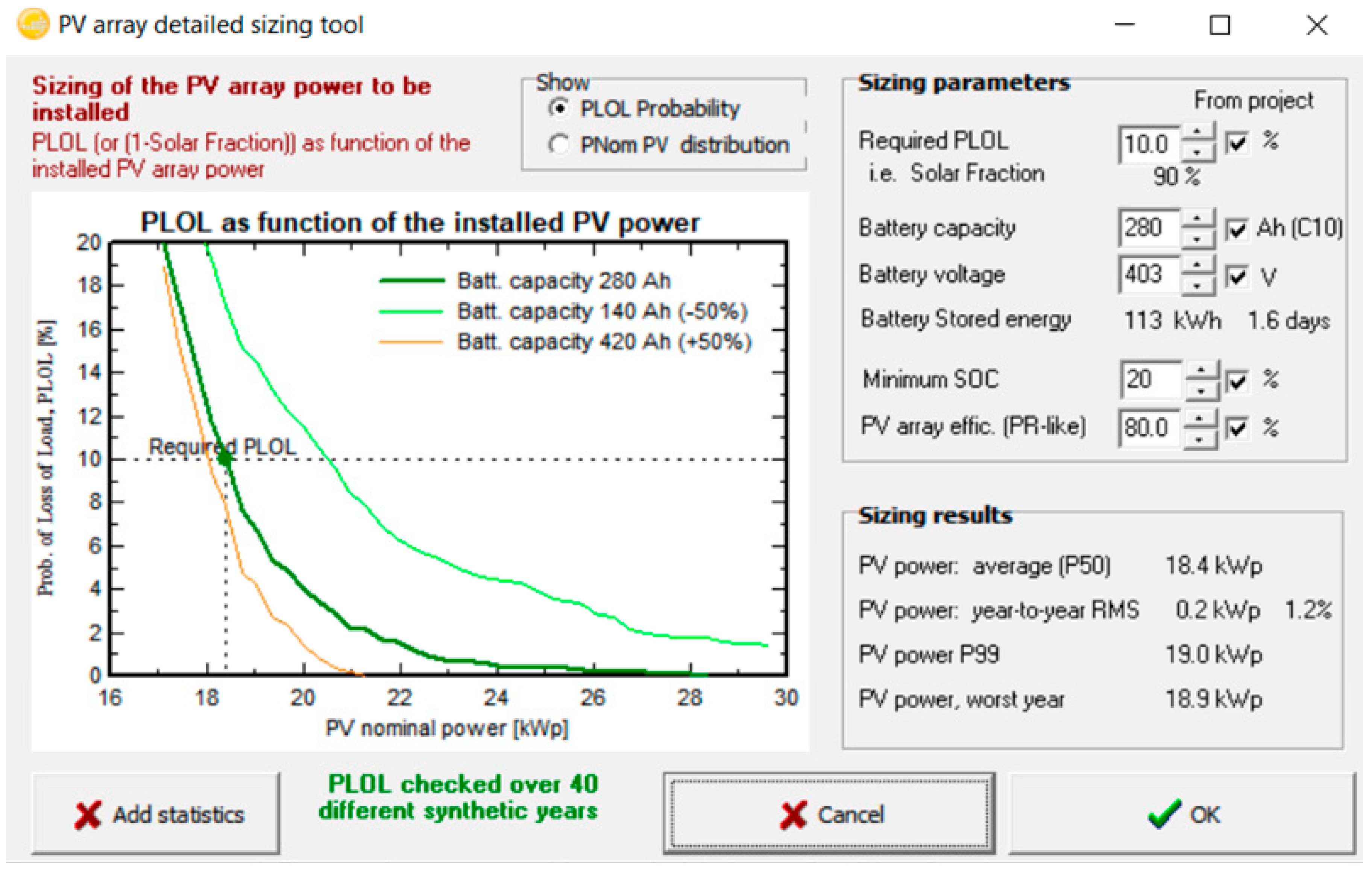
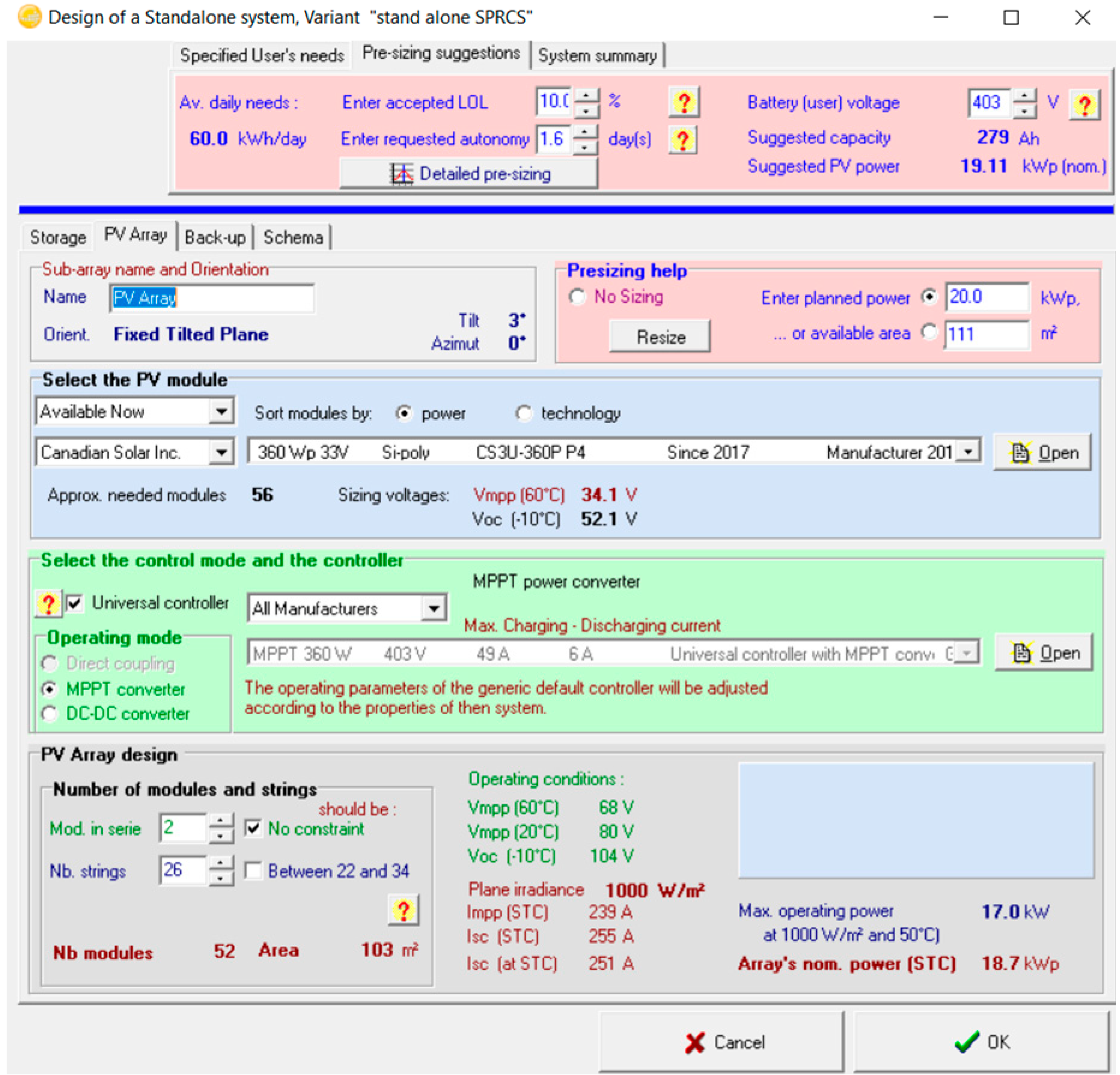
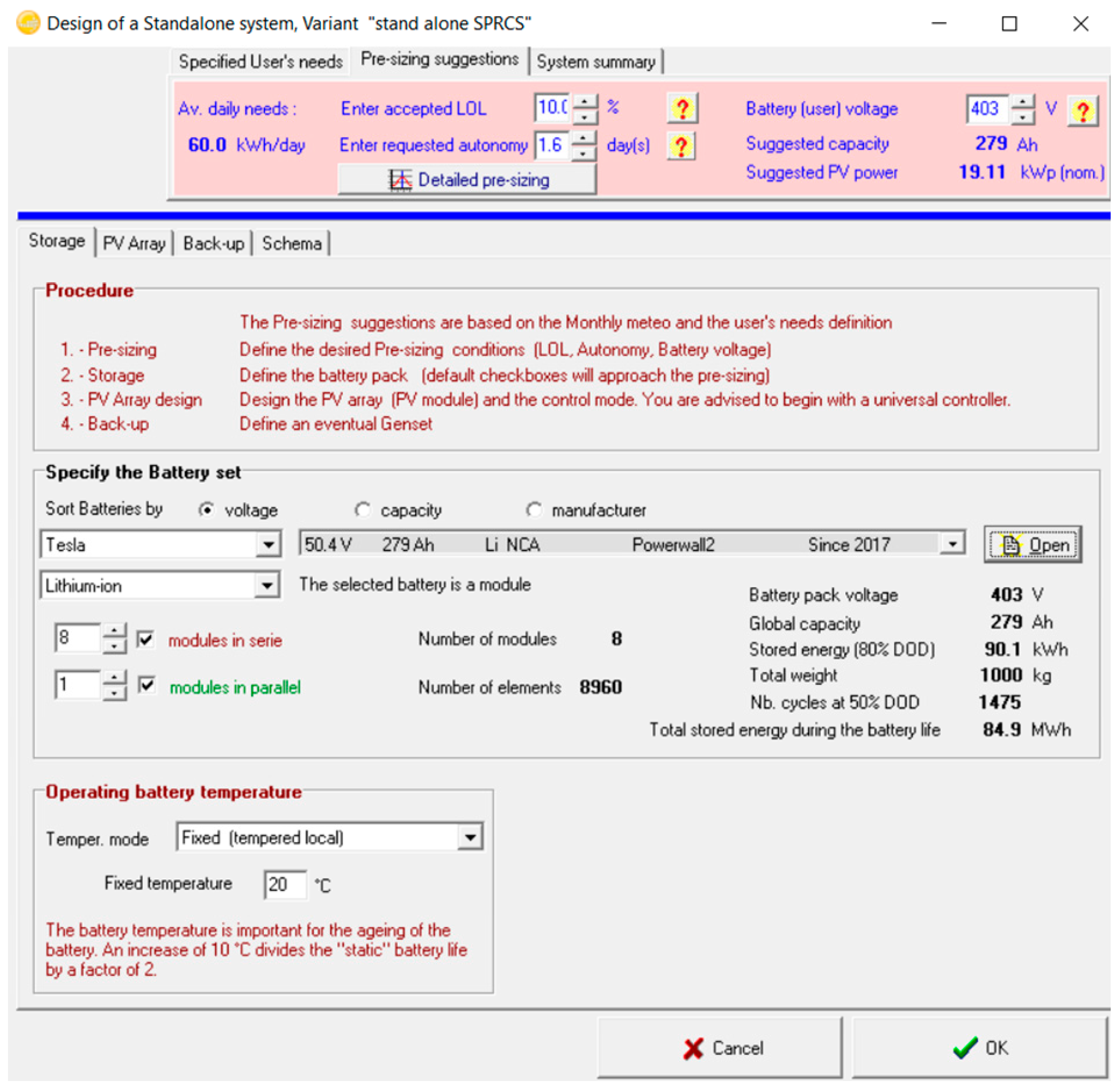
3.1. PVsyst for Sizing

For this SPRCS the entire system was modelled and analysed using PVsyst. PVsyst helps to study sizing required for a PV plant, simulating and analysing both on-grid or off-grid systems. It includes extensive loss diagram and identification of system design weakness is possible. For this particular application, like modelling SPRCS for EVs, it was assumed that the load for SPV was constant. As per the sizing of the SPRCS, the load was considered as a lithium-ion battery, and it remained constant for the entire year. Based on this assumption, the load for the SPV was available during 11.00 h to 15.00 h based on this charging period and it was observed that 20 kWp SPV could generate approximately 60–66 kWh per day. With this generation, the SPV would be able to generate 120 kWh for two days to charge the system battery of 279 Ah to 90%.
The proposed system consisted of a 3D modular structure based solar photovoltaic (SPV) system ([39] and the supplementary information of ref [39]), MPPT controllers, batteries with an appropriate battery management system (BMS), back-up generator (if needed) and regulators carrying control algorithms to charge the EVs or to provide ancillary services to the local distribution grid. The scheme of the proposed system is shown in Figure 2. The modular system architecture is consisted of any mobile structure which we could utilize to feed the load. For instance, this proposed modular structure consisted of a container, which could hold all the necessary equipment to generate onsite power and could store energy in battery banks. The modular structure consisted of tower-shaped bifacial solar panels. By adopting the tower-shaped structure, the nominal area required to install 20 kWp was reduced predominantly. Therefore 3D solar towers could be placed on the container. Whenever there was a request from the EVs to charge, the request was processed and analysed the data like SOC of the EV, the geographical location of the EV in the de-centralised control room. Based on the requirements, the plug and play vehicle could be dispatched to a particular EV to charge. This particular design for the system was used only for emergency charging for the EVs. The controller would control the battery discharge or incoming demand by the required level of SOC of the incoming vehicle. By doing so, SPRCS could provide enough charge to the incoming vehicle so that it could reach the nearest CS or workplace charging or home charging.
The system could act as a virtual mobile power plant where it could be connected to support the grid wherever the weak bus in the network. The main parameters for the design of service vehicle are in Table 1.
The modular system could be connected to a three phase inverter and then connected to suitable high-speed DC charging equipment like ASEA Brown Boveri (ABB’s) Terra 54 CT, [40] as the charging equipment could provide one DC charging session with capabilities of delivering 22 kW output power. It could even be directly connected to the EVs to facilitate to DC-DC link to provide DC fast charging. The proposed modular System would be capable of completely charging two Nissan leaf of 40 kWh capacity. Therefore the system was designed in such a way that it will charge the EVs required to reach nearest charging location. Further, upon request from the distribution system operator, the SPRCS can be connected to the weaker bus in the distribution network to support ancillary services.

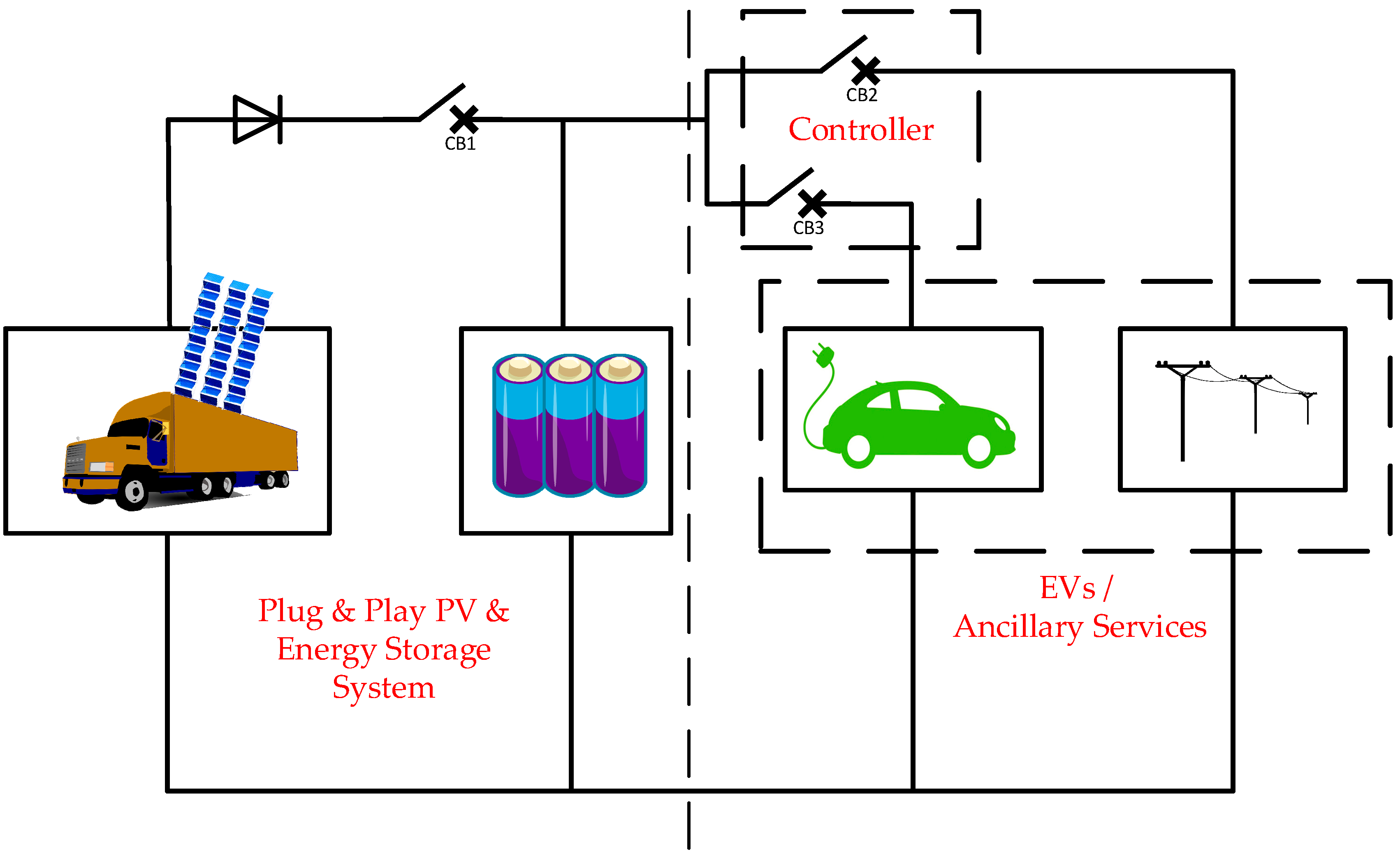
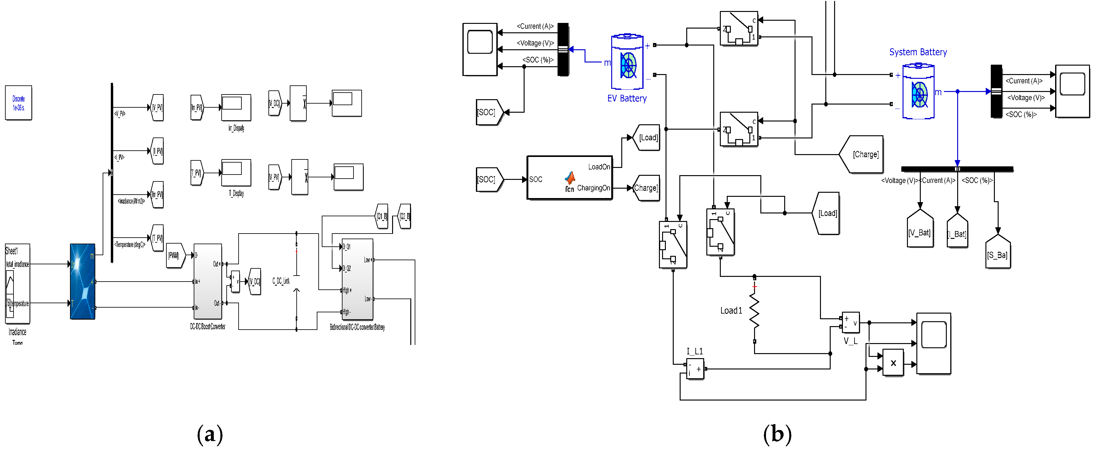
3.2. Modelling of the Proposed System

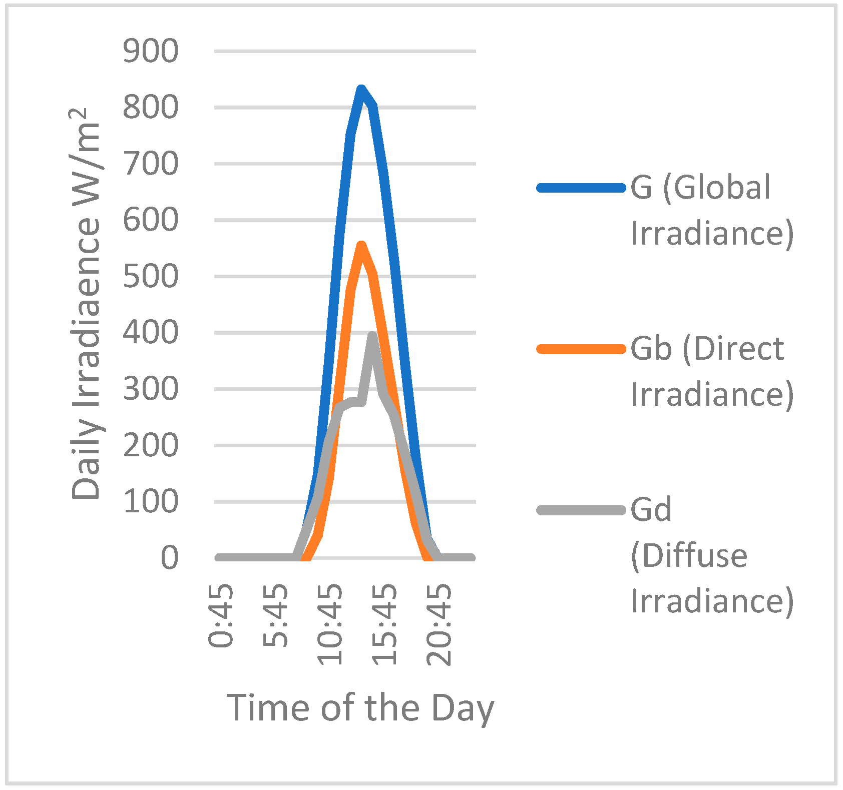
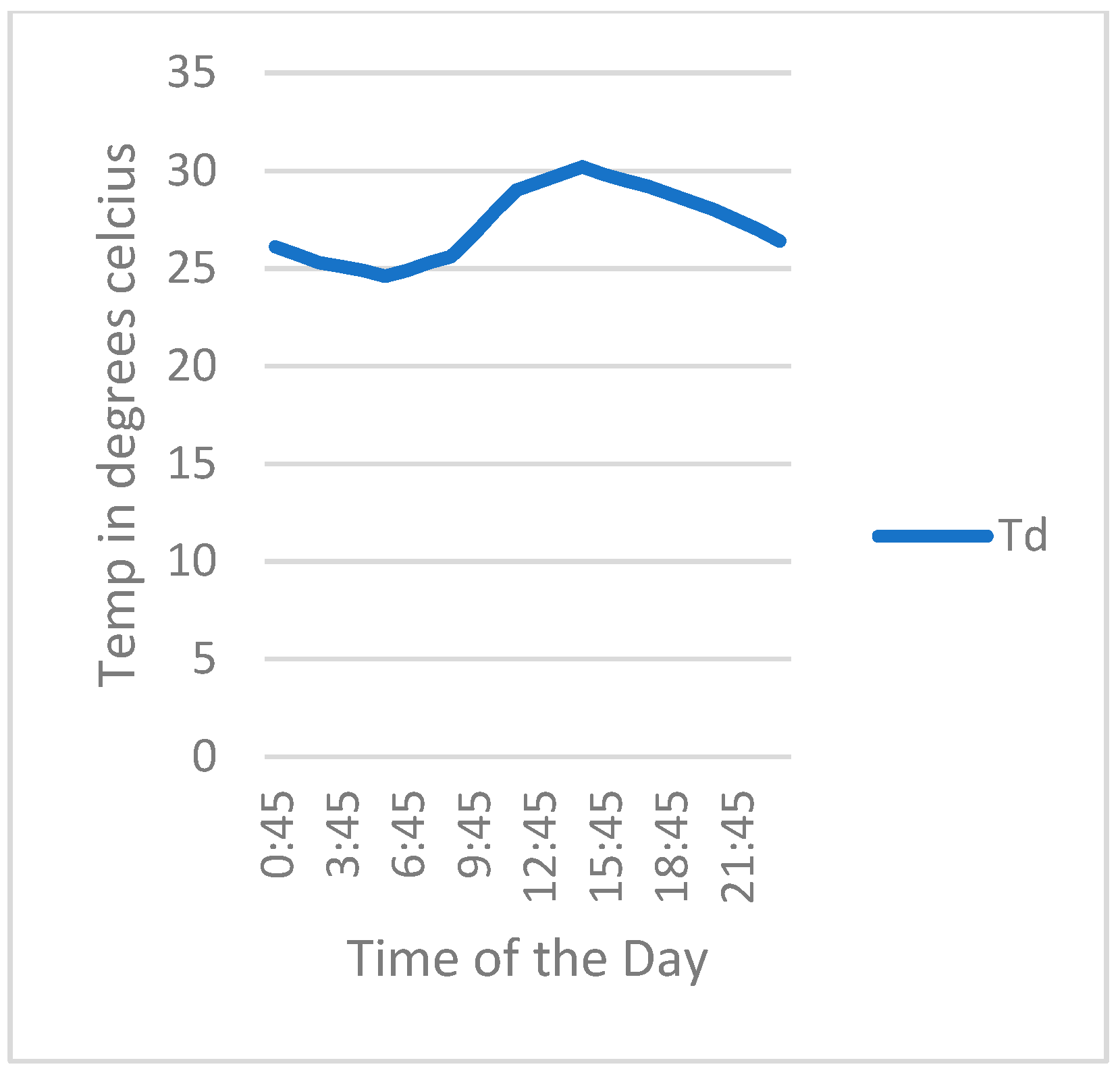
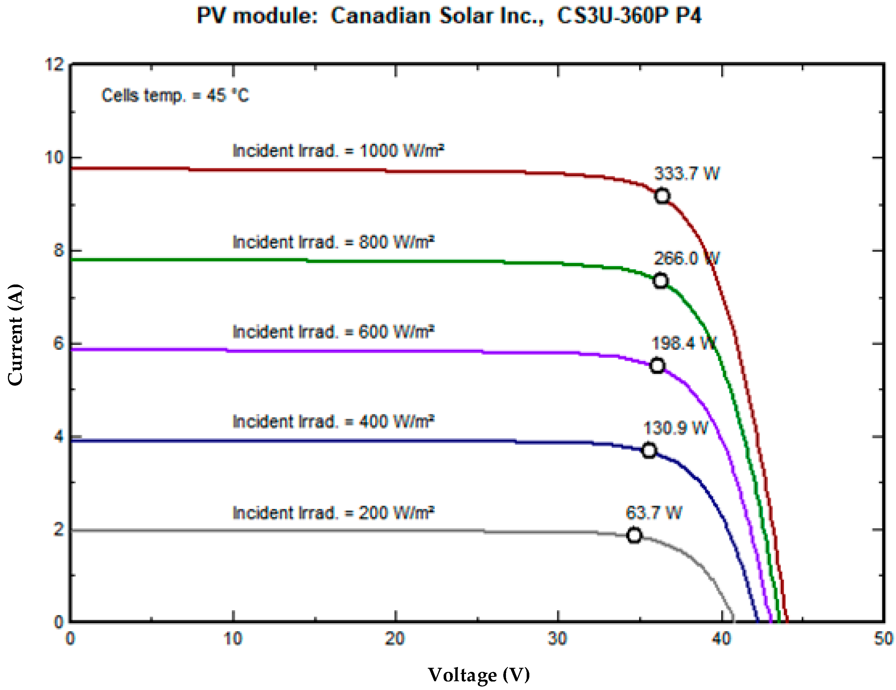
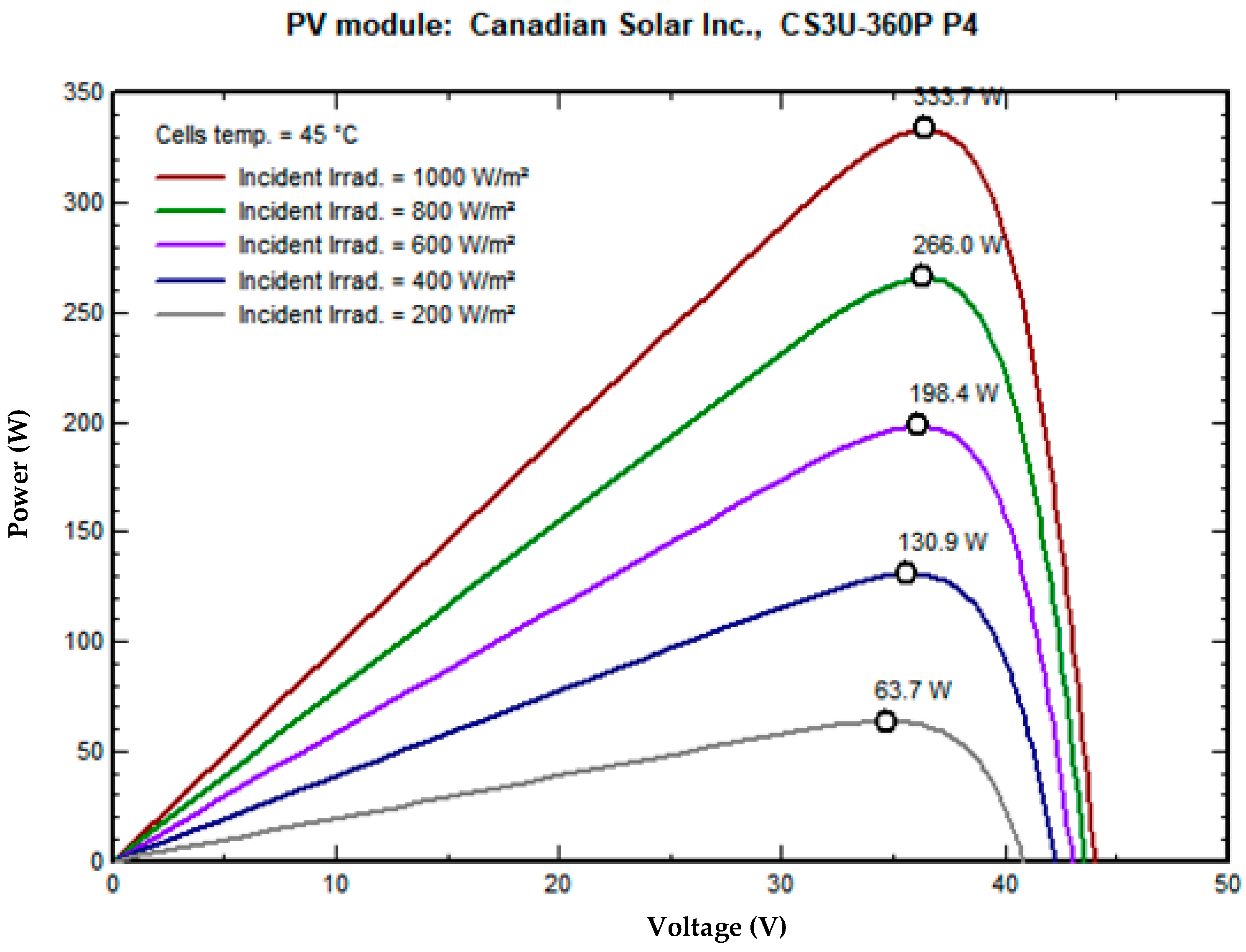
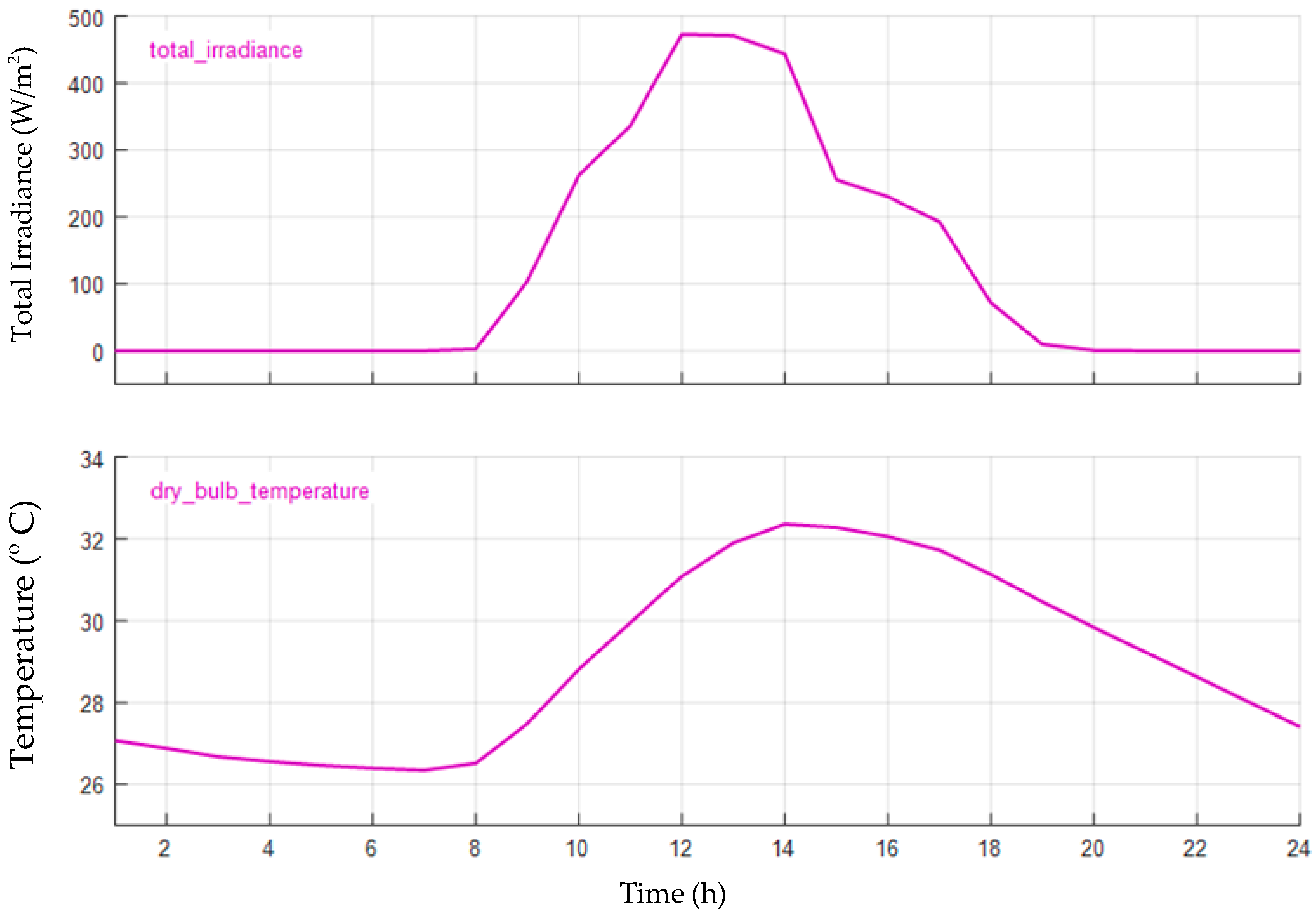
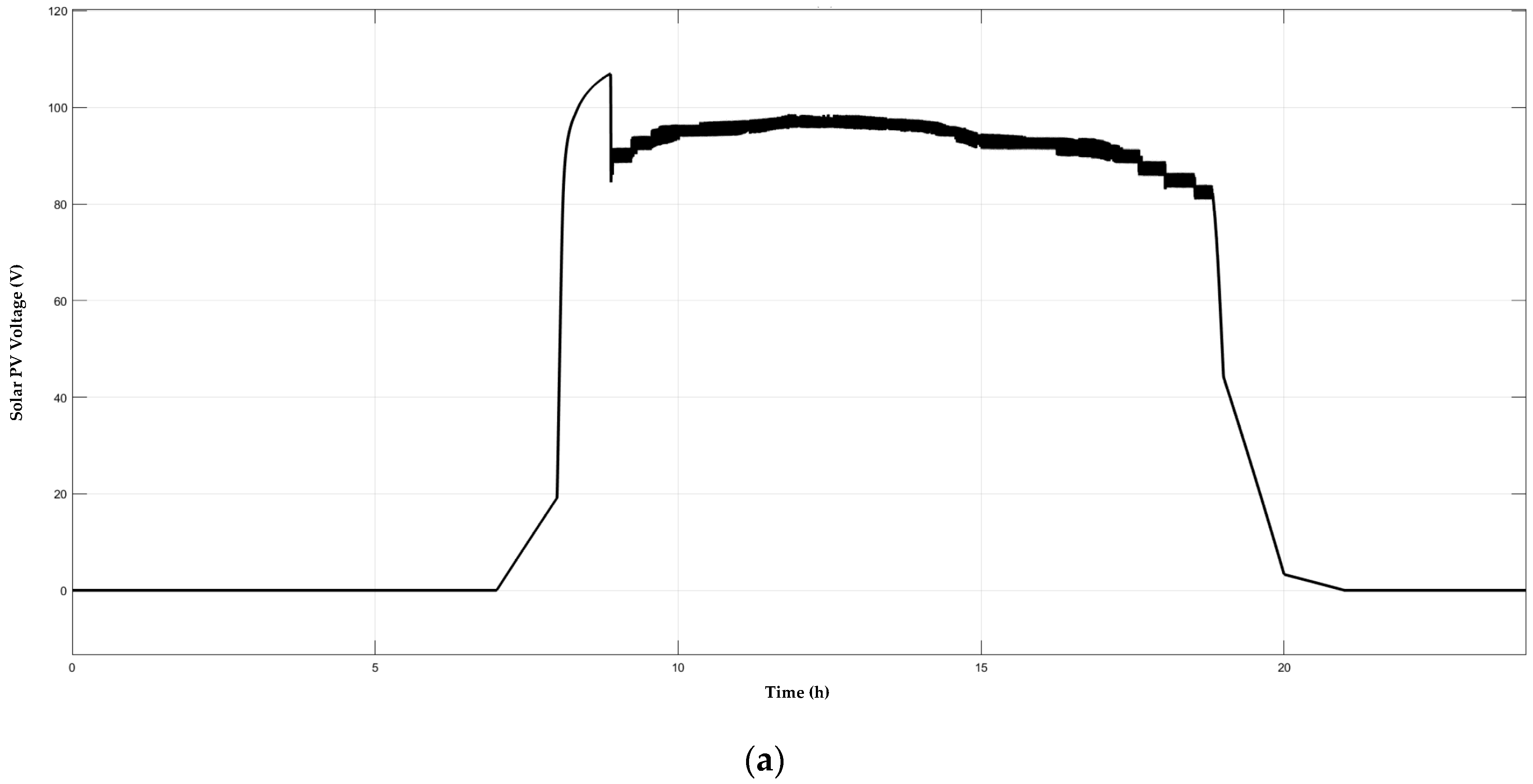
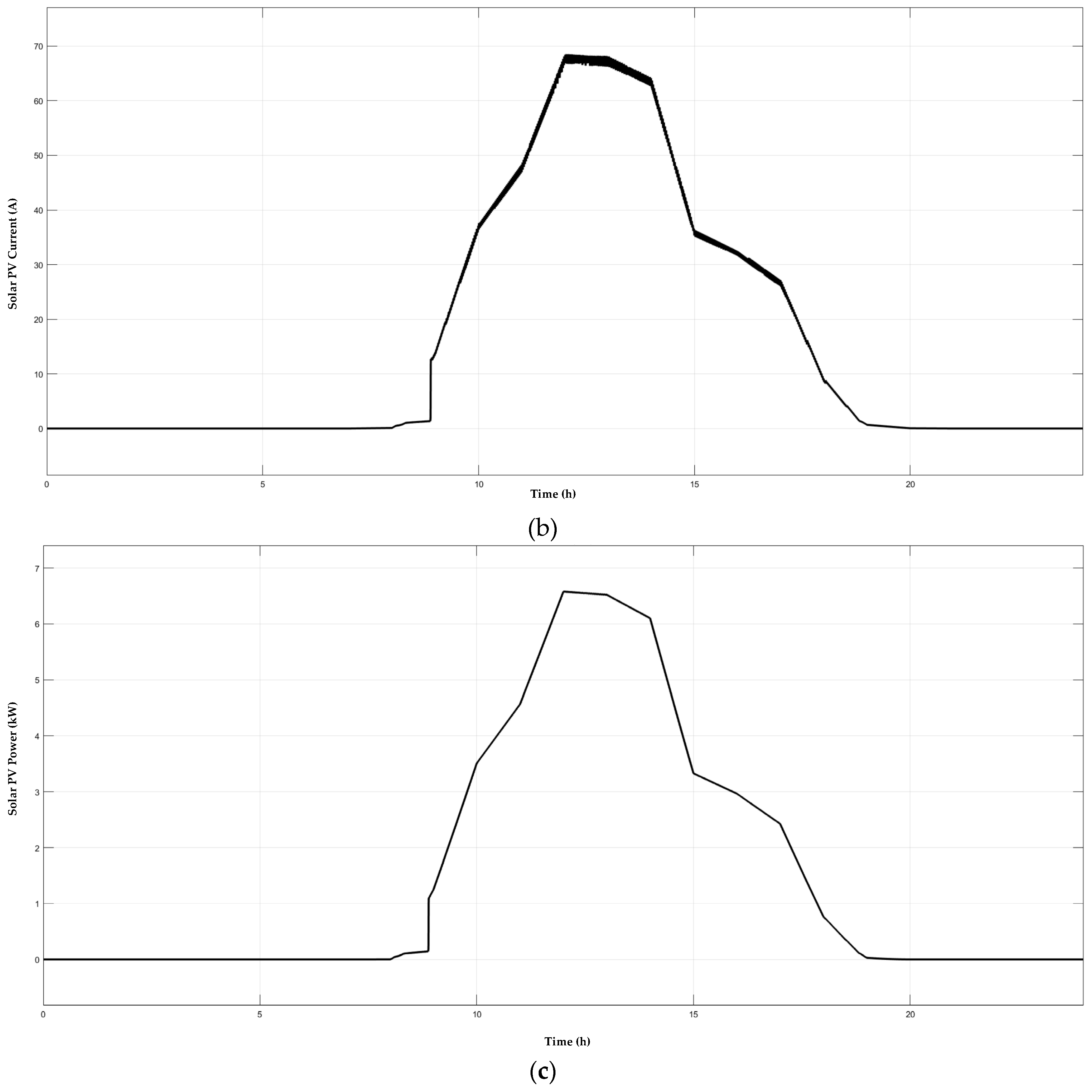
3.2.1. PV Array Output

The modelling of the solar photovoltaic system was carried out by considering the work presented in the article [25] PV array output can be determined from the Equation (1).
P p v = S I · η · A
where SI is the annual solar insolation in kWh/m2, η is the efficiency of the solar panel module and A is the surface area of the solar array. The effect of temperature can be considered by the Equation (2) where η t is the temperature de-rating effect. As we know, solar panels need to function in the appropriate temperature and if the temperature increases, efficiency decreases, which in turn reduces the power output.
η t = 1 [ β ·   ( T C T S ) ]
The SPV output depends on the temperature and de-rating effect. The governing equation for SPV output is changed to Equation (3). Where W, is the rated capacity of PV panel in kW, β is the temperature coefficient, Gc is the solar insolation in real-time condition, Gs is the solar insolation in standard test conditions, Tc and Ts are the temperatures of the PV cell at real-time and standard test conditions.
P P V = W · η t · ( G C G S ) [ 1 + β ( T C T S ) ]
The modular system was designed for the geographical location of Subang Jaya in the peninsular of Malaysia. Due to the varying climatic condition of this place, there are considerably three and a half to four hours of clear sunshine is available. As the proposed model was a 3D modular structure, the PVsyst tool was not able to simulate the proposed structure. So as per the compatibility of the tool, a normal flat roof structure was considered for simulation. In order to get maximum irradiation on the collector plane, the proposed design consisting of fixed tilt was considered despite seasonal tilt. The tilt angle was 3° Based on the latitude of this location and the yearly irradiation yield on the collector plane was maximum, which was 1600 kWh/m2. The daily irradiance profile for inclined plane at 3° is shown in Figure 3 followed by the Daily average temperature in Figure 4.
Overall, the system production for the entire year month wise is in Table 2, and overall PV conversion losses were given in Table 3 PV loss due to irradiation level, PV loss due to temperature, module array mismatch, Ohmic wiring loss, and unused energy loss were considered for PV converting efficiency. It showed that in March, there was a massive production of horizontal global irradiation (HGI) of 150.3 kWh/m2. Besides, the global effective corrected incidence angle modifier (IAM) was 145.9 kWh/m2. Available solar energy was 2265 kWh for March. The energy generated from the SPV was enough to charge the system batteries. The energy supplied to the user such as the system batteries consumed 1844 kWh of energy for the entire month of March. The probability of loss-of-load (PLOL) was assumed to be 10%, i.e., the solar fraction was 90%, as given in Figure 5. PVsyst provided pre-sizing requirements in which PLOL was checked over 40 different years and provided an approximate sizing of 20 kWp SPV.
Sizing of the SPV required to charge the system batteries is shown in Figure 6. It consisted of pre-sizing suggestions and user needs. The system requirement was to charge the system batteries during a time when abundant solar energy was available. For this work, the sizing of the SPV system was 20 kWp. The voltage vs. current (VI) and power vs. voltage (PV) characteristics curve for the PV module CS3U-360P P4 are shown in respective Figure 7 and Figure 8. On average irradiation between 500 W/m2 to 800 W/m2, the chosen solar panel was able to produce 198 to 266 W/module.

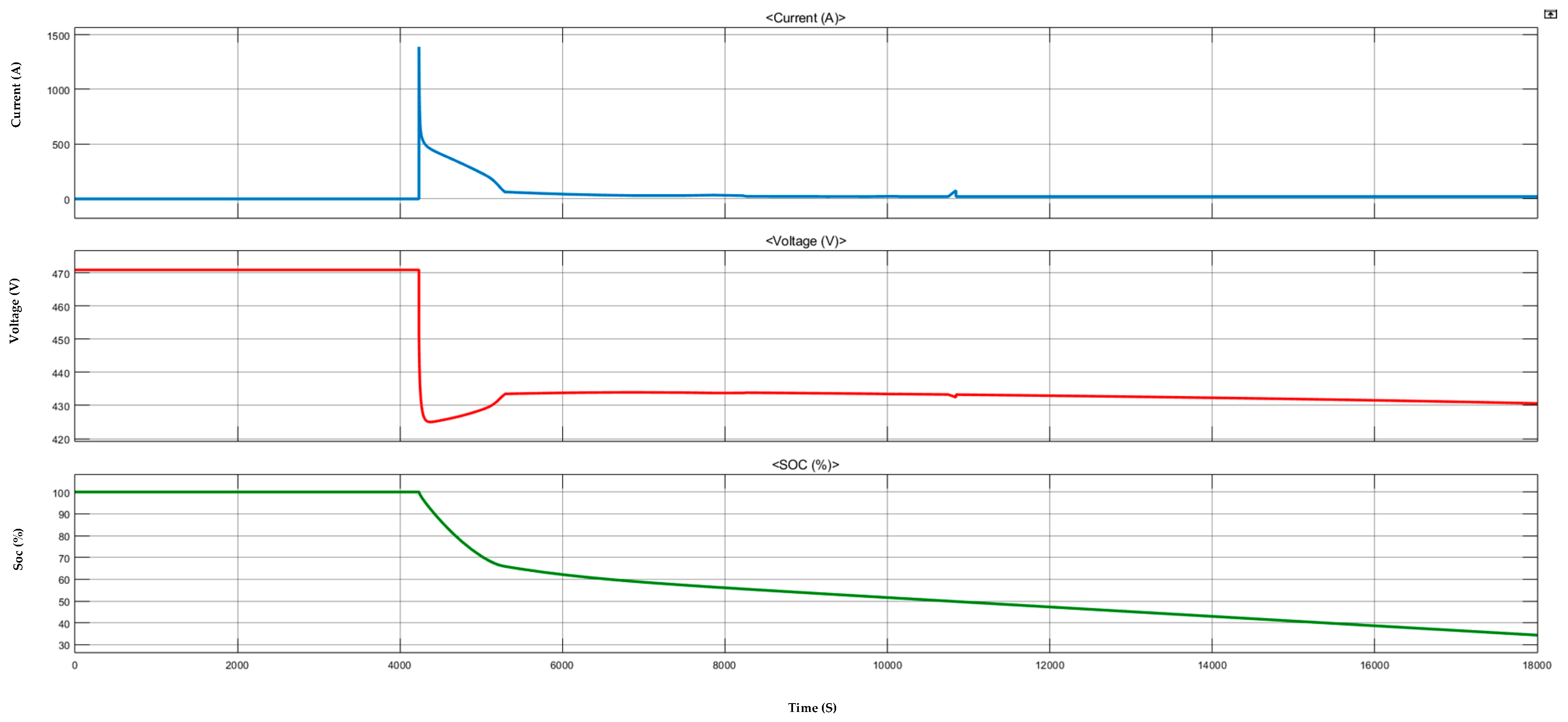
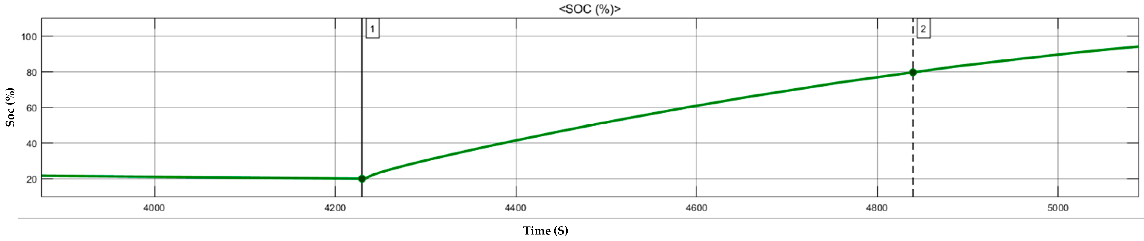
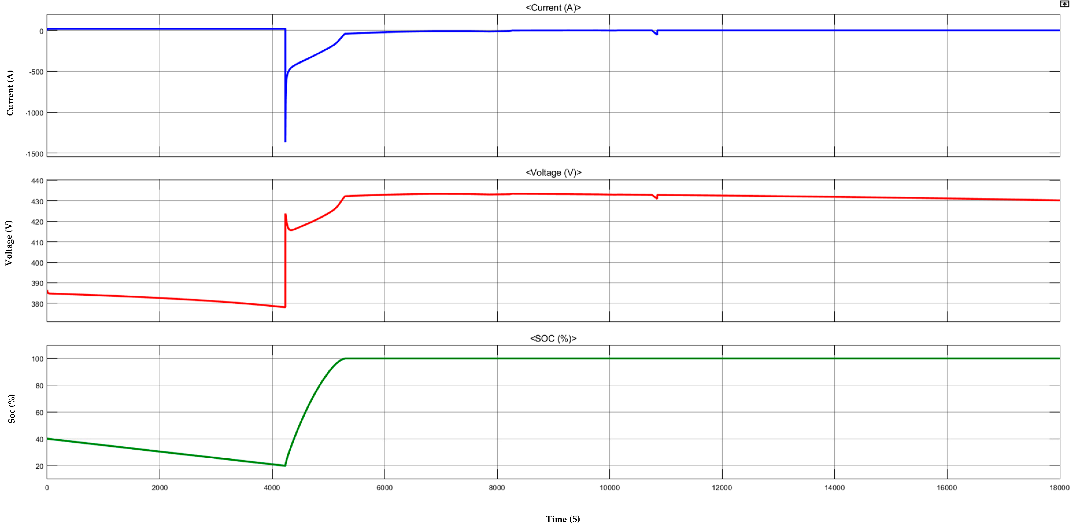
3.2.2. Battery Modelling

Modelling of the battery system was carried out by considering the work presented in the [25] In our system, a lithium-ion battery was used for storing the energy generated from the SPV. The battery capacity is 279 Ah. The system battery could be fully charged by utilising solar generation generated for two days. This battery system was going to act as an intermittent storage unit to facilitate rapid charging to EVs. In this system, the intermittent battery storage was designed to have SOC of 90%. The charge in the battery can represent by the Equation (4), and initial battery SOC can be represented by Equation (5). The SOC is considered as a random variable with respective to the distance. So the SOC with respect to distance travelled is represented by Equation (6) where Vbat, Ibat is correspond to the voltage and current needed to charge with respect to time, d and dmax are the distance travelled and maximum distance that can be travelled by an EV.
Q B a t t e r y = S O C + 0 t V b a t I b a t dt
B S O C = Q b a t Q b a t , m a x
E = 1 d d m a x ; 0 < d < d m a x
Overall, battery performance is presented in Table 4 in which for the entire year, the battery charging/discharging efficiency was maintained at above 90%. During the entire time, the system battery SOC range maintained between 20% to 90%. It was clear from the simulation that battery-discharging current on average for a day was 47.36 A. With the system voltage of 403 V the SPRCS was always able to produce approximately more than 17 kW to the electric vehicles at any time.
The charge/discharge vs. state of charge (SOC) and discharge characteristics curve for C10 are shown in Figure 9a,b. In that, the curve shows that the battery is capable of charging at 56 A for 5 h, 14 A for 20 h. Similarly, the battery could discharge at 55.8 A for 5 h. The discharge profile of the system was designed for C10. System batteries would discharge at 403 V at a nominal capacity of C10. From the curve, it was visible that for charging, cut-off voltage was 58.8 V and discharging, cut-off voltage was 35.0 V. Battery modelling was carried out in PVsyst, as shown in Figure 10. The chosen batteries were 50.4 V 279 Ah lithium-ion.

3.2.3. Electric Vehicle Demand

Power consumed by EV is with respect to the distance travelled, battery capacity and mode of driving [25]. Therefore, the general power requirement can be analysed by the following equations:
P D =   K d . E k T
P D = Q b a t × ( S O C m a x S O C ) T
P =   i = 1 N P D
From Equation (7), Kd is kilometer driven, Ek is energy required per kilometer, and T is the time required to charge the vehicle. The above equation held good in our system as the central battery storage unit needed to charge from the SPV. The power demand could be represented by Equation (8) where Qbat is battery capacity, SOCmax is the upper limit of battery SOC, and T is the time required to reach SOCmax. Total power required for N number of vehicles can be calculated from Equation (9).

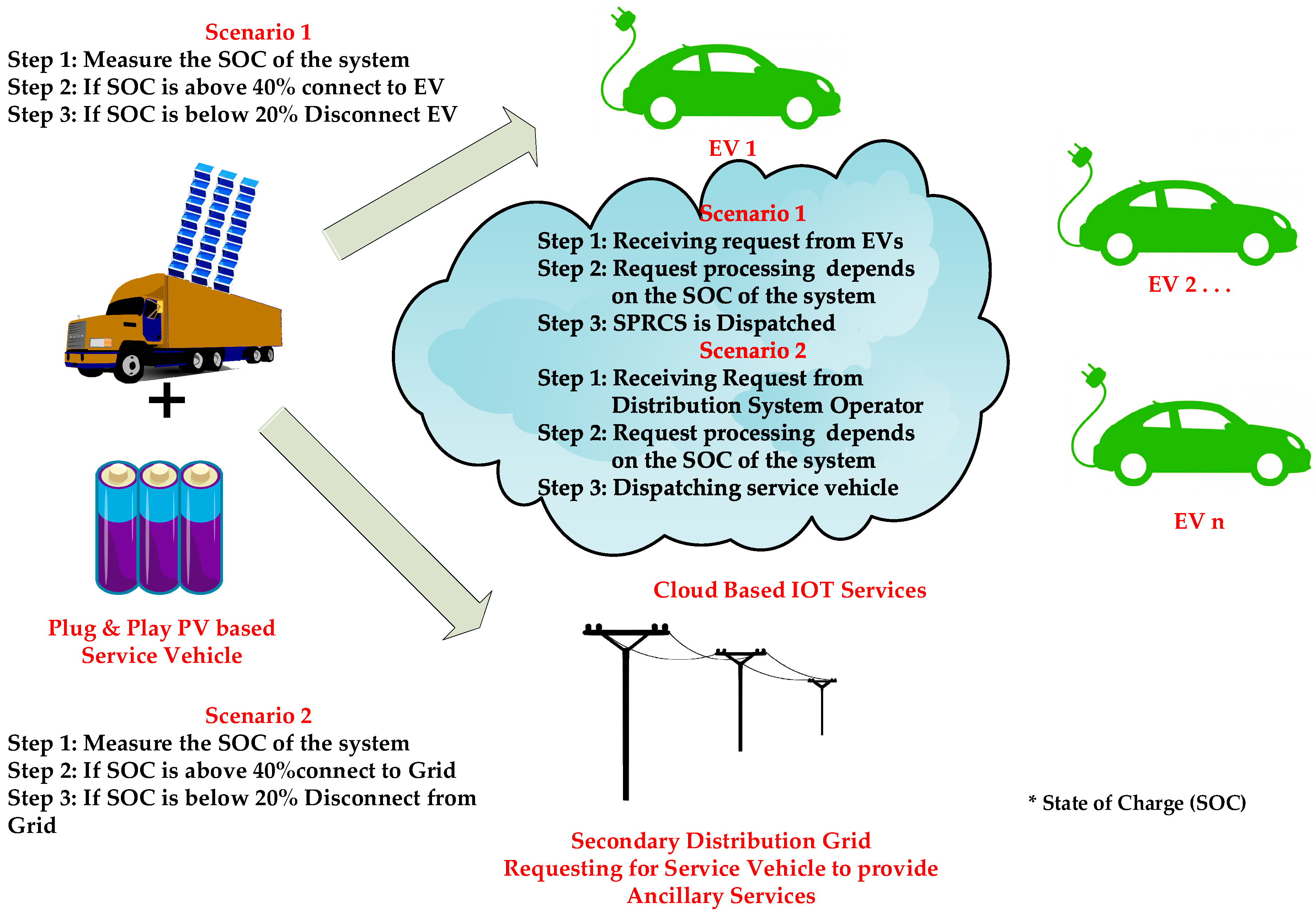
3.3. Proposed Algorithm

In order to control the system battery to charge a limited amount of energy in the EV, a robust algorithm is needed where it can be variable depending on the sequences and dynamic constraints. The following algorithm is shown in Figure 11 and it acts as a basis for simple control for discharging of the system battery.
Based on the above algorithm, the system batteries got charged when there was abundant solar generation. The system would measure its SOC whenever there was charging or discharging sessions. Incoming request from EVs to get charged was monitored by the controller. The controller would compare the SOCs of both EV and the system, and then the system would initiate a charging session. Once the charging session was initiated, the controller would keep measuring the updated SOCs, and as per the algorithm, the controller may engage or disengage the charging session. The above constraints were simulated in MATLAB, and the proposed SPRCS could utilized for emergency charging.

4. Results and Discussion

The proposed system consists of a solar panel block where irradiance and the daily average temperature was given as input. The power generated from the SPV was then connected to the maximum power point technique MPPT controller maintaining constant DC voltage. As per the schematic, the system batteries were connected directly to the MPPT controller. In this design, the perturb and observe method was used for MPPT. The essential operation of maximum power was monitored continuously and fed as feedback to the controller. By either increasing or decreasing the operating voltage, it was possible to maintain maximum power in the system. The maximum power output from the MPPT was directly connected to the boost converter to boost up the voltage to the desired level. From the DC link, the batteries were connected. Based on the provided algorithm, the charging and discharging of batteries took place.
In this paper, SPRCS was intended for emergency charging. Therefore, the algorithm dealt with collecting SOC from the incoming EV. Then based on the available SOC in system batteries and the provided technical constraints, the controller would allow the power flow between system batteries and EV battery. In order to provide rapid charging, the algorithm was programmed in such a way that SPRCS would charge the EV required level of the available SOC requested by the user. With an additional amount of charging, the EVs would able to reach a nearby charging station or workplace charging or home charging.
The first part of the simulation showed and explained about the standalone solar charging system to charge the proposed system. The proposed system consisted of batteries with the capacity of 279 Ah and 403 V. The solar system is fed with real-time irradiance and temperature data for the chosen location Subang Jaya, Malaysia. The array power was maintained at maximum by using an MPPT controller. From the controller, it was fed to boost converter to charge the system batteries (on-board batteries). The second part of the simulation showed the discharging of the on-board batteries to charge incoming EVs. The plug and play SPRCS was simulated using MATLAB/Simulink software shown in Figure 12a,b. The system consisted of standalone 20 kWp SPV that was connected to the MPPT controller. The MPPT controller was driven by the perturb and observation method. Incoming EVs battery was simulated as an incoming battery, which was directly coupled to the system batteries as direct coupling lead to fewer losses when compared with another available system. However, the main drawback of the system was that once the considered amount of charge was fed to EV battery the system battery would tend to lose its charge, which in turn will reduce the voltage. Therefore as of now, the present system after particular charging sessions, the system batteries cannot function in fast charging mode. The real-time input for the chosen location as a signal to the solar panel module in Simulink is shown in Figure 13.
The voltage, current, and power produced from the SPV in which from the curve, it was understood that system batteries were charged during the entire generation are shown in Figure 14a–c.
The battery discharging to feed the load, such as EV battery, is shown in Figure 15, Figure 16 and Figure 17. From the analysis of the SPRCS, Nissan LEAF ASCENTA [41] 40 kWh can give up to 168 miles. Which in turn states that rapid charging gives Nissan LEAF ASCENTA a 100-mile charge in 10.25 min. The above system output is provided without considering losses. Based on the design and from the charging curves, it is evident that charging from 20% to 80% would take approximately 10.25 min. Once we implement a real-time system there might be 5% to 10% more time to charge by considering the real-time system losses, battery temperature, and DOD of system battery the designed SPRCS could equally provide rapid charging as stated by CHArge de Move (CHAdeMO) [42].

5. Economics and Carbon Balance

The proposed SPRCS consisted of a modular 3D structure for bifacial solar modules, system batteries, charge controllers, and three-phase inverters along with cooling unit that could be equipped in the 20-foot container trailer. On a rough investment to design and construct SPRCS that could consist of the following components and its approximate prices in MYR is given in Table 5. As this was proposed as a concept of future SPRCS, the rates incurred for the support, settings, wiring, and other miscellaneous were not considered.
By considering government taxes, annuities and running costs, we can be in the position to say the cost of the energy produced would be 1.04 Myr. Based on the SPRCS produced emissions would be 36.54 t CO2. The produced emission was a summation of emissions produced by modules of 34,254 Kg CO2 and support structure including batteries, and container trailer was 2289 Kg CO2. It can be noted that the emissions from solar modules have a significant contribution of around 93.7% of the total emissions. From the SPV the replaced emissions were 397.1 t CO2. On an average system lifetime of 25 years and considering annual degradation of 1% the CO2 emission balance could be of 316.4 t CO2. As per the reference [43], the avoided Emissions calculator, 232.4 GWh of solar photovoltaic energy avoided 0.1541 million tonnes of CO2 in 2016 with the energy mix of 42.2% coal, 53.6% natural gas and 4.2% of oil. Therefore, an EV charging station powered by solar photovoltaic energy would be more advantageous than any other energy mix.

6. Summary

From the above analysis, it was shown that the mobile plug and play SPRCS was designed with a 20 kWp standalone solar power plant with a system battery capacity of 279 Ah along with direct control to transfer the power from system batteries to the incoming EVs. The 3D modular structure was utilized for erecting panels on the container trailer in a futuristic approach. However, in order to get a maximum yield on the collector plane for the location of Subang Jaya, Malaysia, the fixed tilt angle was considered as 3°. The entire system was designed using PVsyst software and analysis was carried out in MATLAB/Simulink. Standalone SPRCS is designed and analysed in MATLAB/SIMULINK to calculate the time taking to charge the incoming EV battery from the system battery. It was found that time taken to charge the EV battery from 20% to 80% was 10.25 min.

7. Conclusions

It is evident that due to the rise in EVs in future, the rise in demand for rapid charging station will increase. Due to this situation, there will be tremendous stress on the distribution grid. All EV owners would like to charge their vehicle like fuel in a gas station. So various research works are working on to increase the life cycle of batteries, increasing the power density of batteries, and designing of more intense rapid stations. However, during emergencies as well as the gathering where there is limited EV parking or no parking slots for charging, the proposed SPRCS can be a viable solution.
With further designing of intelligent controllers and utilization of high-efficiency solar modules, there are many possibilities to reduce the size of the system as well as the cost incurred to construct the system. The above-proposed system can also act as an ancillary service provider in which it will be further analysed in upcoming research work. The above system is limited to the availability of charge in the system batteries, so when the battery voltage level decreases, the SPRCS may act as a level two charging facility.

Author Contributions

Conceptualization, C.A.V., R.A. and K.S.P.O.; writing the manuscript, K.S.P.O. and G.R.; review and editing of the manuscript, C.A.V. and R.A.

Funding

This research was funded by Taylor’s University through its TAYLOR’S PhD SCHOLARSHIP Programme through grant TUFR/2017/001/01. Meanwhile the APC was funded by UNITEN BOLD publication fund.

Acknowledgments

This work was supported by Taylor’s University through its TAYLOR’S PhD SCHOLARSHIP Programme through grant TUFR/2017/001/01.

Conflicts of Interest

The authors declare no conflict of interest.

References

  1. International Renewable Energy Agency. Electric Vehicles-Technology Brief; International Renewable Energy Agency: Abu Dhabi, UAE, 2017; ISBN 9789295111004.
  2. EV Charging Made Easy. Available online: https://chargev.my/ (accessed on 2 July 2019).
  3. International Energy Agency. Global EV Outlook 2018; International Energy Agency: Paris, France, 2018.
  4. IEA. Global EV Outlook 2019 to Electric Mobility; IEA: Paris, France, 2019.
  5. Gartner, J. Mobile EV Chargers Deliver Power Where It’s Needed. Available online: https://chargedevs.com/features/mobile-ev-chargers-deliver-power-where-its-needed/ (accessed on 5 August 2019).
  6. EV Safe Charge. EV Charge Mobile for All Your Event Charging Needs. Available online: https://evsafecharge.com/mobile-ev-charging-stations/ (accessed on 5 August 2019).
  7. Hawkins, A.J. Volkswagen’s Mobile Charging Station Will Help Solve a Key Problem with EVs. Available online: https://www.theverge.com/2019/1/2/18165265/volkswagen-ev-mobile-charging-station-battery (accessed on 5 August 2019).
  8. Dai, Q.; Liu, J.; Wei, Q. Optimal photovoltaic/battery energy storage/electric vehicle charging station design based onmulti-agent particle swarm optimization algorithm. Sustainability 2019, 11, 1973. [Google Scholar] [CrossRef]
  9. Kadar, P.; Varga, A. PhotoVoltaic EV charge station. In Proceedings of the IEEE 11th International Symposium on Applied Machine Intelligence and Informatics (SAMI 2013), Herl’any, Slovakia, 31 January–2 February 2013; pp. 57–60. [Google Scholar]
  10. Chen, Q.; Liu, N.; Wang, C.; Zhang, J. Optimal power utilizing strategy for PV-based EV charging stations considering Real-time price. In Proceedings of the 2014 IEEE Conference and Expo Transportation Electrification Asia-Pacific (ITEC Asia-Pacific), Beijing, China, 31 August–3 September 2014; pp. 1–6. [Google Scholar]
  11. Liu, J.; Tang, H.; Ping, Z.; Zhou, L. Optimal charging control for electric vehicles in stand-alone PV charging stations. In Proceedings of the 11th World Congress on Intelligent Control and Automation, Shenyang, China, 29 June–4 July 2014; pp. 1749–1754. [Google Scholar]
  12. Islam, M.S.; Mithulananthan, N.; Bhumkittipich, K. Feasibility of PV and battery energy storage based EV charging in different charging stations. In Proceedings of the 2016 13th International Conference on Electrical Engineering/Electronics, Computer, Telecommunications and Information Technology (ECTI-CON), Chiang Mai, Thailand, 28 June–1 July 2016; pp. 1–6. [Google Scholar]
  13. Demeter, L.N.; Turcin, V.; Hanek, M.; Vataselu, G.; Zorlescu, B. Modular solution for charging the batteries of electric bikes parked on public domain. In Proceedings of the 2017 Electric Vehicles International Conference (EV), Bucharest, Romania, 5–6 October 2017; pp. 1–5. [Google Scholar]
  14. Mouli, G.R.C.; Kefayati, M.; Baldick, R.; Bauer, P. Integrated PV charging of EV fleet based on energy prices, V2G, and offer of reserves. IEEE Trans. Smart Grid 2019, 10, 1313–1325. [Google Scholar] [CrossRef]
  15. Zhang, Y.; He, Y.; Wang, X.; Wang, Y.; Fang, C.; Xue, H.; Fang, C. Modeling of fast charging station equipped with energy storage. Glob. Energy Interconnect. 2018, 1, 145–152. [Google Scholar]
  16. Aluisio, B.; Dicorato, M.; Ferrini, I.; Forte, G.; Sbrizzai, R.; Trovato, M. Optimal Sizing Procedure for Electric Vehicle Supply Infrastructure Based on DC Microgrid with Station Commitment. Energies 2019, 12, 1901. [Google Scholar] [CrossRef]
  17. Yousif, F.; Alghoul, M.A.; Alfegi, E.; Asim, N. Simulation of Hybrid PV-“3 Phase Grid” Electric Vehicle Charging System. In Latest Trends in Renewable Energy and Environmental Informatics; kuala lumpur, Malaysia; WSEAS Press: Cambridge, UK, 2013; pp. 304–309. [Google Scholar]
  18. Fathabadi, H. Utilizing solar and wind energy in plug-in hybrid electric vehicles. Energy Convers. Manag. 2018, 156, 317–328. [Google Scholar] [CrossRef]
  19. Eldeeb, H.H.; Faddel, S.; Mohammed, O.A. Multi-Objective Optimization Technique for the Operation of Grid tied PV Powered EV Charging Station. Electr. Power Syst. Res. 2018, 164, 201–211. [Google Scholar] [CrossRef]
  20. Esfandyari, A.; Norton, B.; Conlon, M.; McCormack, S.J. Performance of a campus photovoltaic electric vehicle charging station in a temperate climate. Sol. Energy 2019, 177, 762–771. [Google Scholar] [CrossRef]
  21. Islam, M.S.; Mithulananthan, N. PV based EV charging at universities using supplied historical PV output ramp. Renew. Energy 2018, 118, 306–327. [Google Scholar] [CrossRef]
  22. Bhatti, A.R.; Salam, Z. A rule-based energy management scheme for uninterrupted electric vehicles charging at constant price using photovoltaic-grid system. Renew. Energy 2018, 125, 384–400. [Google Scholar] [CrossRef]
  23. Novoa, L.; Brouwer, J. Dynamics of an integrated solar photovoltaic and battery storage nanogrid for electric vehicle charging. J. Power Sources 2018, 399, 166–178. [Google Scholar] [CrossRef]
  24. Grande, L.S.A.; Yahyaoui, I.; Gómez, S.A. Energetic, economic and environmental viability of off-grid PV-BESS for charging electric vehicles: Case study of Spain. Sustain. Cities Soc. 2018, 37, 519–529. [Google Scholar] [CrossRef]
  25. Karmaker, A.K.; Ahmed, M.R.; Hossain, M.A.; Sikder, M.M. Feasibility assessment & design of hybrid renewable energy based electric vehicle charging station in Bangladesh. Sustain. Cities Soc. 2018, 39, 189–202. [Google Scholar]
  26. Calise, F.; Cappiello, F.L.; Cartenì, A.; D’accadia, M.D.; Vicidomini, M. A novel paradigm for a sustainable mobility based on electric vehicles, photovoltaic panels and electric energy storage systems: Case studies for Naples and Salerno (Italy). Renew. Sustain. Energy Rev. 2019, 111, 97–114. [Google Scholar] [CrossRef]
  27. Badea, G.; Felseghi, R.A.; Varlam, M.; Filote, C.; Culcer, M.; Iliescu, M.; Raboaca, M.S. Design and simulation of romanian solar energy charging station for electric vehicles. Energies 2019, 12, 74. [Google Scholar] [CrossRef]
  28. Klingler, A.L. The effect of electric vehicles and heat pumps on the market potential of PV + battery systems. Energy 2018, 161, 1064–1073. [Google Scholar] [CrossRef]
  29. Marczinkowski, H.M.; Østergaard, P.A. Residential versus communal combination of photovoltaic and battery in smart energy systems. Energy 2018, 152, 466–475. [Google Scholar] [CrossRef] [Green Version]
  30. Savio, D.A.; Juliet, V.A.; Chokkalingam, B.; Padmanaban, S.; Holm-Nielsen, J.B.; Blaabjerg, F. Photovoltaic Integrated Hybrid Microgrid Structured Electric Vehicle Charging Station and Its Energy Management Approach. Energies 2019, 12, 168. [Google Scholar] [CrossRef]
  31. Miceli, R.; Viola, F. Designing a sustainable university recharge area for electric vehicles: Technical and economic analysis. Energies 2017, 10, 1604. [Google Scholar] [CrossRef]
  32. Ul-Haq, A.; Cecati, C.; Al-Ammar, E.A. Modeling of a photovoltaic-powered electric vehicle charging station with vehicle-to-grid implementation. Energies 2017, 10, 4. [Google Scholar] [CrossRef]
  33. Bellocchi, S.; Manno, M.; Noussan, M.; Vellini, M. Impact of Grid-Scale Electricity Storage and Electric Vehicles on Renewable Energy Penetration: A Case Study for Italy. Energies 2019, 12, 1303. [Google Scholar] [CrossRef]
  34. Domínguez-Navarro, J.A.; Dufo-López, R.; Yusta-Loyo, J.M.; Artal-Sevil, J.S.; Bernal-Agustín, J.L. Design of an electric vehicle fast-charging station with integration of renewable energy and storage systems. Int. J. Electr. Power Energy Syst. 2019, 105, 46–58. [Google Scholar] [CrossRef]
  35. Ma, W.; Wang, W.; Wu, X.; Hu, R.; Tang, F.; Zhang, W. Control strategy of a hybrid energy storage system to smooth photovoltaic power fluctuations considering photovoltaic output power curtailment. Sustainability 2019, 11, 1324. [Google Scholar] [CrossRef]
  36. Pasetti, M.; Rinaldi, S.; Flammini, A.; Longo, M.; Foiadelli, F. Assessment of Electric Vehicle Charging Costs in Presence of Distributed Photovoltaic Generation and Variable Electricity Tariffs. Energies 2019, 12, 499. [Google Scholar] [CrossRef]
  37. Sun, Y.; Zhai, S.; Cui, H.; Nan, D.; Wang, K. Frequency regulation strategy for private EVs participating in integrated power system of REs considering adaptive Markov transition probability. Electr. Power Syst. Res. 2019, 173, 291–301. [Google Scholar] [CrossRef]
  38. Han, X.; Liang, Y.; Ai, Y.; Li, J. Economic evaluation of a PV combined energy storage charging station based on cost estimation of second-use batteries. Energy 2018, 165, 326–339. [Google Scholar] [CrossRef]
  39. Bernardi, M.; Ferralis, N.; Wan, J.H.; Villalon, R.; Grossman, J.C. Solar energy generation in three dimensions. Energy Environ. Sci. 2012, 5, 6880–6884. [Google Scholar] [CrossRef] [Green Version]
  40. ABB EV Charging Infrastructure. Electric Vehicle Charging Infrastructure Terra 51 Charge Station; ABB B. V.: Rijswijk, The Netherlands, 2011; pp. 1–2. [Google Scholar]
  41. NISSAN. Range & Charging. Available online: https://www.nissan.co.uk/vehicles/new-vehicles/leaf/charging-range.html (accessed on 8 July 2019).
  42. CHAdeMO Protocol. Available online: https://www.chademo.com/ (accessed on 11 July 2019).
  43. IRENA. Avoided Emissions Calculator. Available online: https://www.irena.org/climatechange/Avoided-Emissions-Calculator (accessed on 6 August 2019).
Figure 1. Proposed plug and play solar photovoltaic rapid charging station.
Energies 12 03579 g001
Figure 2. Scheme of the proposed system.
Energies 12 03579 g002
Figure 3. Daily average irradiance.
Energies 12 03579 g003
Figure 4. Daily average temperature.
Energies 12 03579 g004
Figure 5. Probability of loss-of-load (PLOL) sizing tool.
Energies 12 03579 g005
Figure 6. Sizing of standalone PV system for solar photovoltaic rapid charging system (SPRCS).
Energies 12 03579 g006
Figure 7. VI characteristics curve for Canadian solar panel CS3U-360P P4.
Energies 12 03579 g007
Figure 8. PV characteristics curve for Canadian solar panel CS3U-360P P4.
Energies 12 03579 g008
Figure 9. (a) Characteristics curve between charge/discharge vs. state of charge (SOC); (b) discharge characteristics curve.
Energies 12 03579 g009
Figure 10. Designing of on-board storage system for SPRCS.
Energies 12 03579 g010
Figure 11. Proposed algorithm for SPRCS.
Energies 12 03579 g011
Figure 12. (a) Simulation model of plug and play SPRCS (PV system alone); (b) simulation model of plug and play SPRCS (battery section).
Energies 12 03579 g012
Figure 13. Input data to the solar panel.
Energies 12 03579 g013
Figure 14. (a) Voltage characteristic curve for PV system; (b) current characteristic curve for PV system; (c) power characteristic curve for PV system.
Energies 12 03579 g014aEnergies 12 03579 g014b
Figure 15. Characteristic curves for system battery.
Energies 12 03579 g015
Figure 16. SOC from 20% to 80%.
Energies 12 03579 g016
Figure 17. Characteristic curves for incoming electric vehicle (EV) battery.
Energies 12 03579 g017
Table 1. Main parameters for the service vehicle.
Parameters Value
PV Peak power20 kWp
Approximate units generated60–66 kWh
Battery capacity279 Ah
Time need to charge the full battery2 days
Proposed DC chargerDirect coupler
Table 2. Energy balance of the system.
Horizontal Global IrradiationGlobal Effective Corrected for IAM and ShadingsAvailable Solar EnergyThe Energy Supplied to the UserAmbient TemperatureEffective Energy at the Output of the ArrayProbability of “Loss-of-Load”Duration of “Loss-of-Load” (User Not Supplied)
MonthkWh/m2kWh/m2kWhkWh°CkWh%Hour
Jan129.4126.71976182227.2519902.8521
Feb131.3128.62006159527.7317846.4744
Mar150.3145.92265184428.0720852.5819
Apr140.2134.62104175627.5719262.7520
May142.5135.62108181128.5820452.9022
Jun131124.31937175527.8119795.4039
Jul133.3127.11983166527.83185716.64124
Aug133.81281997176627.7919638.3362
Sep131.2126.61975173527.219268.1359
Oct135.5131.92054186127.4820140.000
Nov119.9117.41838166426.69192611.3582
Dec118.9116.61825166927.17179915.19113
Table 3. Losses during photovoltaic (PV) energy conversion.
PV Loss due to Irradiance LevelPV Loss due to TemperatureModule Array Mismatch LossOhmic Wiring LossUnused Energy Loss (Full Battery)
MonthkWhkWhkWhkWhkWh
January36.88169.721.9240.34129.9
February30.99192.522.0943.49357.7
March34.1224.62549.61333.2
April34.8119123.244.23329.3
May37.43196.423.3343.59217.6
June37.05165.821.4938.95107
July37.38177.921.8840.94265
August37.71172.422.1140.52187.4
September35.65174.521.8541.16176.7
October35.94184.622.7443.06178.4
November35.69143.720.4136.4662.4
December37.35149.920.236.28158.7
Table 4. System Battery Performance.
Average Battery VoltageSOC at the End of Time IntervalBattery Current/Discharge EfficiencyBattery Energy Charge/Discharge EfficiencyThe Current Required to Charge BatteryBattery Discharging Current
MonthV%%%AhAh
January419.731.396.195.51460.41421.8
February428.535.19189.514201293.2
March426.460.491.485.91559.71361.8
April431.437.690.794.41413.71362.1
May423.157.991.386.91605.21417.6
June429.278.791.1861416.31240.6
July422.377.190.890.41534.11411.4
August419.976.191.590.91528.81414.8
September424.870.490.991.31505.91398.8
October426.225.490.598.11501.31503.4
November414.478.091.680.815731294.2
December421.532.890.699.21386.31401.4
Table 5. System costs.
EquipmentUnitsCost in MYR
PV modules52 of 360 Wp18,950
Supports/Integration (Structure and trailer)As required and one trailer6000
Batteries8 of 50 V/260 Ah214,900
Charge Controller15000
Gross investment (excluding Taxes)-244,850
Assuming 6% tax-14,931
Gross investment-263,781
Annuities (loan 5% over 25 years)Per year18,716
Battery replacement5 years of lifetime3000
Total yearly costPer year21,716
Used energy costPer kWh1.04

