Article

Impact of Heterogeneity on the Transient Gas Flow Process in Tight Rock

1
Department of Chemical and Petroleum Engineering, University of Kansas, Lawrence, KS 66045, USA
2
Department of Geology, University of Kansas, Lawrence, KS 66045, USA
*
Author to whom correspondence should be addressed.
Energies 2019, 12(18), 3559; https://doi.org/10.3390/en12183559
Submission received: 13 August 2019 / Revised: 12 September 2019 / Accepted: 16 September 2019 / Published: 17 September 2019

Abstract

:
There exits a great challenge to evaluate the flow properties of tight porous media even at the core scale. A pulse-decay experiment is routinely used to measure the petrophysical properties of tight cores including permeability and porosity. In this study, 5 sets of pulse-decay experiments are performed on a tight heterogeneous core by flowing nitrogen in the forward and backward directions under different pressures under pore pressures approximately from 100 psi to 300 psi. Permeability values from history matching are from about 300 nD to 600 nD which shows a good linear relationship with the inverse of pore pressure. A preferential flow path is found even when the microcrack is absent. The preferential path causes different porosity values using differential initial upstream and downstream pressure. In addition, the porosity values calculated based on the forward and backward flow directions are also different, and the values are about 1.0% and 2.3%, respectively, which is the primary novelty of this study. The core heterogeneity effect significantly affects the very early stage of pressure responses in both the upstream and downstream but the permeability values are very close in the late-stage experiment. We proposed that that there are two reasons for the preferential flow path: the Joule–Thomson effect for non-ideal gas and the core heterogeneity effect. Based on the finding of this study, we suggest that very early pressure response in a pulse-decay experiment should be closely examined to identify the preferential flow path, and failure to identify the preferential flow path leads to significant porosity and permeability underestimation.

1. Introduction

Permeability measurements could be performed by steady-state and transient methods. Gas and liquid permeability are different, partially due to the Klinkenberg (gas slippage) effect [1,2,3]. The transient pulse-decay experiments have been frequently applied to measure the permeability of tight porous media [4,5,6,7]. Table 1 chronologically lists representative work of exploring transient flow properties using the pulse-decay method since 1968. Ignoring the fluid compressibility storage effect, Brace et al. [8] developed the abbreviated version of the analytical solution. Hsieh et al. [9] and Ning [10] developed comprehensive analytical solutions taking into account the fluid compressibility storage effect, regarding parameters of “hydraulic head” and “pressure”, respectively. The fluid compressibility storage effect is more important for gas than liquid because its compressibility is higher. Ning [10] developed an in-house numerical simulator to history match pressure curves in order to obtain permeability for both un-fractured and fractured cores. To overcome the operational difficulty of comprehensive analytical solutions, Dicker and Smith [11] provided an approximate analytical solution based on Hsieh et al.’s work. Their solution achieved excellent accuracy when the upstream and downstream reservoirs were smaller than the pore volume. Cui et al. [12] analytically explored solutions for adsorptive gas, which is important for the advancement of understanding of transportation behavior of coal bed methane, shale gas. Jia et al. [13] showed the complex relationships between adsorption and permeability after performing a series of pulse-decay experiments for three types of gas. It is recognized that most of the previous literature regarded the core sample as a whole and obtained a single permeability value through one experiment, but the heterogeneity effect of influencing flow behavior has not been comprehensively investigated.
Among the previous literature, the work by Kamath et al. [14], Ning [10], Cronin [15], Bhandari et al. [16] and Alnoaimi [17] are highlighted here as they explored heterogeneity and anisotropy-related petrophysical properties. Kamath et al. [14] combined two separate cores with different values of permeability and flowed water through them from forward and backward directions. They provided qualitative evidence that the pressure responses are direction-dependent, implying that heterogeneity plays a role affecting the pulse-decay experiment. They also demonstrated the dual-porosity phenomenon in a fractured core. Ning [10] analytically and numerically explored the dual porosity and dual permeability phenomenon in a fractured core. Cronin [15] proposed a layered simulator to continuously study the effects of heterogeneity and fracture on the pressure response in a pulse-decay experiment. Bhandari et al. [16] investigated permeability anisotropy by the pulse-decay experiments in the Barnett shale. Alnoaimi [17] performed pulse-decay experiments in fractured shales using helium and carbon dioxide and made efforts to history match the pressure curves.
Kamath et al. [14] investigated the heterogeneity effect on the pulse-decay result by combing two separate cores longitudinally. Different pressure responses were observed in their experiments, indicating that it is feasible to tell which part of the core is more permeable by flowing fluid from forward and backward directions during the transient flow process, which is the inspiration of this work. Instead, we used one core but flowed gas from both the forward and backward directions to observe the different flow behaviors. The specific objectives in this work are as follows: (1) apply a heterogeneous core in the pulse-decay experiment and observe the direction-dependent pressure responses; (2) study the very early pressure responses and compare the responses under low and high pressures; (3) explore the preferential and secondary flow path in the transient flow process of tight porous media.

2. Materials and Methods

Sample 30-4, a Cambrian-Ordovician Arbuckle Group dolostone, from depth 4903.95–4904.65 ft of the well Wellington KGS 1-32, Summer County, Kansas, is applied in this study. Based on Dunham classification [21]. The sample is recognized as a medium-grained pellet dolo-packstone with white to light gray color. The sample is horizontally bedded with cm-layers representing deposition in a low-energy environment [22]. There are pinpoint vugs locally developed and filled by clays. The sample is highly dolomitized, and X-ray powder diffraction (XRD) results show 94% of dolomite content, 5% quartz and very few halites (Figure 1a). Nuclear magnetic resonance (NMR) core analysis was performed on the sample to obtain the transverse relaxation time (T2) distribution. NMR porosity is 3.7%. The pore size distribution (PSD) (Figure 1) can be estimated using T2 distribution in the equation:
1 T 2 = ρ 2 3 r
where ρ2 is the surface relaxivity (ρ2 = 0.16 μm/s based on BET surface area), and r is the radius of the pore body. It can be seen that the plot (Figure 1) has two peaks, where peak 1 represents confining water in small pores, and peak 2 represents bulk free water in vuggy pores. The wide range of peak 1 can be interpreted as a result of coupling among pores with broad a range of pore sizes which indicates the complexity and heterogeneity of the pore attributes in the sample.
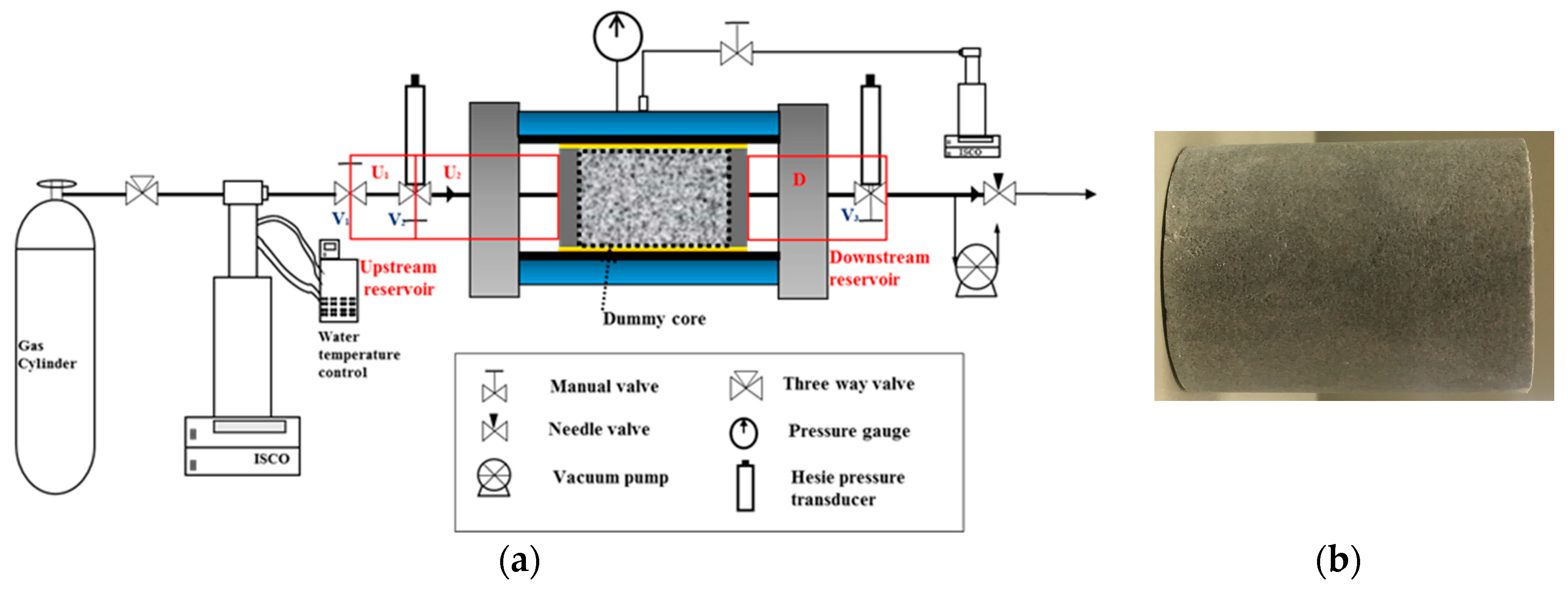
Figure 2a shows three components of the pulse-decay set-up and Figure 2b shows the core plug. The upstream reservoir is installed at the core inlet which is composed of two parts: the first upstream reservoir U1 and the second upstream reservoir U2. The downstream reservoir, D, is installed at the core outlet. Volumes of U1, U2 + D are measured based on Boyle’s law after connecting the two end caps directly. Afterwards, a dummy core without porosity is placed between two end caps to measure the volume of U2. After obtaining all the volumes of the reservoirs, the pore volume of the core can be measured conveniently based on Boyle’s law.
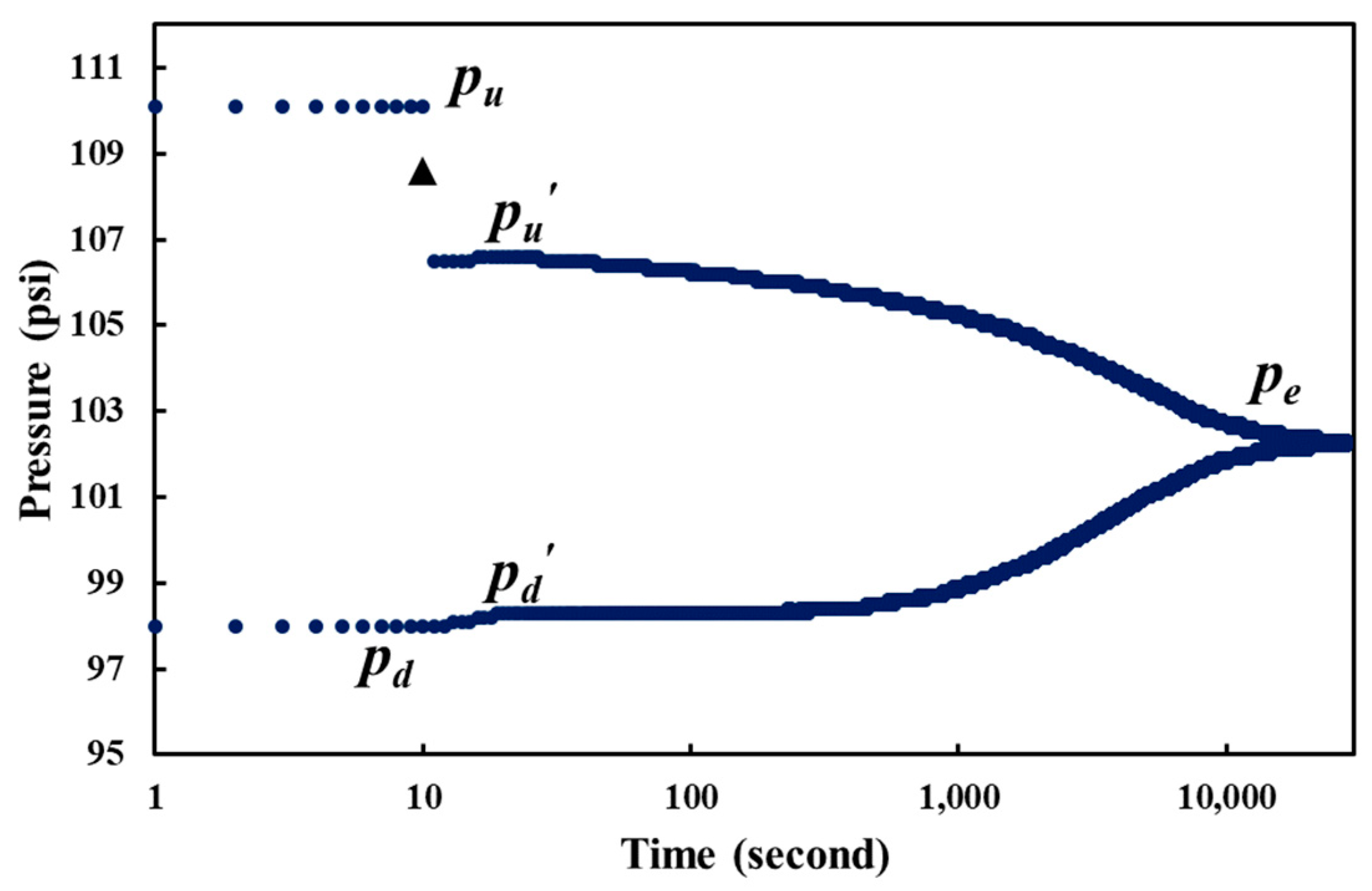
Figure 3 shows an example of the entire pressure curves in a pulse decay experiment on one core sample without fractures. Initially, the core sample and downstream are saturated with nitrogen under pressure of 98 psi (pd), and the first upstream reservoir is saturated with nitrogen under pressure of 110.1 psi (pu). Valve V1 is opened at the 10th second. Nitrogen expands freely to the second upstream reservoir and flows into the core inlet. Heise pressure transducers in this set-up record data point every second. Upstream reservoir pressure drops abruptly at the 11th second. It firstly drops to the lowest point and then increases slightly to 106.6 psi (pu’) due to the Joule–Thomson effect. At the same time, a pressure spike in the downstream is also observed. The downstream pressure is increased to 98.3 psi (pd) after about 10 seconds. We recorded the reduced pressure as the triangular point after replacing the core with the dummy core under the same initial conditions. In experiments under all the pressures, the triangular point is compared against the reduced pressure, which uses the volume of U1 and U2 and pressure conditions based on the Boyle’s law. This practice validates the accuracy of the volume of U1 and U2 involved in the calculations and numerical modeling. The validation is important because the volumes are very small that they need to be precise for the result reliability. It is found that the reduced pressure is higher than pu’. Besides, the pressure decline from the triangular point to pu’ is accomplished only in one second; and pressure spike at the downstream needs longer time, about 10 seconds. We propose that the behaviors of pu’ and pd are reasons that the early-time solution yields much higher permeability values than the later solution, as observed by previous researchers [23,24,25,26].
In addition, we suggest that preferential flow path and secondary accessible flow path correspond to the early-time solution and late-time solution, respectively; the volume sum of them could be estimated by Equation (2) and the volume of the secondary accessible flow path could be estimated by Equation (3).
p u V u 1 Z u + p d ( V u 2 + V p + V d ) Z d = p e ( V u 1 + V u 2 + V p + V d ) Z e
p u ( V u 1 + V u 2 ) Z u + p d ( V p + V d ) Z d = p e ( V u 1 + V u 2 + V p + V d ) Z e
= V p V b
= V p V b
Zu, Zd and Ze are compressibility factors of upstream pressure, downstream pressure and equilibrium pressure, respectively. Vp is the pore volume, Vb is the bulk volume and ϕ is the porosity. The two methods using Boyle’s law could be employed to calculate porosity. The superscript “’” indicates that the second method using Equation (3) is applied. Equation (2) is formed based on the pressure of pu, pd, and pe, and Equation (3) is formed based on the pressure of pu’, pd, and pe. Vu1, Vu2, and Vd are volumes of the first upstream reservoir, second upstream reservoir and downstream reservoir, and the values are 3.147 cm3, 0.431 cm3, and 3.183 cm3, respectively. Table 2 lists the corresponding compressibility factors under the specific pressures and 86 °F.
Intuitively speaking, porosity values estimated from Equations (4) and (5) should be the same. The estimated porosity using pu and pd (Equation (4)), pu’ and pd (Equation (5)), and with the forward and backward flow directions under all the pressures will be compared.
Continuous tests were performed by increasing the pore pressure from low to high. The effective stress is kept constant under 2000 psi by controlling the confining pressure. The pulse size is controlled as about 10% of the pore pressure. After reaching the pore pressure of approximately 300 psi, the pressure in the system is relieved, and the core sample is reverted and placed in the core holder to repeat the experiment under the same pressure. We obtained the permeability by history-matching pressure curves starting from the point that pressure begins to decrease after the Joule–Thomson effect. We applied the black oil simulator, IMEX, which is the black oil simulator of CMG [27] to simulate the process. Nitrogen viscosity and density from NIST database [28] were used as input for the fluid properties. Configurations of the core diameter and length, upstream and downstream reservoir volumes and core porosity were also given in the simulator. CMOST [29] was used to tune the core permeability with the range of 1 nD to 0.1 mD to match the pressure curves. We set the simulation experiments number as 500, and the case with the least matching error was regarded as the fitting result.

3. Results and Discussion

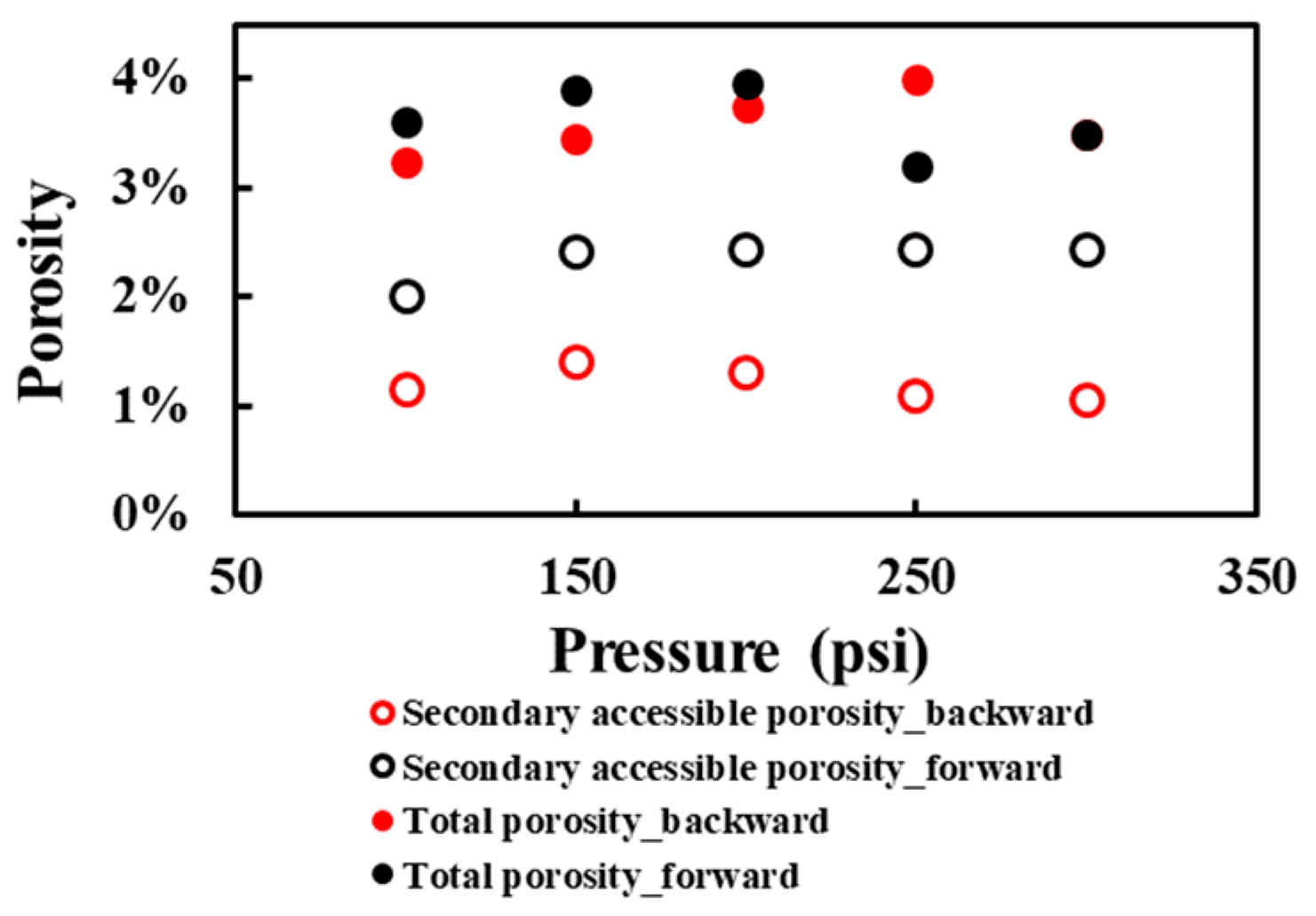
Based on the pressure responses during the test, we suggest that the preferential flow path exists in a natural, tight and heterogeneous core even if a microcrack is not present. Gas will choose different flow paths through the core from upstream to downstream. The flow path is preferential if it is less tortuous and with higher permeability. On the other hand, the flow path is described as secondarily accessible when the tortuosity increases and permeability decreases. We examined closely the intact pressure curves throughout the experiment and found that gas flow in the preferential flow path occurs at the very beginning of the pulse-decay experiment, which finishes within one second based on our observation, and it is much faster than that in the secondary accessible flow path. Thus, the concepts of total and secondary accessible porosity, estimated from Equations (4) and (5), respectively, are proposed in this work to differentiate the two types of the flow path.
Figure 4 shows two types of porosity calculated from the test at different pressures. A significant difference exists between the total porosity and secondarily accessible porosity during the pressure range from 100 psi to 300 psi. Total porosity is approximately 3.5% for both forward and backward directions, which is in accordance with the NMR porosity (3.7%). The small difference (0.2%) might be due to the free water amount in the vuggy pores on the surface in the NMR experiment. Secondarily accessible porosity is averagely 1.2% and 2.3% in the forward and backward directions, respectively; the difference is because pu’ is lower in the forward direction, which is caused by the heterogeneity characteristic of the core. Therefore the preferential accessible porosity is 2.3% and 1.0% in the forward and backward directions, respectively. This implies that the volumes of the preferential and secondarily accessible path are also direction-dependent because of core heterogeneity.
Table 3 records the experimental details of all the tests performed, including initial pressures in the upstream and downstream, flow direction, porosity and permeability results from history matching.
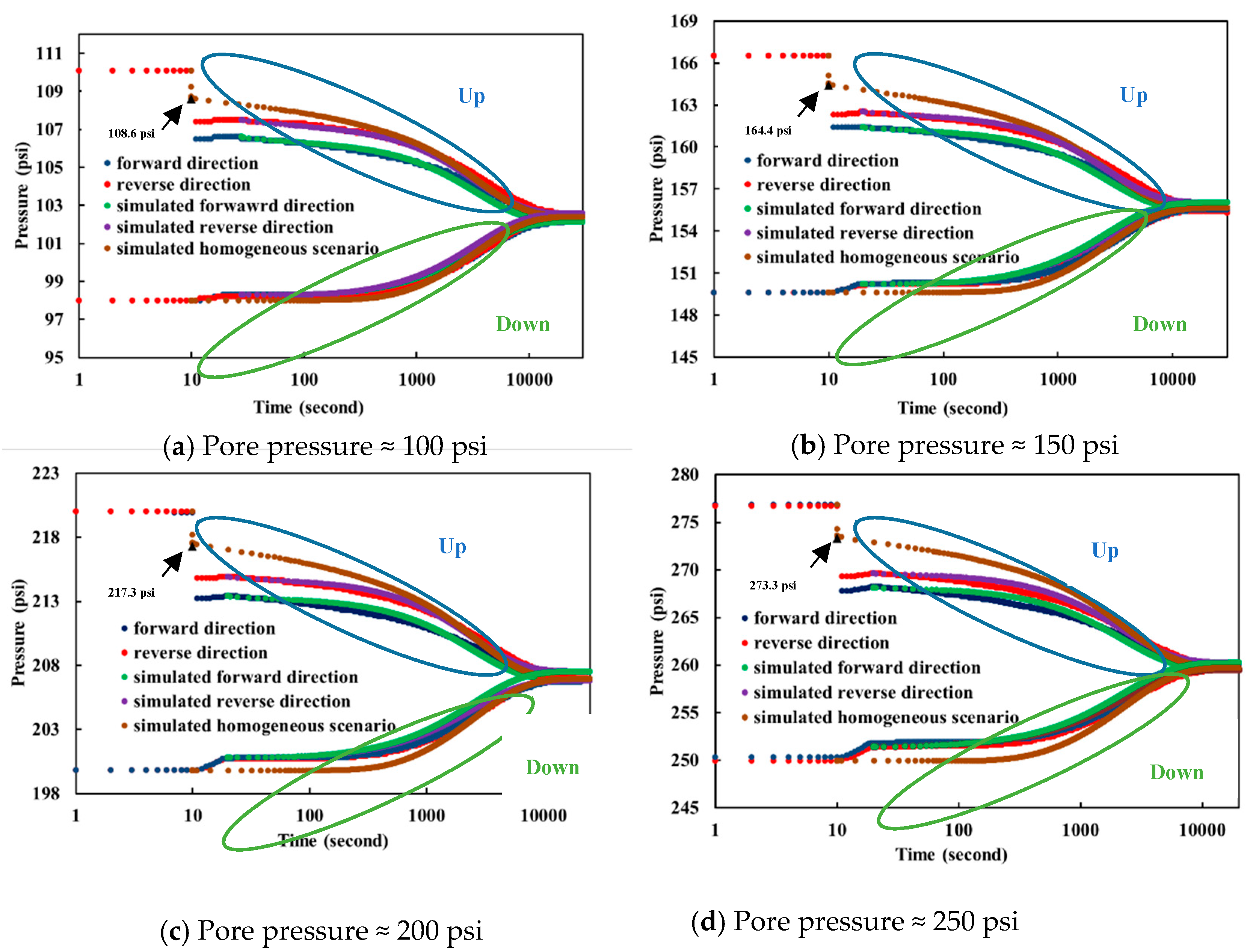
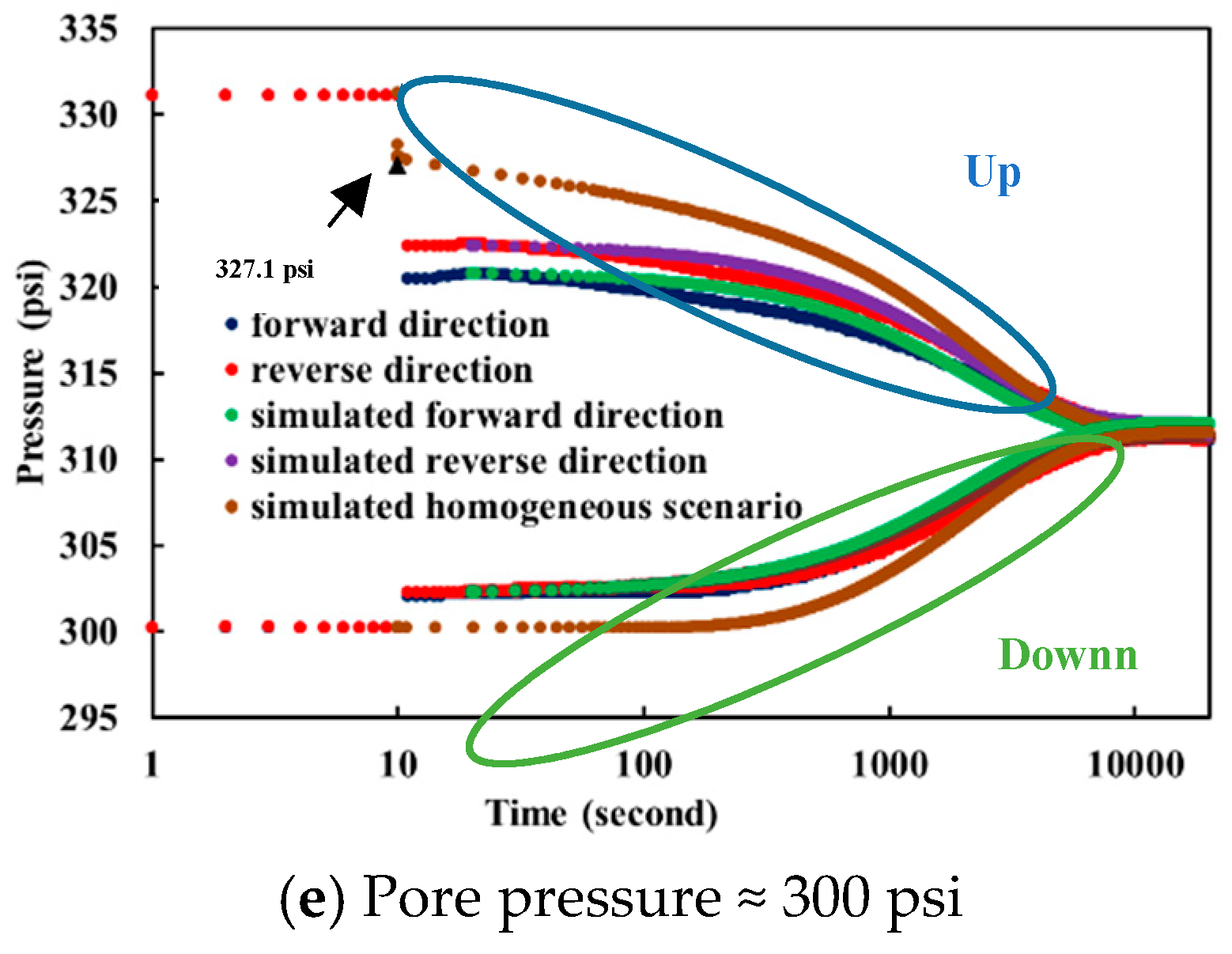
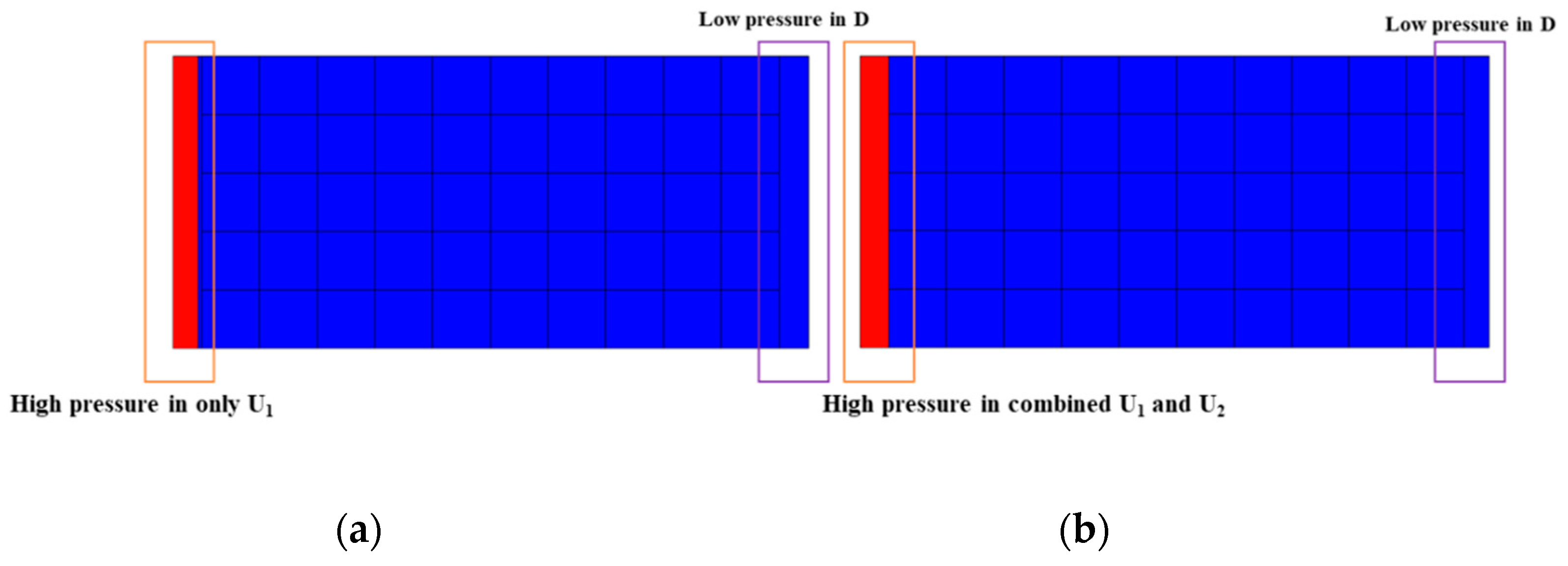
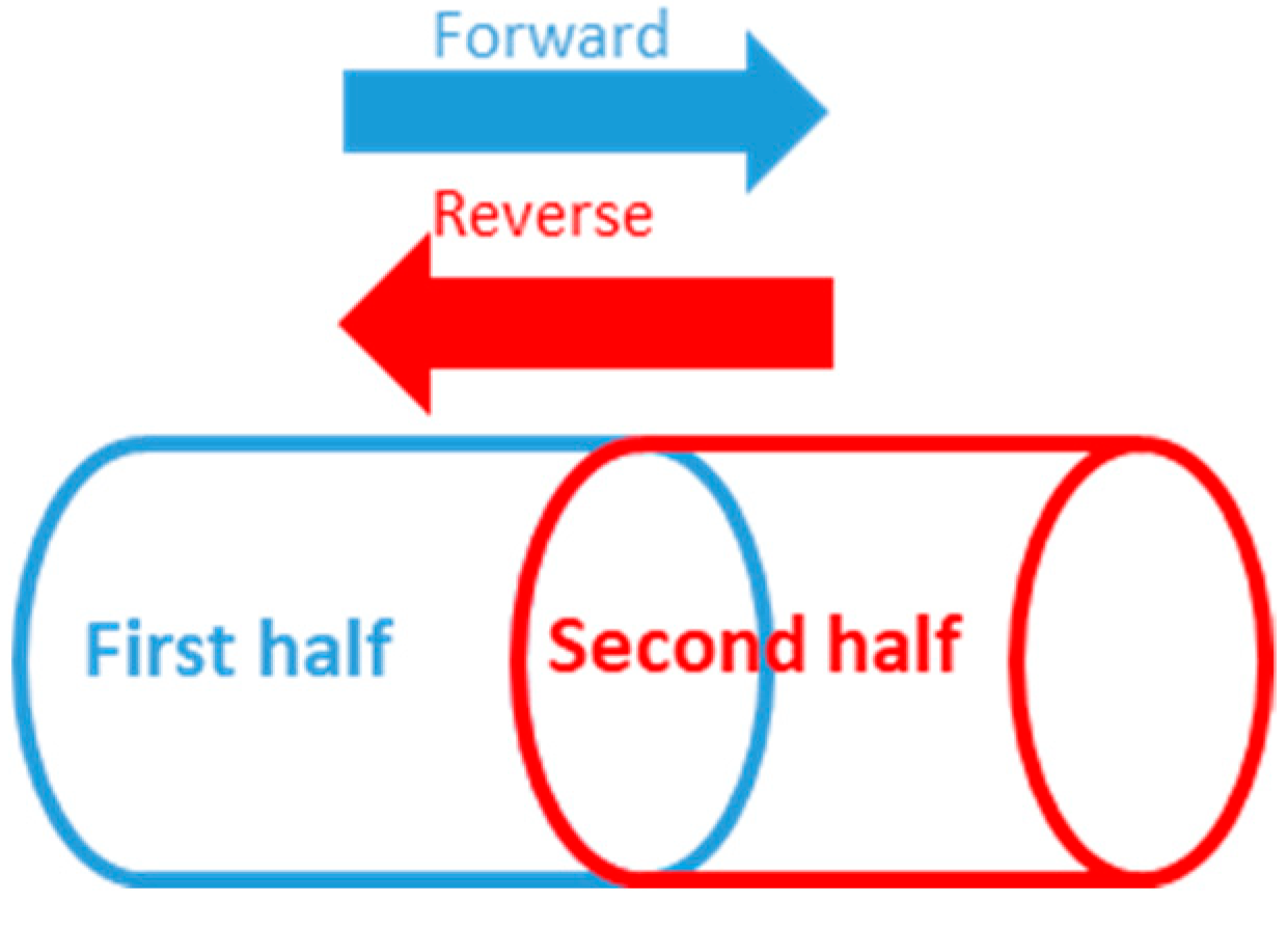
Figure 5 shows experimental and simulated pressure curves under the initial pore pressures approximately of 100 psi, 150 psi, 200 psi, 250 psi and 300 psi of flowing gas from the forward and backward directions. The test durations are about 3 hours for this sample under the current experimental operating conditions with pulse size about 10% of the initial pore pressure. The test duration depends on many factors, including the gas pressure, volumes of the downstream and upstream reservoirs, pulse size, etc. Figure 6 shows the simulation scenarios. The model used for history matching to obtain permeability is (b), and the model (a) is used to obtain the pressure curves from the ideal (homogeneous) scenarios using the mean permeability of the forward and backward flow history matching results. Pressure curves (Figure 5) are shifted regarding the experiment start time for better comparison purposes: the system is under equilibrium in the first 10 seconds, and the experiment starts at the end of 10th second. The pressure at the 11th second in the forward direction (blue) is lower than in the backward direction (red) in all experiments. This fact indicates that pressure propagation through the core is flow direction dependent: it is easier for gas transport in the first half of the core, which directly implies heterogeneity of the core sample that the first half of it is more permeable than the second half (Figure 7), supported by the higher porosity values reported in the backward (reverse) direction than the forward direction in Figure 4 and Table 3.
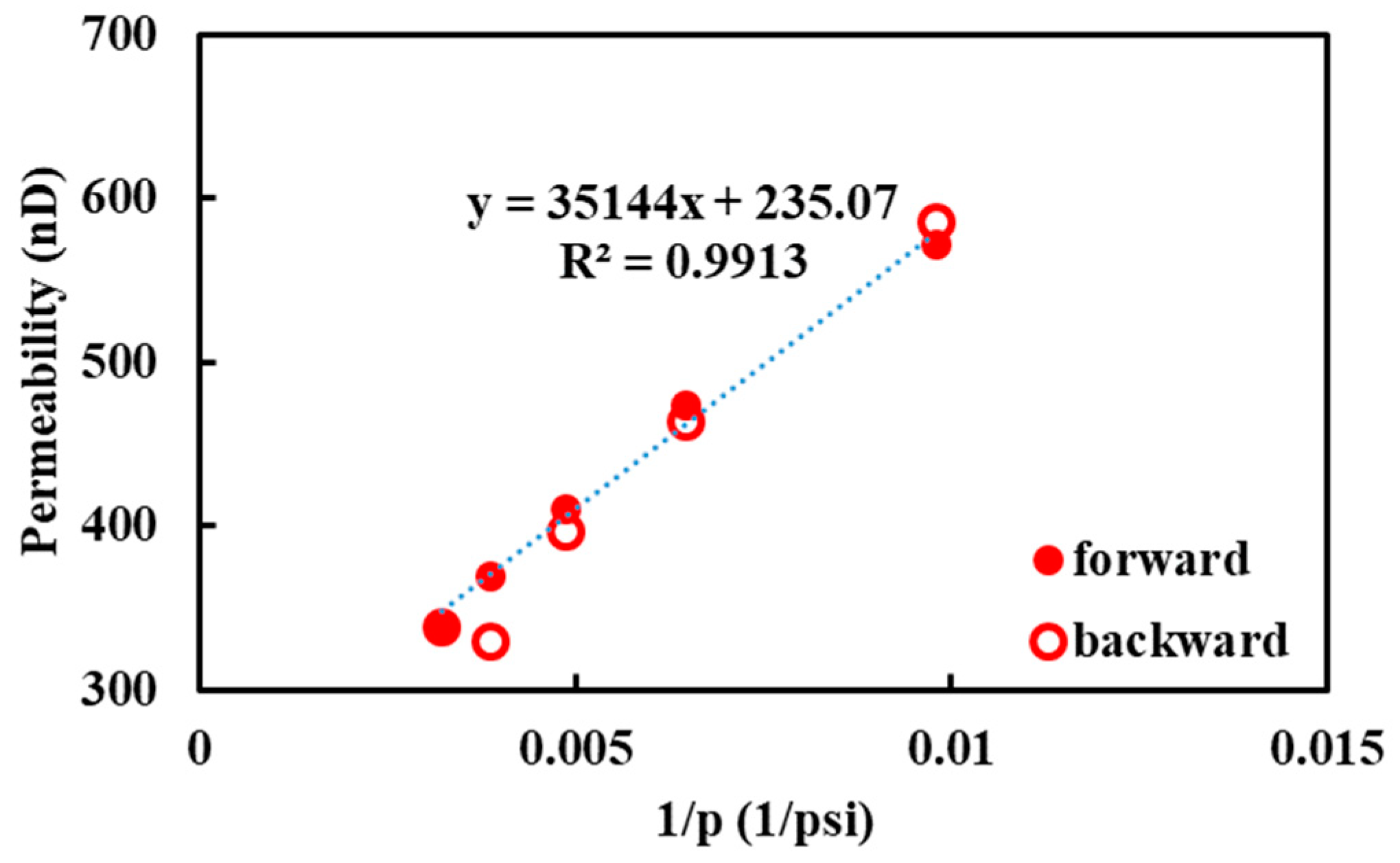
Figure 8 shows the matched permeability values as a function of the inverse of pore pressures. A first-order Klinkenberg equation is used to fit the permeability curve as a function of the inverse of pore pressure. k is the intrinsic permeability independent of flowing conditions which is 235 nD. b is the slippage factor which is 150 psi.
k = k ( 1 + b p )
The matched permeability does not differ significantly in the forward and backward flow directions, indicating the preferential flow path mainly affects the early-stage pressure propagation and fluid flow processes. The matched permeability ranges approximately from 300 nD (3 × 10⁻⁴ mD) and 600 nD (6 × 10⁻⁴ mD) through the pressure range. Gas permeability is higher in the low-pressure range due to the gas slippage effect.
By using the matched permeability, an idealized homogeneous scenario is obtained starting from the initial pressure pu and pd (reduced pressure using dummy core). The simulated pressure curves in homogeneous scenarios are different from the forward and backward flow-matched curves is because (1) ideal gas is applied so that no Joule–Thomson will affect the fluid flow and (2) the starting point of the pressure simulations are different as shown in Figure 6. The three sets of simulated pressure curves share almost the same permeability and reach the final equilibrium pressure almost at the same time. However, as the permeability in the preferential flow path is much higher than that in the secondary flow path based on the fact that the pressure decrease in the preferential finishes within one second. We could reasonably infer that purely estimating permeability starting at pu’ and pd significantly underestimates both porosity and permeability.
By comparing Figure 5a to Figure 5e it is found that the preferential flow path is more significant under higher pressure. As pore pressure increases, a larger deviation of pu’ from the reduced pressure by the dummy core is observed. A more rapid pressure spike is observed downstream, as the difference between pd and pd becomes more pronounced and the time for pd to reach pd is shorter and shorter. For example, in the 300 psi scenario, 300.2 psi increases to 302.3 psi within only one second that this process takes longer under lower pressure.
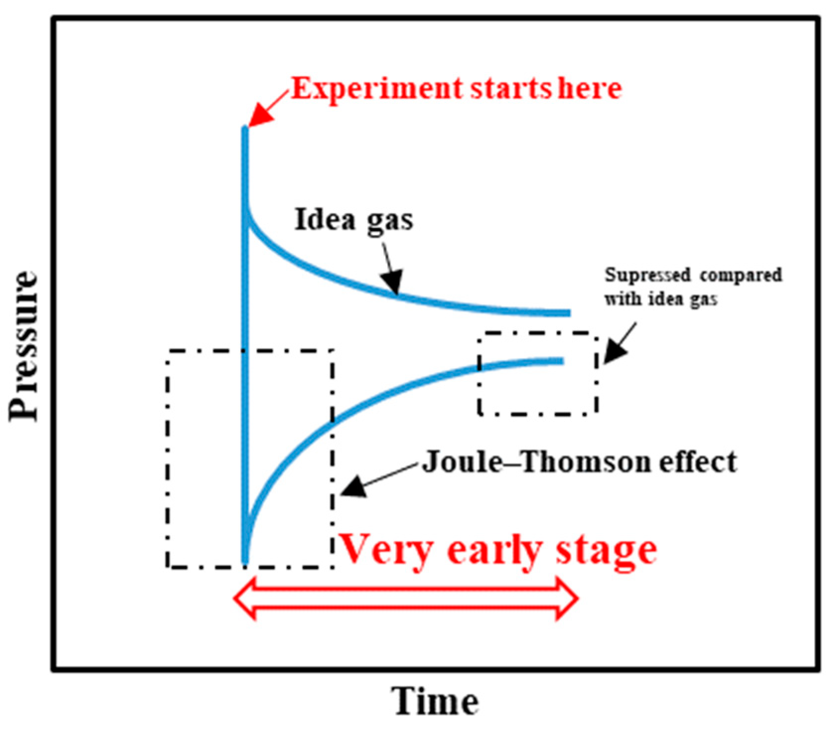
Figure 9 shows a conceptual pressure plot in the upstream at the very early stage of the experiment. Because of the Joule-Thomson effect, when gas expands from high pressure to low pressure that the volume expands, the local temperature changes cause the over-reduced pressure immediately. Correspondingly, the downstream reservoir reacts to the pressure change in the upstream reservoir, as shown in Figure 5. However, the temperature will be quickly warmed up due to the constant temperature control of the oven, and the pressure will increase in response to the temperature change. Due to the fact that the gas pressure recovery caused by Joule–Thomson takes time, and the fact that gas propagates to the lower-pressure pore volume in the core and upstream reservoir at the same time, the upstream pressure curve will behave suppressed compared with the ideal gas without Joule–Thomson effect. High frequently data logging is helpful to capture the early-stage pressure response. In our experiment, recording frequency is every 1 second, which captures the instant response after opening the value to start the experiment as shown in Figure 5 but a higher frequency recording system could be expected to record more reduced pressure during the first second after starting the experiment.
Figure 10 shows the process of constant pressure injection to elevate the system pressure to 98 psi, which is the starting point in Figure 5. Prior to the constant pressure injection, vacuuming is applied to excavate air in the system. Therefore, the initial downstream and pore pressure is below the atmospheric pressure. The pressure pulse between the upstream and downstream is more than 100 psi, which is much larger than the experiments in Figure 5. However, unlike the scenario that pore space is already under a certain level of pressure, no pressure spike is observed instantaneously at the downstream reservoir, even though the pressure pulse is more than 100 psi. This observation implies that the preferential flow path forms in the tight porous media only under elevated pore pressure but not below atmospheric pressure. The possible explanation is that when the downstream and core are under (or close to) vacuuming state, negligible gas is saturated in the pore network, causing a pressure response that is not immediate even though there is a pressure differential of about 100 psi between the upstream and downstream.

4. Conclusions

The following conclusions are obtained from this study:
  • The preferential flow path exits in a natural, tight and heterogeneous core even when a microcrack is not present.
  • Transient gas flows through the preferential flow path at the very beginning. Failing to take the early pressure response into account leads to significant underestimation of porosity and permeability.
  • The formation of a preferential flow path in heterogeneous porous media is more pronounced under an elevated pore pressure.
  • Performing a pulse-decay experiment in both the forward and backward directions assists differentiating which part of the core is more permeable.

Author Contributions

Conceptualization, B.J.; Methodology, B.J.; Formal analysis, B.J. and F.Z.; Investigation, B.J. and F.Z.; Writing—original draft, B.J. and F.Z.; Writing—review & editing, J.-S.T. and R.B.; Supervision, J.-S.T. and R.B.

Funding

This research was funded by Tertiary Oil Recovery Program (TORP) at the University of Kansas (no grant number provided). We are grateful to the technical support from Mr. Scott Ramskill, and the core sample from Kansas Geological Survey (KGS). The manuscript was partially presented at the International Symposium of the Society of Core Analysts held in Vienna, Austria in 2017.

Conflicts of Interest

The authors declare no conflict of interest.

References

  1. Wojnarowski, P.; Czarnota, R.; Janiga, D.; Stopa, J. Novel liquid-gas corrected permeability correlation for dolomite formation. Int. J. Rock Mech. Min. Sci. 2018, 112, 11–15. [Google Scholar] [CrossRef]
  2. Al-Jabri, R.A.; Al-Maamari, R.S.; Wilson, O.B. Klinkenberg-corrected gas permeability correlation for Shuaiba carbonate formation. J. Pet. Sci. Eng. 2015, 131, 172–176. [Google Scholar] [CrossRef]
  3. Tanikawa, W.; Shimamoto, T. Correction to “comparison of Klinkenberg-corrected gas permeability and water permeability in sedimentary rocks”. Int. J. Rock Mech. Min. Sci. 2009, 46, 1394–1395. [Google Scholar] [CrossRef]
  4. Han, G.; Chen, Y.; Liu, M.; Liu, X. Differences in Performance of Models for Heterogeneous Cores during Pulse Decay Tests. Appl. Sci. 2019, 9, 3206. [Google Scholar] [CrossRef]
  5. Han, G.; Chen, Y.; Liu, X. Investigation of analysis methods for pulse decay tests considering gas adsorption. Energies 2018, 12, 2562. [Google Scholar] [CrossRef]
  6. Feng, R. An optimized transient technique and flow modeling for laboratory permeability measurements of unconventional gas reservoirs with tight structure. J. Nat. Gas Sci. Eng. 2017, 46, 603–614. [Google Scholar] [CrossRef]
  7. Feng, R.; Harpalani, S.; Saurabh, S. Experimental investigation of in situ stress relaxation on deformation behavior and permeability variation of coalbed methane reservoirs during primary depletion. J. Nat. Gas Sci. Eng. 2018, 53, 1–11. [Google Scholar] [CrossRef]
  8. Brace, W.F.; Walsh, J.B.; Frangos, W.T. Permeability of granite under high pressure. J. Geophys. Res. Space Phys. 1968, 73, 2225–2236. [Google Scholar] [CrossRef]
  9. Hsieh, P.; Tracy, J.; Neuzil, C.; Bredehoeft, J.; Silliman, S. A transient laboratory method for determining the hydraulic properties of ‘tight’ rocks—I. Theory. Int. J. Rock Mech. Min. Sci. Géoméch. Abstr. 1981, 18, 245–252. [Google Scholar] [CrossRef]
  10. Ning, X. The Measurement of Matrix and Fracture Properties in Naturally Fractured Low Permeability Cores Using a Pressure Pulse Method. Ph.D. Thesis, Texas A&M University, College Station, TX, USA, 1992. [Google Scholar]
  11. Dicker, A.I.; Smits, R.M. A practical approach for determining permeability from laboratory pressure-pulse decay measurements. In Proceedings of the International Meeting on Petroleum Engineering, Tianjin, China, 1–4 November 1998. SPE-17578-MS. [Google Scholar]
  12. Cui, X.; Bustin, A.M.M.; Bustin, R.M.; And, A.M.M.B. Measurements of gas permeability and diffusivity of tight reservoir rocks: Different approaches and their applications. Geofluids 2009, 9, 208–223. [Google Scholar] [CrossRef]
  13. Jia, B.; Tsau, J.-S.; Barati, R. Different Flow Behaviors of Low-Pressure and High-Pressure Carbon Dioxide in Shales. SPE J. 2018, 23, 1452–1468. [Google Scholar] [CrossRef]
  14. Kamath, J.; Boyer, R.; Nakagawa, F. Characterization of Core Scale Heterogeneities Using Laboratory Pressure Transients. SPE Form. Eval. 1992, 7, 219–227. [Google Scholar] [CrossRef]
  15. Cronin, M.B. Core-Scale Heterogeneity and Dual-Permeability Pore Structure in the Barnett Shale. Master’s Thesis, University of Texas, Austin, TX, USA, 2014. [Google Scholar]
  16. Bhandari, A.R.; Flemings, P.B.; Polito, P.J.; Cronin, M.B.; Bryant, S.L. Anisotropy and Stress Dependence of Permeability in the Barnett Shale. Transp. Porous Media 2015, 108, 393–411. [Google Scholar] [CrossRef]
  17. Alnoaimi, K.R. Influence of Cracks and Microcracks on Flow and Storage Capacities of Gas Shales at Core-Level. Ph.D. Thesis, Stanford University, Stanford, CA, USA, 2016. [Google Scholar]
  18. Lin, W. Compressible fluid flow through rocks of variable permeability. In Compressible Fluid Flow through Rocks of Variable Permeability; Lawrence Livermore Laboratory: Livermore, CA, USA, 1977; Available online: https://inis.iaea.org/collection/NCLCollectionStore/_Public/09/368/9368401.pdf (accessed on 8 September 2018).[Green Version]
  19. Jones, S. A Technique for Faster Pulse-Decay Permeability Measurements in Tight Rocks. SPE Form. Eval. 1997, 12, 19–26. [Google Scholar] [CrossRef]
  20. Civan, F.; Rai, C.S.; Sondergeld, C.H. Intrinsic shale permeability determined by pressure-pulse measurements using a multiple-mechanism apparent-gas-permeability non-Darcy model. In Proceedings of the SPE Annual Technical Conference and Exhibition, Florence, Italy, 19–22 September 2010. SPE-135087-MS. [Google Scholar]
  21. Dunham, R.J. Classification of Carbonate Rocks according to Depositional Textures; American Association of Petroleum Geologists, 1962; Available online: https://pubs.geoscienceworld.org/books/book/1475/chapter/107178011/classification-of-carbonate-rocks-according-to (accessed on 16 September 2019).
  22. Franseen, E.K.; Byrnes, A.P.; Cansler, J.R.; Carr, T. The geology of Kansas: Arbuckle group. In Kansas Geological Survey; Arbuckle Group: Lawrence, KS, USA, 2004; pp. 1–43. [Google Scholar]
  23. Bourbié, T.; Walls, J. Pulse Decay Permeability: Analytical Solution and Experimental Test. Soc. Pet. Eng. J. 1982, 22, 719–721. [Google Scholar] [CrossRef]
  24. Walder, J.; Nur, A. Permeability measurement by the pulse-decay method: Effects of poroelastic phenomena and non-linear pore pressure diffusion. Int. J. Rock Mech. Min. Sci. Géoméch. Abstr. 1986, 23, 225–232. [Google Scholar] [CrossRef]
  25. Sander, R.; Pan, Z.; Connell, L.D. Laboratory measurement of low permeability unconventional gas reservoir rocks: A review of experimental methods. J. Nat. Gas Sci. Eng. 2017, 37, 248–279. [Google Scholar] [CrossRef]
  26. Jia, B.; Tsau, J.-S.; Barati, R. Experimental and numerical investigations of permeability in heterogeneous fractured tight porous media. J. Nat. Gas Sci. Eng. 2018, 58, 216–233. [Google Scholar] [CrossRef]
  27. IMEX. IMEX User Guide, Three-Phase, Black-Oil Reservoir Simulator; IMEX: Calgary, AB, Canada, 2016. [Google Scholar]
  28. Lemmon, E.W.; Huber, M.L.; McLinden, M.O. NIST Reference Fluid Thermodynamic and Transport Properties—REFPROP; NIST Standard Reference Database: Gaithersburg, MD, USA, 2013. [Google Scholar]
  29. CMOST. CMOST User Guide, Enhance & Accelerate Sensitivity Analysis, History Matching, Optimization & Uncertainty Analysis; CMOST: Calgary, AB, Canada, 2016. [Google Scholar]
Figure 1. (a) X-ray powder diffraction (XRD) result of the sample and (b) pore size distribution of the core sample based on the nuclear magnetic resonance (NMR) result.
Energies 12 03559 g001
Figure 2. (a) Pulse-decay experimental set-up and (b) the core sample for the test.
Energies 12 03559 g002
Figure 3. Pressure data points in estimating total porosity and secondary accessible porosity in a pulse-decay experiment.
Energies 12 03559 g003
Figure 4. Total porosity and secondarily accessible porosity in the core in the forward and backward directions. Note the pressures are approximated beginning at 100 psi and with a step of 50 psi.
Energies 12 03559 g004
Figure 5. Experimental and simulated pressure curves in the pulse-decay experiment. Experiment results include pressure curves by flowing nitrogen in the forward and backward directions, pressure ranges from 100 psi to 300 psi (from (a) to (e)). The pressure curve is adjusted within ± 0.2 psi using the same initial downstream pressure pd for better visualization of comparing pressure responses in different directions. Simulated pressure curves are generated by matching the late-time pressure response using the secondary accessible porosity, and the homogeneous scenarios are constructed based on the averaged permeability obtained from the matching results using the total porosity. The black triangle point is the reduced experimental pressure after gas freely expands from the first upstream reservoir to the second upstream reservoir if a dummy core replaces the natural core sample.
Energies 12 03559 g005aEnergies 12 03559 g005b
Figure 6. Simulation models composed of the high-pressure upstream (red) and low-pressure downstream (blue) as enclosed by the squares. In the middle of upstream and downstream is the core. (a) Ideal case (homogeneous) simulation model using average permeability values of the forward and backward flow history matchings with only U1 under high pressure. (b) History matching simulation model using experimental data with combined U1 and U2, with the initial upstream pressure of pu’ and the initial downstream pressure of pd, as illustrated in Figure 2.
Energies 12 03559 g006
Figure 7. Schematic showing the first and second halves of the core sample and flow directions.
Energies 12 03559 g007
Figure 8. History matching results under different pore pressure in the forward and backward flow directions.
Energies 12 03559 g008
Figure 9. Conceptual pressure plot in the upstream illustrating the influence of Joule–Thomson effect on the pressure response.
Energies 12 03559 g009
Figure 10. Constant pressure gas injection to form gas saturation in the pulse-decay set-up.
Energies 12 03559 g010
Table 1. Representative work regarding the pulse-decay method in tight cores.
AuthorContribution
Brace et al. [8]Firstly applied pulse-decay method to measure the permeability of granite
Lin [18]Put forward the basic numerical model for the pulse-decay process
Hsieh et al. [9]Presented complete and restrictive analytical solution for pulse-decay process
Dicker and Smits [11]Simplified the complete analytical solution with acceptable accuracy
Kamath et al. [14]Characterized heterogeneity and microcrack of synthetic cores using the pulse-decay method
Ning [10]Explored dual porosity and dual permeability of fractured cores analytically and numerically
Jones [19]Proposed valuable recommendations for pulse-decay experimental set-up design, for example, using cores with a large diameter and short length
Cui et al. [12]Extended the flowing fluid from non-adsorptive gas to adsorptive gas
Civan et al. [20]Incorporated other important variables in the numerical settings of pulse-decay
Cronin [15]Numerically explained the impacts of anisotropy and microcrack on the pulse-decay pressure response
Bhandari et al. [16]Measured vertical and horizontal permeability of the Barnett shale
Alnoaimi [19]Numerically matched pressure curves of non-adsorptive gas and adsorptive gas during a pulse-decay experiment
Jia et al. [13]Comprehensively investigated flow behaviors of adsorptive and non-adsorptive gas in a wide range of pressure in a tight core using the pulse-decay method
Table 2. Pressure and compressibility factor of data points in Figure 3.
Propertiespupdpupdpe
Pressure, psig110.198106.698.3102.3
Compressibility factor, Z0.99890.99900.99900.99900.9990
Table 3. Experimental details of each test ranging approximately from 100 psi to 300 psi.
Properties100100150150200200250250300300
Initial upstream pressure pu (psi)106.5107.5161.4162.5213.4214.9268.2271.3320.8322.5
Initial downstream pressure pd (psi)98.398.2150.1150.2200.7200.7251.4251.2302.2302.4
Initial pressure differential (pupd) (psi)8.29.311.312.312.714.216.820.118.620.1
Initial pressure differential (pu − pd) (psi)12.1 12.116.916.920.220.226.927.230.830.8
Flow directionForwardBackwardForwardBackwardForwardBackwardForwardBackwardForwardBackward
Secondarily accessible porosity (%)1.22.01.42.41.32.41.12.41.12.4
Permeability (nD)572.5586.0473.5464.5410.5397.0370.0329.5338.5338.5