Article

Performance Analysis of Synchronous Reluctance Motor with Limited Amount of Permanent Magnet

1
Department of Systems and Naval Mechatronic Engineering, National Cheng Kung University, Tainan 70101, Taiwan
2
Department of Electrical Engineering, National Cheng Kung University, Tainan 70101, Taiwan
*
Author to whom correspondence should be addressed.
Energies 2019, 12(18), 3504; https://doi.org/10.3390/en12183504
Submission received: 11 August 2019 / Revised: 6 September 2019 / Accepted: 9 September 2019 / Published: 11 September 2019
(This article belongs to the Special Issue Advances in Rotating Electric Machines)

Abstract

:
This paper analyzes the performance of a synchronous reluctance motor (SynRM) equipped with a limited amount of a permanent magnet (PM). This is conventionally implemented by inserting PMs in rotor flux barriers, and this is often called the PM-assisted SynRM (PMa-SynRM). However, common PMa-SynRMs could be vulnerable to irreversible demagnetization. Therefore, motor performance and PM demagnetization should be simultaneously considered, and this would require the PM to be properly arranged. In this paper, various rotor configurations are carefully studied and compared in order to maximize the motor performance, avoid irreversible demagnetization and achieve higher PM utilization. Moreover, the field weakening capability is investigated and improved by regulating armature excitation. A particular rotor type with flux intensification was found to possess higher PM utilization, lower demagnetization possibility with fairly high performance. Thus, suitable rotor configurations are recommended for certain applications.

1. Introduction

The synchronous reluctance motor (SynRM), with its robustness, high overload capability and low cost, has become a popular research target for many years [1,2,3,4]. However, the relatively lower torque/power density and power factor are the inherent disadvantages of SynRMs [5,6,7] compared to a permanent magnet synchronous machine (PMSM). To overcome such weaknesses, a permanent magnet (PM) can be inserted into the rotor of the SynRMs with a modest volume, which leads to the birth of a type of motor called the permanent magnet assisted synchronous reluctance motor (PMa-SynRM) [8,9,10,11]. With the increasing number of related research works, the PMa-SynRM has become a popular choice in some applications and can be an alternative to a SynRM or PMSM [12,13,14,15].
Generally, the PMs inserted inside the rotor flux barriers produce a negative flux linkage along the q-axis. The q-axis inductance Lq is usually low due to the multiple flux barriers. The permanent magnet (PM) flux linkage (the flux linkage due to PM solely) promotes the rotation of the flux linkage vector, and therefore the voltage vector goes close to the current vector to increase the power factor [9]. The PM flux linkage also contributes to torque production so that the total torque increases. However, the volume/size of the added PM needs to be limited to avoid the motor becoming an interior permanent magnet synchronous motor (IPMSM) [16], which could also increase the cost. Nevertheless, the volume/size of the PM should not be too small to achieve the desired torque and power density, or to be vulnerable to irreversible demagnetization [10].
For SynRMs or PMa-SynRMs, various design possibilities can be considered, e.g., the number of flux barriers, with or without PMs, rare earth or other types of PM materials or the amount of PM employed. In an effort to standardize the design process of SynRMs and PMa-SynRMs, Bianchi et al. [11] proposed a series of steps that are synthesized from some example studies [11,17,18,19,20], where the inward PMs (near the rotor shaft) are larger than the outward ones to improve flux flows and avoid demagnetization. This PM arrangement is considered as a common trend for the PMa-SynRM rotor design.
Some motor designs presented in previous research [10,11,21,22,23] using either rare-earth or ferrite PMs are summarized in Table 1, including their ratio of PM-to-motor volume and torque density. It can be observed that the variety of rotor designs and PM arrangements is rich in these motors. However, the first four motors listed in Table 1 [10,11,21,22] employ a relatively large PM volume compared to the motor studied in Reference [23]. Furthermore, the PM size in the motor in Reference [23] is purposefully made identical for all the PM layers to reduce the manufacturing cost, which is different from common designs. The multiple flux barrier design allows the torque density of this motor to reach 28.1 Nm/L with PM taking only 0.95% of the motor volume by assuming sufficient cooling is applied, as shown in Table 1. However, as mentioned in Reference [16], the low PM volume and high excitation current could lead to its negligible contribution in torque production due to the low PM-torque-to-total-torque ratio and high probability of irreversible demagnetization with field-weakening applied. In addition, since the armature current Is is far from the characteristic current Ich on d-axis [24], the constant power speed range (CPSR) could become relatively low for PMa-SynRM with a little amount of PM. From the above discussions, it is necessary to propose a solution to improve the performance of this type of motor in terms of PM utilization, demagnetization resistivity and field weakening capability.
Therefore, in this paper, several motor models based on a prototyped PMa-SynRM [23] with various PM arrangements using limited amount of PM are analyzed in detail. The analysis concentrates on the effect of the PM position on the magnetic distribution, inductances, torque production, torque/power-speed curves and magnetization characteristics. The armature current is also adjusted for observation on the correlation between the electrical and magnetic parameters affecting the motor performance. From the above analysis, this paper aims to achieve a high PM utilization rate to produce torque though a limited amount of PMs in a more efficient way. Demagnetization can also be avoided under high performance operations. The analysis was conducted using finite element analysis (FEA), which has been partially validated using previous experimental studies [23]. Note that differing from Reference [23], where the evaluation was only conducted for a fixed rotor structure, this paper makes a complete analysis with a sufficient number of models in order to make proper suggestions for the improvement of SynRM performance. In Reference [25], the PM volume was optimized for predetermined field-intensified PM machines. Here, in the present study, the models investigated cover not only conventional PMa-SynRMs, but also the novel flux-intensifying PMa-SynRMs [26]. In what follows, the terms flux-intensification, flux-intensifying and flied-intensified are all abbreviated as FI. In addition, by investigating over an existing prototype, the analysis can be better convincing. The comparisons can also be made to highlight the novelty of the current analysis.
This paper is organized as follows. The mathematical model and the configuration of the motor models are presented first in Section 2. Then, the investigation for the influence of PM positions on motor characteristics is carried out in Section 3, followed by the comparison of some motor models in Section 4. Section 5 presents the discussions over these investigated models. Finally, the paper is concluded by making suggestions for the design of such motors in Section 6.

2. Mathematical Model and Configuration of Investigated Motors

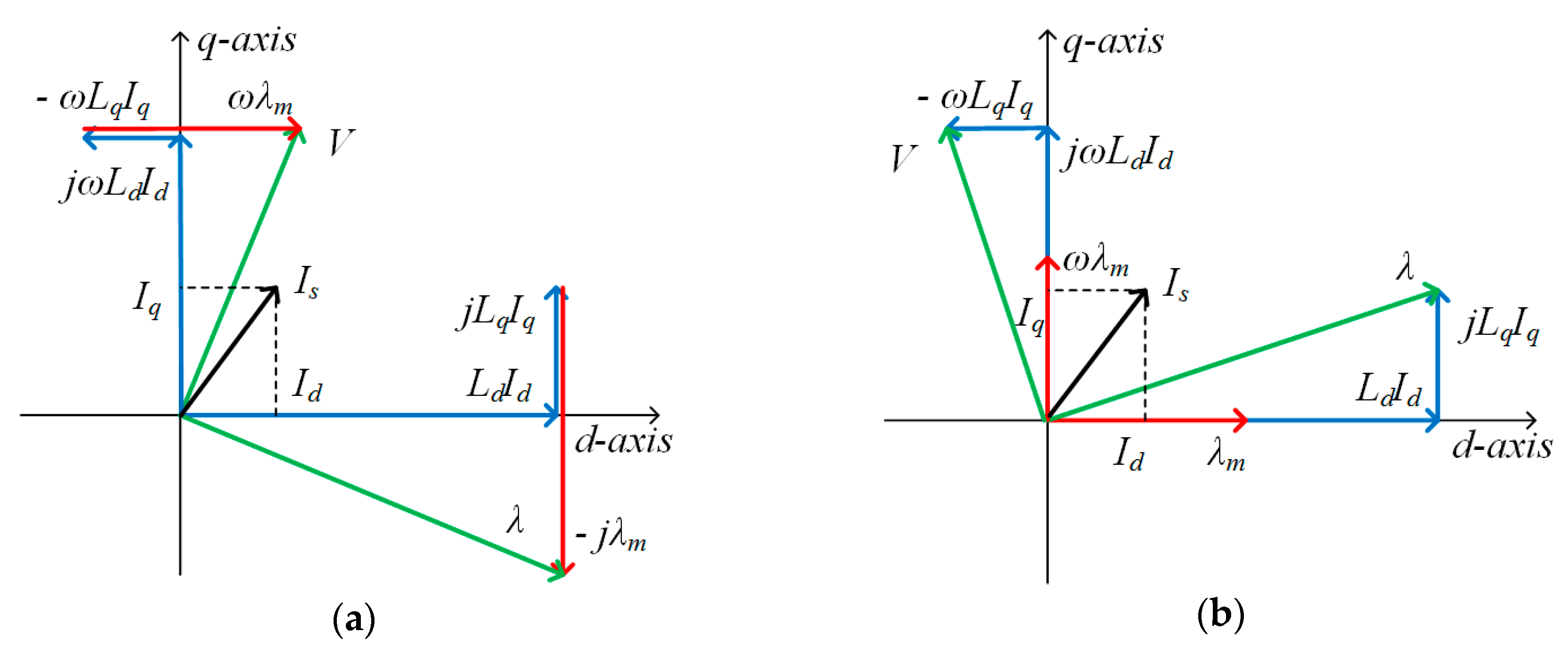
2.1. Mathematical Modeling of Investigated Motors

A conventional SynRM with a limited amount of PM embedded along the flux barriers, i.e., facing the physical q-axis, is called the first PM arrangement (hereafter denoted Type 1), as shown in Figure 1a. In contrast, when PM is added crossing the flux barriers, i.e., facing the d-axis, it is called the second PM arrangement (hereafter denoted Type 2), as the example illustrated in Figure 1b. For the Type 1 rotor, the flux linkage produced by the PM is arranged against the q-axis armature flux linkage, while for the Type 2 rotor, the PM flux linkage complements the d-axis armature flux linkage. The Type 2 motor can thus be called the flux-intensifying PMa-SynRM (FI-PMa-SynRM) [26].
Assuming that the iron saturation and the cross-coupling effect are neglected, the stator dynamic voltage equations for synchronous machines in the d-q frame [27,28] can be expressed as:
v d = R s i d + d λ d d t ω λ q
v q = R s i q + d λ q d t + ω λ d
where the subscripts d and q represent the d- and q-axis, respectively, id and iq are the currents, λd and λd are the flux linkages, Rs is the phase resistance, and ω is the electrical angular speed.
Equations (1) and (2) are general voltage equations for synchronous machines. To be applied to the two types of motors mentioned above, the flux linkages λd and λq in (1) and (2) need to be further discussed since the PMs are arranged differently in these two types of motors. For the Type 1 motors, as previously mentioned, the PMs are arranged in q-axis against the stator flux due to the q-axis current (id), and therefore the flux linkages in the d-q frame can be expressed as:
λ d = L d i d , λ q = L q i q λ m
where Ld and Lq are the stator inductances in the d-q frame, and λm is the PM flux linkage. Note that Ld and Lq do not take into account the PM flux linkage but only the flux linkage produced by id and iq. For the Type 2 motors, the PMs are placed in the d-axis to complement the stator flux and thus the flux linkages are given as:
λ d = L d i d + λ m , λ q = L q i q
From (3) and (4), the flux-weakening nature for the Type 1 motors and the flux-intensifying characteristics for the Type 2 can be clearly observed.
Figure 2 presents the equivalent circuits for the Type 1 [27] and Type 2 motors. As can be seen, the two types of motors have a difference in PM flux linkages. The phasor diagrams for Type 1 [9] and Type 2 are illustrated in Figure 3a,b, respectively, with the winding resistance being neglected [9,29]. Therefore, the voltage equations can be further expressed as:
V = ω ( L d I d ) 2 + ( L q I q λ m ) 2
for Type 1 [30], and:
V = ω ( L d I d + λ m ) 2 + ( L q I q ) 2
for Type 2.
Note that the “-“ sign in front of λm in (3) and (5) indicates that the direction of this quantity is opposing LqIq, differing from the definition in [30].
The torque equations for Type 1 and Type 2 are respectively expressed as:
T = 3 N m 4 [ λ m I d + ( L d L q ) I d I q ]
for Type 1 [29], and
T = 3 N m 4 [ λ m I q + ( L d L q ) I d I q ]
for Type 2 [26].
Figure 4 illustrates the circle diagrams of these two types of motors. For the Type 1 motor with the first PM arrangement shown in Figure 1a, Figure 3a and Figure 4a indicate that the flux linkage generated by the q-axis current could cause the PM to be irreversibly demagnetized, especially for the thin PM. In contrast, for the Type 2 motor with the second PM arrangement shown in Figure 1b, the demagnetization on the PM can be avoided during maximum torque per ampere (MTPA) operation but may be possibly locally demagnetized during field weakening operation (this can be avoided by careful design), as shown in Figure 3b and Figure 4b. This configuration may be subject to a lower power factor at low speed, but for medium and high-speed operations, the current phase advance would improve the power factor. On the other hand, inserting PM in the d-axis (flux paths) can decrease Ld and then decrease the reluctance torque so that the Type 2 motors would become closer to surface PM synchronous motors (SPMSMs). However, this requires a further investigation [31] and is not discussed here.
The field weakening theory has been discussed in References [32,33] where ideally, the infinite speed could be achieved when the value of the armature current Is is equal to the characteristic current Ich. Practically, to increase the CPSR, Is should be selected as close to Ich as possible [32,34]. The motors in this paper have Is greater than Ich due to low the PM flux linkage by the limited PM quantity, as shown in Figure 4, where Ich = λm / Lq for Type 1 and Ich = λm / Ld for Type 2. There are two potential methods for improving the CPSR. The first method is to increase Ich by using stronger or more magnet (higher λm) or changing the rotor configuration to reduce the q-axis or d-axis inductance for Type 1 or Type 2, respectively. However, this would lead to a redesign of the motors [35]. The second method is to reduce Is (active reduction), as indicated in Figure 4, which however, should face a direct reduction of motor torque and power [24]. On the other hand, these motors can be operated in the maximum torque per voltage (MTPV) mode in which the current is reduced (passive reduction) when the speed increases. This would result in a partial overlap in the power-speed curves between the active and passive reductions of the excitation current in the field weakening region at high speed. This is explained in Section 4.3.

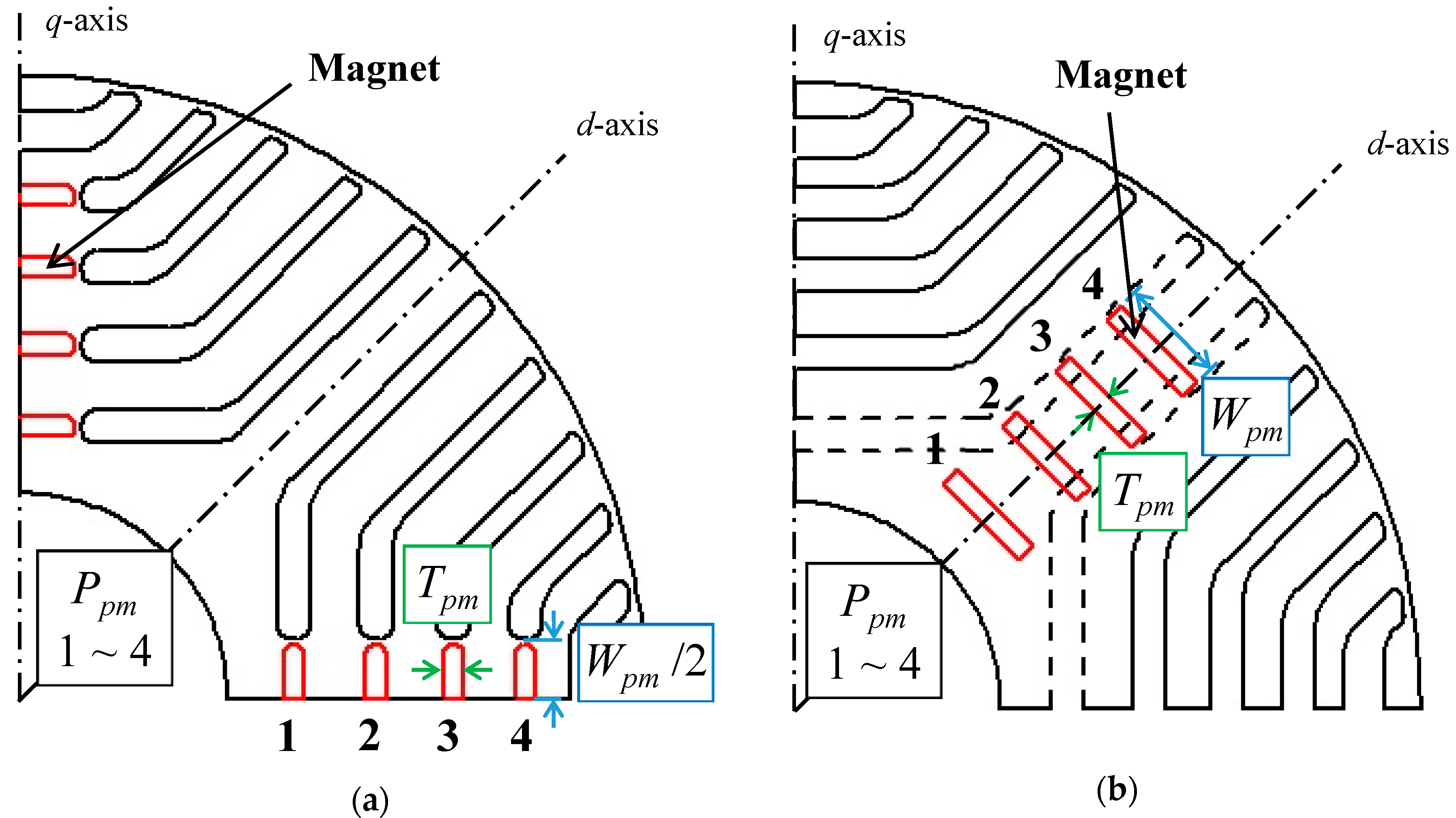
2.2. Configuration of Investigated Motors

As previously illustrated in Figure 1, for the rotor configuration of Type 1, the PMs are embedded along the flux barriers and located in the central part of each rotor pole. As indicated in Figure 1, Ppm is the magnet position from 1 to 4, Wpm is the magnet width and Tpm is the magnet thickness. For the Type 2 configuration, the PMs are arranged along the d-axis. Both types have the same PM positions viewed from the motor shaft (e.g., the PMs at Position 1 of Types 1 and 2 keep the same distance to the shaft). These arrangements of PM positions help to evaluate the effect of the PM directions (i.e., facing d- or q-axis). Note that, the magnetization of the PMs is all in the parallel pattern. The motor specifications and parameters are listed in Table 2, where the analysis at the peak current condition is for the purpose of exploring the capacity of the motors.
The performance of the prototype motor with Type 1 arrangement has been investigated with both the experiments and FEA simulations in Reference [23], where the results show that although the torque is high, this motor could not maintain the power and presented a low CPSR. This reduces its practical usefulness.
According to the previous discussion and the mathematical models described in the first part of this section, it is worthwhile to study the Type 2 motor as a potential alternative. Note that Section 2 mainly provides the mathematical background and briefly introduces the basic topologies of the two types of motor.

3. Comparative Analysis of Influence of PM Position

In this Section, the analyses on the effect of individual PM position on Type 1 and Type 2 motors using finite element analysis (FEA) were conducted. In these analyses, the no-load analysis aims to investigate the contribution of PM at different positions in the rotor to motor flux, and the on-load analysis is used to study the correlation between the PM position and armature excitation. No complete motor models are involved in this Section.

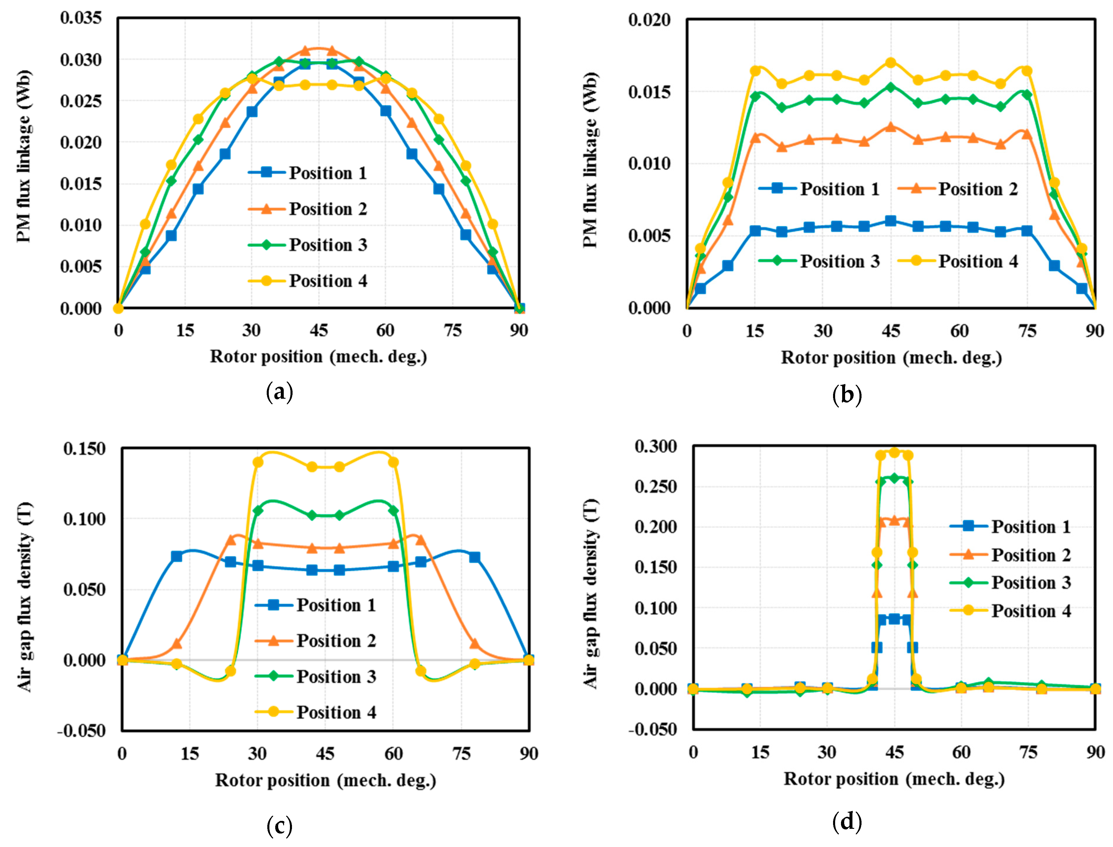
3.1. No-Load Operation Comparison

Base on the prototype motor in Reference [23], the PM pieces with a cross-sectional dimension of 1.5 × 8 mm were chosen and inserted into the PM positions from 1 to 4 (from inmost to outmost) in this study. Note that, all the PMs were fixed inside the flux barriers embracing them. In the beginning, to investigate the influence of the PM position, each time only one PM piece was placed at one of the above positions and the armature current was removed (no-load operation). The PM flux linkage and air-gap flux density Bg for each PM position of both types of motors are illustrated in Figure 5. As can be seen in Figure 5a,c, although the waveforms of the PM flux linkage for Type 1 seem to be different at different PM positions and the trend is unclear, the amplitudes are similar. On the other hand, the waveforms of Bg tend to spread out and the peak value deceases as the PM moves towards the inmost position. As shown in Figure 5b,d, all the PM flux linkage waveforms for Type 2 are basically trapezoidal and the amplitudes increase when the PM moves towards the outmost position. In addition, the waveforms of Bg are the same but the peak Bg increases when the PM moves towards the outmost position. The differences between the two types are significant. The PM position can be used on Type 1 to adjust the waveform of the PM flux linkage and both the waveform and amplitude of the air-gap flux density. For Type 2, this can adjust the amplitude of both the PM flux linkage and air-gap flux density.
The no-load peak flux density in the air gap for each PM position of both types is summarized in Table 3. For Type 1, the flux density at position 1 is the lowest (0.056 T) and that at position 4, is the highest (0.075 T). Similarly, for Type 2, the flux density at position 1 is the lowest (0.025 T) and that at position 4, is the highest (0.083 T). However, the lowest flux density for Type 2 is lower than Type 1, while the highest flux density for Type 2 is higher than Type 1. Thus, the no-load air-gap flux density for the Type 2 rotor seems to be more sensitive to positions. This is possibly because for Type 2, the PM flux is not blocked by the outer flux barriers while the blockage appears for Type 1. The previous analyses imply that for Type 1, the room for the PM flux can be more at the inward positions, i.e., larger or stronger PM [23], while for Type 2, more PM for the outward position could be used. In addition, the improvement of the PM flux linkage and air-gap flux density can be anticipated when the number of PM layers or the PM width increases, which is analyzed later.

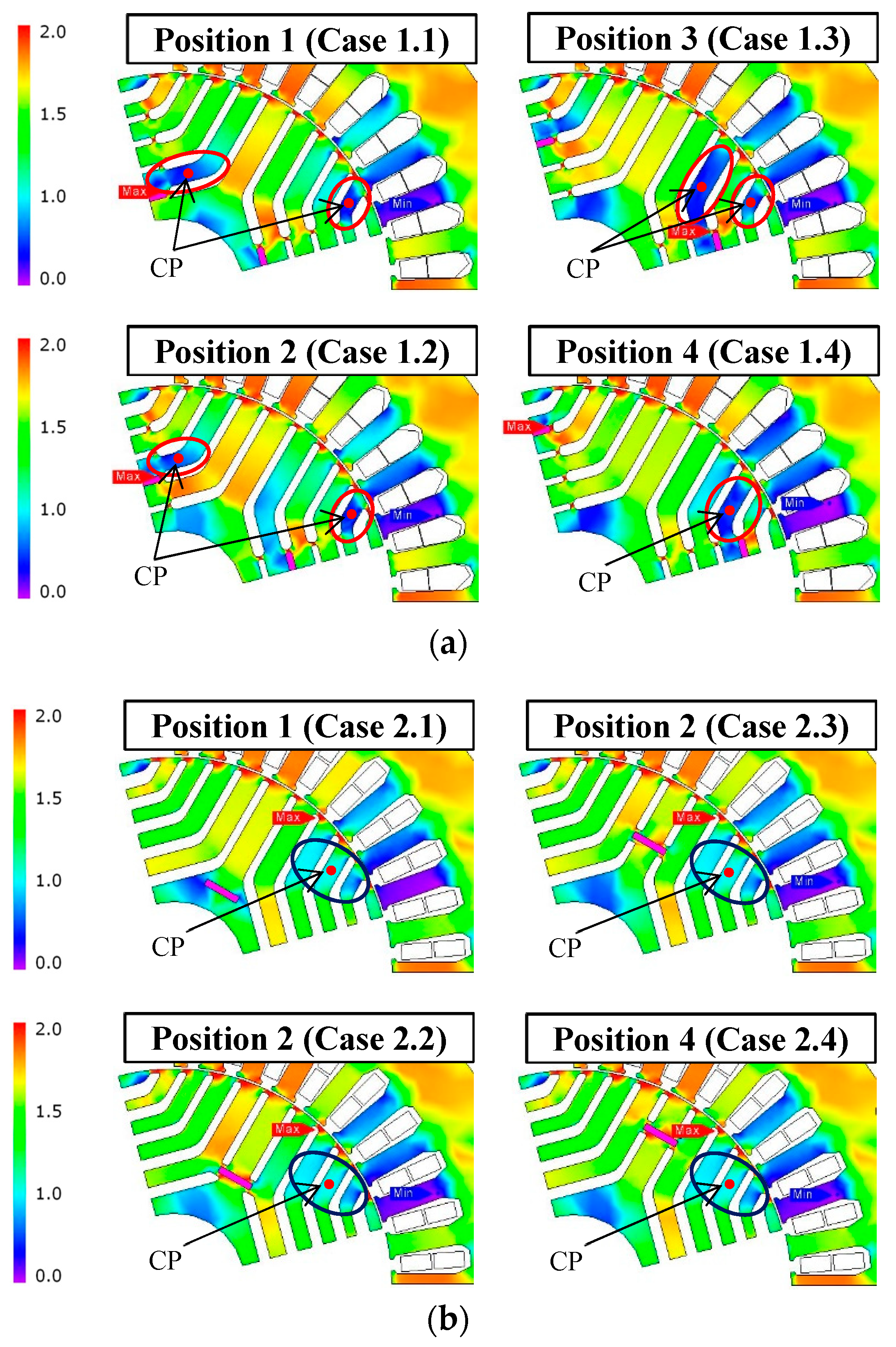
3.2. On-Load Operation Comparison and Flux Balance Index

To fully investigate the influence of PM positions, the on-load operation is considered. Figure 6 shows the flux density distribution in the rotor with an 80 A peak current and maximum torque for each PM position (single PM each case). For Type 1, the most unbalanced flux density distribution occurs at the flux segments near the PMs (red circle) since the PM flux is obstructed by the surrounding flux barriers. The heavily unbalanced flux distribution may cause the PMs not to be utilized efficiently and lead to problems, such as local saturation, torque ripple or risk of demagnetization in motors [36]. For Type 2, the unbalance also occurs but appears to be lighter (dark blue circle) and the condition is almost the same for every PM position. This paper develops an index called the flux balance index to rate the degree of balance of flux distribution, which is given as:
K u = B u B r o t o r · 100 %
where Bu is the lowest flux density at the central point (CP) of the main unbalanced magnetic distribution zones as highlighted in Figure 6, and Brotor is the average flux density in the rotor core obtained from a number of selected points (40 points in this paper) evenly spread out on the rotor core, as illustrated in Figure 7. The selection of these points only aims to represent the average flux density in the rotor without a particular criterion. Note that the determination of Bu and Brotor does not take into account the singularities of the magnetic field, which do not represent the general magnetic distribution although these points are significant for saliency and the torque of motors [18,37]. The higher the flux balance index is, the better and more balanced magnetic distribution is in the rotor. The flux balance indices for various the PM positions of both types of motors are shown in Table 4. As can be seen, for Type 1, the flux balance index increases in the order of PM positions from 1 to 4 [Cases 1.1 to 1.4 in Figure 6a], indicating that the magnetic distribution would be better when the PM moves outward. In contrast, for Type 2, the unbalanced zones and the unbalanced condition do not seem to change as the PM position changes [Case 2.1 to 2.4 in Figure 6b]. This may be due to the fact that for such a configuration, the PM flux is not obstructed by the flux barriers. Furthermore, this unbalance is only caused by the armature reaction at load condition. As a result, Type 2 has a greater flux balance index than Type 1 does, meaning that the arrangement of PMs in Type 2 can be a decent choice to help improve the balance of the magnetic field.
A brief comparison of the torque and torque ripple between the various PM positions of both types is shown in Figure 8. It can be seen that the torque ripple for Type 1 significantly changes with the PM positions, but this does not happen in Type 2. As previously mentioned, for Type 1, both the flux balance index and the locations of unbalance zones vary with the PM position, and the most unbalanced area occurs on the segment near the PM wherever it is placed (Figure 6a and Table 4). For Type 2, in contrast, both the flux balance index and the unbalanced zones seem to be independent of PM position (Figure 6b and Table 4). This indicates that the magnetic distribution in a Type 2 rotor is insensitive to the PM position, and this accounts for the invariant torque ripple with PM positions. In other words, for Type 1, the selection of PM position in a rotor should consider its effect on the magnetic distribution and thus torque ripple. For Type 2 motors, the torque ripple should not be a major concern for the placement of the PM. Note that, the torque output level is not affected significantly by the PM positions and motor types.
To fully compare the contribution of each PM position on torque production, the current is regulated in terms of the magnitude and phase advances with respect to the q-axis. The current Iq is kept at 70A and Id is changed from 10 to 40 A, which considers the cross influence between the d- and q-axes and limits the armature within the peak value, i.e., 80 A. As the result shown in Figure 9, for Type 1, the torque decreases when the PM advances to position 4. In Type 2, although the highest air-gap flux density at position 4 is much higher than position 1, the torque is not much different at any positions. Besides, the highest torque can be generated by the PM at position 1 where the PM is separated from the flux barriers (no intersections), as shown in Figure 1b. However, the width of the PM is limited in this case. In Type 1, the most effective PM position in the torque production is the inward one [23] but it is limited by the possible room given in the rotor, and therefore the configuration with multiple PM layers is suitable for Type 1 to enhance the torque output. In Type 2, with the torque production at each PM position being similar and with the highest air-gap flux density occurring at position 4, this implies that the effective PM configuration is outwards, and the multiple PM layers construction may not be necessary.
In this section, small PM pieces have been used in both Type 1 and 2 motors for the comparison of the influence of PM position. Generally, the placement of these small PM pieces does not significantly change the rotor structure, especially for Type 1. However, the larger PM dimension (e.g., wider) or more pieces (e.g., multiple layers) would be more practical, and thus more variation in rotor configuration may require further assessment.

4. Comparative Analysis of Motor Characteristics

From the previous discussions, the comparison for various numbers of the PM layers as well as various the PM positions is presented. In this section, to fully investigate the performance and characteristics, six models broken down into the two types of motors discussed in Section 2 are created and shown in Figure 10, where Models 1, 2, and 3 are categorized in Type 1 and Models 4, 5, and 6 belong to Type 2. In these models, Models 1 and 4 have the PMs installed at position 1, Models 2 and 5 at position 4, and Models 3 and 6 at all the positions. As the previous analysis, the PMs are all magnetized in the parallel pattern. Note that these models can be treated as proper motors and the effect of various PM layouts (inmost, outmost and multiple layers) on motor inductances and torque production can be investigated through these rotor arrangements. All the models have the same main specifications and the PM thickness/volume. Their PM positions and dimensions are given in Table 5. Note that, the PM thickness is 1.5 mm, which is considered to be manufacturable [23,26].

4.1. Motor Inductances

The inductance variation with the phase angle and magnitude of the current are shown in Figure 11, where the current angle was set to be zero for Figure 11c,d. Note that, these are the motor d- and q-axis inductances (Ldm and Lqm) with the presence of PMs rather than the ones without considering the PM flux, i.e., Ld and Lq (stator inductances) in Equations (3)–(8).
First, as shown in Figure 11a,c, for the Type 1 models (Models 1, 2 and 3), the inductance Ldm is the highest for Model 3 but not much higher than the others. The q-axis inductance Lqm is similar for Models 1, 2 and 3, which indicates that PM position does not significantly influence the electromagnetic characteristics of the motors. Conversely, as shown in Figure 11b,d, for the Type 2 models (Models 4, 5 and 6), the PM position has a great impact on Ldm, with the lowest for Model 5 because of the stronger flux created by the PM that limits the armature flux linkage. The inductance Lqm is similar for Models 4, 5 and 6. The above analysis shows that the PM position would be the most important design key for Type 2 motors.
Second, as the current magnitude increases, the inductance Ldm for the Type 1 models decreases rapidly while Lqm decreases gently, as shown in Figure 11c. However, as shown in Figure 11d, both Ldm and Lqm for Type 2 declines slightly with the current magnitude. This results in a small inductance difference (LdmLqm) variation, especially for Model 5 whose Ldm and Lqm almost do not change. This may be attributed to the flux barriers that slightly brings down Lqm. Meanwhile, Ldm decreases mildly because of the alleviated q-axis magnetic saturation effects [38]. The insignificant inductance variation that may benefit sensorless control shows that fewer PM layers and placing the PM outwards would be more beneficial to the Type 2 motor design.

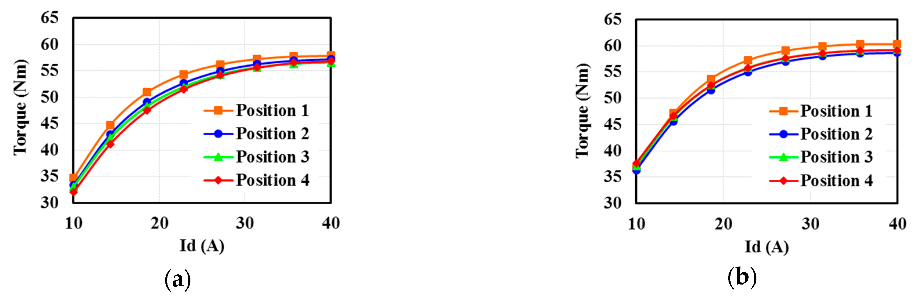
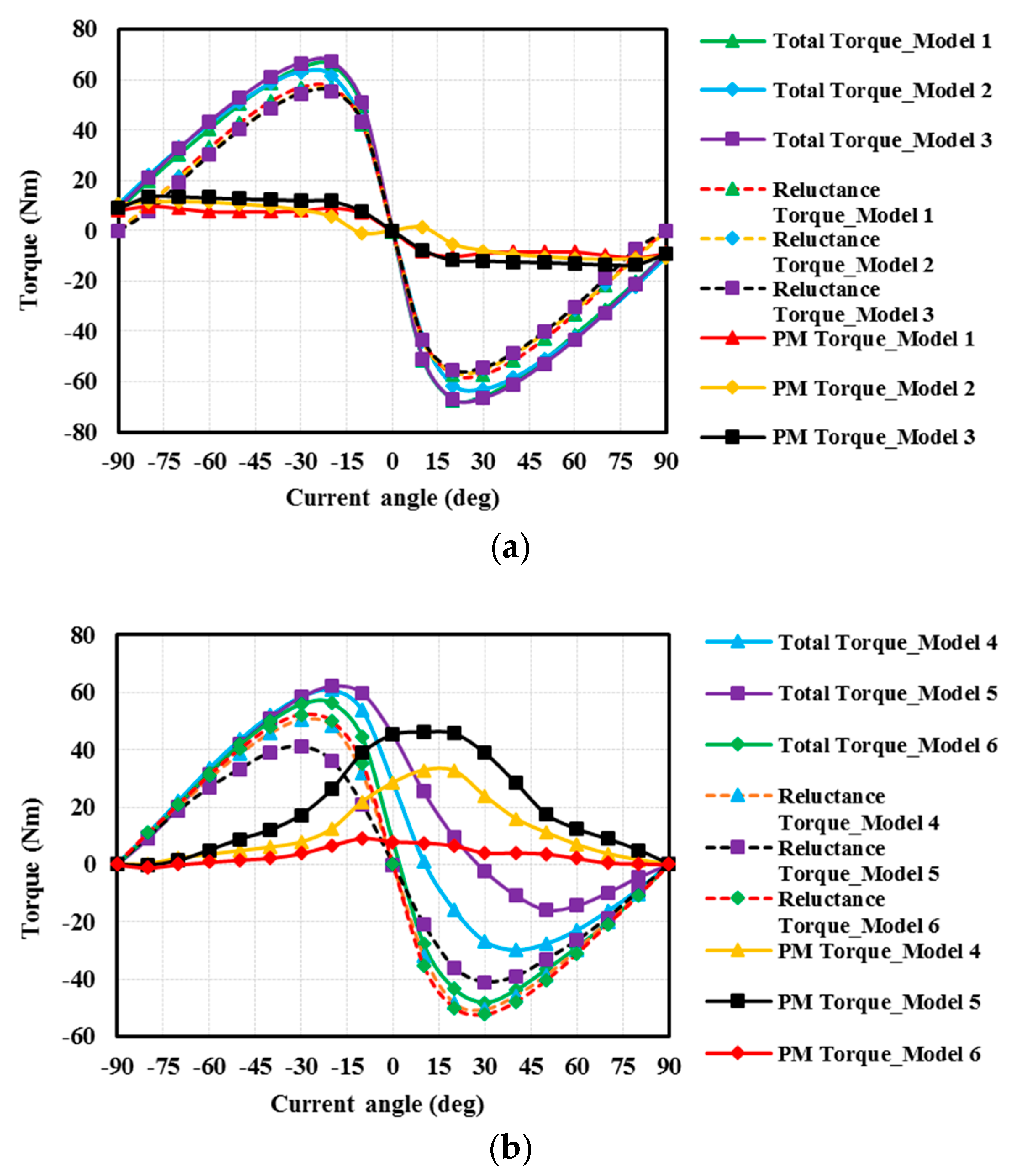
4.2. Torque Production

The torque production and torque components (i.e., PM/reluctance torques) are illustrated in Figure 12 and Table 6. To obtain the curves of torque versus the current angle using FEA, the initial rotor position can first be set up and based on that which the current is applied. Then, the current angle is regulated and swept through the prescribed range so that the output torque can be calculated for each current angle. As shown in Figure 12a, the torque production and torque components for all the models of Type 1 are almost similar. Of these cases, the multiple PM layers one, i.e., Model 3 is the best choice for the sake of its highest achieved total torque and PM torque ratio, as presented in Table 6. However, Model 1 should also be further considered since its torque is only slightly lower, taking the advantage of inmost PM arrangement, as discussed in the previous analysis. As shown in Figure 12b, the torque production and components are diverse for the models of Type 2, which agrees with the previous discussion. The case with the most outward PM and fewer PM layers, i.e. Model 5 would the best choice for its highest achieved total torque by making the most utilization of the PM compared to Models 4 and 6, as presented in Table 6. Furthermore, as presented in Table 6, the torque production of all the models of Type 1 is higher than every model of Type 2. This seems to indicate that the models of Type 1 have better torque production than Type 2. However, the high PM torque and its easy regulation by applying the various PM configurations (i.e., large PM torque difference between these investigated models) is a significant advantage of Type 2. On the other hand, for the Type 1 models, the torque is brought down to zero when the current angle is zero (i.e., Id is zero) while for Type 2, the torque can only reduce to zero at the high current angle since the PM torque and the reluctance torque offset each other. Therefore, for the Type 2 motors, the armature excitation, i.e., the stator current Is can be easily used to regulate the torque characteristics.

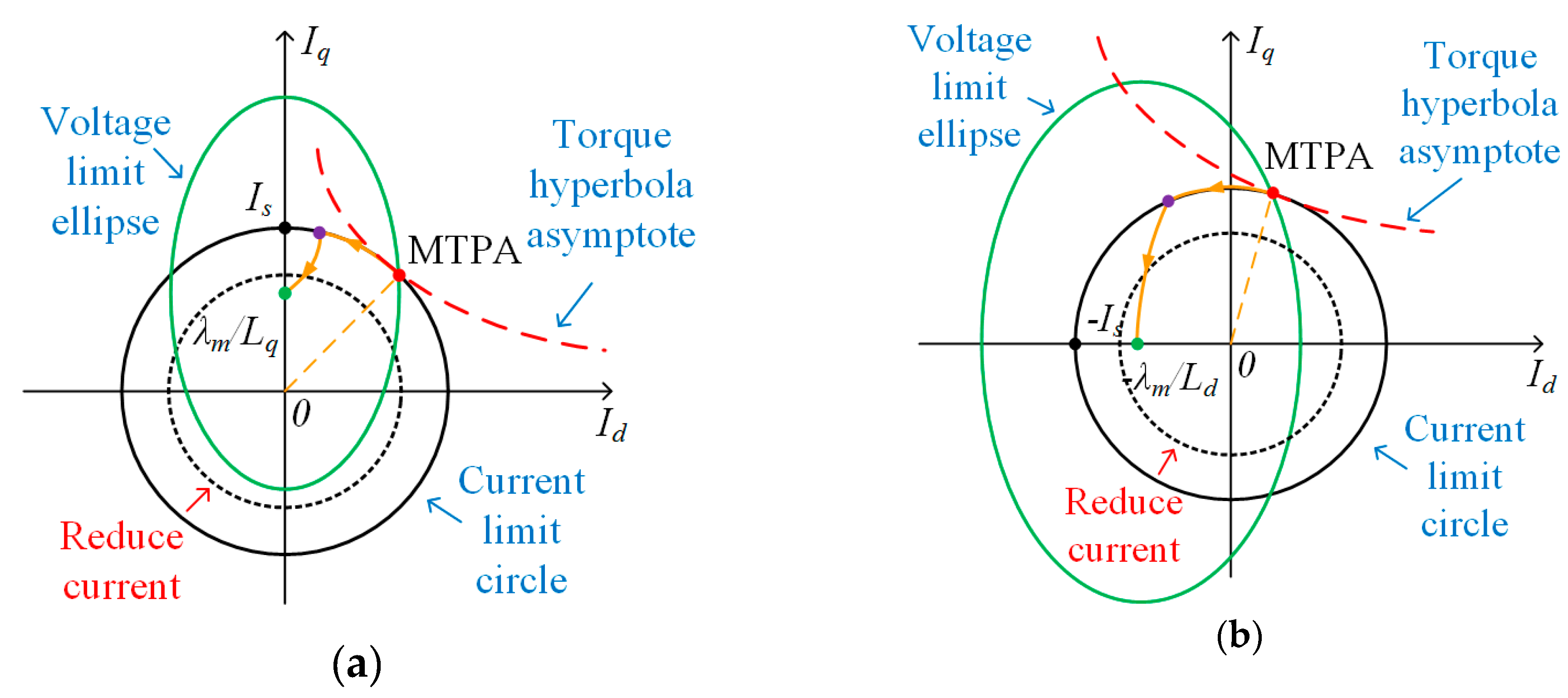
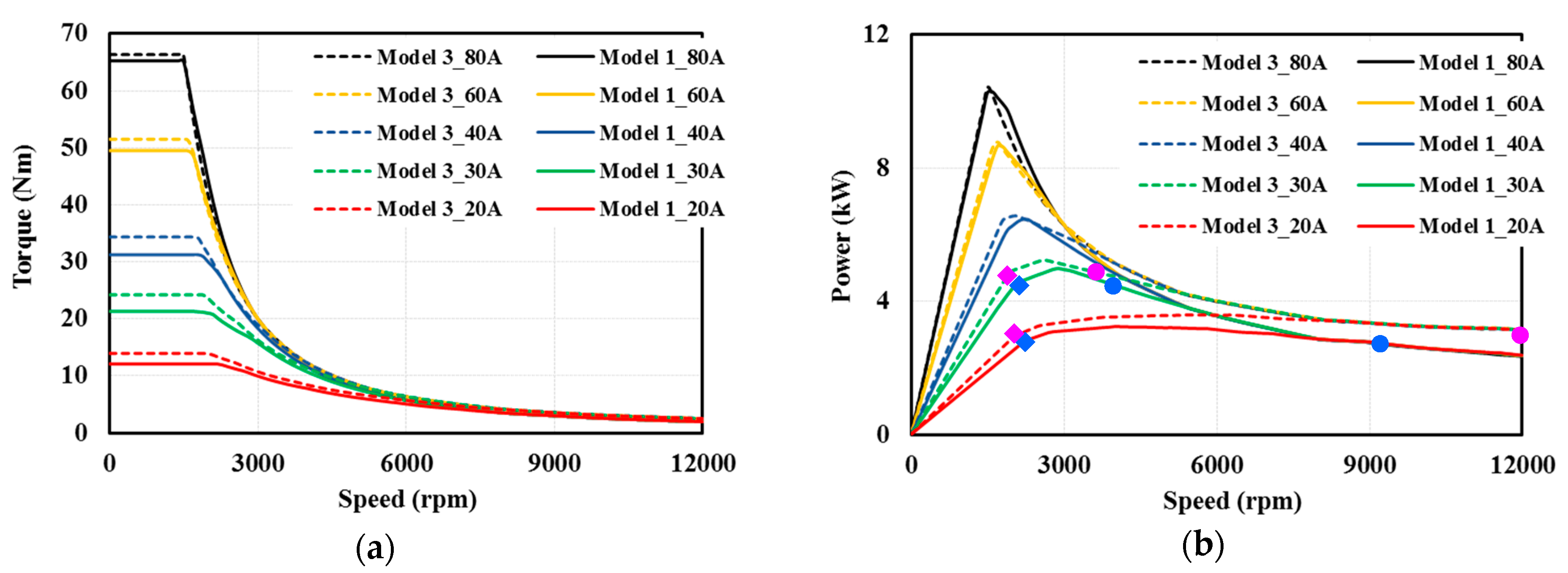
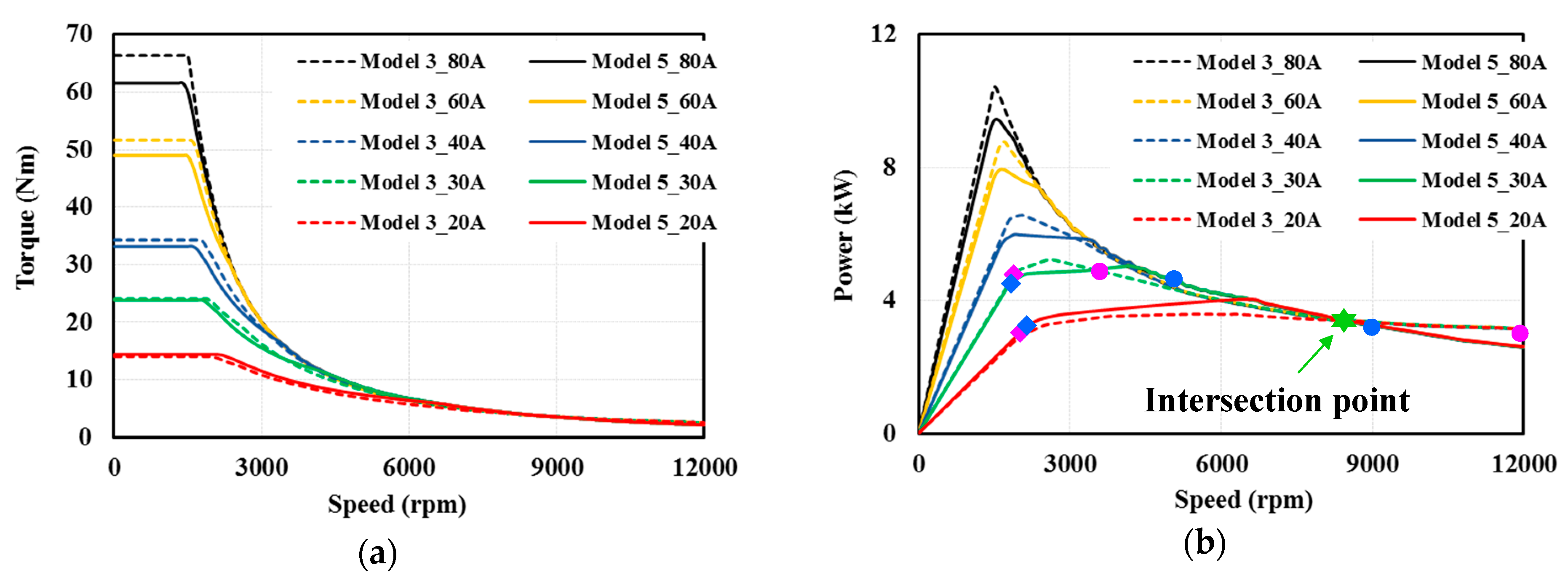
4.3. Torque and Power-Speed Curves

As previously mentioned, the armature current Is can be reduced to be close to Ich to improve the speed range. The relationship between Is and Ich as Is of Models 1, 3 and 5 varies and is presented in Table 7, where as expected, the Is/Ich ratio generally decreases as Is decreases. Furthermore, Figure 13 and Figure 14 show the comparison of torque-speed and power-speed curves between Models 1, 3 and 5, where a 220 V DC voltage is applied. In these curves, the rhombuses and circles denote the start- and end-points of the constant power region. The pink ones are for Model 3 and the blue ones are for Models 1 or 5. As can be seen in Figure 13 and Figure 14, for the three models, the power-speed curves tend to converge at high speed and are partially overlapping. When Is reduces to be close to Ich, the CPSR of the motors improves but the torque and the power suffer some reduction. In Figure 13, the torque and power-speed curves of Model 1 are constantly slightly lower than Model 3 for the same Is although the highest torque production is obtained when the PM is at the inmost position in the rotor. In contrast, although at a low speed operation, the torque production of Model 5 is lower than Model 3, but the difference decreases as Is decreases. This results in an enhancement of the power-speed curves and CPSR for Model 5, which then surpasses Model 3, as seen in Figure 14. However, if Is continues to reduce, e.g., Is = 20 A, the CPSR of Model 5 cannot maintain the superiority to that of Model 3. This can be observed via the power-speed curves where there is an intersection point between these curves. The power corresponding to this point is denoted the intersection power, Pi. For such an intersection, if the required output power is greater than Pi, the CPSR of Model 5 is better than Model 3 and vice versa. Note that, as can be seen in Figure 14, this intersection point locates at the overlap of the MTPV control [33] regions of the target models so that this point no longer depends on the required current, but on the electromagnetic properties or the motor construction, i.e., PM flux linkage, inductance and Ich.
From the above discussions, with limited PM volume (less than common IPM motors), the selection of torque and power is closely related to desired motor speed range and needs to be chosen carefully by simultaneously considering the mechanical and electromagnetic characteristics of the motors and their applications. Although these motors are ideally infinite speed [16], the actual operating speed is limited. In addition, the selection of the PM positions and directions, e.g., moving PM from q-axis to d-axis in this paper, is the key to improve the performance of SynRMs with limited PM used.

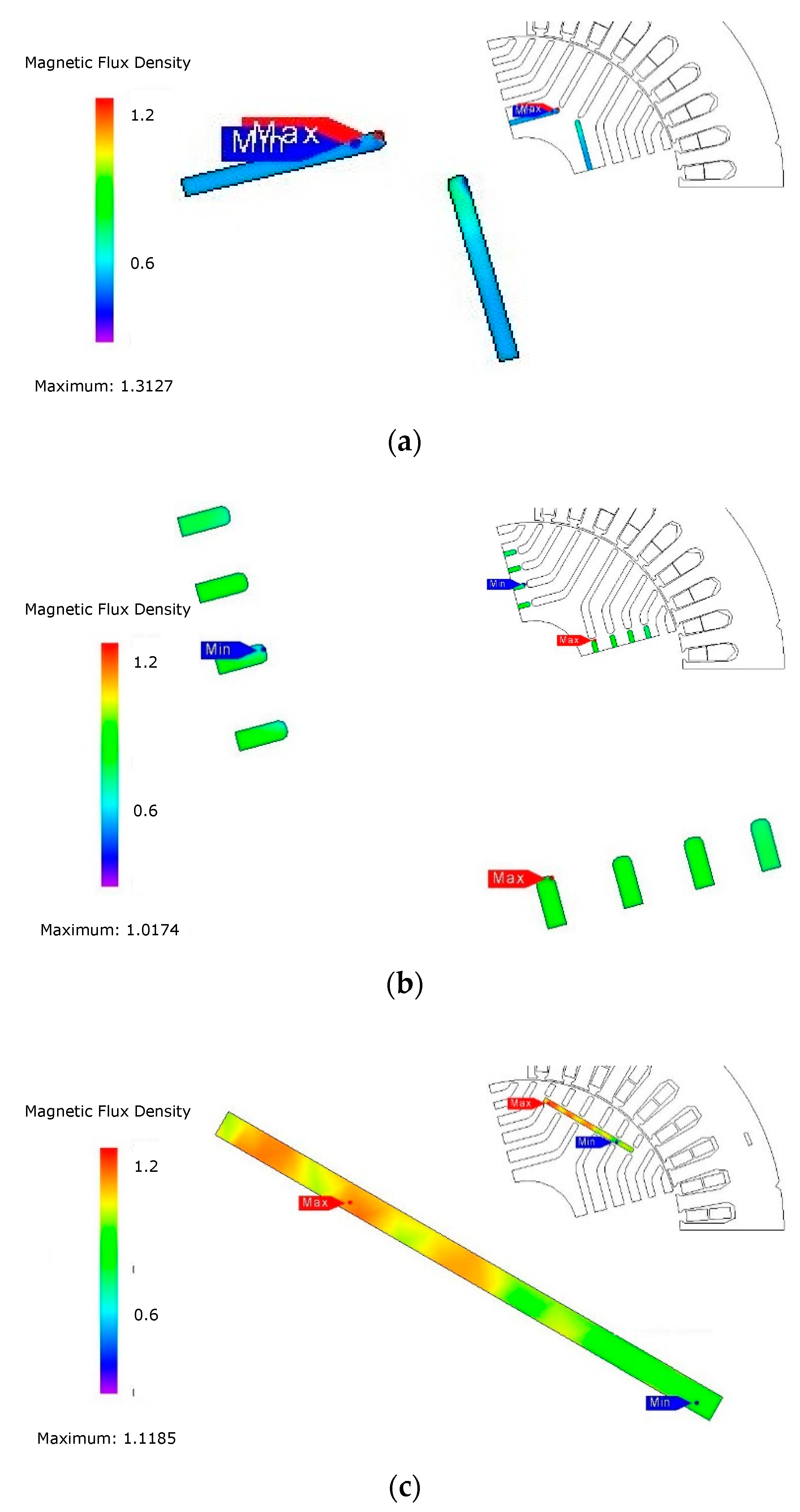
4.4. Demagnetization Analysis

The no-load PM flux linkage and air-gap flux density of Models 1, 3 and 5 are shown in Figure 15. It can be seen that when the PM width increases, the PM flux linkage and air-gap flux density of Type 2 (Model 5) increases significantly. This demonstrates the intensification of the magnetic field that is enabled by placing the PM along the d-axis instead of the q-axis. This can also explain the high PM torque ratio of Model 5 as presented in Table 6.
The distribution of flux density in the PMs of Models 1, 3 and 5 under the peak current at 120 °C are shown in Figure 16. The average flux density in the PMs at various temperatures are presented in Table 8. Note that, the demagnetization curves of N35H (PM material) are illustrated in Figure 17 [16,39]. It can be seen that the flux density in the PMs of Model 1 is very low, meaning that the PMs can be easily demagnetized. Moreover, the flux density in the PM of Model 1 is lower than Model 3 where the PMs are inserted at all positions. This implies that if only the inward PM position is used, an appropriate thickness of the PM should be carefully chosen to avoid irreversible demagnetization. The PMs in Models 3 and 5 have better demagnetization resistance compared to Model 1 since they possess better operating points, as the flux density presented in Table 8. Particularly, Model 5 possesses an advantage with an average PM flux density over 0.8 T. In contrast, the PMs in Model 3 can be locally demagnetized since their flux density are low, as shown in Figure 16. The key is the direction of the flux. In Type 1, the q-axis armature flux is opposing the PM flux and then reducing the flux at the q-axis. Instead, in Type 2, the d-axis armature flux and PM flux are in the same direction and then the d-axis flux is intensified. The motors that employ flux intensifying such as the Type 2 ones have been called the flux intensifying IPMSM [38,40,41]. However, in this paper, less PM is used for the rotor with a dominant reluctance torque, and therefore they should still be considered as a kind of SynRMs. They are named the FI-PMa-SynRM in this paper [26].
Overall, as investigated in this section, the layout with the PMs crossing the flux barriers have a decreased possibility to be demagnetized.

5. Discussion

Based on the previous analyses, some brief summaries are listed as follows.
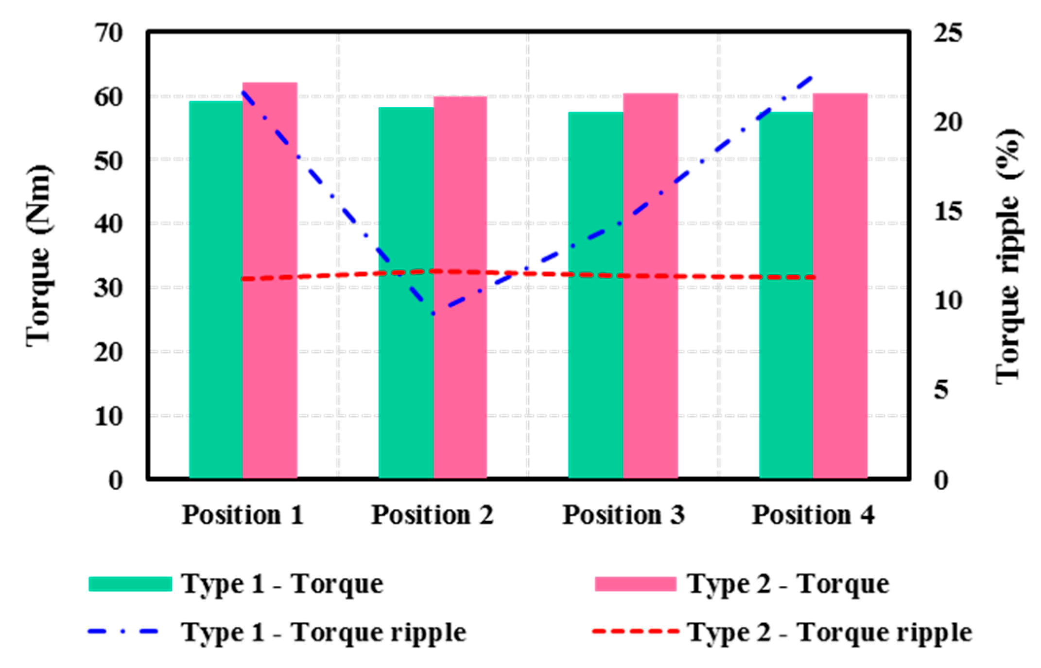
  • For the effect of the PM position, the outward PMs generally produce greater air-gap flux density but torque production does not exactly have the same trend.
  • The PM position and its arrangement in the d- or q-axis have a great impact on flux distribution in the rotor where the d-axis PM arrangement possesses a higher flux balance index.
  • The PM position has a greater impact on motor inductance of the Type 2 motor than the Type 1 one and the effect is approximately linear.
  • Model 3 (conventional multiple-layer PMa-SynRM) has the highest torque production while Model 5 (FI-PMa-SynRM) has the most utilization of PM.
  • Model 5 (FI-PMa-SynRM) is the best choice for demagnetization resistance while Model 1 is the worst one.
  • For SynRM with a limited PM amount, the reduction of armature current Is leads to an increase of CPSR but a trade-off with torque reduction should be considered.
The experimental studies were reported in [23], where the simulations were conducted using the same software package (JMAG). Since the focus of this paper is on the analysis and comparison of several types of SynRM rotors, therefore the experiments are not provided here.

6. Conclusions

In this paper, the analyses for six models of SynRMs with two different categories of PM layouts have been conducted, and their performance and electromagnetic characteristics have been comprehensively compared. From these analyses, it can be observed that the layout with PMs being arranged along the q-axis or embedded into the flux barriers has better torque production capability. For the other layout with the PM facing the d-axis or across the flux barriers, the advantages of SynRMs using a limited PM amount can be maintained and the inherent drawbacks, such as irreversible demagnetization, can be overcome. These indicate that, for SynRMs with a limited amount of PM added and placed along the d-axis would better make use of the PM. In addition, the PM arrangement at the inward position is a decent choice for SynRM with the q-axis PM, but the PM dimension should be calculated carefully to avoid irreversible demagnetization.

Author Contributions

D.-K.N. conceived and conducted the research and wrote the paper. M.-F.H. suggested the research topic, guided D.-K.N. to complete the research and helped edit and finalize the paper. M.-F.H. also provided the laboratory space and facilities for this study.

Funding

This work is supported by the Ministry of Science and Technology, Taiwan under project contracts MOST 108-2622-8-006-014 and 107-2622-E-006-005-CC2.

Acknowledgments

The authors would like to thank Thanh Anh Huynh for his help in this work. JSOL is also acknowledged for providing JMAG software.

Conflicts of Interest

The authors declare no conflicts of interest.

References

  1. Lipo, T. Synchronous reluctance machines—A viable alternative for AC drives. Electr. Mach. Power Syst. 1991, 19, 659–671. [Google Scholar] [CrossRef]
  2. Ozcelik, N.G.; Dogru, U.E.; Imeryuz, M.; Ergene, L.T. Synchronous reluctance motor vs. induction motor at low-power industrial applications: Design and comparison. Energies 2019, 12, 2190. [Google Scholar] [CrossRef]
  3. Ibrahim, M.N.; Sergeant, P.; Rashad, E.M. Synchronous reluctance motor performance based on different electrical steel grades. IEEE Trans. Magn. 2015, 51, 1–4. [Google Scholar] [CrossRef]
  4. Reddy, P.B.; El-Refaie, A.M.; Galioto, S.; Alexander, J.P. Design of synchronous reluctance motor utilizing dual-phase material for traction applications. IEEE Trans. Ind. Appl. 2017, 53, 1948–1957. [Google Scholar] [CrossRef]
  5. Cai, S.; Jin, M.-J.; Hao, H.; Shen, J.-X. Comparative study on synchronous reluctance and PM machines. COMPEL Int. J. Comput. Math. Electr. Electron. Eng. 2016, 35, 607–623. [Google Scholar] [CrossRef]
  6. Guan, Y.; Zhu, Z.Q.; Afinowi, I.A.A.; Mipo, J.C.; Farah, P. Design of synchronous reluctance and permanent magnet synchronous reluctance machines for electric vehicle application. COMPEL Int. J. Comput. Math. Electr. Electron. Eng. 2016, 35, 586–606. [Google Scholar] [CrossRef]
  7. Carraro, E.; Degano, M.; Morandi, M.; Bianchi, N. PM synchronous machine comparison for light electric vehicles. In Proceedings of the IEEE International Electric Vehicle Conference (IEVC), Florence, Italy, 17–19 December 2014; pp. 1–8. [Google Scholar]
  8. Ibrahim, M.N.F.; Rashad, E.; Sergeant, P. Performance comparison of conventional synchronous reluctance machines and PM-assisted types with combined star-delta winding. Energies 2017, 10, 1500. [Google Scholar] [CrossRef]
  9. Bianchi, N.; Fornasiero, E.; Soong, W. Selection of PM flux linkage for maximum low-speed torque rating in a PM-assisted synchronous reluctance machine. IEEE Trans. Ind. Appl. 2015, 51, 3600–3608. [Google Scholar] [CrossRef]
  10. Guglielmi, P.; Boazzo, B.; Armando, E.; Pellegrino, G.; Vagati, A. Permanent magnet minimization in PM-assisted synchronous reluctance motors for wide speed range. IEEE Trans. Ind. Appl. 2013, 49, 31–41. [Google Scholar] [CrossRef]
  11. Bianchi, N.; Mahmoud, H.; Bolognani, S. Fast synthesis of permanent magnet assisted synchronous reluctance motors. IET Electr. Power App. 2016, 10, 312–318. [Google Scholar] [CrossRef]
  12. Niazi, P.; Toliyat, H.A.; Cheong, D.-H.; Kim, J.-C. A low-cost and efficient permanent-magnet-assisted synchronous reluctance motor drive. IEEE Trans. Ind. Appl. 2007, 43, 542–550. [Google Scholar] [CrossRef]
  13. Lee, J.H.; Jang, Y.J.; Hong, J.P. Characteristic analysis of permanent magnet-assisted synchronous reluctance motor for high power application. J. Appl. Phys. 2005, 97, 10Q503. [Google Scholar] [CrossRef]
  14. Huynh, T.A.; Hsieh, M.F. Performance analysis of permanent magnet motors for electric vehicles (EV) traction considering driving cycles. Energies 2018, 11, 1385. [Google Scholar] [CrossRef]
  15. Cai, H.; Guan, B.; Xu, L. Low-Cost ferrite PM-Assisted synchronous reluctance machine for electric vehicles. IEEE Trans. Ind. Electron. 2014, 61, 5741–5748. [Google Scholar] [CrossRef]
  16. Huynh, T.A.; Hsieh, M.-F. Comparative study of PM-assisted SynRM and IPMSM on constant power speed range for EV applications. IEEE Trans. Magn. 2017, 53, 1–6. [Google Scholar] [CrossRef]
  17. Vagati, A. Synchronous Reluctance Electrical Motor Having a Low Torque-Ripple Design. U.S. Patent 5,818,140, 6 October 1998. [Google Scholar]
  18. Ferrari, M.; Bianchi, N.; Fornasiero, E. Rotor saturation impact in synchronous reluctance and PM assisted reluctance motors. In Proceedings of the IEEE Energy Conversion Congress and Exposition (ECCE), Denver, CO, USA, 15–19 September 2014; pp. 1235–1242. [Google Scholar]
  19. Binns, K.J.; Lawrenson, P.J.; Trowbridge, C.W. The Analytical and Numerical Solution of Electric and Magnetic Fields; Wiley: Chichester, UK, 1992. [Google Scholar]
  20. Moghaddam, R.R. Synchronous Reluctance Machine (SYNRM) in Variable Speed Drives (VSD) Applications. Ph.D. Thesis, KTH Royal Institute of Technology, Stockholm, Sweden, 2011. [Google Scholar]
  21. Morimoto, S.; Sanada, M.; Takeda, Y. Performance of PM-Assisted synchronous reluctance motor for high-efficiency and wide constant-power operation. IEEE Trans. Ind. Appl. 2001, 37, 1234–1240. [Google Scholar] [CrossRef]
  22. Imamura, K.; Sanada, M.; Morimoto, S.; Inoue, Y. Improvement of characteristics by flux barrier shape and magnet thickness of IPMSM with Dy-free rare-earth magnet. In Proceedings of the 15th European Conference on Power Electronics and Applications (EPE), Lille, France, 2–6 September 2013; pp. 1–10. [Google Scholar]
  23. Huynh, T.A.; Hsieh, M.-F.; Shih, K.-J.; Kuo, H.-F. An investigation into the effect of PM arrangements on PMa-SynRM performance. IEEE Trans. Ind. Appl. 2018, 54, 5856–5868. [Google Scholar] [CrossRef]
  24. Pellegrino, G.; Vagati, A.; Guglielmi, P. Design tradeoffs between constant power speed range, uncontrolled generator operation, and rated current of IPM motor drives. IEEE Trans. Ind. Appl. 2011, 47, 1995–2003. [Google Scholar] [CrossRef]
  25. Prins, M.H.A.; Kamper, M.J. Design optimisation of field-intensified permanent magnet machine. In Proceedings of the IEEE International Conference on Electrical Machines (ICEM), Berlin, Germany, 2–5 September 2014; pp. 117–123. [Google Scholar]
  26. Ngo, D.-K.; Hsieh, M.-F.; Huynh, T.A. Torque enhancement for a novel flux intensifying PMa-SynRM using surface-inset permanent magnet. IEEE Trans. Magn. 2019, 55, 8106108. [Google Scholar] [CrossRef]
  27. Pillay, P.; Krishnan, R. Modeling of permanent magnet motor drives. IEEE Trans. Ind. Electron. 1988, 35, 537–541. [Google Scholar] [CrossRef]
  28. Morimoto, S.; Takeda, Y.; Hatanaka, K.; Tong, Y.; Hirasa, T. Designand control system of inverter-driven permanent magnet synchronous motors for high torque operation. IEEE Trans. Indus. Appl. 1993, 29, 1150–1155. [Google Scholar] [CrossRef]
  29. Baek, J.; Bonthu, S.S.R.; Choi, S. Design of five-phase permanent magnet assisted synchronous reluctance motor for low output torque ripple applications. IET Electr. Power App. 2016, 10, 339–346. [Google Scholar] [CrossRef]
  30. Lee, J.H.; Kim, J.C.; Hyun, D.S. Effect analysis of magnet on Ld and Lq inductance of permanent magnet assisted synchronous reluctance motor using finite element method. IEEE Trans. Magn. 1999, 35, 1199–1202. [Google Scholar] [CrossRef]
  31. Ngo, D.-K.; Hsieh, M.-F. Analysis of flux intensifying effect on synchronous motors applied to electric scooter. In Proceedings of the IEEE Vehicle Power and Propulsion Conference (IEEE-VPPC), Hanoi, Vietnam, 14–17 October 2019. [Google Scholar]
  32. Jahns, T.M. Flux-weakening regime operation of an interior permanent-magnet synchronous motor drive. IEEE Trans. Ind. Appl. 1987, 23, 681–689. [Google Scholar] [CrossRef]
  33. Soong, W.L.; Miller, T.H.E. Field-weakening performance of brushless synchronous AC motor drives. IEE Proc. Electr. Power Appl. 1994, 141, 331–340. [Google Scholar] [CrossRef]
  34. Jahns, T.M.; Kliman, G.B.; Neumann, T.W. Interior permanent-magnet synchronous motors for adjustable-speed drives. IEEE Trans. Ind. Appl. 1986, 22, 738–747. [Google Scholar] [CrossRef]
  35. Barcaro, M.; Bianchi, N.; Magnussen, F. Permanent-magnet optimization in permanent-magnet-assisted synchronous reluctance motor for a wide constant-power speed range. IEEE Trans. Ind. Electron. 2012, 59, 2495–2502. [Google Scholar] [CrossRef]
  36. Kim, W.-H.; Kim, K.-S.; Kim, S.-J.; Kang, D.-W.; Go, S.-C.; Chun, Y.-D.; Lee, J. Optimal PM design of PMA-SynRM for wide constant-power operation and torque ripple reduction. IEEE Trans. Magn. 2009, 45, 4660–4663. [Google Scholar] [CrossRef]
  37. Ferrari, M.; Bianchi, N.; Doria, A.; Fornasiero, E. Design of synchronous reluctance motor for hybrid electric vehicles. IEEE Trans. Ind. Appl. 2015, 51, 3030–3040. [Google Scholar] [CrossRef]
  38. Zhu, X.; Yang, S.; Du, Y.; Xiang, Z.; Xu, L. Electromagnetic performance analysis and verification of a new flux-intensifying permanent magnet brushless motor with two-layer segmented permanent magnets. IEEE Trans. Magn. 2016, 52, 1–4. [Google Scholar] [CrossRef]
  39. N35H—Arnold Magnetic Technologies. Available online: https://www.arnoldmagnetics.com/wp-content/uploads/2017/11/N35H-151021.pdf (accessed on 23 July 2019).
  40. Zhu, X.; Wu, W.; Yang, S.; Xiang, Z.; Quan, L. Comparative design and analysis of new type of flux-intensifying interior permanent magnet motors with different q-axis rotor flux barriers. IEEE Trans. Energy Convers. 2018, 33, 2260–2269. [Google Scholar] [CrossRef]
  41. Limsuwan, N.; Shibukawa, Y.; Reigosa, D.D.; Lorenz, R.D. Novel design of flux-intensifying interior permanent magnet synchronous machine suitable for self-sensing control at very low speed and power conversion. IEEE Trans. Ind. Appl. 2011, 47, 2004–2012. [Google Scholar] [CrossRef]
Figure 1. Rotor configurations: (a) The first permanent magnet (PM) arrangement (Type 1); (b) The second PM arrangement (Type 2).
Energies 12 03504 g001
Figure 2. Equivalent circuits: (a) Type 1; (b) Type 2.
Energies 12 03504 g002
Figure 3. Phasor diagrams: (a) Type 1; (b) Type 2.
Energies 12 03504 g003
Figure 4. Circle diagrams: (a) Type 1; (b) Type 2.
Energies 12 03504 g004
Figure 5. The PM flux linkage and air-gap flux density at no-load: (a) The PM flux linkage for Type 1; (b) the PM flux linkage for Type 2; (c) the air-gap flux density for Type 1; (d) the air-gap flux density for Type 2.
Energies 12 03504 g005
Figure 6. Comparison of the flux density distribution in rotors: (a) Type 1; (b) Type 2.
Energies 12 03504 g006
Figure 7. The selected points for the rotor average flux density calculation: (a) Type 1; (b) Type 2, where the PM at position 4 is used as representative.
Energies 12 03504 g007
Figure 8. Torque production for each PM position.
Energies 12 03504 g008
Figure 9. Torque production with Id for each PM position. (a) Type 1, (b) Type 2.
Energies 12 03504 g009
Figure 10. Configurations of motor models: (a) Model 1; (b) Model 2; (c) Model 3; (d) Model 4; (e) Model 5; (f) Model 6.
Energies 12 03504 g010
Figure 11. Inductance comparison: (a) Inductance versus current angle for Type 1; (b) Inductance versus current angle for Type 2; (c) Inductance versus current magnitude for Type 1; (d) Inductance versus current magnitude for Type 2.
Energies 12 03504 g011
Figure 12. Torque production and components: (a) Type 1; (b) Type 2.
Energies 12 03504 g012
Figure 13. Field weakening comparison between Models 1 and 3: (a) Torque-speed curves; (b) Power-speed curves.
Energies 12 03504 g013
Figure 14. Field weakening comparison between Models 3 and 5: (a) Torque-speed curves; (b) Power-speed curves.
Energies 12 03504 g014
Figure 15. No-load magnetic characteristic. (a) PM flux linkage, (b) Air-gap flux density.
Energies 12 03504 g015
Figure 16. Flux density in PM at the 120 °C of temperature: (a) Model 1; (b) Model 3; (c) Model 5.
Energies 12 03504 g016
Figure 17. Demagnetization curves of N35H.
Energies 12 03504 g017
Table 1. The reference motor parameters and torque production.
Reference Motor Source[10][11][21][22][23]
Stator diameter (mm)150200125112160
Stack length (mm)105402740120
Motor volume (L)1.8561.2570.3310.3942.413
PM volume (L)0.0660.0770.0130.0090.023
PM-to-Motor volume ratio (%)3.586.133.932.280.95
PM material typeRare earthFerriteFerriteRare earthRare earth
Number of poles44444
Number of flux barriers for each pole43215
Number of PM layers43214
PM size between layersUnequalUnequalUnequal-Equal
Torque (Nm)17.912.471.274.5467.8
Torque density (Nm/L)9.79.93.811.528.1
Table 2. Main specifications/parameters of models.
Parameter/ SpecificationUnitValueParameter/ SpecificationUnitValue
Desired peak powerkW10Stator diametermm160
Number of phases-3Rotor diametermm94
Number of poles-4Air-gapmm0.5
Number of slots-36Stack lengthmm120
DC voltageV220PM meterial- N35H
Maximum currentA80PM volumemm323040
Number of turnsturns6PM/Motor volume ratio%0.95
Table 3. Air-gap flux density for each PM position.
PM Position1st2nd3rd4th
Air-gap flux density for Type 1 (T)0.0560.0600.0670.075
Air-gap flux density for Type 2 (T)0.0250.0590.0740.083
Table 4. The flux balance index of magnetic distribution in rotors.
PM Position1st2nd3rd4th
Lowest flux density for Type 1 (T)0.2620.3020.3550.372
Average flux density in rotor core for Type 1 (T)1.1041.1111.1031.120
Flux balance index, Ku for Type 1 (%)23.7427.1932.1833.23
Lowest flux density for Type 2 (T)0.6630.6400.6450.641
Average flux density in rotor core for Type 2 (T)1.1901.1711.1721.169
Flux balance index, Ku for Type 2 (%)55.7354.6755.0554.82
Table 5. Position and dimension of PMs.
ItemsModel 1Model 2Model 3Model 4Model 5Model 6
PM position141, 2, 3,4141, 2, 3, 4
PM dimenssion1.5 × 32 mm1.5 × 32 mm1.5 × 8 mm1.5 × 32 mm1.5 × 32 mm1.5 × 8 mm
Table 6. Torque production and components.
ItemsModel 1Model 2Model 3Model 4Model 5Model 6
Maximum torque (Nm)66.363.767.860.962.457.3
PM torque at maximum torque (Nm)8.67.411.911.628.55.5
PM torque ratio (%)13.011.617.619.045.79.6
Table 7. The constant power speed range (CPSR) analysis.
Is (A)8060403020
Ich (A) (Model 1)18.917.113.710.29.4
Is/Ich (Model 1)4.233.522.932.952.13
Ich (A) (Model 3)12.010.79.38.67.5
Is/Ich (Model 3)6.675.594.283.502.68
Ich (A) (Model 5)19.717.215.114.213.7
Is/Ich (Model 5)4.063.492.652.121.46
Table 8. Average flux density in PM.
Temperature20 °C90 °C105 °C120 °C130 °C155 °C
Model 10.403 T0.354 T0.342 T0.327 T0.273 T0.133 T
Model 30.711 T0.614 T0.595 T0.577 T0.563 T0.508 T
Model 50.912 T0.869 T0.860 T0.852 T0.845 T0.828 T

