1. Introduction
An insert device involves a specific geometric form equipped into a tube, functioning as a turbulator. Therefore, it is expected that it can increase the flow turbulence, minimize the thickness of the thermal boundary layer, and also improve the heat transfer coefficient of the flow surface. Many researchers have evaluated the adoption of louvered strip inserts numerically and experimentally and measured its impact on the enhancement of heat transfer [
1,
2,
3,
4,
5,
6,
7,
8,
9,
10,
11,
12]. A louvered strip insert is categorized as a turbulator, having a flat, leaf-like shape, mounted on the wire, and made of thin metals. It has been clearly studied that the louvered strip inserts installed in a parallel-flow concentric tube heat exchanger resulted in higher heat transfer performance in comparison to the plain tube or without the insertion. A high recirculation flow can be created by the tube equipped with louvered turbulators, which is disturbing the boundary layer growth, resulting in the higher heat transfer due to the slightening of the boundary layer thickness. Compared to the plain tube, the addition of louvered strip inserts leads to a higher average Nusselt number,
Nu, as well as friction factor,
f. The characteristics of heat transfer and flow resistance of the tubular heat exchanger equipped with louvered strip elements have been studied by Eiamsa-ard et al. [
1]. In their study, the effects of backward and forward arrangements and various inclined angles,
θ, of 15°, 25°, and 30°, have been clarified. Their study showed that the existence of louvered strip devices facilitates a higher heat transfer rate compared to the plain tube. The increase of the inclined angle results in the increase of
Nu accordingly. The louvered strip can produce a powerful turbulence intensity, creating a rapid flow mixing, particularly at larger inclined angles. In addition, Fan et al. [
2] have conducted a comprehensive numerical simulation in a circular tube equipped with louvered strip inserts, including the thermal-hydraulic performance of turbulent airflow. Slant angles and the louvered strip’s pitch were set as the parameters. Their calculation results showed clearly that these parameters strongly influenced the flow resistance and rate of heat transfer. A larger slant angle and smaller pitch of the louvered strips enhanced the heat transfer rate and increased the flow resistance. However, it seems that the influence of slant angles was more significant compared to the insert’s pitch. It is considered that it is because the slant angle is able to generate a relatively high radial flow velocity.
The impacts of a louvered strip insert, which is equipped in a tubular heat exchanger, on the characteristics of both heat transfer and flow resistance with different nanofluids have been clarified by Mohammed et al. [
3]. They set several slant angles and pitches and studied their impacts. Their results proved that the combination of the high slant angle
α = 30° and small pitch
S = 30 mm could enhance the heat transfer performance by about 367%–411% compared to the plain tube. A larger slant angle produced a higher intensity of turbulence resulting in the fast flow mixing. Furthermore, Huisseune et al. [
4] observed the impacts of the delta winglet and louver geometry on the thermal-hydraulic performance of, e.g., a compound heat exchanger. It was clarified that a small fin pitch and large louvered angle led to a strong flow deflection, therefore leading to a significant contribution of the louvers. In addition, Wenbin et al. [
5] experimentally modified and studied the performance of small pipe inserts with several different spacer lengths, arc radii, and slant angles; furthermore, the analyses also included their influences on the heat transfer, flow resistance, and thermal-hydraulic performances. In their study, a small pipe was formed into an S-shape and was installed on a core rode. It was found that tubes fitted with pipe inserts influenced both the heat transfer coefficient and the friction factor. Tabatabaeikia et al. [
6] reviewed the heat transfer augmentation through the adoption of several different types of inserts. It is presented that among the available types of insert, under different arrangements and conditions, the louvered strip insert showed a better performance in backward flow than in forward flow. In addition, in comparison with any other kind of insertion, the adoption of the louvered strip insert clearly enhanced the heat transfer performance, although it also provides a higher friction factor.
Jang and Chen [
7] performed a numerical, three-dimensional analysis for heat transfer in laminar fluid flow inside a heat exchanger having louvered fins for various louver angles. Moreover, Park et al. [
8,
9] conducted experiments adopting a louvered fin heat exchanger in order to reveal the effect of unequal louver pitch and inclination angle on the thermal performance of the repeated frosting/defrosting cycles. Frost blockage was delayed when the unequal louver pitch was employed, compared to the equal louver pitch case. However, these works clarified that both heat transfer rate and pressure drop varied less in the repeated cycling for larger angles. Based on the mechanism of flow and heat transfer, Wei et al. [
10] developed the mathematical model and continued to perform numerically a comprehensive airside, anti-freezing method during winter. Although using three-dimensional turbulent flow numerical simulations, Sadeghianjahromi et al. [
11] developed both heat transfer and flow friction correlations for tubular heat exchangers having the louvered fins. They claimed that the numerical simulation data was exhibited within ± 15% of the wide ranges of their parameters. Zuoqin et al. [
12] provided a similar tendency of thermal performance under different Reynolds numbers,
Re, for louvered fin configurations.
The enhancement mechanisms of fluid flow and heat transfer observed using a computational calculation method is important to be clarified as they are the key factors to further improve the heat exchanger performance. There are several reasons to study related heat transfer enhancement numerically. The computational calculation becomes a proper choice to be used for predicting the performance based on the knowledge of mechanisms acquired through experiments. Most published reports on heat transfer augmentation by louvered strip inserts are experimental studies, which are lacking the evidence to describe the mechanism of both fluid flow and heat transfer. Hence, after studying and publishing the research works in [
13,
14], we were strongly motivated to continue the work to a numerical analysis of the thermal hydraulic performance inside an enhanced tube equipped with a louvered strip insert with various pitches for turbulent single-phase flow. This is the reason that this work is believed to be able to give a novel academic contribution, especially when compared with the currently available and previously published studies.
2. Computational Method
The geometry of the concentric tube, including the use of inner and outer tubes for hot and cold water, respectively, is represented in
Figure 1, referring to [
9]. A computational domain was developed, and the boundary condition was employed in the domain. Regarding the dimension, the inner tube had inside and outside diameters,
di and
do, of 14.3 and 15.8 mm, respectively. On the other hand, the outer tube had inside and outside diameters,
Di and
Do, of 23.4 and 25.4 mm, respectively. The pipe length
L is 2110 mm. The louvered strip is oval, and its dimensions are 10 mm in length, 6 mm in width, and 1 mm in thickness that sticks on the solid pipe with 2 mm of diameter. Louvered strips were arranged backward with variations in pitch (
S) of 40, 50, and 60 mm with a slant angle
α of 25°. The hot fluid had an inlet temperature of 333.15 K with the
Re at inlet velocity of 10,000–17,500. On the other hand, the cold fluid had a temperature inlet of 300.15 K and a constant mass flow rate of 0.1027 kg/s. In addition, the exit side was subjected to the pressure outlet.
In order to observe the thermal-hydraulic characteristics, covering the fluid flow and heat transfer, water was employed as the working fluid, i.e., the hot and cold water flows circulate in inner and outer tube loops, correspondingly. The used fluid properties depend on the temperature.
Table 1 lists the thermo-physical properties of the used hot and cold water [
15], adopted as the inlet values during the computational process.
Re can be calculated by incorporating the thermo-physical properties of the water and inner diameter of the inner tube, which can be defined as:
where
μ,
u, and
ρ are the fluid dynamic viscosity, fluid velocity, and fluid density, respectively. Furthermore, considering the variations of the velocity,
Re was set to 10,000–17,500. Furthermore, the heat transfer characteristic, represented as the
Nu, can be defined as:
where
k and
h are the thermal conductivity and convective heat transfer coefficient of the water, correspondingly. The characteristics of fluid flow were analyzed using the friction factor,
f, that can be calculated as follows:
f was approximated by using the pressure drop (Δ
P) between the tube inlet and outlet.
In addition, three governing equations, including the continuity, momentum, and energy, were also employed for solving the numerical problem [
16]. Each of them can be represented as follows.
Energy equation:
where
p,
cp,
k, and
T are the pressure, fluid specific heat, fluid thermal conductivity, and temperature, correspondingly. Both subscripts of
i and
k show that the direction is toward
i and
k, respectively.
The numerical model was considered to be steady, turbulent, and incompressible. Moreover, the tube walls were considered to be adiabatic, as well as the boundary condition between the fluid and insert. Both natural convection and thermal radiation were negligible and there is no slip at the tube walls. Computation was generated utilizing the commercial software of Ansys Fluent 19 [
17], employing the finite volume method. It was also employed in order to solve Equations (4)–(6), in addition to the adoption of the
k–ε renormalized group turbulence model. Furthermore, the standard pressure solver with the spatial discretization of the second-order upwind scheme was adopted in this numerical work for solving both energy and momentum equations. Moreover, the semi-implicit method for pressure-linked equations (SIMPLE) algorithm was adopted to approximate the pressure–velocity coupling. In order to validate the plain tube and all louvered strip inserts, a tetrahedron-cell mesh configuration was employed. The regeneration of the mesh is represented in
Figure 2, and in addition, the face sizing method in several areas was also adopted for the model.
The grid system was modeled and generated using the tetrahedral, as shown in
Figure 2. In addition, the face sizing was also conducted to clarify that the grid was sufficiently dense and fulfilled the grid independence. The selected generated grid systems included 5,601,970, 5,531,216, 5,512,714, and 626,635 cells, which are utilized to calculate the louvered strip inserts with
S equals 40, 50, and 60 mm and the smooth-tube case, respectively. These good quality grid systems indicate that their solution is grid independent. The quality of grid systems was maintained with a value of skewness of about 0.2.
3. Results and Discussion
In this work, the comparison of the heat transfer and fluid flow characteristics between the smooth tube calculated using the method used in this study and one obtained using the established correlations was initially conducted in order to ensure calculation accuracy. Calculated
Nu was evaluated and compared by using both the Petukhov and the Gnielinski equation [
18,
19], while
f was analyzed using the Blasius equation [
20].
The Petukhov
Nu can be assumed as follow:
for 10
4 <
Re < 5 × 10
6.
On the other hand, the Gnielinski
Nu equation can be represented as follow:
for 1 × 10
3 <
Re < 5 × 10
6.
Moreover, the Blasius correlation is used to determine the
f given by:
for 4 × 10
3 <
Re < 10
5.
The comparison of
Nu and
f of the smooth tube calculated using the method in this study and one calculated with the established correlations are shown in
Figure 3 and
Figure 4, correspondingly. It can be observed that, the difference between the results of this study with the established correlations was very small under all evaluated cases. Hence, it could be concluded that the present calculation shows very reasonable accuracy. In comparison to the established correlations, the results of the calculation are within ±5.98% deviation of the Petukhov correlation and ±5.04% deviation of the Gnelienski correlation for heat transfer (
Nu), as well as ±2.85% deviation of the Blasius correlation for
f. Furthermore, the differences in
Nu and
f were less than 6% and 3%, respectively, as compared to the experiments. Hence, it can be concluded that the numerical method in this present study provides a confident level of certainty.
In order to verify the heat transfer enhancement influenced by the presence of a backward louvered insert, a comparison with the plain tube (without insertion) was conducted, which is also shown in
Figure 5. It can be observed that the heat transfer characteristic, in terms of the
Nu, increased following the increase of
Re for most cases.
Nu was significantly influenced by the temperature distribution of the fluid flowing inside the enhanced tube.
Re, and therefore also the convective heat transfer, improved accordingly. These results are in coherence with previously conducted studies [
13,
14,
15].
Figure 5 also shows that, for backward louvered strip inserts, a pitch
S of 40 mm provided the highest
Nu and was followed by those of 50 and 60 mm. Furthermore, using the backward louvered insert also offered a better result compared to the plain with the corresponding pitch. The presence of a backward louvered insert can increase the fluid turbulent intensity which is near to the tube wall. In addition, the vorticity around the insert lead to high convective heat transfer compared to the backward louvered insert. The
Nu values for the backward louvered insert with the corresponding pitches of 40, 50, and 60 were in a similar range along the increased
Re. Compared to the forward louvered inserts [
14], the present tube designs provided a significant improvement of heat transfer.
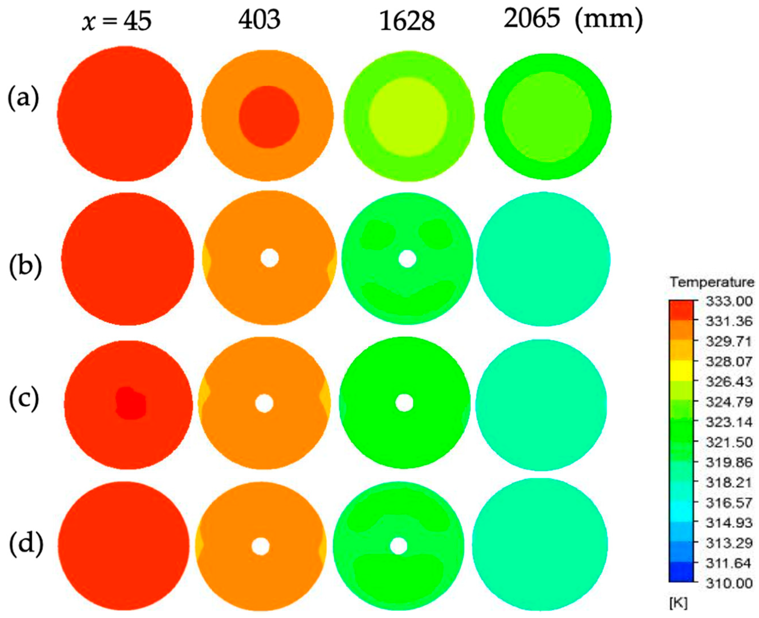
The comparison of the temperature distribution of the enhanced tube with backward louvered insert and plain tube at a
Re of 17,500 for various cross-sections at
x is shown in
Figure 6. It can be observed that for the tube with backward louvered strip inserts, under all evaluated conditions, the temperature distribution seemed more evenly spread. In addition, the temperature distribution became more homogeneously distributed following the increase of the twist pitch. The temperature contours of the backward louvered insert met the same tendency and similar range for the corresponding pitches. In case of the tube having backward louvered insert, a better temperature distribution can be earned, resulting in a better temperature gradient than the one of the smooth tube. An improved temperature distribution causes a larger temperature difference between the tube inlet and outlet, resulting in a better convective heat transfer coefficient. As shown in
Figure 7, for all pitches, the obtained highest temperature gradient and superior temperature distribution are almost similar to the other tube designs, resulting in the best performance for this geometry (see also
Figure 6).
The temperature in each cross-section under
Re of 17,500 is represented in
Figure 7. It is obvious that the temperature distribution of the tubes having a backward louvered strip insert was improved. Therefore, it led to a better temperature gradient compared to the plain tube. A better temperature distribution results in a larger temperature difference between the tube inlet and outlet, as a result improving the convective heat transfer rate. For all the observed pitches, high-temperature gradient and a superior temperature distribution can be achieved, leading to the best performance for this geometry. The pitches
S = 40, 50, and 60 mm resulted in very close values of temperature distribution. It becomes reasonable that the heat transfer rate of all pitch was also close (see again
Figure 5).
Figure 8 shows the streamline patterns for the various designs of backward louvered strip inserts. In the plain tube, the concentration of the streamlines around the wall is shown to be weak owing to the absence of the louvered tape. For all pitches, a uniform distribution of the streamlines can be achieved owing to the generation of the swirl by the louvered tape insert.
Figure 9 shows the difference in the velocity magnitude pathlines among various pitches. Having louvered insert strips produced the fluid flow to become clogged and tended to form certain patterns especially around louvers. Backward louvered strip arrangement provides a vortex effect on fluid flow which can create a better flow mixture in the fluid between the louvered strip and the tube wall. The shortest pitch
S = 40 mm produced the most significant vortices. This vortex effect grows with a decrease in pitch. However, the existence of vortex is not followed by the significant growth of swirl around the strip. This condition caused that the results of the heat transfer rate for all pitches (
S = 40, 50, and 50 mm) were close, although
S = 40 mm provided the highest value (see also
Figure 5 and
Figure 7). The presence of louvered strip inserts can result in swirl and fluid mixing, so that the rate of heat transfer increases.
Figure 10 represents the
f variation with
Re for the plain tube and three different pitches. The value of
f represents the decreasing trend with the rise of
Re. Using a louvered insert also offers a higher frictional factor compared to the plain one. The
f values for the louvered insert with the corresponding pitches of
S = 40, 50, and 60 were about 7.59, 6.51, and 5.77 times as high as the plain tube, correspondingly. Compared to the plain tube, the flow disturbance of backward louvered insert increased the tangential velocity between the secondary flow and the surface along the tube wall. Hence, it can be concluded that the backward louvered insert increases the friction factor significantly in comparison to the plain tube, which is attributed to the blockage and subsequent diminishment of the flow momentum generated by the backward louvered tape as well as the pressure drop for the corresponding backward louvered tape tube design.
Moreover, as represented in
Figure 5 and
Figure 10, the present calculation provides the correlation of the
Nu and
f to
Re, respectively. The tendency is considered consistent with the experimental results from previous works [
13,
14,
15]. It is reasonable that the backward louvered strip inserts can give a higher friction factor compared to the forward design [
14] because the fluid flow is directly blocked by the louvered strip inserts with the backward arrangement.


