Article

Mg6MnO8 as a Magnesium-Ion Battery Material: Defects, Dopants and Mg-Ion Transport

by
Navaratnarajah Kuganathan
1,2,*,
Evangelos I. Gkanas
2 and
Alexander Chroneos
1,2
1
Department of Materials, Imperial College London, London SW7 2AZ, UK
2
Faculty of Engineering, Environment and Computing, Coventry University, Priory Street, Coventry CV1 5FB, UK
*
Author to whom correspondence should be addressed.
Energies 2019, 12(17), 3213; https://doi.org/10.3390/en12173213
Submission received: 8 August 2019 / Revised: 17 August 2019 / Accepted: 19 August 2019 / Published: 21 August 2019

Abstract

:
Rechargeable magnesium ion batteries have recently received considerable attention as an alternative to Li- or Na-ion batteries. Understanding defects and ion transport is a key step in designing high performance electrode materials for Mg-ion batteries. Here we present a classical potential-based atomistic simulation study of defects, dopants and Mg-ion transport in Mg6MnO8. The formation of the Mg–Mn anti-site defect cluster is calculated to be the lowest energy process (1.73 eV/defect). The Mg Frenkel is calculated to be the second most favourable intrinsic defect and its formation energy is 2.84 eV/defect. A three-dimensional long-range Mg-ion migration path with overall activation energy of 0.82 eV is observed, suggesting that the diffusion of Mg-ions in this material is moderate. Substitutional doping of Ga on the Mn site can increase the capacity of this material in the form of Mg interstitials. The most energetically favourable isovalent dopant for Mg is found to be Fe. Interestingly, Si and Ge exhibit exoergic solution enthalpy for doping on the Mn site, requiring experimental verification.

Graphical Abstract

1. Introduction

Rechargeable batteries based on divalent metals such as magnesium, calcium and zinc are being considered as alternatives to Li-ion and Na-ion batteries as they exhibit higher volumetric capacity and redox reactions (more than one electron) [1,2,3]. Among these, Mg-ion battery technology has attracted significant attention due to the high abundance of Mg, the stability of Mg in the atmosphere and the higher melting point of Mg as compared to Li, ensuring that Mg is safer relative to Li [4,5,6,7].
Development of novel cathode materials for Mg-ion batteries is a key challenge as the diffusivity of Mg2+ ions is slower in solid state cathode materials due to the strong ionic interaction of Mg2+ ions with surrounding anions. The low diffusivity results in poor reversible capacity, high voltage hysteresis and low power output. Owing to the difficulty of Mg2+ intercalation, a limited number of electrode materials such as MgMSiO4 (M = Fe, Co and Mn) [8,9,10], MgxV2O5 [11], MgFePO4F [12], spinel sulphides [13], molybdenum chalcogenides [14,15], MgCo2O4 [16] and “Chevrel” Mg2Mo6O8 [15] have been reported in the literature.
“Defective rock salt phase” Mg6MnO8 has been recently proposed as a potential cathode material for rechargeable Mg-ion batteries, as this material shows a number of advantages including six Mg atoms in a formula unit, low-toxicity, high abundance and ease of preparing the pure phase of this material via solid state reactions [17]. In order to examine the applicability of Mg6MnO8, in Mg-ion batteries, Lee et al. [17] used experimental nuclear magnetic resonance (NMR) spectroscopy together with density functional theory (DFT) calculations to characterise the local structure and study the magnetic property of Mg6MnO8. Though further electrochemical study by this experimental group is under way, there are no other experimental reports available in the literature.
Fundamental understanding of Mg6MnO8 can be useful to optimize the performance of this material. This can be achieved by performing calculations with the aid of well-established atomistic simulations based on the classical pair-wise potentials. The main aim of the present work is to provide valuable information to the experimentalist about defect chemistry and diffusion in Mg6MnO8. In previous studies [18,19,20,21,22,23,24,25,26,27,28,29,30,31,32,33,34,35,36,37], this simulation technique has been successfully applied to a number of ionic solids including battery materials. Here, we examine defects, Mg-ion diffusion paths together with activation energies, and favourable dopants on the Mg and Mn site.

2. Computational Methods

Classical pair-wise potential based calculations were performed to examine the most favourable intrinsic defect, possible long-range Mg-ion migration paths with activation energies, and solution enthalpies of isovalent and aliovalent dopants. The GULP code [38] was used. This code uses long-range and short-range forces between ions. The latter arises from electron–electron repulsion and van der Waals attractive forces. The latter was modelled using the Buckingham potentials (Supplementary Materials Table S1). The Broyden–Fletcher–Goldfarb–Shanno (BFGS) algorithm [39] was used to relax the ion positions together with the lattice parameters. Defect modelling was performed using the Mott–Littleton method [40]. This method has been well described in our previous work [18,19,20,21]. As the current simulation is based on the full ionic charge model with dilute limit, the defect enthalpies are expected to overestimate. However, the trend would be the same.

3. Results

3.1. Crystal Structure of Mg6MnO8

The crystal structure of Mg6MnO8 (lattice parameters a = b = c = 8.3818Å and α = β = γ = 90°) was reported by Taguchi et al. [41]. This structure is considered a defect rock salt phase with F m 3 ¯ m space group symmetry. Both Mg2+ and Mn4+ ions form six bonds with six adjacent O2− ions forming octahedrons (refer to Figure 1). The quality of the classical potentials used in this study (refer to Supplementary Materials Table S1) was validated by performing geometry optimization of bulk Mg6MnO8 under constant pressure and comparing the calculated lattice parameters with the corresponding experimental values. The present simulation accurately reproduced the experimental lattice parameters with an error percentage less than 0.6% (refer to Table 1).

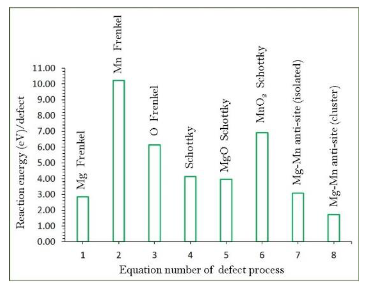
3.2. Intrinsic Defect Processes

Isolated point defect energies (vacancies and interstitials) are useful in calculating Frenkel and Schottky reaction energies in Mg6MnO8. These energetics provide valuable information about the electrochemical behaviour of Mg6MnO8. The following equations (Equations (1)–(8)), written using the Kröger–Vink notation [42], demonstrate the intrinsic defect processes.
Mg   Frenkel :   Mg Mg X     V Mg   +   Mg i
O   Frenkel :   O O X     V O   +   O i
Mn   Frenkel :   V Mn X     V Mn   +   Mn i
Schottky :   6   Mg Mg X   +   Mn Mn X   +   8   O O X     6   V Mg   +   V Mn   +   8   V O   +   Mg 6 MnO 8
MgO   Schottky :   Mg Mg X   +   O O X     V Mg   +   V O   +   MgO
MnO 2   Schottky :   Mn Mn X   +   2   O O X     V Mn   +   2   V O   +   MnO 2
Mg / Mn   antisite   ( isolated ) :   Mg Mg X   +   Mn Mn X     Mg Mn   +   Mn Mg
Mg / Mn   antisite   ( cluster ) :   Mg Mg X   +   Mn Mn X     { Mg Mn :   Mn Mg } X
The calculated reaction energies are reported in Figure 2 (also refer to Supplementary Materials Table S2). Supplementary Materials Table S3 reports the formulas used to calculate the energies of the defect processes. The calculations show that the formation of the anti-site cluster { Mg Mn : Mn Mg } X is the energetically lowest process (1.73 eV/defect). This indicates that the experimental structure consists of both Mg Mn and Mn Mg defects at the same time in the form of a cluster at high temperatures. We considered both defects independently (isolated) and the combined energies. This process (Equation (7)) requires 2.83 eV/defect. The energy difference between the cluster and the isolated form is ‒1.36 eV. This exoergic energy is essentially the binding energy of isolated defects. This further suggests that the isolated defects are not stable and they would combine to form a cluster. In previous experimental and theoretical studies, this type of defect was observed in a variety of materials, including Li-, Na- and Mg-ion battery materials [18,29,30,35,43,44,45,46,47]. The Mg Frankel was calculated to be the second lowest defect energy process (2.84 eV/defect). This process is important for the vacancy-mediated Mg diffusion in Mg6MnO8. This defect is observed at high temperatures as it exhibits endoergic reaction energy. The other Frenkel and Schottky defect processes exhibit high formation energies, suggesting that they cannot be observed at operating temperatures. We considered the loss of MgO in this material by calculating the MgO Schottky process (Equation (5)). In this process, V Mg and V O defects are formed in the lattice. The reaction energy for this process is 3.96 eV per defect, meaning that the loss of MgO is difficult at operating temperatures.

3.3. Mg-Ion Diffusion

The mobility of Mg-ions with low activation energies makes battery materials promising. Determination of Mg-ion paths by experiment is often difficult. The current simulation can provide useful information about migration paths and their activation energies. In a previous work, we used this methodology to identify diffusion paths and activation energies for a variety of Li- and Na-ion battery materials [18,19,20,21,22,23,24,25,26,27,28,29,30,31,32,33,34,35,36,37]. Using classical potential simulation, the Li-ion migration path and activation energy were calculated in LiFePO4 by Fisher et al. [48]. The calculated one-dimensional path along the [010] direction was later observed precisely in the neutron diffraction experiment [49].
In Mg6MnO8, two Mg–Mg local hops were identified. The first Mg–Mg hop (A) has a distance of 2.98 Å and its corresponding activation energy is 0.82 eV (refer to Figure 3). In the second hop (B), Mg diffuses with a jump distance of 5.96 Å and activation energy of 3.72 eV. Table 2 reports the Mg–Mg separations and their activation energies. Figure 4 shows the energy profile diagrams for local hops A and B. These two local hops were connected to construct three-dimensional migration paths. Three different long range paths were identified (refer to Table 3). In the first long range path (A→A→A→A), Mg-ion diffuses in three-dimensional direction (refer to Figure 3). Its overall activation energy is 0.82 eV. This indicates that Mg-ion diffusion in Mg6MnO8 is moderately fast. In the second path (B→B→B→B), Mg-ion migrates along the ac plane. The overall activation energy is 3.72 eV meaning that Mg-ion diffusion along this path is unlikely to occur. The third three-dimensional path (A→B→B→A) consists of both local hops A and B, and its overall activation energy is 3.72 eV. As mentioned earlier, the strong ionic interaction of Mg2+ ions with adjacent oxygen ions reduces its mobility in the lattice. Several approaches, such as reducing the diffusion distance length of Mg2+ ions by synthesising nanostructure materials and decreasing the charge shielding of Mg2+ ions, have been made to improve the mobility of Mg2+ ions [50,51].

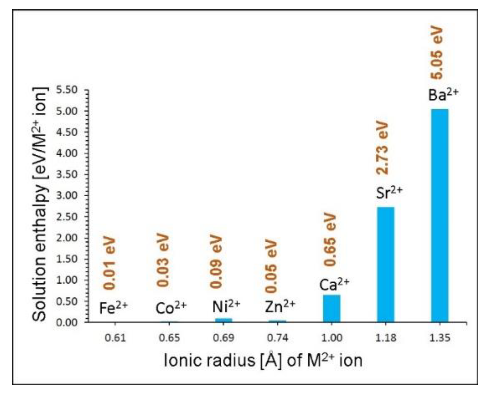
3.4. Dopant Substitution

Substitutional doping on Mg and Mn sites can provide useful information to the experimentalists regarding properties such as capacity and electronic properties. Here we considered a variety of aliovalent and isovalent dopants. Aliovalent substitution needed charge compensation and appropriate defects (interstitials or vacancies) introduced into the reaction equation.
Divalent dopants were first considered on the Mg site. The following reaction equation was used to calculate the solution enthalpy.
MO   +   Mg Mg   X   M Mg   X + MgO
Figure 5 reports the solution enthalpies of MO (M = Fe, Co, Ni, Zn, Ca, Sr and Ba). The lowest solution enthalpy (0.01 eV) was calculated for Fe. Co, Zn and Ni also exhibit favourable solution enthalpies (<0.1 eV), suggesting that they are also promising candidates. This is because the ionic radii of those four dopants are close to each other. The calculations reveal that synthesis of Mg6−xMxMnO8 (M = Fe, Co, Zn and Ni) can be carried out experimentally. Solution enthalpy increases gradually with the ionic radius from Ca2+ to Ba2+. The solution enthalpy for Ca is 0.65 eV, meaning that doping is possible at high temperatures. As both Sr and Ba exhibit high solution enthalpies (>2.70 eV), they are highly unlikely to take place. This is due to the larger ionic radii of Sr2+ and Ba2+ compared to that of Mg2+ (0.72 Å).
Next, we considered a range of trivalent dopants (Al, Ga, Fe, Sc, In, Y, Gd and La) on the Mn site. This would increase the Mg content in this material in the form of interstitials as described in Equation (10). This strategy can increase the capacity of this material providing useful information regarding promising candidate dopants.
M 2 O 3   +   2   Mn Mn X   +   MgO     2   M Mn   +   Mg i   +   2   MnO 2
We report the calculated solution enthalpies of M2O3 in Figure 6. The most favourable dopant was found to be the Ga3+. The solution enthalpy for this dopant is 3.05 eV, suggesting that this process takes place under high temperatures. The possible composition would be Mg6+xMn1-xMxO8 (x = 0.0–1.0). The actual composition should be determined experimentally. The Fe3+ is the second most stable dopant. Solution enthalpy increases with ionic radius of the dopants from Ga3+ to La3+ due to the larger ionic radii of those dopants compared to that of Mn4+ (0.52 Å).
Finally, tetravalent dopants (Si4+, Ge4+, Ti4+, Sn4+, Zr4+ and Ce4+) were considered on the Mn site. The solution energy was calculated using the following reaction equation.
MO 2 + Mn Mn X     M Mn x +   MnO 2
Both Si4+ and Ge4+ exhibit exothermic solution enthalpies (refer to Figure 7), suggesting that they are promising dopants. This is because the ionic radius of Mn4+ is closer to the ionic radii of Si4+ and Ge4+. Experimental verification is needed for the preparation of Mg6Mn1-xMxO8. In our previous study [31], we showed that these two dopants could be exothermically substituted on the Mn site in Li2MnO3. All other dopants exhibit endoergic solution enthalpies. Solution enthalpy increases with ionic radius from Si4+ to Ce4+. The solution enthalpy for Ti4+ is 1.19 eV. This indicates that doping is only possible at high temperatures. The least favourable dopant is Ce4+. As its solution enthalpy is 7.27 eV, it is extremely difficult to carry out doping under normal conditions.

4. Conclusions

Classical pair potential simulation at the atomic scale was used to provide a detailed understanding of key issues related to defects, dopants and Mg-ion diffusion in Mg6MnO8. We identified that the key defect present in this material is the Mg–Mn anti-site. The second most thermodynamically dominant defect is the Mg Frenkel and this defect is present at high temperatures. The Mg-ion diffusion in this material is three-dimensional and moderate. The Ga3+ was identified as a promising dopant on the Mn site to increase the Mg content. Substitutional doping by the Fe2+ on the Mg site is favourable. Exoergic solution enthalpy was calculated for the substitution of Si4+ and Ge4+ on the Mn site, suggesting that both dopants are competitive and experimental investigation of synthesizing the composites Mg6SixMn1-xO8, and Mg6GexMn1−xO8 (x = 0.0–1.0) is of worth.

Supplementary Materials

The following are available online at https://www.mdpi.com/1996-1073/12/17/3213/s1, Table S1: Interatomic potential parameters used in the atomistic simulations of Mg6MnO8. Table S2: Energetics of intrinsic defect process in Mg6MnO8: Table S3. Calculation formulas for intrinsic and extrinsic defect processes.

Author Contributions

Computation N.K.; Writing, N.K. & A.C.; Analysis N.K., A.C. & E.G.

Funding

This research was financially supported by European Union’s H2020 Programme under Grant Agreement no 824072–HARVESTORE.

Acknowledgments

We acknowledge Coventry University and Imperial College London for providing computing facilities.

Conflicts of Interest

The authors declare no conflict of interest.

References

  1. Xu, C.; Li, B.; Du, H.; Kang, F. Energetic Zinc Ion Chemistry: The Rechargeable Zinc Ion Battery. Angew. Chem. Int. Ed. 2012, 51, 933–935. [Google Scholar] [CrossRef]
  2. Muldoon, J.; Bucur, C.B.; Gregory, T. Quest for Nonaqueous Multivalent Secondary Batteries: Magnesium and Beyond. Chem. Rev. 2014, 114, 11683–11720. [Google Scholar] [CrossRef]
  3. Ponrouch, A.; Frontera, C.; Bardé, F.; Palacín, M.R. Towards a calcium-based rechargeable battery. Nat. Mater. 2015, 15, 169. [Google Scholar] [CrossRef] [PubMed]
  4. Novák, P.; Imhof, R.; Haas, O. Magnesium insertion electrodes for rechargeable nonaqueous batteries—A competitive alternative to lithium? Electrochim. Acta 1999, 45, 351–367. [Google Scholar] [CrossRef]
  5. Aurbach, D.; Gofer, Y.; Lu, Z.; Schechter, A.; Chusid, O.; Gizbar, H.; Cohen, Y.; Ashkenazi, V.; Moshkovich, M.; Turgeman, R.; et al. A short review on the comparison between Li battery systems and rechargeable magnesium battery technology. J. Power Sources 2001, 97–98, 28–32. [Google Scholar] [CrossRef]
  6. Huie, M.M.; Bock, D.C.; Takeuchi, E.S.; Marschilok, A.C.; Takeuchi, K.J. Cathode materials for magnesium and magnesium-ion based batteries. Coord. Chem. Rev. 2015, 287, 15–27. [Google Scholar] [CrossRef]
  7. Yoo, H.D.; Shterenberg, I.; Gofer, Y.; Gershinsky, G.; Pour, N.; Aurbach, D. Mg rechargeable batteries: An on-going challenge. Energy Environ. Sci. 2013, 6, 2265–2279. [Google Scholar] [CrossRef]
  8. Feng, Z.; Yang, J.; NuLi, Y.; Wang, J. Sol–gel synthesis of Mg1.03Mn0.97SiO4 and its electrochemical intercalation behavior. J. Power Sources 2008, 184, 604–609. [Google Scholar] [CrossRef]
  9. Orikasa, Y.; Masese, T.; Koyama, Y.; Mori, T.; Hattori, M.; Yamamoto, K.; Okado, T.; Huang, Z.D.; Minato, T.; Tassel, C.; et al. High energy density rechargeable magnesium battery using earth-abundant and non-toxic elements. Sci. Rep. 2014, 4, 5622. [Google Scholar] [CrossRef] [PubMed]
  10. NuLi, Y.; Zheng, Y.; Wang, Y.; Yang, J.; Wang, J. Electrochemical intercalation of Mg2+ in 3D hierarchically porous magnesium cobalt silicate and its application as an advanced cathode material in rechargeable magnesium batteries. J. Mater. Chem. 2011, 21, 12437–12443. [Google Scholar] [CrossRef]
  11. Lee, S.H.; DiLeo, R.A.; Marschilok, A.C.; Takeuchi, K.J.; Takeuchi, E.S. Sol Gel Based Synthesis and Electrochemistry of Magnesium Vanadium Oxide: A Promising Cathode Material for Secondary Magnesium Ion Batteries. ECS Electrochem. Lett. 2014, 3, A87–A90. [Google Scholar] [CrossRef]
  12. Huang, Z.D.; Masese, T.; Orikasa, Y.; Mori, T.; Minato, T.; Tassel, C.; Kobayashi, Y.; Kageyama, H.; Uchimoto, Y. MgFePO4F as a feasible cathode material for magnesium batteries. J. Mater. Chem. A 2014, 2, 11578–11582. [Google Scholar] [CrossRef]
  13. Liu, M.; Jain, A.; Rong, Z.; Qu, X.; Canepa, P.; Malik, R.; Ceder, G.; Persson, K.A. Evaluation of sulfur spinel compounds for multivalent battery cathode applications. Energy Environ. Sci. 2016, 9, 3201–3209. [Google Scholar] [CrossRef] [Green Version]
  14. Wan, L.F.; Perdue, B.R.; Apblett, C.A.; Prendergast, D. Mg Desolvation and Intercalation Mechanism at the Mo6S8 Chevrel Phase Surface. Chem. Mater. 2015, 27, 5932–5940. [Google Scholar] [CrossRef]
  15. Aurbach, D.; Lu, Z.; Schechter, A.; Gofer, Y.; Gizbar, H.; Turgeman, R.; Cohen, Y.; Moshkovich, M.; Levi, E. Prototype systems for rechargeable magnesium batteries. Nature 2000, 407, 724–727. [Google Scholar] [CrossRef]
  16. Gu, S.; Hsieh, C.T.; Huq, M.M.; Hsu, J.P.; Gandomi, Y.A.; Li, J. Preparation of MgCo2O4/graphite composites as cathode materials for magnesium-ion batteries. J. Solid State Electrochem. 2019, 23, 1399–1407. [Google Scholar] [CrossRef]
  17. Lee, J.; Seymour, I.D.; Pell, A.J.; Dutton, S.E.; Grey, C.P. A systematic study of 25Mg NMR in paramagnetic transition metal oxides: Applications to Mg-ion battery materials. Phys. Chem. Chem. Phys. 2017, 19, 613–625. [Google Scholar] [CrossRef]
  18. Armstrong, A.R.; Kuganathan, N.; Islam, M.S.; Bruce, P.G. Structure and Lithium Transport Pathways in Li2FeSiO4 Cathodes for Lithium Batteries. J. Am. Chem. Soc. 2011, 133, 13031–13035. [Google Scholar] [CrossRef]
  19. Kuganathan, N.; Iyngaran, P.; Chroneos, A. Lithium diffusion in Li5FeO4. Sci. Rep. 2018, 8, 5832. [Google Scholar] [CrossRef]
  20. Kuganathan, N.; Ganeshalingam, S.; Chroneos, A. Defects, Dopants and Lithium Mobility in Li9V3(P2O7)3 (PO4)2. Sci. Rep. 2018, 8, 8140. [Google Scholar] [CrossRef]
  21. Kuganathan, N.; Islam, M.S. Li2MnSiO4 Lithium Battery Material: Atomic-Scale Study of Defects, Lithium Mobility, and Trivalent Dopants. Chem. Mater. 2009, 21, 5196–5202. [Google Scholar] [CrossRef]
  22. Fisher, C.A.J.; Kuganathan, N.; Islam, M.S. Defect chemistry and lithium-ion migration in polymorphs of the cathode material Li2MnSiO4. J. Mater. Chem. A 2013, 1, 4207–4214. [Google Scholar] [CrossRef]
  23. Kuganathan, N.; Kordatos, A.; Chroneos, A. Li2SnO3 as a Cathode Material for Lithium-ion Batteries: Defects, Lithium Ion Diffusion and Dopants. Sci. Rep. 2018, 8, 12621. [Google Scholar] [CrossRef] [PubMed]
  24. Kuganathan, N.; Chroneos, A. Defects, Dopants and Sodium Mobility in Na2MnSiO4. Sci. Rep. 2018, 8, 14669. [Google Scholar] [CrossRef] [PubMed]
  25. Kuganathan, N.; Chroneos, A. Defects and dopant properties of Li3V2(PO4)3. Sci. Rep. 2019, 9, 333. [Google Scholar] [CrossRef] [PubMed]
  26. Kuganathan, N.; Kordatos, A.; Chroneos, A. Defect Chemistry and Li-ion Diffusion in Li2RuO3. Sci. Rep. 2019, 9, 550. [Google Scholar] [CrossRef] [PubMed]
  27. Kuganathan, N.; Kordatos, A.; Fitzpatrick, M.E.; Vovk, R.V.; Chroneos, A. Defect process and lithium diffusion in Li2TiO3. Solid State Ion. 2018, 327, 93–98. [Google Scholar] [CrossRef]
  28. Kuganathan, N.; Kordatos, A.; Anurakavan, S.; Iyngaran, P.; Chroneos, A. Li3SbO4 lithium-ion battery material: Defects, lithium ion diffusion and tetravalent dopants. Mater. Chem. Phys. 2019, 225, 34–41. [Google Scholar] [CrossRef]
  29. Kuganathan, N.; Chroneos, A. Na3V(PO4)2 cathode material for Na ion batteries: Defects, dopants and Na diffusion. Solid State Ion. 2019, 336, 75–79. [Google Scholar] [CrossRef]
  30. Kuganathan, N.; Iyngaran, P.; Vovk, R.; Chroneos, A. Defects, dopants and Mg diffusion in MgTiO3. Sci. Rep. 2019, 9, 4394. [Google Scholar] [CrossRef]
  31. Kuganathan, N.; Sgourou, E.N.; Panayiotatos, Y.; Chroneos, A. Defect Process, Dopant Behaviour and Li Ion Mobility in the Li2MnO3 Cathode Material. Energies 2019, 12, 1329. [Google Scholar] [CrossRef]
  32. Kordatos, A.; Kuganathan, N.; Kelaidis, N.; Iyngaran, P.; Chroneos, A. Defects and lithium migration in Li2CuO2. Sci. Rep. 2018, 8, 6754. [Google Scholar] [CrossRef] [PubMed]
  33. Kuganathan, N.; Kordatos, A.; Kelaidis, N.; Chroneos, A. Defects, Lithium Mobility and Tetravalent Dopants in the Li3NbO4 Cathode Material. Sci. Rep. 2019, 9, 2192. [Google Scholar] [CrossRef] [PubMed]
  34. Kuganathan, N.; Tsoukalas, L.H.; Chroneos, A. Defects, dopants and Li-ion diffusion in Li2SiO3. Solid State Ion. 2019, 335, 61–66. [Google Scholar] [CrossRef]
  35. Kuganathan, N.; Chroneos, A. Defect Chemistry and Na-Ion Diffusion in Na3Fe2(PO4)3 Cathode Material. Materials 2019, 12, 1348. [Google Scholar] [CrossRef] [PubMed]
  36. Kuganathan, N.; Dark, J.; Sgourou, E.N.; Panayiotatos, Y.; Chroneos, A. Atomistic Simulations of the Defect Chemistry and Self-Diffusion of Li-ion in LiAlO2. Energies 2019, 12, 2895. [Google Scholar] [CrossRef]
  37. Kaushalya, R.; Iyngaran, P.; Kuganathan, N.; Chroneos, A. Defect, Diffusion and Dopant Properties of NaNiO2: Atomistic Simulation Study. Energies 2019, 12, 3094. [Google Scholar] [CrossRef]
  38. Gale, J.D.; Rohl, A.L. The General Utility Lattice Program (GULP). Mol. Simul. 2003, 29, 291–341. [Google Scholar] [CrossRef]
  39. Gale, J.D. GULP: A computer program for the symmetry-adapted simulation of solids. J. Chem. Soc. Faraday Trans. 1997, 93, 629–637. [Google Scholar] [CrossRef]
  40. Mott, N.F.; Littleton, M.J. Conduction in polar crystals. I. Electrolytic conduction in solid salts. Trans. Faraday Soc. 1938, 34, 485–499. [Google Scholar] [CrossRef]
  41. Taguchi, H.; Ohta, A.; Nagao, M.; Kido, H.; Ando, H.; Tabata, K. Crystal Structure and Magnetic Properties of (Mg6−xLix)MnO8. J. Solid State Chem. 1996, 124, 220–223. [Google Scholar] [CrossRef]
  42. Kröger, F.A.; Vink, H.J. Relations between the Concentrations of Imperfections in Crystalline Solids. In Solid State Physics; Seitz, F., Turnbull, D., Eds.; Academic Press: Cambridge, MA, USA, 1956; Volume 3, pp. 307–435. [Google Scholar]
  43. Nytén, A.; Kamali, S.; Häggström, L.; Gustafsson, T.; Thomas, J.O. The lithium extraction/insertion mechanism in Li2FeSiO4. J. Mater. Chem. 2006, 16, 2266–2272. [Google Scholar] [CrossRef]
  44. Ensling, D.; Stjerndahl, M.; Nytén, A.; Gustafsson, T.; Thomas, J.O. A comparative XPS surface study of Li2FeSiO4/C cycled with LiTFSI- and LiPF6-based electrolytes. J. Mater. Chem. 2009, 19, 82–88. [Google Scholar] [CrossRef]
  45. Liu, H.; Choe, M.J.; Enrique, R.A.; Orvañanos, B.; Zhou, L.; Liu, T.; Thornton, K.; Grey, C.P. Effects of Antisite Defects on Li Diffusion in LiFePO4 Revealed by Li Isotope Exchange. J. Phys. Chem. C 2017, 121, 12025–12036. [Google Scholar] [CrossRef]
  46. Devaraju, M.K.; Truong, Q.D.; Hyodo, H.; Sasaki, Y.; Honma, I. Synthesis, characterization and observation of antisite defects in LiNiPO4 nanomaterials. Sci. Rep. 2015, 5, 11041. [Google Scholar] [CrossRef]
  47. Politaev, V.V.; Petrenko, A.A.; Nalbandyan, V.B.; Medvedev, B.S.; Shvetsova, E.S. Crystal structure, phase relations and electrochemical properties of monoclinic Li2MnSiO4. J. Solid State Chem. 2007, 180, 1045–1050. [Google Scholar] [CrossRef]
  48. Fisher, C.A.J.; Hart Prieto, V.M.; Islam, M.S. Lithium Battery Materials LiMPO4 (M = Mn, Fe, Co, and Ni): Insights into Defect Association, Transport Mechanisms, and Doping Behavior. Chem. Mater. 2008, 20, 5907–5915. [Google Scholar] [CrossRef]
  49. Nishimura, S.I.; Kobayashi, G.; Ohoyama, K.; Kanno, R.; Yashima, M.; Yamada, A. Experimental visualization of lithium diffusion in LixFePO4. Nat. Mater. 2008, 7, 707. [Google Scholar] [CrossRef]
  50. Peng, B.; Liang, J.; Tao, Z.; Chen, J. Magnesium nanostructures for energy storage and conversion. J. Mater. Chem. 2009, 19, 2877–2883. [Google Scholar] [CrossRef]
  51. Novák, P.; Desilvestro, J. Electrochemical Insertion of Magnesium in Metal Oxides and Sulfides from Aprotic Electrolytes. J. Electrochem. Soc. 1993, 140, 140–144. [Google Scholar] [CrossRef]
Figure 1. Crystallographic structure of Mg6MnO8 (space group F m 3 ¯ m ).
Energies 12 03213 g001
Figure 2. Calculated intrinsic defect energies in Mg6MnO8.
Energies 12 03213 g002
Figure 3. Possible long-range magnesium vacancy migration paths considered.
Energies 12 03213 g003
Figure 4. Energy profile diagrams of Mg vacancy hopping between two adjacent Mg sites in Mg6MnO8 (refer to Figure 3).
Energies 12 03213 g004
Figure 5. Enthalpy of solution of MO, (M = Fe, Co, Ni, Zn, Ca, Sr and Ba) with respect to the M2+ ionic radius in Mg6MnO8.
Energies 12 03213 g005
Figure 6. Enthalpy of solution of M2O3, (M = Al, Ga, Fe, Sc, In, Y, Ga and La) with respect to the M3+ ionic radius in Mg6MnO8.
Energies 12 03213 g006
Figure 7. Enthalpy of solution of MO2, (M = Si, Ge, Ti, Sn, Zr and Ce) with respect to the M4+ ionic radius in Mg6MnO8.
Energies 12 03213 g007
Table 1. Comparison between the experimental and calculated structural parameters of cubic ( F m 3 ¯ m ) Mg6MnO8.
ParameterCalcExpt41|∆| (%)
a = b = c (Å)8.42598.38180.53
α = β = γ (°)90.000090.00000.00
V (Å3)598.21588.861.59
Table 2. Calculated Mg–Mg separations and activation energies for the magnesium ion diffusion between two adjacent Mg sites (refer to Figure 3).
Migration PathMg–Mg Separation/ÅActivation Energy/eV
A2.980.82
B5.963.72
Table 3. Possible long-range Mg-ion diffusion paths and their corresponding overall activation energies.
Long-Range PathOverall Activation Energy/eV
A→A→A→A0.82
B→B→B→B3.72
A→B→B→A3.72

