Review

Three-Dimensional Inverse Design Method for Hydraulic Machinery

1
Water Conservancy and Civil Engineering College, China Agricultural University, Beijing 100083, China
2
Beijing Engineering Research Center of Safety and Energy Saving Technology for Water Supply Network System, Beijing 100083, China
*
Author to whom correspondence should be addressed.
Energies 2019, 12(17), 3210; https://doi.org/10.3390/en12173210
Submission received: 19 July 2019 / Revised: 13 August 2019 / Accepted: 17 August 2019 / Published: 21 August 2019

Abstract

:
Hydraulic machinery with high performance is of great significance for energy saving. Its design is a very challenging job for designers, and the inverse design method is a competitive way to do the job. The three-dimensional inverse design method and its applications to hydraulic machinery are herein reviewed. The flow is calculated based on potential flow theory, and the blade shape is calculated based on flow-tangency condition according to the calculated flow velocity. We also explain flow control theory by suppression of secondary flow and cavitation based on careful tailoring of the blade loading distribution and stacking condition in the inverse design of hydraulic machinery. Suggestions about the main challenge and future prospective of the inverse design method are given.

Graphical Abstract

1. Introduction

Hydraulic machinery such as pumps, turbines, and reversible turbines is one of the most important pieces of mechanical equipment for energy conversion. It plays an important role in both industry and our daily life. With the development of economy and society, hydraulic machinery with higher performance is in need by the population, and it is essential for energy saving to further improve the performance of hydraulic machinery, such as increasing efficiency, expanding operating range, and improving stability performance, which is indeed a challenging task for designers due to its flow complexity and multi-objective performance requirements. The design of hydraulic machinery is an inverse problem for which the geometry is designed to meet the performance requirements (or prescribed flow field parameters). The inverse design method (IDM) of hydraulic machinery mainly consists of two parts: One part is the calculation of the flow field; and the other part is calculating the geometry of the blade. It is an iterative process in which the blade geometry is determined according to the calculated flow field. The hydrodynamic performance approaches the prescribed one during the iterative process, and a design result can be achieved when the process converges. Different from conventional design method, which treats geometrical parameters as design variables, the IDM puts hydrodynamic parameters such as pressure distribution and blade loading as the main design variables, and these have a more direct control over the hydraulic performances.
The reliability of the flow field calculation in inverse design is important for the design result of hydraulic machinery. It is known that the real flow in hydraulic machinery is a fully three-dimensional turbulence flow with rotation and curvature. In the early stages, the IDM was mainly based on two-dimensional inviscid flow calculation, and its application was limited due to strict flow simplifications [1,2]. Then, the IDM developed from two-dimensional to quasi three-dimensional [3,4], based on the S1/S2 surface flow calculation theory established by Wu [5], which improves the design quality significantly. Zangeneh [6,7] and Borges [8] developed a three-dimensional IDM based on potential flow theory. The three-dimensional flow field is calculated in a two-dimensional meridional channel by Fourier expansion of the periodic velocity potential function in a tangential direction. The blade shape is calculated based on the flow-tangency condition at the blade surfaces. The method is efficient and robust and is widely used in different turbomachinery such as pumps [9,10,11,12], turbines [13,14], compressors [15,16,17], diffusers [18,19,20], inducers [21,22], and so on. The flow calculation approach in this three-dimensional IDM is based on potential flow theory without viscosity. However, the viscous effects can be introduced by considering some parameters such as blockage distribution or vorticity terms related to fluid viscosity in an interactive way [23].
With the fast development of computational fluid dynamics (CFD), the full three-dimensional turbulence simulation technique for hydraulic machinery design is gradually maturing. It is an easy choice to combine the three-dimensional turbulence simulation technique with the IDM, since the turbulence simulation technique can make up for the limitations in the flow calculation of the IDM and improve the design quality. However, a fully three-dimensional turbulence flow calculation approach is difficult to be directly introduced in the IDM because of its iterative nature, and both the time cost and calculation stability restrict the ability apply this approach. In modern design, CFD simulation techniques play a crucial part in both the trial and error design process of turbomachinery and its automatic optimization design process [24,25]. In fact, it is used as an indispensable tool for evaluation, optimization of the design outcome, and studying the design know-how.
A three-dimensional IDM based on potential flow theory of hydraulic machinery is reviewed in this paper, and its main challenge and future perspective are discussed. The organization of the remaining paper is as follows: Section 2 describes the basic theory of the IDM as well as flow calculation approaches, blade geometry calculation approaches, and the main input design parameters. The flow control methods, including secondary flow and cavitation suppression by tailoring blade loading distributions and blade stacking condition, along with their applications in different hydraulic machinery, are presented in Section Application of the IDM towards optimization is presented in Section The main challenge and future perspective of the inverse design method are given in Section 5.

2. Description of the Inverse Design Method
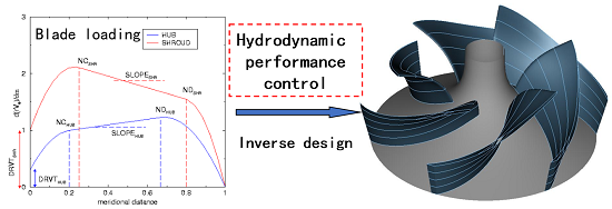
2.1. Basic Idea

There are several kinds of inverse design methods with different flow calculation approaches and different choices of prescribed quantities. Based on different flow calculation approaches, the inverse method can be divided into the inviscid [26,27] or viscous [28,29,30,31,32,33,34,35] category, the compressible [6,31] or incompressible [1,2,3,4,8] category, and the two-dimensional [36,37] or three-dimensional [38,39,40] category. No matter the kind of IDM, the basic idea remains the same. That is, the blade geometry is updated based on the calculated flow in an iterative way. There are mainly two parts in inverse methods: one is the flow calculation, and the other is the blade geometry calculation. The whole process is proceeded in an iterative way, as shown in Figure 1. First, an initial blade geometry and design parameters such as pressure distributions or blade loading distributions are specified. Then, the corresponding flow field of the initial blade geometry is calculated based on inviscid Euler equations or viscous Navier–Stokes equations. After, a new blade geometry is determined based on the calculated flow field by satisfying the flow-tangency condition on the blade surfaces for inviscid flow or by defining the virtual wall motion for the viscous design. Finally, the difference between the initial blade shape and the new one is checked for convergency: If it converges, the process stops, and both the blade geometry and corresponding flow field is obtained; if it does not, one should turn to the flow calculation step again and continue the iterative loop.

2.2. Flow Calculation Based on Potential Theory

A widely used three-dimensional IDM based on potential flow theory for hydraulic machinery is reviewed here. The method was first established by Hawthorne [1,2] for two-dimensional cascade design, then it was extended to three-dimensional cases developed by Zangeneh [6,7] and Borges [8]. In this method, the flow is calculated based on potential flow theory, and the blade geometry is calculated based on the flow tangential condition at the blade surfaces. The basic assumptions of the three-dimensional IDM are that (1) the flow is steady and the incoming flow is uniform and irrotational, (2) the blade has zero thickness and can be represented by a single vortex, (3) the blockage effect is considered by introducing a blockage coefficient, and (4) the flow is incompressible and inviscid.
In the flow calculation of the three-dimensional IDM, the velocity is decomposed to a circumferentially-averaged velocity and a periodic velocity, which are calculated separately. In the rotating frame of the impeller, the relative velocity W can be expressed as
W = V ¯ ω × r + v = W ¯ ( r , z ) + v ( r , θ , z )
where V ¯ and W ¯ are the circumferentially-averaged absolute velocity vector and the circumferentially-averaged relative velocity vector, respectively; v is periodic velocity vector; ω is rotational speed of the impeller; and r, θ, and z are the radial, tangential, and axial coordinates of the cylindrical coordinate system, respectively.

2.2.1. Calculation of Circumferentially-Averaged Velocity

For incompressible steady flow, the continuum equation can be expressed as
V = 0
where V is the absolute velocity vector. Considering the blockage effect of the blade, the circumferentially-averaged absolute velocity V ¯ satisfies the equation
( B f V ¯ ) = 0
where Bf is a blockage coefficient, which is defined as
B f = 1 t θ r B 2 π
where tθ is the tangential thickness of the blade. A stream function φ ( r , z ) can be defined based on Equation (3) to satisfy
V ¯ r = 1 r B f φ z ,   V ¯ z = 1 r B f φ r
where V ¯ r and V ¯ z are the radial and axial components of the circumferentially-averaged absolute velocity, respectively. According to the assumption in Equation (2), the circumferentially-averaged vorticity vector can be expressed as
Ω ¯ = × V ¯ = ( ( r V ¯ θ ) × α )
where Ω ¯ is the circumferentially-averaged vorticity vector, r V ¯ θ is the circumferentially-averaged velocity circulation, and α represents the blade surfaces. The tangential component of the circumferentially-averaged vorticity vector can be expressed as
Ω ¯ θ = V ¯ r z V ¯ z r = e θ Ω ¯
where e θ is the unit vector of the tangential coordinate. Substituting Equations (5) and (6) into Equation (7), we can obtain
r ( 1 r B f ψ r ) + z ( 1 r B f ψ z ) = r V ¯ θ z f r r V ¯ θ r f z
The boundary conditions for Equation (8) are φ = constant at walls and 1 r Ψ s = V ¯ n at both the upstream and downstream boundaries, where s is the distance along the boundaries, n is the unit vector perpendicular to the boundaries, and V ¯ is the circumferentially-averaged velocity vector at the boundaries.

2.2.2. Calculation of Periodic Velocity

Based on the Clebsh expression, the periodic velocity can be decomposed to potential and rotational parts as follows:
v = Φ ( r , θ , z ) S ( α ) r V ¯ θ
where Φ ( r , θ , z ) is the potential function of the periodic velocity, and S ( α ) is a periodic sawtooth function, which can be expressed as
S ( α ) = Re m = e i m B α i m B
where B is the blade number. The periodic velocity also satisfies the continuum equation
v = 0
By substituting Equations (9) and (10) into Equation (11), we can get
2 Φ = S ( α ) 2 r V ¯ θ + ( α r V ¯ θ ) S ( α )
Since the flow has periodic characteristics, the potential function Φ ( r , θ , z ) can be expanded as a Fourier series in the tangential direction:
Φ ( r , θ , z ) = m = Φ m ( r , z ) e i m B θ
Substituting Equation (13) into Equation (12), we can get
2 Φ m r 2 + 1 r Φ m r + 2 Φ m z 2 m 2 B 2 r 2 Φ m = e i m B f ( r , z ) i m B ( 2 r V ¯ θ ) e i m B f ( r , z ) ( f r r V ¯ θ r + f z r V ¯ θ z )
The boundary conditions for Equation (14) are Φ m = 0 at both the upstream and downstream boundaries, and Φ m n = r V ¯ θ n e i m B f ( r , z ) i m B at endwalls.

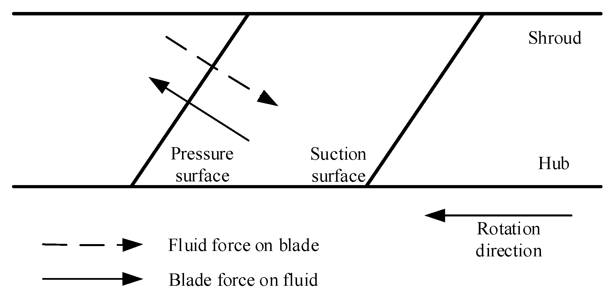
2.3. Blade Geometry Calculation Based on Flow Tangential Condition

Blade geometry is calculated based on the inviscid slip condition at the blade walls with zero velocity component normal to the walls. This flow-tangency condition can be expressed as
W bl α = 0
where α represents the blade surfaces and ∇α denotes a vector perpendicular to the blade surface, and Wbl is the relative velocity vector at blade surfaces. Expanding Equation (15), we can get
( V ¯ z + v z b l ) f z + ( V ¯ r + v r b l ) f r = r V ¯ θ r 2 + v θ b l r ω
where f is the wrap angle of the blade, and V ¯ and v are the circumferentially-averaged velocity and periodic velocity respectively. Equation (16) can be integrated along streamlines in the meridional channel to calculate the blade geometry. Some initial conditions on the wrap angle, called the blade stacking condition, must be prescribed to complete the integration of Equation (16). This blade calculation approach based on inviscid flow-tangency condition is widely used in the inviscid IDM and it can also be applied to viscous flow case by using the transpiration technique [41,42], in which the blade geometry is updated based on the calculated normal and tangential velocity according to mass conversion. Equations (8), (14), and (16) constitute the closed equations of the three-dimensional IDM, and the blade geometry is calculated in an iterate way.

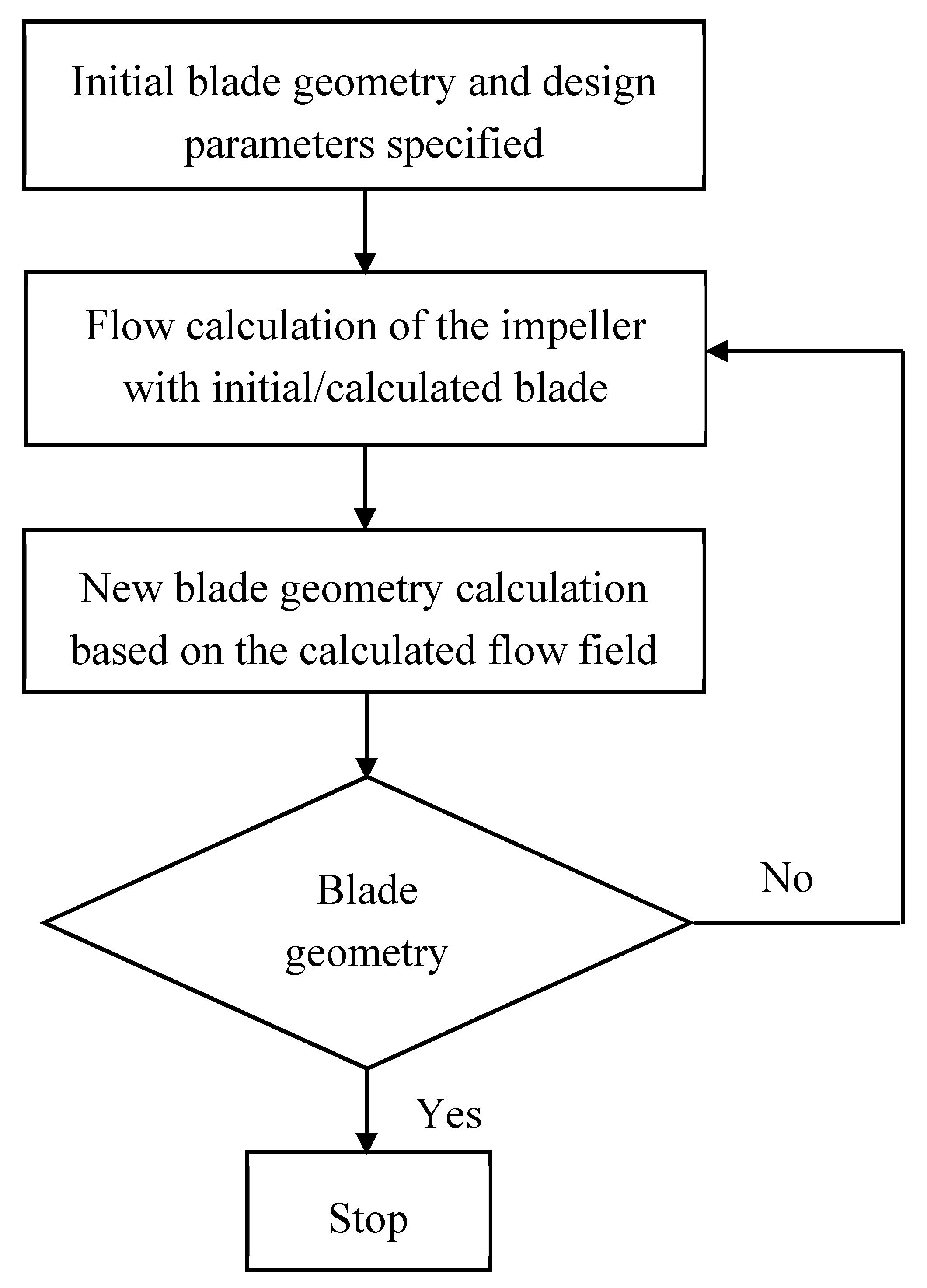
2.4. Convergency of the Inverse Design Method

It should be noted that, in the present IDM, the blade is represented by a series of vortices. Based on this assumption, if the blades are not perpendicular to the endwalls, the vortex sheet, which represents the blade, will result in infinite velocity induced by the vortex system. To avoid this type of velocity singularity, it is necessary to set the normal gradient of both the circumferentially-averaged velocity circulation r V ¯ θ and the wrap angle f to zero at the endwalls. As a result, the boundary condition for the potential function Φ m at the endwalls should be changed to a zero gradient along the normal direction of the endwalls. This condition is an essential one for the convergency of the present IDM.
Another expression of Equation (15) can be written as
f s = V ¯ θ ω r r V s
where Vs is the meridional velocity. It can be seen from Equation (17) that when the radius and meridional velocity is small, which is usually the case along the hub streamline, the denominator on the right side of the Equation (17) is very small, resulting in an unacceptably large value of the wrap angle. In this case, the convergency problem is inevitable; however, it can be solved by carefully setting a V ¯ θ -distribution that closely follows the peripheral speed of the blade. In other words, the specified blade loading distribution should match the meridional channel reasonably to avoid the convergency problem or highly-twisted blade geometry.
The time cost of the IDM depends on both the convergency and the flow calculation approach since it is an iterative process. The convergency of the process depends on the compatibility between the flow calculation part and the blade geometry calculation part in the method. Usually, it is more efficient and robust for the IDM to use inviscid flow calculation approaches, which computes fast and are more compatible with the blade shape calculation based on flow-tangency conditions. For viscous design problems, it usually takes more time since both the flow calculation and blade geometry calculation are more sophisticated, and viscous no slip condition cannot be used directly for blade geometry calculations.

2.5. Main Input Design Parameters

One of the most important input design parameters for the IDM is the blade loading distribution. The pressure distribution has a close relationship with the blade loading distribution. This relationship can be derived based on potential flow theory as
Δ p = p + p = 2 π B ρ W bl r V ¯ θ s
where ∆p is the static pressure difference between the pressure and suction surface of the blade; p+ and p are the pressure at the pressure surface and suction surface, respectively; ρ is fluid density; Wbl is the relative velocity at the blade surface; r is the radial coordinate of a cylindrical coordinate system; V ¯ θ is the circumferentially-averaged tangential velocity; and s is the meridional distance in the meridional channel. In some design methods, the blade loading is defined as ∆p, and in some other ones, the meridional derivative of velocity circulation, namely r V ¯ θ / s in Equation (18), is defined as the blade loading. Hereafter in the present paper, we apply the latter one as the definition of blade loading for uniformity. The blade loading distribution is a key factor for the inverse design, and by tailoring the blade loading distribution, the blade hydrodynamic performance can be controlled in a more direct way than tailoring the geometrical parameters. This is one of the most important advantages of the IDM compared with the conventional design method, which mainly deals with the geometrical parameters.
As aforementioned, an initial value of the wrap angle f should be specified along a spanwise line in the meridional channel between the hub and shroud for the integration of the blade shape based on Equation (16). This initial wrap angle value is called the blade stacking condition. If the wrap angle values are set to be the same along a spanwise line, then a straight blade filament with zero blade lean angle on that line is obtained. By prescribing different values of the warp angle at the shroud and hub, a linear or nonlinear blade filament on the line can be obtained. By doing this, different blade lean patterns can be controlled at certain locations of the meridional streamlines.
The blade thickness distribution is another parameter that needs to be prescribed for the IDM. In the present paper, we focus on the blade loading distribution and the blade stacking condition since more research has been done on their influence on the turbomachinery performances. It has already been verified that the blade hydrodynamic performance can be improved directly and effectively by controlling these parameters (see Section 3 for details).

3. Flow Control Based on Inverse Design Method

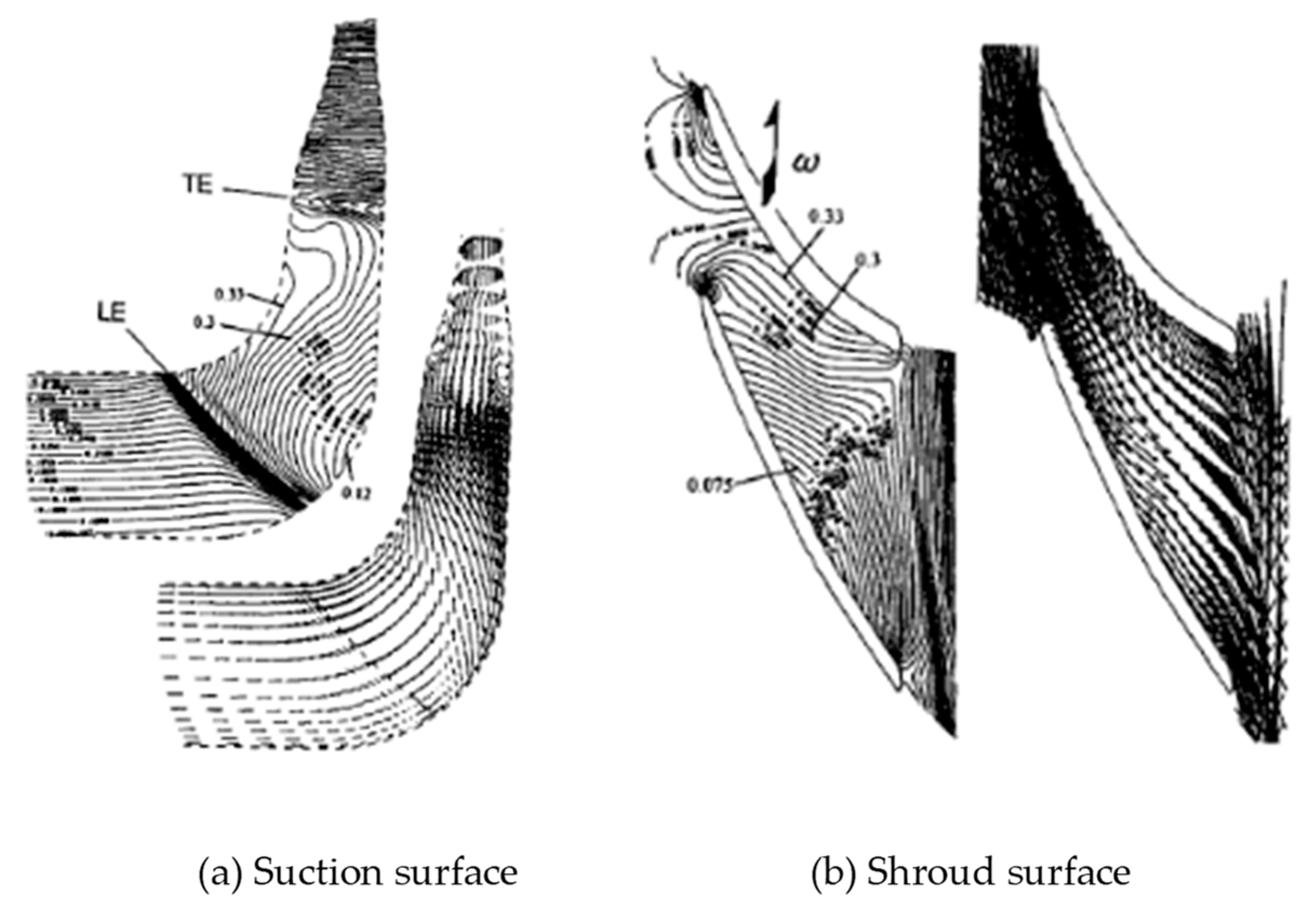
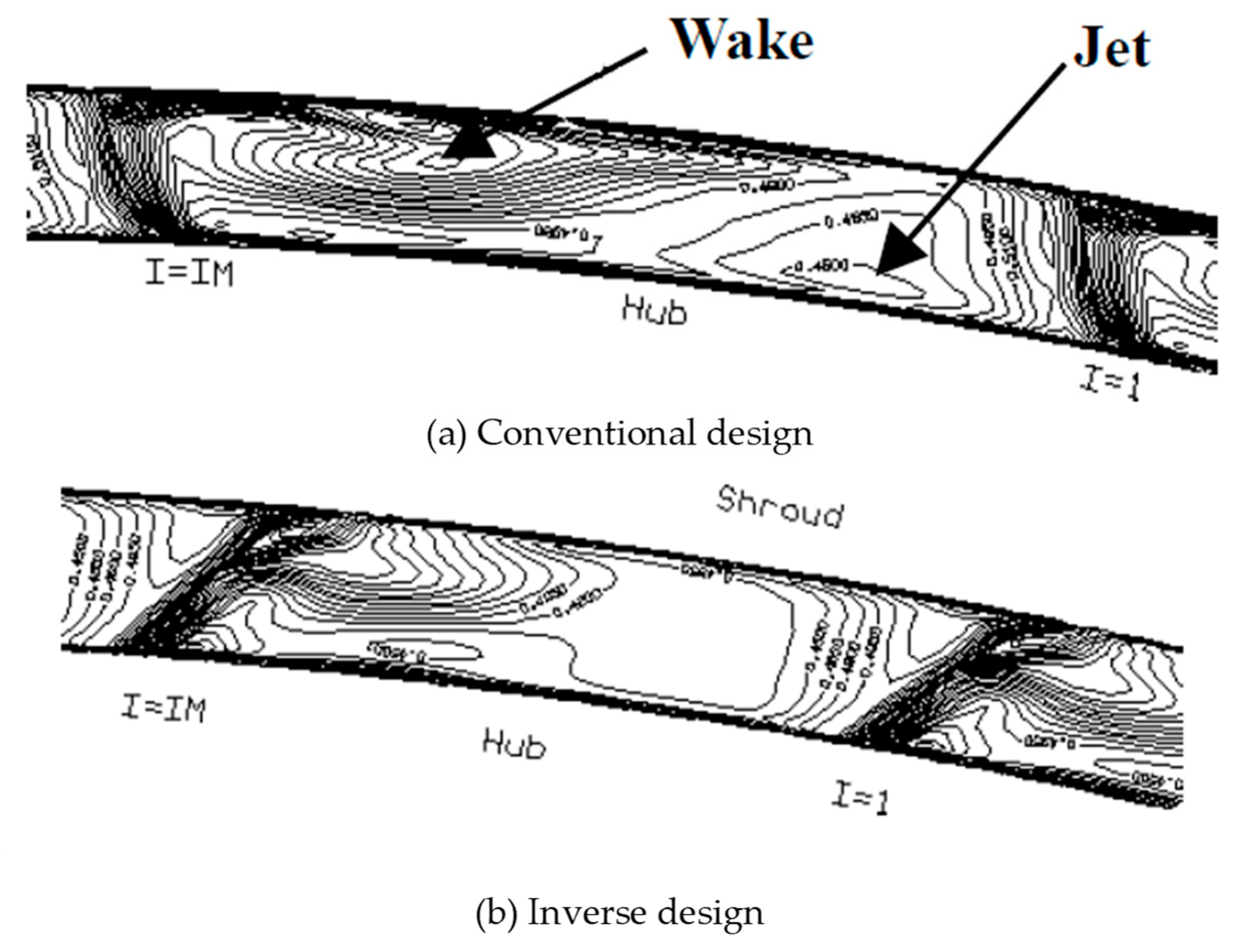
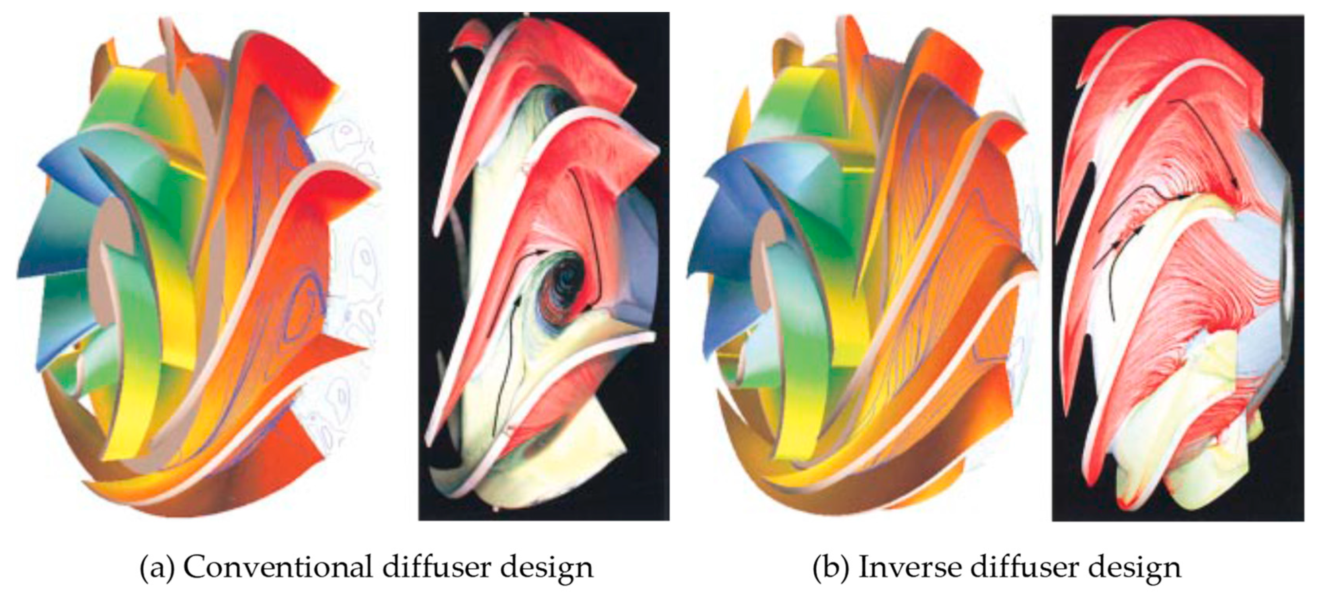
3.1. Suppression of Secondary Flow

The secondary flows in the impeller can cause exit flow non-uniformity of the impeller, blade channel vortex, and even rotating stall, which are all bad for the hydraulic performance of the machine. It is a real challenge for conventional design to control the secondary flows in the impeller since the relationship between the geometrical design parameters and the secondary flows is not clear. However, for IDM, it is more convenient to establish the relationship between the blade loading distribution and the secondary flows. According to Zangeneh [43], a simple kinematic equation can be derived for the development of secondary flows in an incompressible steady flow in a rotation system:
W ( W Ω ) = 2 Ω ( W ) W + Ω ( 2 ω × W )
where Ω is the vorticity vector, and ω is the rotation speed vector. W Ω is the streamwise component of vorticity, and it is defined as a secondary flow. It can be seen from Equation (19) that the secondary flows will show up when a component of streamline curvature or Coriolis in the direction of the vorticity vector exists. That is to say, the secondary flows are closely related to the magnitude of the streamline curvature and Coriolis acceleration. Based on the momentum equation for inviscid flow
( W ) W + 2 ω × W = 1 ρ p ω × ( ω × r ) = 1 ρ ( p ρ ω 2 r 2 2 ) = 1 ρ P r
where Pr is called reduced static pressure, we can find the direct relation between the gradient of Pr and the main causes of the secondary flows in a rotating system. Combining Equations (19) and (20), it can be found that if a gradient of the reduced static pressure in the direction of vorticity vector exists, the secondary flow will be generated there accordingly. Existing secondary flow suppression methods are based on this secondary flow theory to control the gradient of the reduced static pressure at certain positions of the flow field, and then the secondary flows can be suppressed [43].
The blade stacking condition is another important input parameter for the IDM, with blade geometry calculation based on flow-tangency condition, which can affect the spanwise gradients of the pressure coefficient between the hub and shroud. The blade lean can generate blade force, which has direct influence on the pressure distribution at both shroud and hub. For example, if the blades are leaned against the rotation direction as shown in Figure 2, for a centrifugal pump, the generated blade force will reduce the pressure at the hub and increase the pressure at the shroud. According to Zangeneh [43,44,45], a linear distribution of the wrap angle at the trailing edge, as shown in Figure 2 where the blade at the hub is leading the blade at the shroud in the rotation direction, is beneficial to secondary flow suppression for radial and mixed flow turbomachines.
In order to explain the above secondary flow control theory, an example of centrifugal pump redesign is discussed here. The simulated secondary flows in the conventional impeller of the centrifugal pump are shown in Figure 3, in which obvious secondary flows can be observed in the region from s = 0.3 to s = 0.5 (s denotes the unit meridional distance) on the suction surface corresponding to higher gradients of the reduced static pressure. The corresponding pressure distributions of the conventional impeller are shown in Figure 4, in which large values of ∆Cp can be found from s = 0.3 to s = 0.8, leading to strong secondary flows in the meridional channel shown in Figure 3a. According to the secondary flow control theory, the large value of ∆Cp in the region from s = 0.3 to s = 0.5 should be reduced to help reduce the large gradient of the reduced static pressure in this region. In order to do that, we can decrease ∆CBB by decreasing blade loading at the shroud and increase ∆CBB by increasing blade loading at the hub. Thus, an optimum blade loading as shown in Figure 5a is specified to redesign the conventional pump impeller, and the corresponding pressure distribution is shown in Figure 5b. Comparing the pressure distribution of the conventional impeller (Figure 4) and the inverse-designed impeller (Figure 5b), it can be found that the ∆Cp in the region from s = 0.3 to s = 0.5 is directly reduced. Based on the secondary flow control theory, we know that the secondary flows in this conventional pump impeller will be suppressed, which is confirmed by the velocity vector results of the redesigned impeller shown in Figure 6. It should be noted that the blade stacking condition in the redesigned impeller is also optimized based on the secondary flow control theory.
Goto et al. [10] applied above secondary flow control theory to pump design by tailoring both the blade loading distribution and blade stacking condition. The secondary flow in meridional channel is suppressed effectively, as shown in Figure 7. By using the ideal type of stacking condition as suggested by Zangeneh [43,44,45], the jet-wake flow pattern at the impeller exit is also suppressed, as shown in Figure 8.
The IDM can also be applied to design stationary components of the hydraulic machinery such as the pump inducer or the pump diffuser with vanes. The corner stall can be found in the diffuser designed by the conventional method, as shown in Figure 9a, which will deteriorate the general performance of the pump stage. By applying the secondary flow control approach to the design of the diffuser, the corner stall can be suppressed effectively, as shown in Figure 9b. All these applications verify the secondary flow control theory.
For different type of hydraulic machines, both the blade loading and stacking condition should be different; it depends on the specific flow conditions. By controlling blade loading parameters and stacking conditions (blade lean) simultaneously, the secondary flows can be minimized or suppressed effectively [20,43,44,45,46,47].

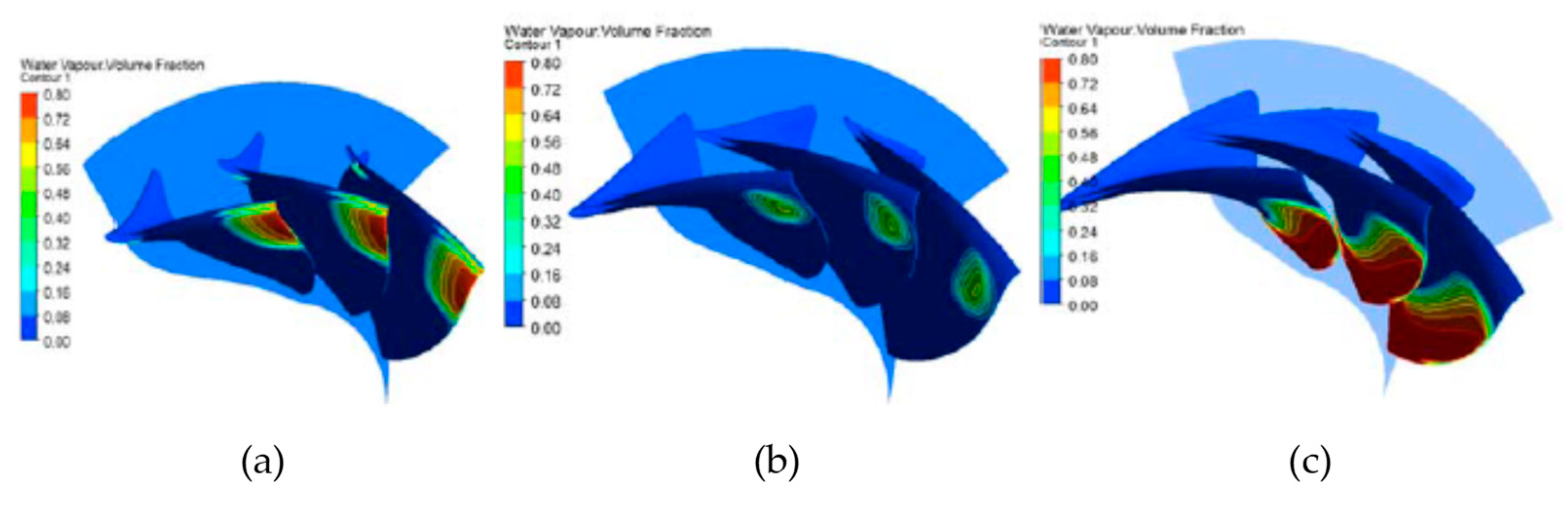
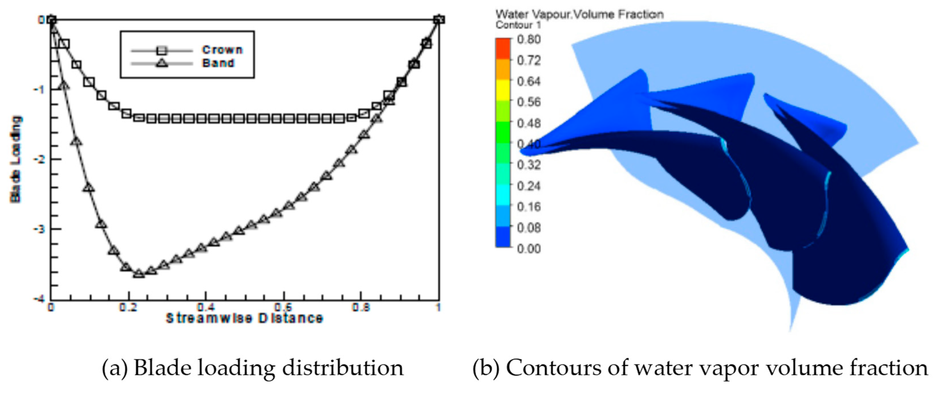
3.2. Suppression of Cavitation

In most cases, cavitation is harmful for hydraulic machinery. It often causes cavitation erosion, noise, and serious instability problems such as pressure fluctuation and narrow operating range. Suppression of cavitation is an important target for the design of hydraulic machinery. Normally, generation of cavitation is closely related to the static pressure distributions in the flow field. However, it is difficult to control the static pressure distribution since the internal flow of the impeller is complex, especially for the conventional design based on design experience. For IDM, it is convenient to control the static pressure distribution on blade surfaces by tailoring blade loading parameters rather than the blade geometry parameters. Normally, the low-pressure region happens at the position where the pressure load is large, and it can be suppressed by shifting the blade loading maximum to a different streamwise location. By doing this, the low-pressure region on blade surfaces can be controlled directly and effectively, and therefore the cavitation can be suppressed effectively [13,14,22] and the suction performance can be improved [48,49]. As mentioned above, the blade stacking condition (blade lean) can also have an influence on the static pressure distribution at specific positions of the impeller, and it can also be used to suppress cavitation [13,14,48].
Figure 10 and Figure 11 show an example of cavitation suppression in a Francis turbine by controlling blade loading and blade stacking conditions. As shown in Figure 10, by using different stacking conditions, cavitation performance of the turbine is different, and an optimal stacking condition exists. By carefully tailoring the blade loading distribution, the cavitation performance can be improved effectively, as shown in Figure 11. The area of a large volume fraction of the water vapor is reduced significantly by controlling the blade loading distribution as shown in Figure 11a.
The pressure distribution is strongly affected by even a very thin cavitation formation. Thus, there are issues related to the lack of a physical model of cavitation. This will be a serious problem when we attempt to create more detailed controls of cavitation-related phenomena by the inverse design method. Ashihara et al. [21] and Ashihara and Goto [22], however, have successfully applied IDM to control abnormal phenomena of rotating cavitations in turbopump inducers. They applied both the conventional method and the inverse method to design the pump inducer. Then, they tested the designed inducer for cavitation performance, and the inverse-designed inducer showed better cavitation performance, as shown in Figure 12. It is interesting that the physics have not been considered in their inverse design theory, but such abnormal phenomena can still be controllable by carefully tailoring the blade loading distribution.

4. Application of the Inverse Design Method to Optimization

Inverse design methods are often based on simplified flow equations such as potential flow theory or Euler equations [50] for efficient and robust calculations. The result will be different from the one obtained by solving Navier–Stokes equations, and the performance of the design outcome cannot be guaranteed. It is known that the flow in turbomachinery is completely turbulent, and flow calculation simplification (i.e., taking no account of viscosity) is always risky. Thus, the three-dimensional turbulence simulation technique based on the Navier–Stokes equation is usually applied to evaluate the performance of the design outcome and study the design know-how [13,48]. Therefore, in practical design applications, the inverse design method is often coupled with CFD tools (i.e., three-dimensional turbulence simulation technique) to optimize the hydrodynamic performance of the hydraulic machinery [51,52,53,54].
Design of hydraulic machinery is a multi-objective job, and multi-objective design approaches are necessary in order to find a compromise between sometimes conflicting objectives [55,56,57,58]. Normally, modern optimization work of hydraulic machinery can be divided into four steps. The first step is the parameterization design in which the turbomachinery is represented by a set of design parameters. The second step is the design process in which the turbomachinery is designed based on different sets of design parameters. The third step is the performance prediction based on CFD in which the performances of different designed machines are evaluated. Finally, a mathematical optimization algorithm is conducted to find the final optimum design. A typical multi-objective optimization process based on the inverse design method, CFD calculations, response surface methodology, and multi-objective genetic algorithm [56] is shown in Figure 13.
An optimization system based on IDM shows better performance than one based on the conventional design method, especially in terms of optimization time cost. Compared with the conventional design method, which mainly deals with geometrical parameters, fluid dynamic parameters such as pressure or blade loading are considered as the design parameters in the IDM. The fluid dynamic parameters show more direct influence on the hydraulic performance than the geometrical parameters, and it is more convenient to establish a relationship between fluid dynamic design parameters and hydrodynamic performance, which is favorable to the application of a surrogate model, such as the response surface model [56,57,58,59,60,61,62,63,64,65], in the inverse optimization design. At the same time, fewer numbers of fluid dynamic parameters are needed to represent the blade geometry compared to the geometrical parameters, and it is beneficial for the multi-objective optimization design of the hydraulic machinery. As a result, the IDM, three-dimensional turbulence simulation technique, and optimization algorithm are usually combined to solve the multi-objective optimization problem of the turbomachinery (as summarized in Table 1), and the design quality can be improved significantly [55,56,57,58,60,66,67,68].
As seen in Table 1, the inverse-design-based optimization methods have been applied successfully to different types of turbomachinery such as pumps, turbines, pump-turbines, compressors, and fans. The main design parameter is blade loading, and the number of the parameters is less than 10 in most cases. Fewer design parameters and the application of surrogate models, such as the response surface model, make the inverse-design-based optimization robust and efficient and more suitable for multi-objective optimization, even for multidiscipline optimization, which can be realized only by inducing the finite element analysis for structural performance calculation [59,65]. The inverse-design-based optimization not gives not only the optimal design of the turbomachinery but also an insight on the design know-how of different designed machines, which is helpful for the designer to further understand the performance of the design target with complex geometry and structure.

5. Conclusions

In this paper, the three-dimensional IDM based on potential flow theory and flow tangential condition for hydraulic machinery is reviewed. Compared with conventional design, which depends on design experience, the IDM reduces the impact of the design experience significantly by setting fluid dynamic parameters such as blade loading as input parameters. Due to the advantages of the IDM, it is usually coupled with turbulence simulation techniques and mathematical optimization algorithms to optimize the hydrodynamic performance of the machine. Optimization based on the IDM show obvious advantages in both time-cost and generality compared to the one based on conventional design method, since the main input parameter of IDM is the fluid dynamic parameter rather than the geometrical parameter prescribed. By controlling both the blade loading parameters and the blade stacking condition, the flow patterns such as secondary flow and cavitation can be suppressed effectively.
In conclusion, the future prospective of the IDM can be summarized as follows:
(1) Higher flow calculation accuracy with acceptable time-cost and reasonable convergence. For the IDM itself, improvement of flow calculation accuracy is its eternal pursuit. At the same time, high flow calculation accuracy leads to more time-cost and convergence problems that must be considered and solved in the actual applications.
(2) Specific design know-how and flow control approach for different hydraulic machinery based on the IDM. In contrast to conventional design methods, the main design parameters in the IDM are fluid dynamic parameters such as pressure and blade loading, which has more direct influence on the hydrodynamic performance of the machine. These fluid dynamic design parameters determine the quality of the design outcome directly. The internal flow in hydraulic machinery can be controlled effectively by carefully tailoring these parameters, and by doing this, the hydrodynamic performance can be improved. Therefore, another prospective of the IDM is to study the specific design know-how and flow control approach for different hydraulic machinery based on these fluid dynamic design parameters.
(3) Implant of the existing design experience into the IDM. Design experience plays an important role in the conventional design of hydraulic machinery. Many useful design experiences have been accumulated during decades of development of the design practice for hydraulic machinery. Most of these design experiences do not come from the inverse design practice; however, it is helpful to embed these useful design experiences into the IDM to improve the design quality.

Author Contributions

Conceptualization, W.Y.; methodology, W.Y.; validation, R.X. and W.Y.; investigation, W.Y.; resources, W.Y.; writing—original draft preparation, W.Y.; writing—review and editing, W.Y.; visualization, B.L.; supervision, W.Y.; project administration, W.Y.; funding acquisition, W.Y.

Funding

This research was funded by National Key Research and Development Plan (NKRDP), grant number 2018YFB0606103. The article processing charges were also funded by National Key Research and Development Plan.

Conflicts of Interest

The authors declare no conflict of interest.

References

  1. Hawthorne, W.R.; Wang, C.; McCune, J.E.; Tan, C.S. Theory of Blade Design for Large Deflections: Part I—Two-Dimensional Cascade. J. Eng. Gas Turbines Power 1984, 106, 346–353. [Google Scholar] [CrossRef]
  2. Hawthorne, W.R.; McCune, J.E.; Wang, C.; Tan, C.S. Theory of Blade Design for Large Deflections: Part II—Annular Cascades. J. Eng. Gas Turbines Power 1984, 106, 354–365. [Google Scholar] [CrossRef]
  3. Peng, G.; Cao, S.; Ishizuka, M.; Hayama, S. Design optimization of axial flow hydraulic turbine runner: Part I—An improved Q3D inverse method. Int. J. Numer. Methods Fluids 2002, 39, 517–531. [Google Scholar] [CrossRef]
  4. Cao, S.L.; Peng, G.; Yu, Z. Hydrodynamic Design of Rotodynamic Pump Impeller for Multiphase Pumping by Combined Approach of Inverse Design and CFD Analysis. J. Fluids Eng. 2005, 127, 330–338. [Google Scholar] [CrossRef]
  5. Wu, C.H. A General Theory of Three-Dimensional Flow in Subsonic and Supersonic Turbomachines of Axial-, Radial-, and Mixed-Flow Types; NASA Technical Reports Server NACA-TN-2604; Lewis Flight Propulsion Laboratory: Cleveland, OH, USA, 1952. [Google Scholar]
  6. Zangeneh, M. A compressible three-dimensional design method for radial and mixed flow turbomachinery blades. Int. J. Numer. Methods Fluids 1991, 13, 599–624. [Google Scholar] [CrossRef]
  7. Zangeneh, M. Development of a 3D Inverse Design Code for Application to Different Turbo and Hydraulic Machinery Components. In Proceedings of the JSME Centennial Grand Congress, Tokyo, Japan, 13–16 July 1997; Volume I, pp. 195–200. [Google Scholar]
  8. Borges, J.E. A Three-Dimensional Inverse Method for Turbomachinery: Part I—Theory. J. Turbomach. 1990, 112, 346–354. [Google Scholar] [CrossRef]
  9. Yin, J.; Wang, D. Review on applications of 3D inverse design method for pump. Chin. J. Mech. Eng. 2014, 27, 520–527. [Google Scholar] [CrossRef]
  10. Sogawa, Y.; Nohmi, M.; Sakurai, T.; Goto, A. Hydrodynamic Design System for Pumps Based on 3-D CAD, CFD, and Inverse Design Method. J. Fluids Eng. 2002, 124, 329–335. [Google Scholar]
  11. Ashihara, K.; Goto, A. Study on Pump Impeller with Splitter Blades Designed by 3-D Inverse Design Method. In Proceedings of the ASME Fluids Engineering Division Summer Meeting, Boston, MA, USA, 11–15 June 2000. [Google Scholar]
  12. Sakurai, T.; Saito, S.; Goto, A.; Ashihara, K. Pump Design System Based on Inverse Design Method and Its Application to Development of Diffuser Pump Series. In Proceedings of the 3rd ASME/JSME Joint Fluid Engineering Conference, San Francisco, CA, USA, 18–23 July 1999. [Google Scholar]
  13. Daneshkah, K.; Zangeneh, M. Parametric design of a Francis turbine runner by means of a three-dimensional inverse design method. IOP Conf. Ser. Earth Environ. Sci. 2010, 12, 12058. [Google Scholar] [CrossRef]
  14. Okamoto, H.; Goto, A. Suppression of Cavitation in a Francis Turbine Runner by Application of 3D Inverse Design Method. In Proceedings of the ASME Joint U.S.-European Fluids Engineering Division Conference, Montreal, QC, Canada, 14–18 July 2002. [Google Scholar]
  15. Zangeneh, M. Inverse Design of Centrifugal Compressor Vaned Diffusers in Inlet Shear Flows. J. Turbomach. 1996, 118, 385–393. [Google Scholar] [CrossRef]
  16. Zangeneh, M.; Schleer, M.; Pløger, F.; Roduner, C.; Ribi, B.; Abhari, R.S.; Hong, S.S. Investigation of an Inversely Designed Centrifugal Compressor Stage—Part I: Design and Numerical Verification. J. Turbomach. 2004, 126, 73–81. [Google Scholar] [CrossRef]
  17. Schleer, M.; Zangeneh, M.; Roduner, C.; Ribi, B.; Pløger, F.; Abhari, R.S.; Hong, S.S. Investigation of an Inversely Designed Centrifugal Compressor Stage—Part II: Experimental Investigations. J. Turbomach. 2004, 126, 82–90. [Google Scholar] [CrossRef]
  18. Goto, A.; Zangeneh, M. Compact Design of Diffuser Pumps Using Three-Dimensional Inverse Design Method. In Proceedings of the 3rd ASME/JSME Joint Fluids Engineering Conference, San Francisco, CA, USA, 18–23 July 1999. [Google Scholar]
  19. Goto, A.; Zangeneh, M. Hydrodynamic Design of Pump Diffuser Using Inverse Design Method and CFD, ASME. J. Fluids Eng. 2002, 124, 319–328. [Google Scholar] [CrossRef]
  20. Vogt, D.; Roduner, C.; Zangeneh, M. Improving a Vaned Diffuser for a Given Centrifugal Impeller by 3D Inverse Design. In Proceedings of the ASME Turbo Expo 2002: Power for Land, Sea, and Air, Amsterdam, The Netherlands, 3–6 June 2002. [Google Scholar]
  21. Ashihara, K.; Goto, A.; Kamijo, K.; Yamada, H. Improvements of Inducer Inlet Backflow Characteristics Using 3-D Inverse Design Method. In Proceedings of the 38th AIAA/ASME/SAE/ASEE Joint Propulsion Conference & Exhibit, Indianapolis, IN, USA, 7–10 July 2002. [Google Scholar] [CrossRef]
  22. Ashihara, K.; Goto, A. Effects of Blade Loading on Pump Inducer Performance and Flow Fields. In Proceedings of the ASME 2002 Joint U.S.-European Fluids Engineering Division Conference, Montreal, QC, Canada, 14–18 July 2002. [Google Scholar] [CrossRef]
  23. Zangeneh, M. Inviscid-Viscous Interaction Method for Three-Dimensional Inverse Design of Centrifugal Impellers. J. Turbomach. 1994, 116, 280–290. [Google Scholar] [CrossRef]
  24. Molinari, M.; Dawes, W.N. Review of evolution of compressor design process and future perspectives. Proc. Inst. Mech. Eng. Part C J. Mech. Eng. Sci. 2006, 220, 761–771. [Google Scholar] [CrossRef]
  25. Page, J.H.; Watson, R.; Ali, Z.; Hield, P.; Tucker, P.G. Advances of Turbomachinery Design Optimization. In Proceedings of the 53rd AIAA Aerospace Sciences Meeting, Kissimmee, FL, USA, 5–9 January 2015. [Google Scholar]
  26. Páscoa, J.; Mendes, A.; Gato, L.; Páscoa, J. A fast iterative inverse method for turbomachinery blade design. Mech. Res. Commun. 2009, 36, 630–637. [Google Scholar] [CrossRef]
  27. Choo, B.M.F.; Zangeneh, M. Development of an (Adaptive) Unstructured 2-D Inverse Design Method for Turbomachinery Blades. In Proceedings of the ASME Turbo Expo 2002: Power for Land, Sea, and Air, Amsterdam, The Netherlands, 3–6 June 2002. [Google Scholar]
  28. Roidl, B.; Ghaly, W. Dual Point Redesign of Axial Turbines Using a Viscous Inverse Design Method. In Proceedings of the ASME Turbo Expo: Power for Land, Sea, and Air, Orlando, FL, USA, 8–12 June 2009. [Google Scholar]
  29. Mohammad, T.R. A Viscous Inverse Design Method for Internal and External Flow over Airfoils Using CFD Techniques. In Proceedings of the V European Conference on Computational Fluid Dynamics, Lisbon, Portugal, 14–17 June 2010. [Google Scholar]
  30. Daneshkhah, K.; Ghaly, W. Aerodynamic Inverse Design for Viscous Flow in Turbomachinery Blading. J. Propuls. Power 2007, 23, 814–820. [Google Scholar] [CrossRef]
  31. Daneshkhah, K.; Ghaly, W. An Inverse Blade Design Method for Subsonic and Transonic Viscous Flow in Compressors and Turbines. Inverse Probl. Sci. Eng. 2006, 14, 211–231. [Google Scholar] [CrossRef]
  32. Daneshkhah, K.; Ghaly, W. An inverse design method for viscous flow in turbomachinery blading using a wall virtual movement. Inverse Probl. Sci. Eng. 2009, 17, 381–397. [Google Scholar] [CrossRef]
  33. Roidl, B.; Ghaly, W. Redesign of a Low Speed Turbine Stage Using a New Viscous Inverse Design Method. J. Turbomach. 2010, 133, 011009. [Google Scholar] [CrossRef]
  34. Thompkins, W.T.; Tong, S.S. Inverse or Design Calculations for Nonpotential Flow in Turbomachinery Blade Passages. J. Eng. Power 1982, 104, 281–285. [Google Scholar] [CrossRef]
  35. Tong, S.S.; Thompkins, W.T. A Design Calculation Procedure for Shock-Free or Strong Passage Shock Turbomachinery Cascades. J. Eng. Power 1983, 105, 369–376. [Google Scholar] [CrossRef]
  36. Ferlauto, M.; Marsilio, R. A viscous inverse method for aerodynamic design. Comput. Fluids 2006, 35, 304–325. [Google Scholar] [CrossRef] [Green Version]
  37. Mohammad, T.R. Inverse Approach to Turbomachinery Blade Design. AIAA J. 2009, 47, 703–709. [Google Scholar] [CrossRef]
  38. Yang, J.G.; Liu, Y.; Wang, X.F. 3D Viscous Inverse Design of Turbomachinery Using One-Equation Turbulence Model. In Proceedings of the ASME Turbo Expo: Turbomachinery Technical Conference & Exposition, Seoul, Korea, 13–17 June 2016. [Google Scholar]
  39. Yang, J.; Liu, Y.; Wang, X.; Wu, H. An Improved Steady Inverse Method for Turbomachinery Aerodynamic Design. Inverse Probl. Eng. 2017, 25, 633–651. [Google Scholar] [CrossRef]
  40. Qiu, X.; Ji, M.; Dang, T. Three-Dimensional Viscous Inverse Method for Axial Blade Design. Inverse Probl. Eng. 2009, 17, 1019–1036. [Google Scholar] [CrossRef]
  41. Demeulenaere, A.; Léonard, O.; Van den Braembussche, R. A two-dimensional Navier—Stokes inverse solver for compressor and turbine blade design. Proc. Inst. Mech. Eng. Part A J. Power Energy 1997, 211, 299–307. [Google Scholar] [CrossRef]
  42. De Vito, L.L.; Van den Braembussche, R.A.; Deconinck, H. A Novel Two-Dimensional Viscous Inverse Design Method for Turbomachinery Blading. J. Turbomach. 2003, 125, 310–316. [Google Scholar] [CrossRef]
  43. Zangeneh, M.; Goto, A.; Harada, H. On the Design Criteria for Suppression of Secondary Flows in Centrifugal and Mixed Flow Impellers. J. Turbomach. 1998, 120, 723–735. [Google Scholar] [CrossRef]
  44. Zangeneh, M.; Goto, A.; Takemura, T. Suppression of Secondary Flows in a Mixed-Flow Pump Impeller by Application of 3D Inverse Design Method: Part 1—Design and Numerical Validation. In Proceedings of the ASME 1994 International Gas Turbine and Aeroengine Congress and Exposition, The Hague, The Netherlands, 13–16 June 1994. [Google Scholar]
  45. Goto, A.; Takemura, T.; Zangeneh, M. Suppression of Secondary Flows in a Mixed-Flow Pump Impeller by Application of 3D Inverse Design Method: Part 2—Experimental Validation. In Proceedings of the ASME. Turbo Expo: Power for Land, Sea, and Air, The Hague, The Netherlands, 13–16 June 1994; Volume 1. [Google Scholar] [CrossRef]
  46. Ashihara, K.; Goto, A. Improvements of pump suction performance using 3D inverse design method. In Proceedings of the 3rd ASME/JSME Joint Fluid Engineering Conference, San Francisco, CA, USA, 18–23 July 1999. [Google Scholar]
  47. Watanabe, H.; Harada, H. Suppression of Secondary Flows in a Turbine Nozzle with Controlled Stacking Shape and Exit Circulation by 3D Inverse Design Method. In Proceedings of the ASME. Turbo Expo: Power for Land, Sea, and Air, Indianapolis, IN, USA, 7–10 June 1999; Volume 1. [Google Scholar] [CrossRef]
  48. Bonaiuti, D.; Zangeneh, M.; Aartojarvi, R.; Eriksson, J. Parametric Design of a Waterjet Pump by Means of Inverse Design, CFD Calculations and Experimental Analyses. J. Fluids Eng. 2010, 132, 031104. [Google Scholar] [CrossRef]
  49. Zangeneh, M.; Goto, A.; Harada, H. On the Role of Three-Dimensional Inverse Design Methods in Turbomachinery Shape Optimization. Proc. Inst. Mech. Eng. Part C J. Mech. Eng. Sci. 1999, 213, 27–42. [Google Scholar] [CrossRef]
  50. Taddei, S.R.; Larocca, F. Euler-based Throughflow Method for Inverse Design and Optimization of Turbomachinery Blades. Prog. Comput. Fluid Dyn. 2014, 14. [Google Scholar] [CrossRef]
  51. Maillard, M.; Zangeneh, M. Application of 3D Inverse Design Based Multi-Objective Optimization of Axial Cooling Fan with Large Tip Gab; SAE Technical Paper; SAE International: Detroit, MI, USA, 2014. [Google Scholar] [CrossRef]
  52. Watanabe, H.; Tsukamoto, H. Design Optimization of Cryogenic Pump Inducer Considering Suction Performance and Cavitation Instability. In Proceedings of the ASME-JSME-KSME Joint Fluids Engineering Conference, Hamamatsu, Japan, 24–29 July 2011. [Google Scholar]
  53. Kerschberger, P.; Gehrer, A. Hydraulic Development of High Specific-speed Pump-turbines by Means of an Inverse Design Method, Numerical Flow Simulation (CFD) and Model Testing. In Proceedings of the 25th IAHR Symposium on Hydraulic Machinery and Systems, Timisoara, Romania, 20–24 September 2010. [Google Scholar] [CrossRef]
  54. Ashihara, K.; Guo, S.J.; Goto, A.; Okamoto, H. Optimization of Microturbine Aerodynamics Using CFD, Inverse Design and FEM Structural Analysis: 1st Report: Compressor Design. In Proceedings of the ASME Turbo Expo 2004: Power for Land, Sea, and Air, Vienna, Austria, 14–17 June 2004. [Google Scholar] [CrossRef]
  55. Ashihara, K.; Guo, S.J.; Goto, A.; Okamoto, H. Optimization of Microturbine Aerodynamics Using CFD, Inverse Design and FEM Structural Analysis: 2nd Report: Turbine Design. In Proceedings of the ASME Turbo Expo 2004: Power for Land, Sea, and Air, Vienna, Austria, 14–17 June 2004. [Google Scholar] [CrossRef]
  56. Zangeneh, M.; Daneshkhah, K. A Fast 3D Inverse Design Based Multi-Objective Optimization Strategy for Design of Pumps. In Proceedings of the ASME 2009 Fluids Engineering Division Summer Meeting, Vail, CO, USA, 2–6 August 2009. [Google Scholar]
  57. Yang, W.; Xiao, R. Multiobjective Optimization Design of a Pump–Turbine Impeller Based on an Inverse Design Using a Combination Optimization Strategy. J. Fluids Eng. 2013, 136, 014501. [Google Scholar] [CrossRef]
  58. Bonaiuti, D.; Zangeneh, M. On the Coupling of Inverse Design and Optimization Techniques for Turbomachinery Blade Design. In Proceedings of the ASME. Turbo Expo: Power for Land, Sea, and Air, Barcelona, Spain, 8–11 May 2006; Volume 6. [Google Scholar]
  59. Zhu, B.; Wang, X.; Tan, L.; Zhou, D.; Zhao, Y.; Cao, S. Optimization design of a reversible pump–turbine runner with high efficiency and stability. Renew. Energy 2015, 81, 366–376. [Google Scholar] [CrossRef]
  60. Zangeneh, M.; Mendonça, F.; Hahn, Y.; Cofer, J. 3D Multi-Disciplinary Inverse Design Based Optimization of a Centrifugal Compressor Impeller. In Proceedings of the ASME. Turbo Expo: Power for Land, Sea, and Air, Düsseldorf, Germany, 16–20 June 2014; Volume 2B. [Google Scholar] [CrossRef]
  61. Bonaiuti, D.; Zangeneh, M. On the Coupling of Inverse Design and Optimization Techniques for the Multiobjective, Multipoint Design of Turbomachinery Blades. J. Turbomach. 2009, 131, 021014. [Google Scholar] [CrossRef]
  62. Lu, Y.M.; Wang, X.F.; Wang, W.; Zhou, F.M. Application of the Modified Inverse Design Method in the Optimization of the Runner Blade of a Mixed-Flow Pump. Chin. J. Mech. Eng. 2018, 131. [Google Scholar] [CrossRef]
  63. Ma, Z.; Zhu, B.S.; Rao, C.; Shangguan, Y.H. Comprehensive Hydraulic Improvement and Parametric Analysis of a Francis Turbine Runner. Energies 2019, 12, 307. [Google Scholar] [CrossRef]
  64. Liu, L.H.; Zhu, B.S.; Bai, L.; Liu, X.B.; Zhao, Y. Parametric Design of an Ultrahigh-Head Pump-Turbine Runner Based on Multiobjective Optimization. Energies 2017, 10, 1169. [Google Scholar] [CrossRef]
  65. Takayama, Y.; Watanabe, H. Multi-objective Design Optimization of a Mixed-flow Pump. In Proceedings of the ASME 2009 Fluids Engineering Division Summer Meeting, Vail, CO, USA, 2–6 August 2009. [Google Scholar] [CrossRef]
  66. Zhang, J.; Zangeneh, M.; Eynon, P. A 3D Inverse Design Based Multidisciplinary Optimization on the Radial and Mixed-inflow Turbines for Turbochargers. In Proceedings of the 11th International Conference on Turbochargers and Turbocharging, London, UK, 13–14 May 2014. [Google Scholar]
  67. Reis, C.J.B.; Manzanares-Filho, N.; De Lima, A.M.G. Robust Optimization of Turbomachinery Cascades Using Inverse Methods. J. Braz. Soc. Mech. Sci. Eng. 2016, 38, 297–305. [Google Scholar] [CrossRef]
  68. Yiu, K.F.C.; Zangeneh, M. Three-Dimensional Automatic Optimization Method for Turbomachinery Blade Design. J. Propuls. Power 2000, 16, 1174–1181. [Google Scholar] [CrossRef]
  69. Huang, R.F.; Luo, X.W.; Ji, B.; Wang, P.; Yu, A.; Zhai, Z.H.; Zhou, J.J. Multi-objective Optimization of a Mixed-Flow Pump Impeller Using Modified NSGA-II Algorithm. Sci. China Technol. Sci. 2015, 58, 2111–2130. [Google Scholar] [CrossRef]
  70. Wang, P.; Vera-Morales, M.; Vollmer, M.; Zangeneh, M.; Zhu, B.S.; Ma, Z. Optimization of a Pump-as-turbine Runner Using a 3D Inverse Design Methodology. In Proceedings of the 29th IAHR Symposium on Hydraulic Machinery and Systems, Kyoto, Japan, 16–21 September 2018; Volume 240. [Google Scholar]
  71. Ashihara, K.; Goto, A. Turbomachinery Blade Design Using 3-D Inverse Design Method, CFD and Optimization Algorithm. In Proceedings of the ASME. Turbo Expo: Power for Land, Sea, and Air, New Orleans, LA, USA, 4–7 June 2001; Volume 1. V001T03A053. [Google Scholar] [CrossRef]
  72. Hu, Z.N.; Zhu, B.S.; Liu, X.B.; Ma, Z.; Xue, C. Multiobjective Optimization Design of Ultrahigh-head Pump Turbine Runners with Splitter Blades. In Proceedings of the 29th IAHR Symposium on Hydraulic Machinery and Systems, Kyoto, Japan, 16–21 September 2018; Volume 240. [Google Scholar] [CrossRef]
  73. Zhu, Y.J.; Ju, Y.P.; Zhang, C.H. An Experience-independent Inverse Design Optimization Method of Compressor Cascade Airfoil. J. Power Energy 2018, 233. [Google Scholar] [CrossRef]
  74. Boselli, P.; Zangeneh, M. An Inverse Design Based Methodology for Rapid 3D Multi-objective/multidisciplinary of Axial Turbines. In Proceedings of the ASME 2011 Turbo Expo: Turbine Technical Conference and Exposition, Vancouver, BC, Canada, 6–10 June 2011. [Google Scholar] [CrossRef]
Figure 1. Flow chart for the basic calculation process of the inverse design method.
Energies 12 03210 g001
Figure 2. Effect of blade lean on pressure distribution.
Energies 12 03210 g002
Figure 3. Simulated velocity vectors and reduced static pressure on both the suction surface and shroud surface of the blade [43].
Energies 12 03210 g003
Figure 4. Calculated pressure coefficient Cp distribution on both the pressure surface and suction surface at the shroud and hub, respectively, for the conventional impeller [43].
Energies 12 03210 g004
Figure 5. Blade loading specified based on secondary flow control theory and corresponding pressure distribution [43].
Energies 12 03210 g005
Figure 6. Simulated velocity vectors on both the suction surface and shroud surface of the blade [43].
Energies 12 03210 g006
Figure 7. Velocity vectors on the blade suction surface [10].
Energies 12 03210 g007
Figure 8. Velocity contour at the impeller trailing edge [10].
Energies 12 03210 g008
Figure 9. Diffuser design with suppressed corner stall [34].
Energies 12 03210 g009
Figure 10. Contours of water vapor volume fraction at (a) –15 degree, (b) –30 degree, and (c) –45 degree stacking design conditions [13].
Energies 12 03210 g010
Figure 11. Suppression of cavitation based on blade loading control [13].
Energies 12 03210 g011
Figure 12. Cavitation visualization of different pump inducers in the experiment. ICHA represents conventional design of pump inducer, and INVA and INVB represent inverse designs of pump inducers with different blade loading distributions [22].
Energies 12 03210 g012
Figure 13. A typical multi-objective optimization process based on the inverse design method [56].
Energies 12 03210 g013
Table 1. Applications of the inverse-design based optimization method to different types of turbomachinery. IDM—inverse design method, DoE—design of experiment, CFD—computational fluid dynamics, PSA—parameter sensitivity analysis, MOGA—multi-objective genetic algorithm, NSGA—non-dominated sorting genetic algorithm, RSM—response surface methodology, SLP—sequential linear programming, EP—exterior penalty, SA—simulated annealing, GA—genetic algorithm, RBNN—radial basis neural network, RBF—radial basis function, FEA—finite element analysis, AM—adjoint method.
TargetDesign ParametersOptimization ObjectivesOptimization AlgorithmImprovement of PerformanceReferences
Pump inducerBlade loading at both hub and tip
(5 parameters in total)
(1) Inducer head and efficiency
(2) Cavity volume
(3) Dispersion of cavity length
IDM + DoE + CFD + PSASuction performance and cavitation instability improved[51]
Mixed flow pumpBlade loading at hub, midspan and shroud [68]; Blade stacking [55,69]
Wrap angles [61]
(8 to 13 parameters in total)
(1) NPSHr, Impeller leading edge sweep angle [55]
(2) Efficiency, Pump head [61,69]
(3) Efficiency, maximum slope in flow-head curve, and shut-off power/head [64]
(4) Efficiency, suction specific speed [68]
IDM + CFD + MOGA/NSGA-II [55,61]
IDM + DoE + CFD + RSM + MOGA [64]
IDM + CFD + SLP/EP/SA/GA [68]
IDM + DoE + CFD + RBNN + NSGA-II [69]
Cavitation performance improved and leading edge sweep reduced [55]
Performances at both design and off-design point improved [61,69]
Efficiency and suction performance improved [68]
[55,61,64,68,69]
Pump-turbine/Pump as turbineBlade loading at both hub and shroud; Blade stacking; Meridional channel geometry [58]
(6 to 9 parameters in total)
(1) Pump mode efficiency/profile loss
(2) Turbine mode efficiency/profile loss
(3) Minimum pressure at the blade surface [58,63]
(4) Secondary loss factor [70]
IDM + DoE + CFD + RSM/RBF + MOGABoth energy and stability performance in both pump and turbine mode improved[56,58,63,70,71]
TurbineBlade loading at both hub and shroud; Blade stacking; Meridional channel geometry; Thickness [65,72]
(11 to 17 parameters in total)
(1) Efficiency
(2) Minimum pressure on the blade surfaces
(3) Mass flow parameter [65]
(4) Blade lean, stress factor [72]
IDM + DoE + CFD + RSM + NSGA-II [61]
IDM + DoE + CFD + FEA + RSM + PSA [65]
IDM + CFD + FEA + NSGA-II [72]
Efficiency at both design and off-design point improved [62,65]
Efficiency and structural performance improved [72]
[62,65,72]
Compressor/Fan Blade loading at both hub and shroud; Blade stacking; Meridional channel geometry; Blade geometry (16 parameters in total) [73]
(4 to 12 parameters in total)
(1) Efficiency
(2) Choke margin
(3) Peak stress [59]
(4) Entropy, blockage [67]
(5) Leakage loss, profile loss [74]
(6) Pressure distribution [73]
IDM + DoE + CFD/FEA ([59]) + RSM + MOGA
IDM + CFD + MOGA [74]
IDM + CFD + GA + AM [73]
Both design and off-design performance improved; Structural integrity optimized [58][57,59,60,67,73,74]

