Article

A Game Theory-Based Approach for Vulnerability Analysis of a Cyber-Physical Power System

1
School of Electrical Engineering, Zhejiang University, Hangzhou 310027, China
2
Department for Management of Science and Technology Development, Ton Duc Thang University, Ho Chi Minh City 800010, Vietnam
3
Faculty of Electrical and Electronics Engineering, Ton Duc Thang University, Ho Chi Minh City 800010, Vietnam
4
UNSW Business School, The University of New South Wales, Sydney, NSW 2052, Australia
5
Guangzhou Power Supply Company Limited, Guangzhou 510620, China
*
Author to whom correspondence should be addressed.
Energies 2019, 12(15), 3002; https://doi.org/10.3390/en12153002
Submission received: 20 June 2019 / Revised: 31 July 2019 / Accepted: 1 August 2019 / Published: 3 August 2019

Abstract

:
In a Cyber-Physical Power System (CPPS), the interaction between the power cyber system and the power physical system becomes more extensive and more in-depth. The failure of a cyber component could have an impact on the security and reliability of the power physical system. Existing publications have focused on the impacts of the power cyber network on the power physical network, while a general CPPS model considering the mutual impacts of these two networks is less studied. Given this background, a game-theoretic approach for a cyber-physical power system vulnerability analysis is proposed. First, a CPPS interactive model framework is structured, consisting of five types of elements: P-nodes, PP-links, C-nodes, CC-links and CP-links. The interactions among these elements are considered. On this basis, the system cascading failure under potential attacks is analyzed, followed with an optimal load curtailment operation when in an emergency. To further illustrate the system vulnerability, a bi-level optimization model under a game-theoretic framework is presented to describe the interactions between a CPPS attacker and a system defender. Optimal resource allocation by the system defender for maintaining system reliability can be obtained by solving the problem. The feasibility and effectiveness of the proposed method are demonstrated by a revised version of the IEEE 14-bus power system.

1. Introduction

A power system is one of the most complicated and delicate engineering systems in the world. Its complexity increases even more as a number of advanced devices such as distributed generators, energy storage, and a massive amount of monitoring devices are integrated into the power system. The concept of a Cyber-Physical System (CPS) was introduced to describe a next-generation engineered system covering functions of communication, computing, and control [1]. The power system integrated with monitoring devices is a typical Cyber-Physical System, and therefore forming a Cyber-Physical Power System (CPPS).
In a CPPS, each of the power, information, and communication infrastructures is governed by its own physical or logical laws. The power systems benefit from the development of information technology by both economic boost and reliability improvements [2]. The more precise and trustful the data provided by information infrastructures is, the more it increases the efficiency of the power utility [3]. By recognizing and isolating faults with higher accuracy, the CPPS is able to operate in a better manner, in terms of improved reliability [4].
However, in addition to being vulnerable to failures or attacks on a physical power network as in traditional power systems, a CPPS is also prone to malicious attacks on the cyber network. The Ukraine blackout in 2015 is a typical coordinated cyber physical attack (CCPA) case where the physical attack is masked by coordinated cyberattacks.
In the 2015 Ukraine blackout case, the attacker launched several attacks simultaneously. By using BlackEnergy 3 malware, the hackers took control of the computers in the Ukraine power system control center, and opened breakers to bring at least thirty substations off-line. Meanwhile a telephonic denial-of-service attack was launched to postpone the reports of the outage. The CCPA in this case caused power outage affecting at least 225,000 customers for several hours [5].
It is essential to build a CPPS model as the basis for research in vulnerability assessment, malicious attack detection, and optimization in CPPSs. For example, a hybrid system model is described in [6] where both a continuous power system model and a discrete information system model were integrated. There are also researches focusing on the CPS modeling for other CPS systems such as computer systems and control systems. A taxonomy for description of attacks on CPS is presented in [7,8]. A distributed unmanned aerial vehicles architecture is developed in [9] to characterize attacks and their propagation.
Based on the given literature review, this paper presents a vulnerability assessment procedure of a CPPS considering virtual cyber-physical links. The main contributions of this paper are threefold:
(1)
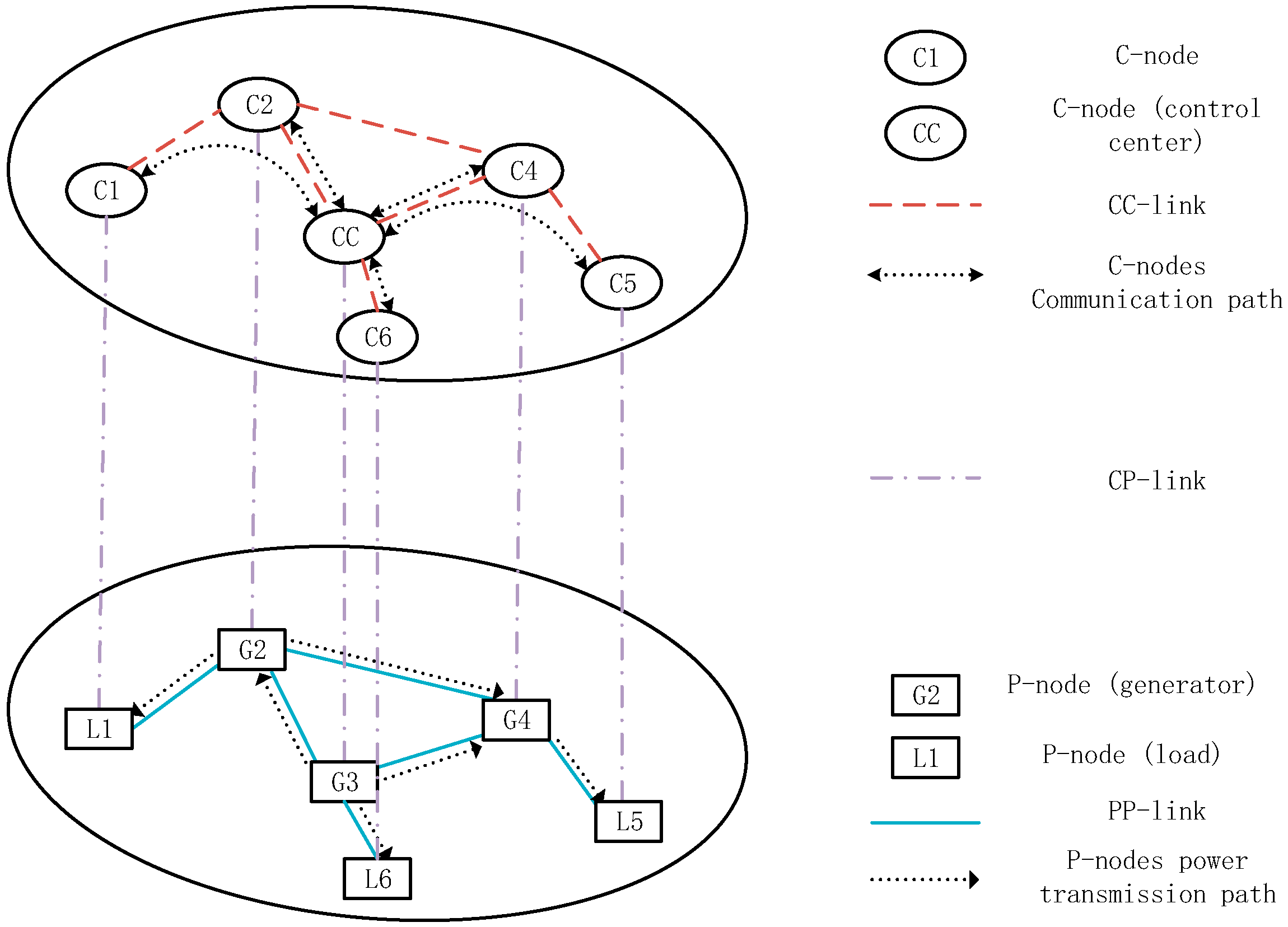
A comprehensive CPPS interactive model framework is developed. The CPPS components are classified into five categories (i.e., physical nodes, cyber nodes, physical-physical links, cyber-cyber links, and cyber-physical links). The interaction between cyber components and physical components is discussed by analyzing the optimal load curtailment operation upon component failure.
(2)
A game-theoretic bi-level optimization model for the CPPS attacker and defender is proposed. At the upper level, the defender manages the defending resources to minimize the worst-case load loss caused by the attacks. At the lower level, the attacker decides which component (or components) to attack so that the load loss could be maximized. The hierarchical interactions between the defender and the attacker are described in a game-theoretic model.
(3)
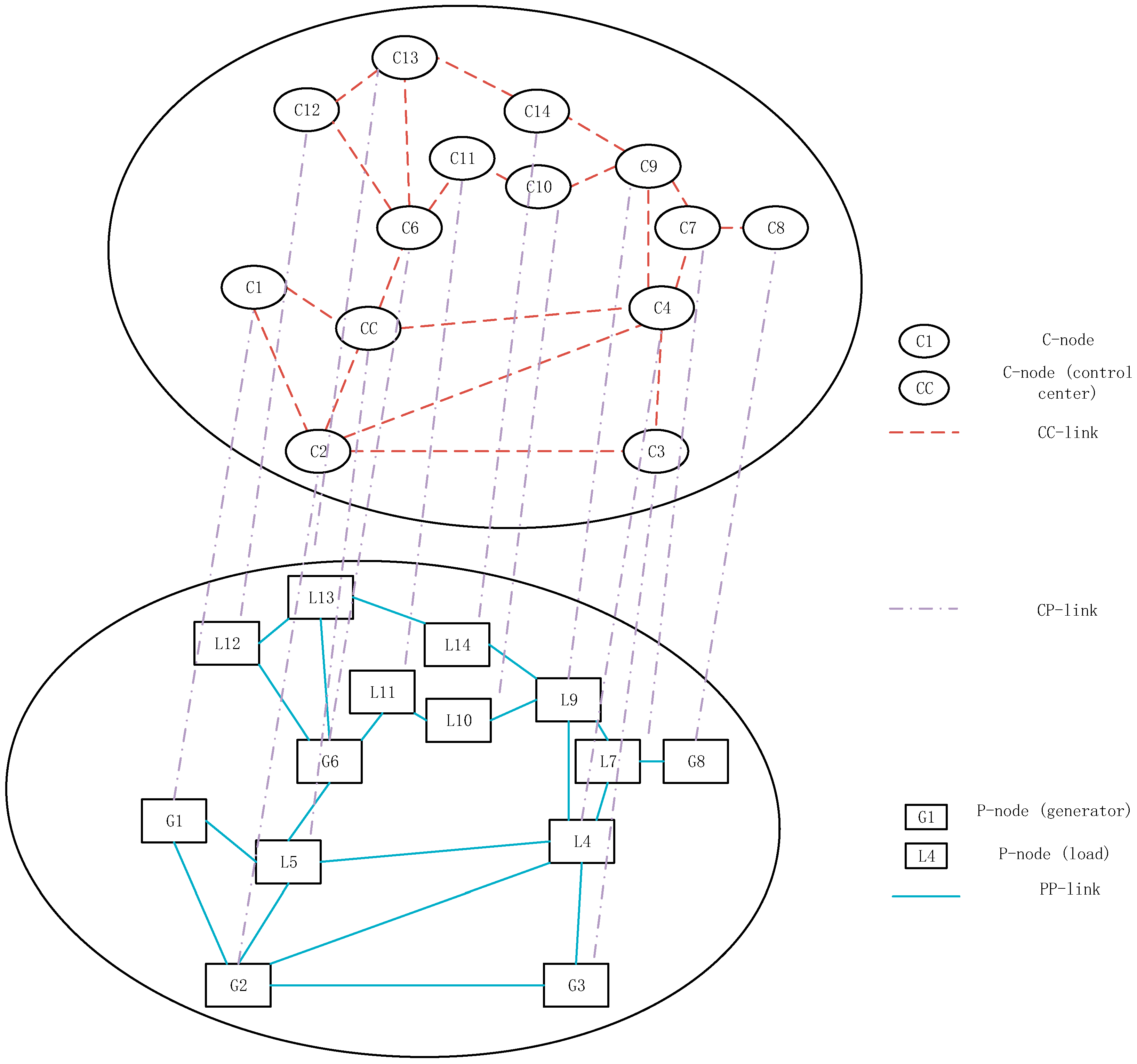
The proposed model is illustrated based on a revised version of the IEEE 14-bus power system. The defender’s strategy (i.e., the distribution of the defending resources) can be viewed as the relative vulnerability index among the CPPS components. This result can be further developed to calibrate the defender’s decisions on the system.
The remainder of this paper is organized as follows: Section 2 describes the related work. Section 3 presents a CPPS node-link model, which considers virtual cyber-physical links. Section 4 analyzes the CPPS cascading failure under malicious attacks, followed by an optimal load curtailment operation when in an emergency. Section 5 discusses the bi-level optimization problem between the malicious attacker and the system defender. Section 6 illustrates the effectiveness of the proposed models with the simulation results. Conclusions and future work are given in Section 7.

2. Related Work

2.1. Cyber Data Attacks in CPPSs

An attack on either the power network or the cyber network will no doubt damage the power system [10]. As malicious attacks generally occur in intelligent ways, modeling attacks with accurate mathematical models is challenging. Researchers have explored some specific attacks. For example, integrity attacks on state estimation systems are studied in [11,12], where the integrity of sensor measurements could be damaged by integrity attacks. The problems of estimation and control of linear systems with several sensors hijacked by deception attacks are considered in [13]. In [14,15], false data injection attacks (FDIAs) are explored in the state estimation frameworks for power systems. Generally, FDIAs can be considered as a specific version of integrity attack, where an adversary could launch attacks to inject fake information into the measurement system of a CPPS, and eventually bypass the existing bad data detection scheme, with the knowledge of the power system configuration. In [16], a specific FDIA called a fake-acknowledge attack against a remote state estimation is considered, where the online power schedule signal from the remote estimator might be falsified by attackers. The optimal strategies for both attackers and defenders are explored with the aid of a game-theoretic framework. Denial-of-service (DoS) attacks are studied in [10] for the state estimation of CPSs where an attacker jams the wireless cyber network. DoS attacks are launched aiming to prevent information transmission between CPS components by jamming the cyber network. Interfering with the radio frequencies is a DoS attack technique that is frequently used [17,18]. In [10], the interactive decision-making process of both information transmission and attacker launching attacks is investigated by formulating a game-theoretic framework. The optimal attack strategy that maximizes the impact of DoS attacks on CPSs is explored in [18,19]. In [20], another form of attacks, i.e. replay attacks, is studied.
The coordinated cyber physical attacks (CCPAs) are also a great concern in the CPPS. It is shown in [21] that CCPAs could be detected through online tracking of the power system equivalent impedance. In [22], a single-level optimization model is constructed to identify the meters that should be protected from attacks. In [23], linear algebra and graph theory are used to develop methods for information recovery of the system under CCPAs.

2.2. Cyber-Physical Mutual Impacts Analysis

CPPS modeling normally starts with analyzing the mutual coupling effect between power networks and cyber networks. A method to solve the communication delay problem in load frequency control is proposed in [24] based on a linear matrix inequality. By modeling the information system as a feedback module, [25] proposes a cyber-based dynamical modeling approach for describing the CPPS. In [26], the cascading failures in an interdependent network are modeled, with the percolation theory of the network considered. The vulnerability of the interdependent network was assessed in [27]. The interdependency model of a power network and a cyber network is studied in [28,29] where both direct and indirect impacts of the cyber network on the power network were modeled and assessed.

3. The CPPS Interactive Model Framework

In order to consider the status of physical and cyber components in CPPS as well as their interaction, a node-link model is proposed as shown in Figure 1. The proposed model consists of five categories of components: physical nodes (P-nodes), cyber nodes (C-nodes), physical–physical links (PP-links), cyber–cyber links (CC-links), and cyber–physical links (CP-links). The detailed design of the node–link relationships in the CPPS model is shown in Figure 2. The model is demonstrated with two planes, i.e., a physical network plane at the bottom and a cyber network plane at the top.
A. P-nodes
The rectangles in the physical plane denoted with P1, P2, …, P5 are P-nodes. A P-node represents a generator, a load, or a substation. When a P-node fails, some operations might not be available. For example, if the node represents a generator, then the generator cannot adjust the power output; if the node represents a load, then the load curtailment operation is invalid.
B. PP-links
The PP-links are the transmission lines that connect the P-nodes, shown with full lines in Figure 2. When a PP-link fails, power transmission is invalid through it, and the power flow needs to be recalculated. If the power flow exceeds the line limit, further operation should be considered, such as generator output rearrangement, load curtailment, or even line tripping of the overloaded transmission lines.
C. C-nodes
The ellipses in the cyber plane atop the physical plane marked with C1, C2, …, C5 are C-nodes. Most physical components such as generators and loads are equipped with cyber components, whose main function is data acquisition and control signal transmission, such as remote terminal units (RTUs). Many cyber components exist around a P-node and they collect different types of data. In this paper the combination of all cyber components corresponding to the same P-node are simplified as one single C-node with all their functions combined. Due to this simplification, the distribution of C-nodes is considered the same as that of P-nodes, that is, every P-node is linked to a C-node, with the same topological distribution. The C-nodes are separated into two types: the control center and the cyber terminals.
The C-nodes are vulnerable to cyber-attacks. Examples of such attacks are manifold and include buffer overflow, Denial of Service (DoS), man in the middle, and many other attacks. When a C-node fails, its communication with the neighboring C-nodes is terminated, causing the failure of all CC-links connecting this node. Moreover, as mentioned above, the data acquisition and control command transmission function for the corresponding P-node are invalid, and therefore the connecting generator cannot adjust the power output, and the connecting load cannot be curtailed in emergency; that is, the P-node fails as the result of the C-node failure.
D. CC-links
C-nodes need to communicate through wired or wireless communication, which is represented as CC-links shown with dash lines connecting C-nodes in Figure 2. If a C-node is isolated, that is, unable to communicate with the control center through any CC-links, it can be considered to have failed. In Figure 2, every C-node needs to connect to the control center, and currently active communication paths are shown with dotted lines.
E. CP-links
The connection between a P-node and a C-node is denoted as a CP-link, shown with dash-dot lines in Figure 2. The physical components supply power for the local cyber components, while the cyber components collect the data such as generator power output, and adjust the physical component status. An example CP-link could be the connection between a generator and all associated RTUs, and is implemented by ports (for data collection) and electric wires (for power supply).
A CP-link brings mutual impact on both the physical side and the cyber side. If a P-node is totally out of power supply, the corresponding C-node fails due to lack of power. On the other hand, if a C-node is unable to communicate with the control center, the control command cannot reach the P-node, and some operations of this P-node might not be possible, such as load curtailment or modifying power output; therefore the P-node is considered to have failed.
The abovementioned five types of components constitute the proposed node–link model.

4. CPPS Vulnerability Analysis

4.1. External Attack and Cascading Failure

In recent years, several cases of malicious attack upon power systems have occurred in different countries. In order to maximize the damage on a power system, the attacker might choose to attack the weaker parts of the system, i.e. the parts that are more vulnerable to cyber or physical attacks. In CPPS, attacks on either the cyber side or the physical side could damage the system. In this paper, it is assumed that the attacker’s target is to increase the expected energy not supplied (EENS) as much as possible, with coordinated attacks on both the physical side and the cyber side.
It is important to determine which components might be considered as the attacker’s targets and what the defending strategy should be. Among the five CPPS components, a CP-link is usually an inner connection between devices and implemented by ports and electric wires for power supply, and is not an easy target for the attackers. A CC-link is usually formed with cable or a wireless connection, which is relatively reliable and more difficult to attack, while the C-nodes are easier targets for a potential attacker. In the physical subsystem, PP-links (i.e. transmission lines) are usually the most unprotected ones and hence, the vulnerable targets for destructive activities. As a result, the attacker–defender problem discussed in this paper focuses on the defending strategies against attacks on C-nodes and PP-links of a CPPS.
Suppose the attacker chooses to attack a PP-link and two C-nodes simultaneously. Because of the attack on the PP-link, the transmission line is tripped, causing a change of power flow distribution. In this case the power flow in some branches may exceed the power flow limit. The control center may try to send a control command to adjust the status of some P-nodes, which, however, may be partially blocked due to the failure of the damaged C-nodes. The generator output or load of the P-nodes connecting to the damaged C-nodes may not be adjusted, which further increases the system loss.
It can be shown from this example that the damage of either physical or cyber components could influence the other part, and deal greater damage of the system. The impacts can be summarized as follows:
(1)
If a CC-link fails: both C-nodes connecting to the link should verify their connection to the control center. If a C-node loses connection to the control center, it is considered to have failed.
(2)
If a CP-link fails: this causes the failure of both the C-node and the P-node connecting to it.
(3)
If a PP-link fails: this influences the power flow distribution of the system, and further operations might be needed to ensure that the power flow does not exceed the line limit.
(4)
If a C-node fails: all CC-links and CP-links connecting to it fail.
(5)
If a P-node fails: the generator power output cannot be adjusted, and the load curtailment operation is invalid for the components represented by this failed P-node. Meanwhile the CP-link connecting to this P-node fails.

4.2. Optimal Load Curtailment Operation

The system loss can be calculated by repeatedly analyzing the impact of the aforementioned five types of component failure until the system becomes stable. When recalculating the power flow distribution, if a power line limit is exceeded, possible strategies to remedy the situation include adjusting the generator output, tripping the most seriously overloaded transmission line, and conduct load curtailment.
Based on the DC power flow model, the problem of determining the minimal load curtailment can be formulated as follows:
min i L Δ P L i
subject to
i L Δ P L i = j G Δ P G j
P L i m P L i Δ P L i P L i M , i L a
Δ P L i = 0 , i L o f f
P G j m P G j Δ P G j P G j M , j G a
Δ P G j = 0 , j G o f f
( P i Δ P i ) V i j = 1 n V j B i j ( θ i j Δ θ i j ) = 0 , i N
where L = {La, Loff}, G = {Ga, Goff}. Let La and Loff/Ga and Goff represent the collection of controllable/uncontrollable load/generators in the system, respectively; ∆PLi and ∆PGj represent the amount of power changed at load node i and generator node j, respectively; P L i m and P L i M / P G j m and P G j M represent the lower and upper limit of load i/generator j, respectively; Pi, ∆Pi and Vi represent the real power, change of real power, and the voltage amplitude at node i; θij and ∆θij represent the angle difference of branch ij and its change; Bij represents the susceptance of branch ij in the bus admittance matrix; N and n represent the collection of all nodes in the system and the number of nodes. The detailed descriptions for symbols used are given in the Nomenclature at the end of this paper.
The minimal load curtailment objective is given in Equation (1), subject to the power balance constraint in Equation (2), load node constraints in Equations (3) and (4), generator node constraints in Equations (5) and (6), and the branch DC power flow equation in Equation (7). The accuracy of the result can be further improved by expanding the formulations based on the AC power flow model.

5. The Attacker-Defender Game

5.1. Bi-Level Programming Problem

When facing a potential malicious attack, the power system defender should distribute the defending resources according to the importance of the components, based on the potential damage to the system if the targeted component is compromised. The defending resources include backup units, patrol frequency, protection level, etc. The more defending resources a component is distributed with, the less likely it becomes faulty under an unexpected attack. The effectiveness of the defending resources is described with probability in Equations (14) and (15).
The defending resource distribution strategy should be predetermined in the power system. Therefore, if the attacker could acquire the defending strategy, the attacking strategy would be optimized accordingly. This problem is a typical leader-follower game in which two players try to minimize their individual objective functions F(x, y) and f(x, y), respectively, subject to a series of interdependent constraints. Therefore, this problem can be formulated as a bi-level optimization problem [30]. A bi-level optimization problem consists of two (sub-) problems, such that one of which is embedded within the other. They are referred to as the upper-level problem and the lower level problem.
A general form of a bi-level problem can be formulated as:
min x F ( x , y * )
subject to
G ( x , y * ) 0
y * = arg { min y f ( x , y ) }
subject to
g ( x , y ) 0
The above bi-level problem is formed with an upper-level optimization problem in Equations (8) and (9), where the defender minimizes the potential loss, and the lower-level optimization problem Equations (10) and (11), where the attacker aims to maximize the potential loss. The defender controls the defending resources that can be distributed to PP-links and C-nodes, and the attacker decides the probabilities of different attack actions.
The objective of the upper-level optimization problem is minimized in Equation (8), subject to the constraint specified in Equation (9), and subject to the lower-level optimization objective in which the lower-level objective is minimized in Equation (10), subject to the constraint in Equation (11). Normally the upper-level and the lower-level objectives are different. However, in the defender–attacker problem discussed in this paper, the upper-level objective is the exact opposite of the lower-level one such that f(x, y) =F(x, y).

5.2. Defending Resource Distribution

Assume that the attacker aims for a relatively higher success rate and chooses an attack action a = (xa, y1a, y2a) from a set of all possible attack actions. In other words, one PP-link and two C-nodes are chosen as attack targets. The bi-level formulation for the defending resource distribution problem discussed in this paper can be written in the following form:
min d p , d c   L o s s = min d p , d c a A w a * R a
subject to
R a = p x a p y 1 a p y 2 a R ( x a , y 1 a , y 2 a ) + p x a p y 1 a ( 1 p y 2 a ) R ( x a , y 1 a ) + p x a p y 2 a ( 1 p y 1 a ) R ( x a , y 2 a ) + p x a ( 1 p y 1 a ) ( 1 p y 2 a ) R ( x a )
p x a = 1 tanh ( β p d p x a )
p y a = 1 tanh ( β c d c y a )
d p i 0 , 0 < i N P P
d c i 0 , 0 < i N C
i = 1 N P P d p i = D p
i = 1 N C d c i = D c
w * = arg { max w   L o s s }
subject to
w a 0 , a A
a A w a * = 1
where dp and dc represent the defending resources distributed to PP-links and C-nodes, respectively; Ra is the total load curtailment when attack action a is launched; w represents the attacker’s mixed strategy (probability distribution) on the set of attack actions, with wa representing the attacker’s probability of taking a specific attack action a; and p x a , p y 1 a and p y 2 a represent the probabilities that the PP-link xa, C-node y1a and C-node y2a are successfully compromised by the attacker, respectively. Furthermore, R ( x a ) / R ( x a , y 1 a ) / R ( x a , y 2 a ) / R ( x a , y 1 a , y 2 a ) represent the load curtailment when components (xa)/(xa,y1a)/(xa,y2a)/(xa,y1a,y2a) are successfully compromised by the attacker; βp and βc are the failure coefficient of the PP-links and the C-nodes, respectively; and Dp and Dc are the total defending resources for PP-links and C-nodes, respectively.
The bi-level problem is formulated in Equations (12)–(22), where Equations (12)–(19) represent the outer-level problem, and the inner optimization problem is described by Equations (20)–(22). As specified in Equation (13), after the defending resource is distributed, the load loss under a single attack strategy can be calculated by summing the weighted expected load loss of successfully breaking (x)/(x, y1)/(x, y2)/(x, y1, y2). As described in Equations (14) and (15), the more defending resource a PP-link or a C-node is distributed with, the less likely it will be broken under attack. The defender has limited resource on either PP-links or C-nodes, as specified in Equations (16)–(19). The attack possibilities on different attack strategies are specified in Equations (21) and (22).
The decision variables controlled by the defender are dp and dc (i.e., defending resources on CPPS components). The attacker decides the mixed strategy w of different attack actions. In reality, the exact attack action to be taken by the attacker is unknown. From the defender’s viewpoint, it is reasonable to assume that the attacker would launch an attack with a mixed strategy of all possible attack actions, whose probabilities are described by w.
The defender’s objective in Equation (12) is to minimize the total load loss caused by the attacker’s strategy, which can be determined by summing the (weighted) load loss incurred under all possible attack actions, (xa)/(xa, y1a)/(xa, y2a)/(xa, y1a, y2a), a A , as specified in Equation (13). As described in Equations (14) and (15), the more defending resources a PP-link or a C-node is distributed with, the less likely it will be compromised under an attack. However, the defender has limited resources on either PP-links or C-nodes, as specified in Equations (16)–(19). The attacker has exactly the opposite objective in Equation (20), which is to maximize the expected load loss. The attack probabilities on different attacks action are specified in Equations (21) and (22).
The defender determines the strategy that minimizes the load loss under the assumption that the attacker already has the knowledge of the defending strategy. Since the defending strategy is determined before an attack happens, the defender does not minimize the load loss against any single attack action but all possible actions. That is, the optimal defending strategy in the proposed formulation minimizes the worst-case total load loss over all possible attack scenarios.

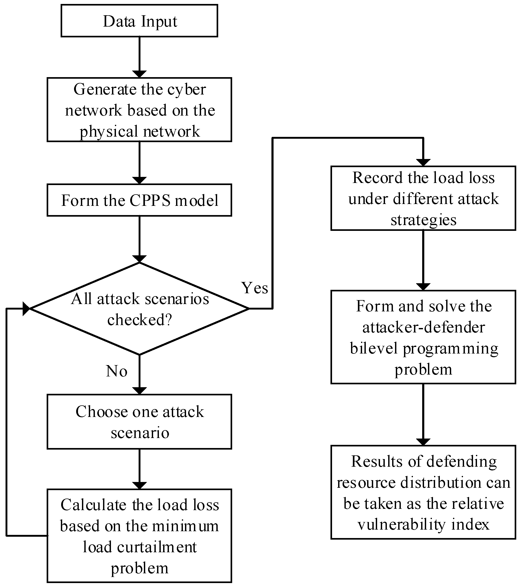
5.3. Vulnerability Assessment Procedure

The procedure of vulnerability assessment considering virtual CP-links is shown in Figure 3. It can be summarized as follows:
(1)
The CPPS model is formed. The P-nodes and PP-links of the CPPS model are formed, based on the power flow model. The C-nodes and CC-links are then added, based on the one-to-one mapping rule between the P-nodes and C-nodes, and between the PP-links and CC-links, as shown in Figure 2.
(2)
Choose one attack scenario of the attacker to successfully compromise the components (e.g., a PP-link/a PP-link and a C-node/a PP-link and two C-nodes), and calculate the total load loss as in Equations (1)–(7).
(3)
Check whether all attack scenarios have been enumerated. If yes, go to Step 4, otherwise go to Step 2.
(4)
Formulate the bi-level optimization problem as in Equations (12)–(21).
(5)
The optimal defending resource distribution on the PP-links and C-nodes can be solved. Based on the result, the vulnerability of different components can be illustrated.

6. Case Studies

The modified IEEE 14-bus system is utilized to illustrate the proposed method in this paper, as shown in Figure 4. This system includes 14 P-nodes and 20 PP-links. Some C-nodes are added, based on the rule that every P-node is mapped to a C-node. Note that the 5th C-node is chosen as the control center. Every PP-link is mapped to a CC-link, and the CC-links form the cyber network. The configuration of the IEEE test system is extracted from MATPOWER, a MATLAB package for solving power flow problems [31]. All the experiments are simulated in MATLAB 9.5.0 (The MathWorks, Inc, Natick, MA, USA) on a DELL PC running Windows 10 with a 3.0 GHz Core i7 processor (Intel, Santa Clara, CA, USA) and 8 GB memory (Samsung, Seoul, South Korea).
In order to consider the impacts of a cyber-physical coordinated attack, three cases are considered:
(1)
Case 1: only a PP-link is attacked, and the defender focuses on only defending PP-links;
(2)
Case 2: one PP-link and one C-node are attacked, and the defender aims to defend both PP-links and C-nodes;
(3)
Case 3: one PP-link and two C-nodes are attacked, as discussed previously; the defender also aims to defend both PP-links and C-nodes.
The branch power flow limit is set to be 1.3 times of the branch power flow in its initial state. After the attack, rearranging generator output is considered first. If this cannot settle the power flow off limit problem, load curtailment and line outage may be needed.
For the above three cases, up to one PP-link and two C-nodes may be compromised in each attack. In order to illustrate component vulnerability, the system loss is first calculated under the circumstance when there is no defense to attacks. That is, all components will fail once being attacked. The load loss is shown in Table 1. Among the attack actions in Table 1, PP, PP + C, PP + C + C represent Cases 1, 2, and 3 as mentioned above, respectively. The two columns with % symbols represent the extra load loss percentage of Case 2 over Case 1, and Case 3 over Case 1, respectively. Note that an attack against different C-nodes causes different results, and the results shown in Table 1 represent the worst cases among all possible scenarios.
It is obvious that an attack against different PP-links may lead to different load losses. Moreover, after a PP-link is compromised, the coordinated attack against the C-nodes is likely to cause a higher load loss. As explained in Section 3, the physical failures and cyber failures have an impact over another subsystem. As a matter of fact, in the simulation process, a C-node failure occasionally leads to communication interruption such that some physical components cannot be monitored or controlled, which causes the worse-case system load loss situation. In the worst case when the PP-link 1-5 is tripped, further attack against 2 C-nodes would cause up to 21.46% extra load loss.
Based on the knowledge of load loss under different attack actions, the defending resources are then distributed by solving the bi-level programming problem. The total amount of defending resources is set as 50% of the total number of vulnerable components. In this modified IEEE 14 bus system, there are 20 PP-links and 14 C-nodes vulnerable to malicious attacks from outsiders, and therefore we let Dp = 10 and Dc = 7. Distribution of defending resources for PP-links and C-nodes in Case 3 is shown in Table 2. The expected load loss after defending resources are distributed under different attack cases as shown in Table 3.
By comparing data between Table 3 and Table 1, it is obvious that the existence of defending resources decreases the expected load loss. A much more exciting result from Table 3 is that in the worst case (i.e. an attack on PP-link 1-5), the coordinated attack on two C-nodes only causes 3.7% extra loss from the original 21.46%. Meanwhile, other devastating attack results (e.g., attacks on PP-links 1–2 or 2–5) are reduced from 17.86% and 16.42% to 0.43%. These results show that with well-planned cyber defending resources distributed, the extra damage to the system caused by the attacker can be reduced to a minimum level. By defending the cyber components, the CPPS vulnerability can be significantly reduced.

7. Conclusions and Future Work

As a growing number of information and communication infrastructures are applied to a modern power system, the CPPS is formed and has drawn great attention of both researchers and industry. This paper investigates the interactions between physical components and cyber components in the CPPS, and proposes a CPPS interactive model framework. Then, the interactions are considered in the system load curtailment operation under malicious attacks on both physical and cyber components. Based on this, the game theory-based attacker–defender bi-level programming problem is formulated, and the component vulnerability is examined from solving the optimal defending resource distribution. The effectiveness of this model is demonstrated by the simulation results.
The future work includes incorporating more complicated components behaviors (e.g., transmission delay in CC-links) into the developed model and considering more detailed interactions among CP-links.

Author Contributions

K.C. proposed the methodological framework and mathematical model, and performed the simulations; F.W., C.-L.T., M.C., Z.Y., H.Z., and H.S. analyzed the results, reviewed the manuscript, and provided suggestions. All authors discussed the simulation results and agreed for submission.

Funding

This work is jointly supported by National Key Research and Development Program of China (2017YFB0902900), and China Southern Power Grid Key Project (No. GZHKJXM20160035).

Conflicts of Interest

The authors declare no conflict of interest.

Nomenclature

P-nodePhysical node
C-nodeCyber node
PP-linkPhysical-physical link
CC-linkCyber-cyber link
CP-linkCyber-physical link
LThe collection of load in the system
LaThe collection of controllable load in the system
LoffThe collection of uncontrollable load in the system
GThe collection of generators in the system
GaThe collection of controllable generators in the system
GoffThe collection of uncontrollable generators in the system
PLiThe power changed at load i (MW)
PGjThe power changed at generator j (MW)
P L i m The lower limit of load i (MW)
P L i M The upper limit of load i (MW)
P G j m The lower limit of generator j (MW)
P G j M The upper limit of generator j (MW)
PiThe real power at node i (MW)
PiThe change of real power at node i (MW)
ViThe voltage amplitude at node i (kV)
θijThe angle difference of branch ij (rad)
θijThe change of angle difference of branch ij (rad)
BijThe susceptance of branch ij in the bus admittance matrix (S)
NThe collection of all nodes in the system
nThe number of nodes in the system
dpThe defending resource distributed to PP-links
dcThe defending resource distributed to C-nodes
aA possible attack action
wThe attacker’s weight on different attack actions
waThe attacker’s weight on attack action a
RaThe total load curtailment when attack action a is launched (MW)
xaThe PP-link targeted by attack action a
y1aThe first C-node targeted by attack action a
y2aThe second C-node targeted by attack action a
p x a The probability of the PP-link xa successfully compromised by the attacker
p y 1 a The probability of the first C-node y1a successfully compromised by the attacker
p y 2 a The probability of the second C-node y2a successfully compromised by the attacker
R ( x a , y 1 a , y 2 a ) The load curtailment when components ( x a , y 1 a , y 2 a ) are successfully compromised by the attacker (MW)
R ( x a , y 1 a ) The load curtailment when components ( x a , y 1 a ) are successfully compromised by the attacker (MW)
R ( x a ,   y 2 a ) The load curtailment when components ( x a , y 2 a ) are successfully compromised by the attacker (MW)
R ( x a ) The load curtailment when components ( x a ) are successfully compromised by the attacker (MW)
βpThe failure coefficient of PP-links
βcThe failure coefficient of C-nodes
NPPThe number of PP-links in the system
NCThe number of C-nodes in the system
DpThe total defending resource for PP-links
DcThe total defending resource for C-nodes

References

  1. Kim, K.D.; Kumar, P.R. Cyber-physical systems: A perspective at the centennial. Proc. IEEE 2012, 100, 1287–1308. [Google Scholar]
  2. Mamo, X.; Mallet, S.; Coste, T.; Grenard, S. Distribution automation: The cornerstone for smart grid development strategy. In Proceedings of the IEEE Power & Energy Society General Meeting, Calgary, AB, Canada, 26–30 July 2009; pp. 1–6. [Google Scholar]
  3. Kirschen, D.; Bouffard, F. Keeping the lights on and the information flowing. IEEE Power Energy Mag. 2009, 7, 50–60. [Google Scholar] [CrossRef]
  4. Tram, H. Technical and operation considerations in using smart metering for outage management. In Proceedings of the IEEE PES Transmission and Distribution Conference and Exposition, Chicago, IL, USA, 21–24 April 2008; pp. 1–3. [Google Scholar]
  5. Liang, G.; Weller, S.R.; Zhao, J.; Luo, F.; Dong, Z.Y. The 2015 ukraine blackout: Implications for false data injection attacks. IEEE Trans. Power Syst. 2016, 32, 3317–3318. [Google Scholar] [CrossRef]
  6. Susuki, Y.; Koo, T.J.; Ebina, H.; Yamazaki, T.; Ochi, T.; Uemura, T.; Hikihara, T. A hybrid system approach to the analysis and design of power grid dynamic performance. Proc. IEEE 2012, 100, 225–239S. [Google Scholar] [CrossRef]
  7. Yampolskiy, M.; Horvath, P.; Koutsoukos, X.D.; Xue, Y.; Sztipanovits, J. Taxonomy for description of cross-domain attacks on CPS. In Proceedings of the 2nd ACM International Conference on High Confidence Networked Systems, Philadelphia, PA, USA, 9–11 April 2013; pp. 135–142. [Google Scholar]
  8. Yampolskiy, M.; Horváth, P.; Koutsoukos, X.D.; Xue, Y.; Sztipanovits, J. A language for describing attacks on cyber-physical systems. Int. J. Crit. Infrastruct. Prot. 2015, 8, 40–52. [Google Scholar] [CrossRef]
  9. Petnga, L.; Xu, H. Security of unmanned aerial vehicles: dynamic state estimation under cyber-physical attacks. In Proceedings of the 2016 International Conference on Unmanned Aircraft Systems (ICUAS), Arlington, VA, USA, 7–10 June 2016; pp. 811–819. [Google Scholar]
  10. Li, Y.; Shi, L.; Cheng, P.; Chen, J.; Quevedo, D.E. Jamming attacks on remote state estimation in cyber-physical systems: A game-theoretic approach. IEEE Trans. Autom. Control 2015, 60, 2831–2836. [Google Scholar] [CrossRef]
  11. Mo, Y.; Chabukswar, R.; Sinopoli, B. Detecting integrity attacks on SCADA systems. IEEE Trans. Control Syst. Technol. 2014, 22, 1396–1407. [Google Scholar]
  12. Mo, Y.; Sinopoli, B. Secure estimation in the presence of integrity attacks. IEEE Trans. Autom. Control 2015, 60, 1145–1151. [Google Scholar] [CrossRef]
  13. Fawzi, H.; Tabuada, P.; Diggavi, S. Secure estimation and control for cyber-physical systems under adversarial attacks. IEEE Trans. Autom. Control 2014, 59, 1454–1467. [Google Scholar] [CrossRef]
  14. Pasqualetti, F.; Carli, R.; Bullo, F. A distributed method for state estimation and false data detection in power networks. In Proceedings of the 2011 IEEE International Conference on Smart Grid Communications (SmartGridComm), Brussels, Belgium, 17–20 October 2011; pp. 469–474. [Google Scholar]
  15. Mo, Y.; Garone, E.; Casavola, A.; Sinopoli, B. False data injection attacks against state estimation in wireless sensor networks. In Proceedings of the 49th IEEE Conference on Decision and Control (CDC), Atlanta, GA, USA, 15–17 December 2010; pp. 5967–5972. [Google Scholar]
  16. Li, Y.; Quevedo, D.E.; Dey, S.; Shi, L. A game-theoretic approach to fake-acknowledgment attack on cyber-physical systems. IEEE Trans. Signal Inf. Proc. Netw. 2017, 3, 1–11. [Google Scholar] [CrossRef]
  17. Poisel, R. Modern Communications Jamming: Principles and Techniques; Artech House: Norwood, MA, USA, 2011. [Google Scholar]
  18. Zhang, H.; Cheng, P.; Shi, L.; Chen, J. Optimal DoS attack scheduling in wireless networked control system. IEEE Trans. Control Syst. Technol. 2016, 24, 843–852. [Google Scholar] [CrossRef]
  19. Zhang, H.; Cheng, P.; Shi, L.; Chen, J. Optimal denial-of-service attack scheduling with energy constraint. IEEE Trans. Autom. Control 2015, 60, 3023–3028. [Google Scholar] [CrossRef]
  20. Zhu, M.; Martínez, S. On the performance analysis of resilient networked control systems under replay attacks. IEEE Trans. Autom. Control 2014, 59, 804–808. [Google Scholar] [CrossRef]
  21. Deng, R.; Zhuang, P.; Liang, H. CCPA: coordinated cyber-physical attacks and countermeasures in smart grid. IEEE Trans. Smart Grid 2017, 8, 2420–2430. [Google Scholar] [CrossRef]
  22. Li, Z.; Shahidehpour, M.; Alabdulwahab, A.; Abusorrah, A. Bi-level model for analyzing coordinated cyber-physical attacks on power systems. IEEE Trans. Smart Grid 2016, 7, 2260–2272. [Google Scholar] [CrossRef]
  23. Soltan, S.; Yannakakis, M.; Zussman, G. Power grid state estimation following a joint cyber and physical attack. IEEE Trans. Control Netw. Syst. 2018, 5, 499–512. [Google Scholar] [CrossRef]
  24. Xin, S.; Guo, Q.; Sun, H.; Zhang, B.; Wang, J.; Chen, C. Cyber-physical modeling and cyber-contingency assessment of hierarchical control systems. IEEE Trans. Smart Grid 2015, 6, 2375–2385. [Google Scholar] [CrossRef]
  25. Ilic, M.D.; Xie, L.; Khan, U.A.; Moura, J.M. Modeling of future cyber-physical energy systems for distributed sensing and control. IEEE Trans. Syst. Man Cybern. Part A Syst. Hum. 2010, 40, 825–838. [Google Scholar] [CrossRef]
  26. Buldyrev, S.V.; Parshani, R.; Paul, G.; Stanley, H.E.; Havlin, S. Catastrophic cascade of failures in interdependent networks. Nature 2010, 464, 1025. [Google Scholar] [CrossRef]
  27. Vespignani, A. Complex networks: The fragility of interdependency. Nature 2010, 464, 984. [Google Scholar] [CrossRef]
  28. Falahati, B.; Fu, Y.; Wu, L. Reliability assessment of smart grid considering direct cyber-power interdependencies. IEEE Trans. Smart Grid 2012, 3, 1515–1524. [Google Scholar] [CrossRef]
  29. Falahati, B.; Fu, Y. Reliability assessment of smart grids considering indirect cyber-power interdependencies. IEEE Trans. Smart Grid 2014, 5, 1677–1685. [Google Scholar] [CrossRef]
  30. Bard, J.F. Practical Bi-Level Optimization: Algorithms and Applications; Springer Science & Business Media: Berlin, Germany, 2013. [Google Scholar]
  31. Zimmerman, R.D.; Murillo-Sánchez, C.E.; Thomas, R.J. MATPOWER: Steady-State Operations, Planning and Analysis Tools for Power Systems Research and Education. IEEE Trans. Power Syst. 2011, 26, 12–19. [Google Scholar] [CrossRef]
Figure 1. The node–link model in a Cyber-Physical Power System (CPPS).
Energies 12 03002 g001
Figure 2. Node–link relationships in a CPPS.
Energies 12 03002 g002
Figure 3. Flowchart of the CPPS vulnerability assessment procedure.
Energies 12 03002 g003
Figure 4. The modified IEEE 14-bus system.
Energies 12 03002 g004
Table 1. Load loss under different attack scenarios assuming no defense to attacks.
PP-LinkLoad Loss by Different Attack Actions (MW) and the Extra Percentage (%)
PP (Case 1)PP + C (Case 2)%PP + C + C (Case 3)%
1-214.508814.5088017.100317.86
1-55.40976.270115.96.570421.46
2-300000
2-472.299174.54613.1176.38615.65
2-521.252623.845412.2024.743216.42
3-400000
4-520.659221.60794.5922.815210.44
4-718.152818.22920.4218.26110.60
4-98.0468.19131.818.2382.39
5-66.35246.85637.937.1512.56
6-119.41619.416109.41610
6-127.25947.259407.25940
6-1329.32531.9769.0432.275510.06
7-828.07329.70595.8230.09187.19
8-929.0729.07210.007229.07530.018
9-106.55416.554106.55410
9-149.32289.322809.32280
10-112.73412.734102.73420.0048
12-1300000
13-145.7565.75605.7560
Table 2. Distributions of defending resources in Case 3.
PP-LinkDefending ResourceC-NodeDefending Resource
1-20.712610
1-5020.0001
2-3030
2-41.606640.8996
2-50.940150
3-4060
4-50.922270
4-70.844580
4-90.308191.9131
5-60.1133101.9394
6-110.4216110
6-120.2232120
6-131.1329131.0694
7-81.0954141.1781
8-91.113
9-100.1364
9-140.4145
10-110
12-130
13-140.0157
Table 3. Expected load loss after distributions of defensive resources.
PP-LinkLoad Loss by Different Attack (MW) and the Extra Percentage (%)
PP (Case 1)PP + C (Case 2)%PP + C + C (Case 3)%
1-25.6425.65490.235.66610.43
1-55.40975.55752.735.61073.72
2-300000
2-45.6425.65490.235.66610.43
2-55.6425.65490.235.66610.43
3-400000
4-55.6425.65490.235.66610.43
4-75.6425.65490.235.66610.43
4-95.6425.65490.235.66610.43
5-65.6425.65490.235.66610.43
6-115.6425.65490.235.66570.42
6-125.6425.65490.235.66570.42
6-135.6425.65490.235.66610.43
7-85.6425.65490.235.66610.43
8-95.6425.65490.235.66580.42
9-105.6425.65490.235.66560.42
9-145.6425.65490.235.66550.42
10-112.73412.734102.73420.0036
12-1300000
13-145.6425.65490.235.66570.42

