Abstract
The performance of vibration energy harvesters is usually restricted by their frequency bandwidth. The double-clamped beam with strong natural nonlinearity is a simple way that can effectively expand the frequency bandwidth of the vibration energy harvester. In this article, a nonlinear electromagnetic vibration energy harvester with monostable double-clamped beam was proposed. A systematic analysis was conducted and a distributed parameter analytical model was established. On this basis, the output performance was estimated by the analytical model. It was found that the nonlinearity of the double-clamped beam had little influence on the maximum output, while broadening the frequency bandwidth. In addition, the resonant frequency, the frequency bandwidth, and the maximum output all increased following the increase of excitation level. Furthermore, the resonant frequency varies with the load changes, due to the electromagnetic damping, so the maximum output power should be gained at its optimum load and frequency. To experimentally verify the established analytical model, an electromagnetic vibration energy harvester demonstrator was built. The prediction by the analytical model was confirmed by the experiment. As a result, the open-circuit voltage, the average power and the frequency bandwidth of the electromagnetic vibration energy harvester can reach up to 3.6 V, 1.78 mW, and 11 Hz, respectively, under only 1 G acceleration, which shows a prospect for the application of the electromagnetic vibration energy harvester based on a double-clamped beam.
1. Introduction
Harvesting ambient vibration energy and converting it to electrical power is an important way for the power supply of wireless sensor networks [1,2,3]. There are different kinds of ways to harvest vibration energy, such as piezoelectricity [4,5,6], electromagnetism [7,8,9], and triboelectricity [10,11]. Each way has its advantage and disadvantage. The piezoelectric energy harvester and the triboelectric energy harvester have their advantage of large voltage, but the disadvantage is that the output current gains only a few microamperes due, to the large internal resistance. On the other hand, the electromagnetic energy harvester can generate the current of hundreds or thousands of microamperes, but the voltage is only tens or hundreds of millivolts. Furthermore, because the output is up to the rate of change of magnetic flux, the electromagnetic energy harvester is more suitable for the application of a high frequency environment [12].
In general, vibration energy harvesters are usually based on linear resonance, which can only harvest energy in a very narrow frequency range near their resonant frequencies [13,14,15]. To solve this problem, various feasible methods have been proposed for broadening the frequency bandwidth, such as energy harvester arrays with different resonant frequencies [16,17,18], combined eigen-modes [19,20,21], active/passive frequency turning technology [22,23], and nonlinearity [24,25,26,27,28]. Energy harvester arrays can generate output at several frequency ranges, but the output should be gained at the expanse of a large volume and low power density. The way of combined eigen-modes is utilizing the resonance of multiple eigen-frequencies that are close to each other, but the disadvantage is the reduction of maximum output. Active/passive frequency turning technology is turning the resonant frequency to match the ambient vibration by a feedback current loop or varying mechanical properties, which may need external actuation and power supply. The nonlinear vibration energy harvester has been widely studied in recent years, due to its excellent frequency band expansion performance, which can be classified as a mono-stable and multi-stable system. Compared with other frequency band expansion methods, the nonlinear vibration energy harvester has the advantages of a simple structure and high efficiency of frequency band expansion.
The double-clamped beam structure has excellent nonlinearity due to the strong axial tension; thus, the vibration energy harvester with double-clamped beam can broaden the frequency bandwidth effectively. Marzencki et al. [29] proposed that the nonlinear effect of a double-clamped beam under harmonic excitation could be used to broaden the frequency bandwidth of a piezoelectric vibration energy harvester. Hajati and Kim [30] exploited an ultra-wide bandwidth MEMS piezoelectric energy harvester by using a double-clamped piezoelectric ceramic transducer (PZT) beam with a center proof mass, which provided a power bandwidth exceeding 50%. Masana and Daqaq [31,32] investigated the nonlinear behavior of double-clamped piezoelectric beam subjected to axial load. The article discussed and compared the energy harvesters operating in the mono-stable configuration by applying the axial load blow critical bucking force and the bi-stable configuration by applying the axial load above critical bucking force. The results indicated that the monostable configuration showed better performance under low acceleration. Although the nonlinearity of the piezoelectric vibration energy harvester based on double-clamped beam had been reported by some literature, the application of nonlinearity induced by a double-clamped beam on the electromagnetic vibration energy harvester is rarely mentioned. Furthermore, the nonlinearity of a double-clamped beam is usually qualitatively described through the Duffing equation or simulated by the finite element simulation of statics. There are few references to calculate the nonlinearity of a double-clamped beam by analytical method. Although Soy et al. [9] calculated the linear and nonlinear stiffness of a double-clamped beam based on FR4 by the static method, the results showed a large deviation compared with the finite element simulation. Moreover, resonance is essentially a phenomenon of modal amplification for specific structures; therefore, a distributed parameter model combined with modal analysis is more reasonable to analyze the nonlinearity and electrical output of a vibration energy harvester.
In this paper, a nonlinear electromagnetic vibration energy harvester (n-EVEH) with a mono-stable double-clamped beam was proposed and the distributed parameter model for the n-EVEH device was also established. On this basis, we calculated the modal deformation and natural frequencies and compared them with the finite element (FEM) simulation results. In addition, the magnetic flux gradient of multiturn coils was also calculated. As a result, the output performance was estimated by the established analytical model. To experimentally verify the established analytical model, a test platform for the n-EVEH device was built. The prediction by the analytical model was confirmed by the experimental results. With a specific designed coil, the electromagnetic vibration energy harvester can generate an average power up to 1.78 mW under 124 Hz, 1 G acceleration excitation, which shows a prospect for the power supply of a wireless sensor network. This work also shows a significance for the structure design and performance improvement of a nonlinear electromagnetic vibration energy harvester.
2. The Device Structure and Analytical Model
The structure of the energy harvester is illustrated in Figure 1a, which mainly consists of four parts: Polyethylene terephthalate (PET) film, magnets, copper coils, and aluminum shells. The parameters of the n-EVEH device are given in Table 1. The voltage of upper and lower copper coils has a completely opposite phase, which can be inversely connected in a series to obtain a higher voltage output. The shells were made of 6061 aluminum alloy. The PET film was clamped by four screws. The N35 Neodymium (NdFeB) magnets were fixed on the PET film by magnetic attraction. The magnets were polarized along the thickness direction. The overall dimension of the device is 62 mm × 29 mm × 24 mm.
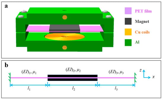
Figure 1.
(a) Schematic diagram and (b) vibration structure of the nonlinear electromagnetic vibration energy harvester (n-EVEH) based on a double-clamped beam.

Table 1.
Material and structural parameters of the n-EVEH device.
The vibration structure only consists of a double-clamped PET film and two pieces of magnet, which can be equivalent to a three-section Euler beam (Figure 1b). The modal deformation and natural frequencies can be obtained through modal analysis. The analytical calculation results can be gained from the undamped free vibration equation [9,35]:
where (EI)i, μi, xi, and hi represent the bending stiffness, the linear density, the coordinate, and the displacement of the ith section Euler beam, respectively, while t is the time. The method of separation of variables can be used to solve Equation (1) by separating the spatial and temporal functions as . Thus, we can obtain
The boundary conditions are
where li is the length of each section beam. By substituting Equation (3) into the boundary conditions, and considering the orthogonal normalization condition
where δrs is the Dirac function, we can obtain
where fhr, ϕr, pr represents the rth natural frequency, the rth modal deformation, and the rth modal, respectively. The displacement hi can be written as
The equation of forced vibration for the energy harvester under harmonic excitation is
where chi is the damping of each section beam, a is the excitation acceleration, and ω is the excitation angular frequency.
is the axial tension during vibration, which is the source of nonlinearity of the double-clamped beam, where Eu, b, tu is the Young’s modulus, the half width, and the thickness of the PET film, respectively. By substituting Equation (7) into the forced vibration Equation (8), we can obtain the modal function of vibration:
where ζhr = ζmhr + ζemhr is the damping ratio, and ζmhr and ζemhr are the mechanical damping ratio and electromagnetic damping ratio, respectively. The nonlinear coefficient εr is given by
The pr, ωhr2 and εr can also be seen as generalized displacement, generalized linear stiffness, and generalized nonlinear stiffness, respectively. It is obvious that Equation (10) is the Duffing equation and the relationship between the modal amplitude and frequency of main resonance can be solved as
When the magnets are located at the middle of the PET film, the relationship between the velocity amplitude of magnets and non-dimensional frequency near the first natural frequency is
where
V is the velocity amplitude of magnets, and Ω = ω/ωh1 is the non-dimensional frequency.
The equivalent circuit of the n-EVEH is shown in Figure 2, where Rc is the resistance of coils, Rl is the load resistance, and LC is the inductance of coils, which can be neglected in the low vibration frequency (lower than 1 kHz) [36]. The load voltage of the electromagnetic vibration energy harvester can be written as
where z is the coordinate, Kz is the magnetic flux gradient in the z direction of coils, which is known as the electromagnetic coupling coefficient, Up is the peak voltage, and the root–mean–square (RMS) voltage is . The current can be gained by and the average power can be obtained by
The electromagnetic damping ratio of the first modal can be given by [8,36]
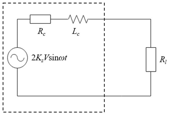
Figure 2.
The equivalent circuit of the n-EVEH.
3. Result and Discussion
Modal analysis is the foundation of vibration analysis. Similar to the analytical model, the ANSYS modal analysis also neglects nonlinearity, so the FEM simulation (ANSYS workbench) can be used for the verification of modal analysis by the analytical model. By setting the mesh size as fine, the modal deformation and natural frequencies were obtained by the FEM simulation. Figure 3 and Table 2 show the modal deformation and the natural frequencies by the FEM simulation and the derived analytical model, respectively. The second modal is shown because the vibration of energy harvester near the first natural frequency may be affected by the adjacent modal. We can see that the results by the derived analytical model and the FEM simulation are consistent, which demonstrates that the derived analytical model is reliable. The error of the first natural frequency between analytical model and the FEM result is 5.68%. The error considered mainly comes from the constraint of vibrational degree of freedom by the derived analytical model. In addition, the first modal deformation is symmetric about the perpendicular bisector (seen in Figure 3a,c) and the vibration of magnets is consistent along the axial direction, so the Equation (13) should be reasonable. The second modal deformation is antisymmetric about the middle of the magnets (seen in Figure 3b,c), the integral on the right-hand side of Equation (9) is zero; thus, the output performance of the double-clamped beam will not be influenced by the second modal under the excitation of base.
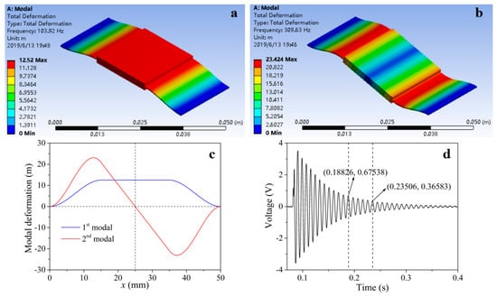
Figure 3.
(a) The first and (b) the second modal deformation of the n-EVEH by the finite element (FEM) simulation. (c) The first and the second modal deformation of the n-EVEH by the derived analytical model. (d) The open-circuit voltage waveform of free vibration.

Table 2.
The first and the second natural frequencies by the FEM simulation and the derived analytical model.
The first natural frequency is usually equal to the frequency of free vibration, so it can be measured by the free vibration method. Figure 3d shows the open-circuit voltage waveform of free vibration, the energy harvester connected directly to the oscilloscope to obtain the open-circuit voltage waveform (the resistance of the oscilloscope is about 1 MΩ). For a nonlinear system, the frequency of free vibration is easily affected by the amplitude, so we calculated the first natural frequency in a region of small voltage amplitude. The first natural frequency is 106.8 Hz, which is close to the results by the analytical model and the FEM simulation. In the meantime, the mechanic damping ratio can also be calculated though the open-circuit voltage waveform of free vibration, and the result is 0.0195. All of the calculation methods are shown below.
The first natural frequency can be calculated by
where t1 and t5 are 0.18826 s and 0.23506 s, representing the time of the first and the fifth point in time, respectively. The mechanic damping ratio can be given by
where U1 is 0.67538 V, representing the peak voltage of the first point in time, and U5 is 0.36583 V, representing the peak voltage of the fifth point in time.
The magnetic flux gradient is an important factor affecting the output performance of the n-EVEH device. The magnetic current density J can be obtained by measuring the magnetic induction intensity Bz on the surface center position of the magnet, which is 482 mT (measured by a gauss meter), so the magnetic current density can be calculated as 8.55 × 10⁵ A/m2 through Equation (S2). Figure 4a shows the relationship between the magnetic field gradient and coordinate φ with a different coordinate r in polar coordinates (the distance between magnets and the polar coordinate plane is 7 mm), which can be calculated by Equations (S1) and (S2). The magnetic field gradient decreases with the increase of coordinate r, which illustrates that the farther away from the center of magnets, the smaller the magnetic field gradient. In addition, although the magnetic field gradient varies with the coordinate φ, which is symmetric about the 1/8 polar coordinate plane, it demonstrated that the mesh generation of the 1/8 coil plane is reasonable. Consequently, we can reduce the amount of calculation without reducing the accuracy by this method. Figure 4b shows the magnetic flux gradient of a single-turn coil with different distances between magnets and coil relevant to the radius of the coil (by Equation (S4)). The results show that the smaller the distance between magnets and coil, the bigger the magnetic flux gradient is. In the meantime, the magnetic flux gradient of the coil increases first and then decreases with the increase of the coil radius, and reaches a maximum value at a certain coil radius. Thus, the magnetic flux gradients of the outer coils are even smaller than the inner coils for the multi-turn coils with a large size. In this paper, when the coil with the spacing of 4 mm, 7 mm, and 10 mm reaches the maximum flux gradient, the corresponding radius is 12 mm, 13 mm, and 14.3 mm, respectively. Thus, setting the external diameter of coils as 27 mm is reasonable. Finally, assuming the coils were dense array, the magnetic flux gradient of 5308 turn coils can be calculated through the Equation (S5), which is shown in Figure S1. The magnetic flux gradient is 6.47 Wb/m when n = 20.
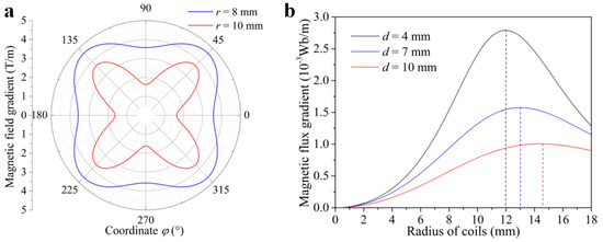
Figure 4.
(a) The relationship between the magnetic field gradient and the coordinate φ in polar coordinates. (b) The relationship between the magnetic flux gradient of a single-turn coil and the radius of the coil.
According to the analytical model, the open-circuit voltage, the load voltage, and the load power of the n-EVEH can be estimated. The prediction of output performance by the analytical model is shown in Figure 5. Figure 5a shows the root–mean–square (RMS) open-circuit voltage under 1 G acceleration (1 G = 9.81 m/s2). Because of the multi-value character of the Duffing equation, the output of the n-EVEH device shows a “jump” at the resonant frequency, and there are two stable branches (the high-energy branch and the low-energy branch) within a certain frequency range. The high energy branch usually has a high output and wide frequency bandwidth, which is the principle to expand the frequency bandwidth of the n-EVEH device. In the meanwhile, the results show that the n-EVEH can generate a maximum voltage of 3.8 V at its resonant frequency of 129 Hz, and the 3 dB frequency bandwidth is 13 Hz. The black curve in Figure 5a presents the linear result ignoring the nonlinear coefficient, which can indicate that the nonlinear effect of a double-clamped beam has little influence on the maximum output, while broadening the frequency bandwidth. Figure 5b shows the influence of different acceleration levels on the RMS open-circuit voltage of the n-EVEH. It indicates that the resonant frequency, the maximum output, and the frequency bandwidth all increase following the increase of the acceleration levels. As a result, the resonant frequency, the maximum voltage, and the frequency bandwidth are 109 Hz, 1.9 V, and 7 Hz, respectively, under the acceleration of 0.5g. When the acceleration is up to 1.5g, the resonant frequency, the maximum voltage, and the frequency bandwidth can reach to 147 Hz, 5.6 V, and 18 Hz.

Figure 5.
The prediction by the analytical model. The root–mean–square (RMS) open-circuit voltage under (a) 1 G acceleration and (b) different acceleration levels. (c) The RMS load voltage and (d) the average power under 1 G acceleration.
The relationship between the RMS load voltage and frequency under 1 G acceleration is shown in Figure 5c. Because the electromagnetic damping ratio decreases with the increase of load resistance, the resonant frequency improves following the increase of load resistance. According to Equation (16), the average power can be calculated, which is shown in Figure 5d. The n-EVEH can output a maximum power of 2.08 mW with the optimum load resistance of 1.5 kΩ under the resonant frequency of 122 Hz. The prediction by the analytical model shows that the n-EVEH has a good output performance.
In order to verify the analytical prediction, an experimental platform was built, which is shown in Figure S2. The n-EVEH device was driven by an electromagnetic (EM) shaker (YMC (Yangzhou, China) VT-500), which was connected to a signal generator (YMC 9200) and a power amplifier (YMC LA-800) for controlling the frequency and the amplitude of the shaker, respectively. The vibration signal was measured by an accelerometer (YMC 271A01) mounted on the shaker. The signal from the accelerometer was transmitted by a charge amplifier (YMC 8102) and collected by a PC-based data acquisition system (YMC 9004). The output voltage signal was measured and displayed on an oscilloscope (KESIGHT InfiniiVision DSO-X 2012A).
The experimental results of the open-circuit voltage are shown in Figure 6. Figure 6a shows the relationship between the RMS open-circuit voltage and excitation frequency under 1 G acceleration. The voltage of up-sweeping and down-sweeping was quite different, which respectively corresponded to the output of high-energy branch and low-energy branch by the analytical prediction, while the wideband effect was caused by its high-energy branch. The results show that the n-EVEH device can output a maximum RMS open-circuit voltage of 3.6 V at the resonant frequency of 128 Hz, while the 3 dB frequency bandwidth was 11 Hz. Figure 6b shows the relationship between the RMS open-circuit voltage and frequency under different acceleration levels. The resonant frequency, the maximum voltage, and the frequency bandwidth of the n-EVEH device under the acceleration of 0.5 G were 115 Hz, 1.9 V, and 7 Hz, respectively. All of them increased with the acceleration levels, which was in agreement with the analytical prediction. As a result, the resonant frequency, the maximum voltage, and the frequency bandwidth can reach to 135 Hz, 4.7 V, and 13 Hz under the acceleration of 1.5 G. Table 3 shows the comparation of the analytical prediction and the experimental results. The deviation between analytical prediction and experimental results increases with the increase of acceleration levels, which can be considered to mainly come from the enhancement of material nonlinearity under large deformation. Therefore, the analytical model is more suitable to predict the output under low acceleration levels.
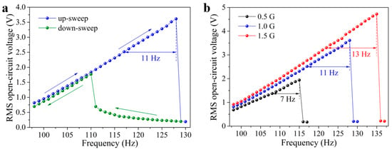
Figure 6.
The experimental results of the RMS open-circuit voltage. The voltage as a function of frequency under (a) 1 G acceleration and (b) different acceleration levels.

Table 3.
The comparation between the analytical prediction and the experimental results.
The experimental results of the RMS load voltage under 1 G acceleration are shown in Figure 7a. We can see that the higher the load resistance, the higher the load voltage was. In addition, the resonant frequency improved with the increase of the load resistance, which was consistent with the analytical prediction. The load voltage waveform and the current waveform is shown in Figure S3, the energy harvester can generate a steady output. Figure 7b shows the average power of the n-EVEH under different frequencies and load resistances, which can be calculated by Equation (16). The energy harvester can generate a maximum average power of 1.78 mW with the optimum load resistance of 2 kΩ under the resonant frequency of 124 Hz. The error of the maximum power between the analytical prediction and the experimental result is 16.85%. This deviation is acceptable; thus, the derived analytical model can be used for the output prediction of the n-EVEH device reasonably. Finally, the high output and the large frequency bandwidth show that the n-EVEH with double-clamped beam has potential application prospects for the power supply of a wireless sensor network node.
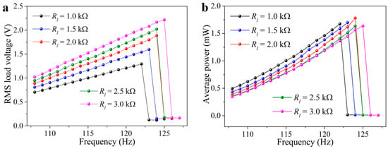
Figure 7.
(a) The RMS load voltage and (b) the average power as a function of frequency with different load resistance.
4. Conclusions
In this paper, the strong nonlinear effect of the double-clamped beam under harmonic excitation was proved by the analytical model and the experimental results. It was a simple and effective method to increase the frequency bandwidth of the electromagnetic energy harvester. Both the modal deformation and the natural frequencies obtained through the analytical model showed a good agreement with the FEM simulation results. It was found that the nonlinearity of the double-clamped beam has a neglectable influence on the maximum output, while broadening the frequency bandwidth. The resonant frequency, the maximum output, and the frequency bandwidth all increased with the increase of acceleration levels propositionally. The output performance predicted by the analytical model was verified by the experimental results. As a result, the open-circuit voltage, the average power, and the frequency bandwidth of the n-EVEH devices can reach to 3.6 V, 1.78 mW, and 11 Hz, respectively, under the acceleration of 1 G. The n-EVEH in this paper has a high output and large frequency bandwidth. It has the potential application prospect for the power supply of wireless sensor networks. This work can also provide reference for the theoretical analysis of other dynamic devices.
Supplementary Materials
The following are available online at https://www.mdpi.com/1996-1073/12/14/2710/s1, Figure S1: The relationship between the magnetic flux gradient of coils and n, Figure S2: (a) Experimental setup, (b) The energy harvester prototype, which can power an LED under the excitation of 1 G acceleration, 120 Hz, Figure S3: (a) The load voltage waveform and (b) the current waveform of the n-EVEH device under the excitation of 1 G acceleration, 124 Hz (the load resistance is 2 kΩ), the energy harvester can generate a steady output.
Author Contributions
Z.L. carried out the analytical model and designed the experiments; Q.W. and Z.W. provided funding and experimental facilities; Z.L. wrote the paper; Q.W., X.H. and Z.W. revised the paper.
Funding
This work was supported by the National Natural Science Foundation of China (61604023).
Conflicts of Interest
The authors declare no conflict of interest.
References
- Zhang, W.Y.; Dong, Y.; Tan, Y.S.; Zhang, M.; Qian, X.; Wang, X.H. Electric Power Self-Supply Module for WSN Sensor Node Based on MEMS Vibration Energy Harvester. Micromachines 2018, 9, 161. [Google Scholar] [CrossRef] [PubMed]
- Challa, V.R.; Prasad, M.G.; Fisher, F.T. Towards an autonomous self-tuning vibration energy harvesting device for wireless sensor network applications. Smart Mater. Struct. 2011, 20, 25004–25011. [Google Scholar] [CrossRef]
- Qiu, J.; Chen, H.J.; Wen, Y.M.; Li, P. Magnetoelectric and electromagnetic composite vibration energy harvester for wireless sensor networks. J. Appl. Phys. 2015, 117, 17A331. [Google Scholar] [CrossRef]
- Kim, S.; Towfeeq, I.; Dong, Y.C.; Gorman, S.; Rao, A.M.; Koley, G. P(VDF-TrFE) Film on PDMS Substrate for Energy Harvesting Applications. Appl. Sci. 2018, 8, 213. [Google Scholar] [CrossRef]
- Orrego, S.; Shoele, K.; Ruas, A.; Doran, K.; Caggiano, B.; Mittal, R.; Kang, S.H. Harvesting ambient wind energy with an inverted piezoelectric flag. Appl. Energy 2017, 194, 212–222. [Google Scholar] [CrossRef]
- Han, M.; Zhang, X.S.; Meng, B.; Liu, W.; Tang, W.; Sun, X.M.; Wang, W.; Zhang, H.X. r-Shaped Hybrid Nanogenerator with Enhanced Piezoelectricity. ACS Nano. 2013, 7, 8554–8560. [Google Scholar] [CrossRef] [PubMed]
- Nammari, A.; Caskey, L.; Negrete, J.; Bardaweel, H. Fabrication and characterization of non-resonant magneto-mechanical low-frequency vibration energy harvester. Mech. Syst. Singal Process. 2018, 102, 298–312. [Google Scholar] [CrossRef]
- Mallick, D.; Amann, A.; Roy, S. A nonlinear stretching based electromagnetic energy harvester on FR4 for wideband operation. Smart Mater. Struct. 2011, 20, 25004–25011. [Google Scholar] [CrossRef]
- Foong, F.M.; Thein, C.K.; Ooi, B.L.; Yurchenko, D. Increased power output of an electromagnetic vibration energy harvester through anti-phase resonance. Mech. Syst. Singal Process. 2019, 116, 129–145. [Google Scholar] [CrossRef]
- Wang, W.C.; Xu, J.C.; Zheng, H.W.; Chen, F.Q.; Jenkins, K.; Wu, Y.H.; Wang, H.Y.; Zhang, W.F.; Yang, R.S. A spring-assisted hybrid triboelectric–electromagnetic nanogenerator for harvesting low-frequency vibration energy and creating a self-powered security system. Nanoscale 2018, 10, 14747–14754. [Google Scholar] [CrossRef] [PubMed]
- He, J.; Wen, T.; Qian, S.; Zhang, Z.X.; Tian, Z.M.; Zhu, J.; Mu, J.L.; Hou, X.J.; Geng, W.P.; Cho, J.D.; et al. Triboelectric-piezoelectric-electromagnetic hybrid nanogenerator for high-efficient vibration energy harvesting and self-powered wireless monitoring system. Nano Energy 2018, 43, 326–339. [Google Scholar] [CrossRef]
- He, X.M.; Wen, Q.; Sun, Y.F.; Wen, Z.Y. A Low-Frequency Piezoelectric-Electromagnetic-Triboelectric Hybrid Broadband Vibration Energy Harvester. Nano Energy 2017, 40, 300–307. [Google Scholar] [CrossRef]
- Twiefel, J.; Westermann, H. Survey on broadband techniques for vibration energy harvesting. J. Intell. Mater. Syst. Struct. 2013, 24, 1291–1302. [Google Scholar] [CrossRef]
- Wei, C.F.; Jing, X.J. A comprehensive review on vibration energy harvesting: Modelling and realization. Renew. Sust. Energy Rev. 2017, 74, 1–18. [Google Scholar] [CrossRef]
- Liu, H.C.; Zhong, J.W.; Lee, C.K.; Lee, S.W.; Lin, L.W. A comprehensive review on piezoelectric energy harvesting technology: Materials, mechanisms, and applications. Appl. Phys. Rev. 2018, 5, 041306. [Google Scholar] [CrossRef]
- Zhao, X.F.; Li, S.; Ai, C.P.; Liu, H.M.; Wen, D.Z. Fabrication and Characterization of the Li-Doped ZnO Thin Films Piezoelectric Energy Harvester with Multi-Resonant Frequencies. Micromachines 2019, 10, 212. [Google Scholar] [CrossRef]
- Wang, W.; Huang, R.J.; Huang, C.J.; Li, L.F. Energy harvester array using piezoelectric circular diaphragm for rail vibration. Acta. Mech. Sinica 2014, 104, 012002. [Google Scholar] [CrossRef]
- Xiao, Z.; Yang, T.Q.; Dong, Y.; Wang, X.C. Energy harvester array using piezoelectric circular diaphragm for broaden vibration. Appl. Phys. Lett. 2014, 104, 223904. [Google Scholar] [CrossRef]
- Vyas, A.; Staaf, H.; Rusu, C.; Ebefor, T.; Liljholm, J.D.; Simith, A.; Lundgeren, P.; Enoksson, P. A Micromachined Coupled-Cantilever for Piezoelectric Energy Harvesters. Micromachines 2018, 9, 252. [Google Scholar] [CrossRef]
- Song, H.; Kumar, P.; Sriramdas, R.; Lee, H.; Sharpes, N.; Kang, M.; Maurya, D.; Sanghadasa, M.; Kang, H.W.; Ryu, J.; et al. Broadband dual phase energy harvester: Vibration and magnetic field. Appl. Energy 2018, 225, 1132–1142. [Google Scholar]
- El-Hebeary, M.M.R.; Arafa, M.H.; Megahed, S.M. Modeling and experimental verification of multi-modal vibration energy harvesting from plate structures. Sens. Actuat. A Phys. 2013, 193, 35–47. [Google Scholar] [CrossRef]
- Eichhorn, C.; Tchagsim, R.; Wilhelm, N.; Woias, P. A smart and self-sufficient frequency tunable vibration energy harvester. J. Micromech. Microeng. 2011, 21, 104003. [Google Scholar] [CrossRef]
- Gu, L.; Livermore, C. Compact passively self-tuning energy harvesting for rotating applications. Smart Mater. Struct. 2012, 21, 015002. [Google Scholar] [CrossRef]
- Mann, B.P.; Sims, N.D. Energy harvesting from the nonlinear oscillations of magnetic levitation. J. Sound Vib. 2009, 319, 515–530. [Google Scholar] [CrossRef]
- Zhou, S.X.; Cao, J.Y.; Lin, J. Analytical analysis and experimental verification for improving energy harvesting performance of nonlinear monostable energy harvesters. Nonlinear Dynam. 2016, 86, 1599–1611. [Google Scholar] [CrossRef]
- Lin, Z.M.; Yang, J.; Zhao, J.X.; Zhao, N.; Liu, J.; Wen, Y.M.; Li, P. Enhanced broadband vibration energy harvesting using a multimodal nonlinear magnetoelectric converter. J. Elctron. Mater. 2016, 45, 3554–3561. [Google Scholar] [CrossRef]
- Xiong, L.Y.; Tang, L.H.; Liu, K.F.; Mace, B.R. Broadband piezoelectric vibration energy harvesting using a nonlinear energy sink[J]. J. Phys. D Appl. Phys. 2018, 51, 185502. [Google Scholar] [CrossRef]
- Cao, J.Y.; Zhou, S.X.; Wang, W.; Lin, J. Influence of potential well depth on nonlinear tristable energy harvesting. Appl. Phys. Lett. 2015, 106, 173903. [Google Scholar] [CrossRef]
- Marzencki, M.; Defosseux, M.; Basrour, S. MEMS vibration energy harvesting devices with passive resonance frequency adaptation capability. J. Microelectromech. Syst. 2010, 18, 1444–1453. [Google Scholar] [CrossRef]
- Hajati, A.; Kim, S.G. Ultra-wide bandwidth piezoelectric energy harvesting. Appl. Phys. Lett. 2011, 99, 083105. [Google Scholar] [CrossRef]
- Masana, R.; Daqaq, F.M. Relative performance of a vibratory energy harvester in mono-and bi-stable potentials. J. Sound Vib. 2011, 330, 6036–6052. [Google Scholar] [CrossRef]
- Masana, R.; Daqaq, F.M. Response of duffing-type harvesters to band-limited noise. J. Sound Vib. 2013, 332, 6755–6767. [Google Scholar] [CrossRef]
- Pan, C.T.; Liu, Z.H.; Chen, Y.C.; Liu, C.F. Design and fabrication of flexible piezo-microgenerator by depositing ZnO thin films on PET substrates. Sens. Actuat. A-phys. 2010, 159, 96–104. [Google Scholar] [CrossRef]
- Pan, C.T.; Liu, Z.H.; Chen, Y.C. Study of broad bandwidth vibrational energy harvesting system with optimum thickness of PET substrate. Curr. Appl. Phys. 2012, 12, 684–696. [Google Scholar] [CrossRef]
- Chen, Y.; Mu, X.J.; Wang, T.; Ren, W.W.; Yang, Y.; Wang, Z.L.; Sun, C.L.; Gu, A.Y.D. Flutter Phenomenon in Flow Driven Energy Harvester - A Unified Theoretical Model for “Stiff”and “Flexible” Materials. Sci. Rep. 2016, 6, 35180. [Google Scholar] [CrossRef] [PubMed]
- Li, P.; Gao, S.Q.; Niu, S.H.; Liu, H.P.; Cai, H.T. An analysis of the coupling effect for a hybrid piezoelectric and electromagnetic energy harvester. Smart Mater. Struct. 2014, 23, 065016. [Google Scholar] [CrossRef]
© 2019 by the authors. Licensee MDPI, Basel, Switzerland. This article is an open access article distributed under the terms and conditions of the Creative Commons Attribution (CC BY) license (http://creativecommons.org/licenses/by/4.0/).