Article

A Firefly Algorithm Optimization-Based Equivalent Consumption Minimization Strategy for Fuel Cell Hybrid Light Rail Vehicle

1
State Key Laboratory of Traction Power, Southwest Jiaotong University, Chengdu 610031, China
2
School of Information Science and Technology, Southwest Jiaotong University, Chengdu 611756, China
3
Key Laboratory of Fluid and Power Machinery, Ministry of Education, Xihua University, Chengdu 610039, China
4
Key Laboratory of Automobile Measurement and Control & Safety, School of Automobile & Transportation, Xihua University, Chengdu 610039, China
5
College of Electrical and Information Engineering, Southwest Minzu University, Chengdu 610041, China
*
Author to whom correspondence should be addressed.
Energies 2019, 12(14), 2665; https://doi.org/10.3390/en12142665
Submission received: 3 June 2019 / Revised: 29 June 2019 / Accepted: 9 July 2019 / Published: 11 July 2019
(This article belongs to the Special Issue Optimal Control of Hybrid Systems and Renewable Energies)

Abstract

:
To coordinate multiple power sources properly, this paper presents an optimal control strategy for a fuel cell/battery/supercapacitor light rail vehicle. The proposed strategy, which uses the firefly algorithm to optimize the equivalent consumption minimization strategy, improves the drawback that the conventional equivalent consumption minimization strategy takes insufficient account of the global performance for the vehicle. Moreover, the strategy considers the difference between the two sets of optimized variables. The optimization objective is to minimize the daily operating cost of the vehicle, which includes the total fuel consumption, initial investment, and cycling costs of power sources. The selected case study is a 100% low-floor light rail vehicle. The advantages of the proposed strategy are investigated by comparison with the operating mode control, firefly algorithm-based operating mode control, and equivalent consumption minimization strategy. In contrast to other methods, the proposed strategy shows cost reductions of up to 39.62% (from operating mode control), 18.28% (from firefly algorithm-based operating mode control), and 13.81% (from equivalent consumption minimization strategy). In addition, the proposed strategy can reduce fuel consumption and increase the efficiency of the fuel cell system.

1. Introduction

With the environmental deterioration and energy crisis, developing green energy and new energy vehicles has become the consensus of government and public [1,2,3]. Compared with the small-power new energy vehicles like the plug-in hybrid vehicles and hybrid electric vehicles, the hybrid light rail vehicles are more suitable for urban public transportation, due to its high-power level and large-capacity.
As typical green energy, proton exchange membrane (PEM) fuel cell (FC) is suitable for the vehicle [4,5,6]. Proton exchange membrane fuel cell (PEMFC) has many advantages such as high reliability and efficiency, however, its dynamic response is slow. Designers often add an energy storage system (ESS) to assist the PEMFC system. The ESS can provide the extra energy, store the regenerative energy, and extend the cruising range [7].
The ESS often contains a battery (BAT) pack and/or a supercapacitor (SC) pack [8]. According to the different ESS, the PEMFC hybrid system can be divided into three types: (1) “PEMFC + BAT” [9], (2) “PEMFC + SC” [10], (3) “PEMFC + BAT + SC” [11]. Compared with the other two combinations, the optimized “PEMFC + BAT + SC” hybrid vehicle has the best fuel economy [12]. A 100% low-floor light rail vehicle (LF-LRV) is powered by “PEMFC + BAT + SC” hybrid system [13]. As the primary power source of the LF-LRV, the PEMFC provides the average power demand. Furthermore, the SC supplement the power during acceleration, because of its high specific power. As the second power compensation, the battery improves the dynamic performance of the whole hybrid system. Besides, the battery and SC can absorb braking energy [14].
Due to the introduction of ESS, there are multiple power sources in the hybrid system. The power control strategy is used to split the power demands among the power sources and meet the load power. The strategy is mainly divided into two types: rule-based and optimization-based [15]. The rules of the rule-based strategy can be made by power source characteristics. Ahmadi et al. [16] proposed an operating mode control (OMC) for the FC hybrid vehicle, and subsequently used the genetic algorithm (GA) to optimize the OMC. Caux et al. [17] implemented GA to optimize the fuzzy logic strategy and developed an online fuzzy logic strategy for the FC hybrid vehicle. Other examples of the rule-based strategy include: power follower strategy [18], model predictive control [19], sliding mode control [20], and so on. The rule-based strategy has strong applicability; however, its control performance depends on the experience of designers.
Different from the rule-based strategy, the optimization-based strategy needs to define an optimization objective and use optimization methods to obtain the control parameters or control law. By the length of time horizon, the optimization-based strategy consists of the global optimization strategy (GO) and instantaneous optimization strategy (IO) [21]. The GO can obtain the global optimum solution for the driving cycle. Hu et al. [22] and Xu et al. [23] applied the dynamic programming to a FC hybrid vehicle, respectively, and achieved good results. However, the main insufficiency of dynamic programming is the curse of dimensionality, and this limits its application in complex systems. Another example of GO is based on the meta-heuristic algorithms, such as GA and particle swarm optimization (PSO). Li et al. [24] used the GA to optimize the control strategy for the hybrid tramway, and fuel economy is improved. Olivier et al. [25] utilized PSO to optimize five driving parameters for the FC vehicle, in order to maximize vehicle performance. Zhang et al. [26] used the multi-population GA and the artificial fish swarm algorithm to reduce the operating costs of the high-power hybrid vehicle. GO can obtain good global performance, however, these methods are hard to real-time apply due to the heavy computation load.
Instantaneous optimization methods can obtain the control command in real time. As one of the typical IO, equivalent consumption minimization strategy (ECMS) is widely used in the small and medium power vehicles [27,28,29] because of its excellent instantaneous performance, but less used in the high-power light rail vehicle. Torreglosa et al. [30] developed a control method based on ECMS and improved the hydrogen consumption for an FC/battery light rail vehicle. Hong et al. [3] presented a method to introduce a dynamic power factor to ECMS for an FC/battery locomotive, in order to achieve less fuel consumption and high efficiency of the system. Zhang et al. [31] improved the fixed balance coefficient of conventional ECMS and presented a control strategy based on the hybrid dynamic degree for an FC/battery light rail vehicle.
The ECMS has been verified to effectively reduce fuel consumption for the “PEMFC + BAT” vehicle. However, the strategies cannot be used directly in the “PEMFC + BAT + SC” vehicle, as its solving process only considers FC and battery. To solve this problem, Zhang et al. [21] and Garcia et al. [32] used the SC to compensate the gap of load power that the FC and battery cannot meet, and developed the ECMS for FC/battery/SC light rail vehicle respectively. Yan et al. [33] proposed an equivalent energy consumption strategy for FC/SC light rail vehicle, and aims to minimize energy consumption in multiple modes. Nevertheless, the ECMS mentioned before cannot obtain the global optimal solution because of its aim to minimize instantaneous fuel/energy consumption. In fact, the global optimal solution is useful for the further decrease of the consumption of the light rail vehicle. Moreover, the optimization objective of ECMS only considers fuel/energy consumption. Actually, some other factors such as the total fuel consumption, sizing, and lifecycle of power sources, are also important for the overall evaluation of the operating cost of the vehicle.
In order to mitigate the problems mentioned above, this paper presents an optimal control strategy for the PEMFC/battery/SC light rail vehicle. The strategy uses the firefly algorithm (FA) to optimize the ECMS, and the aim is to obtain the global optimal solution. The optimization objective includes the total fuel consumption cost, initial investment, and replacement cost of power sources. The selected case study is a 100% low-floor light rail vehicle. The paper is structured as follows. In Section 2, the model of the vehicle is introduced. In Section 3, an improved ECMS combined conventional ECMS with OMC is designed. In Section 4, the FA is introduced. Subsequently, the optimization objective is defined. Based on this objective, an optimal control strategy integrates FA and ECMS is developed at last. The results are discussed in Section 5. In Section 6, the conclusions are summarized.

2. Vehicle Modeling

A 100% LF-LRV is assembled by the CRRC Tangshan Co. Ltd. and Southwest Jiaotong University [34], as shown in Figure 1a. The vehicle includes two motor units, powered by the PEMFC system, SC pack, and battery pack [13]. The PEMFC system is the primary power source that provides the average traction power. Besides, the SC pack and battery pack are utilized for the ESS to help the PEMFC system during the vehicle cruise and acceleration and can absorb energy during braking. The diagram of the hybrid system’s power flow is shown in Figure 1b.
In order to test the performance of the proposed strategy, a backward/forward LF-LRV model is established. The model consists of eight blocks: the driving cycle, train longitudinal dynamics, wheel dynamics, transmission system, motor, DC bus/auxiliary load, control strategy, and hybrid system. The description of the whole model has been proposed in our previous research [35,36], and a brief introduction of the hybrid system model is given below.

2.1. PEMFC

PEMFC is a kind of electrochemical device, which can transform the chemical energy of the fuel into electrical energy. The anode and the cathode electrode of the PEMFC are separated by a proton exchange membrane [37]. Based on the Ballard HD6 Module [38], the PEMFC model is built. The stack output voltage can be expressed as [39]:
U f = U foc U a U fo
With
{ U f o c = k f c ( U n U c ) U a = 1 t d s + 1 N f A ln ( i f i fo ) U f o = R f o i f
where U f o c is the open-circuit voltage, U a is the activation voltage, U f o is the ohmic voltage, k f c is a fit coefficient, U n is the Nernst voltage, U c is the voltage drop caused by a decrease in the gas concentration of the reactants, t d is the dynamic response time constant, N f is the number of cells, i f is the cell output current, and R f o is inner resistance of a stack. The efficiency of the PEMFC system is described in Figure 2a.

2.2. Battery

In LF-LRV, the lithium-ion battery is selected as the ESS. The lithium-ion battery is a green and rechargeable power device. It can transform the chemical energy of the active materials into the electrical energy and can be recharged by the converse process. The battery is utilized, capturing the braking energy coordinate with SC, and supplying a portion of load power coordinate with PEMFC. In the study, a Li-ion battery model was applied. The output voltage of the battery is defined as [40]:
{ U b = U b o R b i b k b Q b Q b i b t ( i b t + i b * ) + α b e ( β b i b t ) ( i b 0 ) U b = U b o R b i b k b Q b i b t 0.1 Q b i b * k b Q b Q b i b t i b t + α b e ( β b i b t ) ( i b < 0 )
where U b o , i b , Q b , and i b * are the constant voltage, output current, maximum capacity, and filtered current of the battery, respectively, k b , α b , and β b are the parameters of polarization constant, exponential zone amplitude, and exponential zone time constant inverse, respectively.
The state of charge (SOC) is used to evaluate the current status of the power source. The relation between SOC and open circuit voltage (OCV) of the battery measured in the experiment is shown in Figure 2b, and the SOC is calculated as:
S O C b = 1 1 Q b i b d t

2.3. Supercapacitor

A supercapacitor is a storage unit, which stores electrical energy on high-surface-area conducting materials [41]. Compared with battery, SC is suitable to restrain the power fluctuation in short-time for the high-power hybrid vehicle, due to its structure of an electric double layer capacitor. In this work, an SC equivalent electrical model is selected. The model consists of an ideal capacitance (the voltage is U s c ), an equivalent series resistance ( R s s ), and an equivalent parallel resistance ( R s l ). They simulate the SC ideal performance, the resistance, and the self-discharging losses, respectively. The SC output voltage is expressed as [42]:
{ U s = U s c i s R s s i s = i s c + i s l i s c = C s c d U s c d t i s l = U s c R s l
where i s , i s l , and i s c are the currents flowing through R s s , R s l , and the ideal capacitance respectively, and C s c is the capacitance. The SOC of the SC is calculated as:
S O C s = U s 2 U s m a x 2
where U s m a x is the maximum voltage of SC.
As the battery and SC can release and absorb the energy, their power and current can get positive or negative values. Moreover, the validity of PEMFC, battery, and SC models mentioned above have been verified by the contrast of experimental data in our previous research [39]. Besides, the efficiency model of DC-DC converters has been considered as a constant value (90%), due to the backward/forward LF-LRV model mainly simulate the power flow throughout the power sources [43,44].

3. Equivalent Consumption Minimization Strategy

The current power control strategy of the LF-LRV is based on the OMC. However, the strategy has some deficiencies, such as the large fuel consumption of the fuel cell, the low utilization rate of the battery, and the less efficiency of the vehicle [24]. So, the strategy needs to be improved, and the IO strategy is considered as an improvement scheme because of its good fuel economy.
The IO strategy controls the power split of power sources according to an instantaneous optimization objective. In order to consider fuel and electricity consumption in a single objective, the equivalent fuel consumption was defined by Paganelli et al. [45]. Based on that, Xu et al. [46] proposed an ECMS to optimize the fuel economy for an FC/battery city bus. Due to the conventional ECMS not considering the factor of SC, the strategy needs to be improved for the PEMFC/battery/SC light rail vehicle. First, the conventional ECMS is detailed, and finally, an improved ECMS which considers the factor of SC is presented.

3.1. Conventional ECMS

Conventional ECMS aims to convert the battery’s electrical energy into the equivalent fuel consumption. For the vehicle, the strategy calculates the optimal power of the FC system ( P f , o p t ), which minimizes hydrogen fuel consumption ( C 1 ) and consists of FC hydrogen consumption ( C f ) and battery equivalent hydrogen consumption ( C b ). The optimization problem can be formulated as [30,31]:
P f , o p t = P f argmin C 1 = P f argmin ( C f + k c C b )
where P f is the output power of the FC system, k c is the penalty co-efficient.
Otherwise, C f can be expressed as a function of P f :
C f = a f P f + b f
where a f and b f are fit coefficients.
C b is calculated based on the battery power P b :
C b = P b σ C f , a v g P f , a v g
with:
σ = { 1 η b c , a v g η b d P b 0 η b c η b d , a v g P b < 0
where C f , a v g and P f , a v g are the average hydrogen consumption and average power of the FC system respectively, η b d and η b c are the discharging efficiencies and charging efficiencies of the battery respectively, η b d , a v g and η b c , a v g are the mean efficiencies.
η b d and η b c are defined by:
{ η b d = 1 2 ( 1 + 1 4 R b d P b U b 2 ) η b c = 2 / ( 1 + 1 4 R b c P b U b 2 )
where R b d and R b c are the discharging resistances and charging resistances of the battery respectively.
The penalty coefficient k c is expressed by:
k c = 1 2 μ b S O C b 0.5 ( S O C b h + S O C b l ) S O C b h + S O C b l
where μ b is the balance factor, and it is 0.6 in [21,30,46], S O C b h and S O C b l are the upper and lower limit of S O C b respectively.
Now, some variables can define as follows:
{ ρ 1 = k c / η b c , a v g x min = 1 + 4 U b , m i n ( U b , m i n U b ) / U b 2 x max = 1 + 4 U b , m a x ( U b , m a x U b ) / U b 2
where, U b , m i n and U b , m a x are the minimum and maximum voltage of battery respectively. Based on Equations (8–13), the solutions of the optimization problem raised by Equation (7) can be expressed:
{ P b , o p t = { ( U b U b , m i n ) U b , m i n / R b d ρ 1 x min ( 1 ( ρ 1 ) 2 ) U b 2 / 4 R b d x min < ρ 1 1 0 1 < ρ 1 1 / ( η b c , a v g η b d , a v g ) [ 1 ( ρ 1 η b c , a v g η b d , a v g ) 2 ] U b 2 / 4 R b c 1 / ( η b c , a v g η b d , a v g ) < ρ 1 x max / ( η b c , a v g η b d , a v g ) ( U b , m a x U b ) U b , m a x / R b c ρ 1 x max / ( η b c , a v g η b d , a v g ) P f , o p t = P m + P a u x P b , o p t
where P b , o p t is the optimal power of the battery, P m is the output power of the electric motor, P a u x is the power consumed by the auxiliary components of the hybrid vehicle.
ECMS has the advantages of good optimal effect and high real-time. However, the strategy can only obtain the optimized power of FC and battery. For the PEMFC/battery/SC LF-LRV scenario, the strategy should be improved in the next section.

3.2. Improved ECMS

Operating mode control is a typical rule-based strategy. Due to its good adaptation and low-cost computing, it is widely used for FC hybrid vehicles [16,47]. However, the fuel costs of OMC are often more expensive compared with ECMS, due to its control effect relying on expertise. To use the ECMS to control the power distribution for PEMFC/battery/SC light rail vehicle, an improved ECMS combined with conventional ECMS and OMC has been tried.
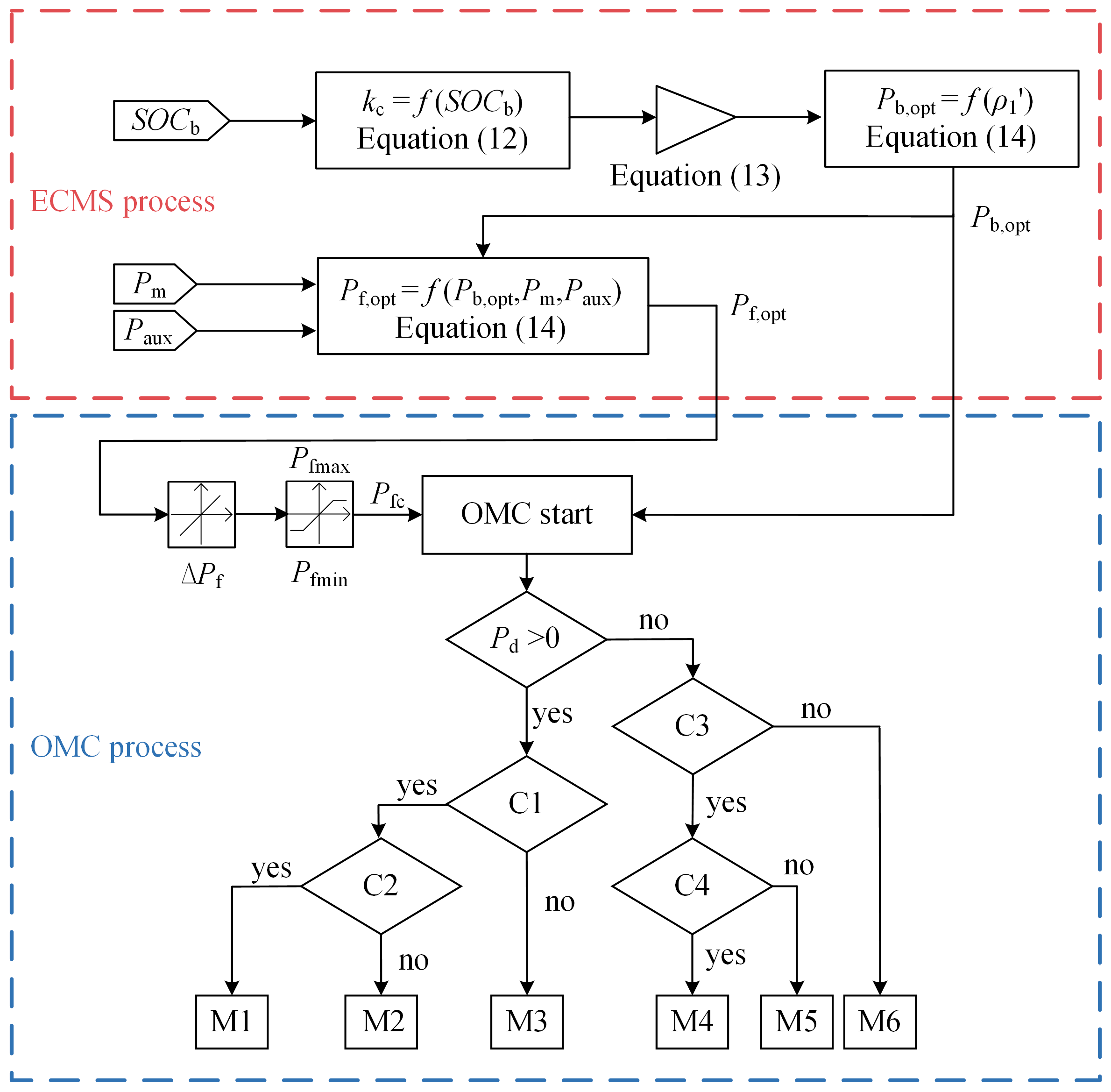
The improved ECMS is based on an assumption: compared to FC and battery, SC aims to generate the peak powers in short periods, and the equivalent consumption of SC can be ignored [21,32]. The strategy contains two processes: the ECMS process and the OMC process. In the ECMS process, P b , o p t and P f , o p t can be calculated according to Section 3.1, and they are used as the input variables of the OMC process.
In the OMC process, the slope limitation and maximum/minimum limitation is considered. FC actual output power P f can be determined at first. Then, six modes are defined. According to correlated variables and conditions, battery actual power output P b and SC actual power output P s can then finally be determined. The structure of the improved ECMS is depicted in Figure 3, where P f m a x and P f m i n are the maximum power and minimum power limitations of the FC, respectively, P d is the power demand of DC bus, C 1 , C 2 , C 3 , and C 4 represent the judgment conditions, M 1 , M 2 , M 3 , M 4 , M 5 , and M 6 represent the operating modes of the vehicle.
Because the energy storage system of the LF-LRV contains two power sources: battery and supercapacitor, the improved ECMS can be divided into two types by the priority of energy supply in ESS: battery-prior ECMS (BP-ECMS) and supercapacitor-prior ECMS (SP-ECMS). Their judgment conditions and operating modes are summarized in Table 1, where P b m a x and P b m i n are the maximum power and minimum power limitations of the battery, respectively, P s m a x and P s m i n are the maximum power and minimum power limitations of SC, respectively, S O C bh and S O C s h are the maximum SOC limitations of battery and SC, respectively, P b r is the output power of braking resistor. The comparison of BP-ECMS with SP-ECMS will be shown in Section 5.
So far, the ECMS has been applied to the PEMFC/battery/SC light rail vehicle. ECMS aims to solve the optimization problem in Equation (7), which is to minimize the instantaneous fuel consumption. However, to evaluate the performance of the vehicle comprehensively, many more factors need to be considered such as the total fuel consumption, replacement and investment costs of power sources. These factors can be considered as global performance. The next section attempts to enhance the global performance of ECMS for the hybrid vehicle.

4. Optimal Control Strategy

Researchers often use the meta-heuristic algorithms to improve the global performance of the control strategy for the hybrid vehicle [24,25,44]. With this in mind, this section attempts to optimize the ECMS by the meta-heuristic algorithm. First, a meta-heuristic algorithm - the firefly algorithm, is detailed. Then, an optimization objective is introduced to evaluate the global performance of the vehicle. Finally, the optimizing ECMS with the firefly algorithm is proposed.

4.1. Firefly Algorithm

Yang [48] developed a meta-heuristic optimizer named the firefly algorithm, which is inspired by the flashing light of fireflies. Compared with other classical meta-heuristic algorithms, such as GA and PSO, the FA showed a better optimization efficiency [48]. Therefore, the algorithm is widely used in many engineering fields [49,50,51] and is adopted in this paper.
In FA, the higher the brightness of the firefly is the more attractive it is, and the attraction of each firefly can be calculated:
β = β 0 e γ r 2
where β 0 is the attraction at r = 0 . The distance between any two fireflies i and j at x i and x j respectively, is r i j = x i x j . For any given two fireflies, x i and x j , the movement of firefly i is attracted to another firefly j , which is more attractive:
x i = x i + β 0 e γ r i j 2 ( x j x i ) + α ε i
where the third term represents random movement, α and ε i are the randomization parameter and a vector of random numbers respectively.
To calculate the attraction of the firefly by Equation (15), an optimization objective will be defined in the next section.

4.2. Optimization Objective

For the PEMFC/battery/SC light rail vehicle, reducing the fuel consumption of the FC system might lead to an increase in the use of the ESS and hence accelerate the degradation of it, and vice versa. This can be regarded as a multi-objective problem.
To solve the multi-objective problem, one needs to define an optimization objective, which determines the optimized direction. Considering the scenario of this paper, the objective is defined as follows:
min X Ω C t r a m ( X ) = [ C f c ( X ) , C s c ( X ) , C b a t ( X ) ]
With
{ C f c = ( F C f u e l + F C c a + F C r e + F C m ) / 365 C s c = ( S C c a + S C r e + S C m + S C chg ) / 365 C b a t = ( B A T c a + B A T r e + B A T m + B A T chg ) / 365
where C t r a m is the total operating cost of the vehicle, C f c , C s c and C b a t are the cost models of the PEMFC system, SC pack, and battery pack, respectively.
F C f u e l is the annualized total fuel cost due to the PEMFC system operation:
F C f u e l = m f u e l C f u e l = C f u e l P f LHV η fc d t
where m f u e l is the fuel consumption of the PEMFC, C f u e l is the cost of the fuel, LHV is the low heat value of hydrogen, and η fc is the PEMFC efficiency.
F C c a is the annualized capital cost related to the initial investment:
F C c a = ( P d c _ f c C d c + C a f c C f c ) C R F
where P d c _ f c is the DC-DC rated power of the PEMFC system, C d c is the cost of the DC-DC, C a f c is the rated power of the PEMFC system, C f c is the cost of the PEMFC, and CRF is the capital recovery factor.
F C r e is the annualized replacement cost:
F C r e = i = 1 N r _ f c ( 1 + I ) i L i f e f c C a f c C f c C R F
With
N r _ f c = ceil ( T L i f e fc 1 )
where ceil(x) is the function that returns the smallest integer that is not less than x, I is the interest rate, T is the lifetime of the system, L i f e fc is the life expectancy of the PEMFC and F C m is the average maintenance cost.
S C c a , S C r e , S C m , and S C chg are the annualized capital cost, the annualized replacement cost, the annualized maintenance cost, and the annualized charged cost of the SC pack, respectively. B A T c a , B A T r e , B A T m , and B A T chg are the annualized capital cost, the annualized replacement cost, the annualized maintenance cost, and the annualized charged cost of the battery pack, respectively. They are defined as follows:
{ E S S c a = ( P d c _ ess C d c + C a e s s C ess ) C R F E S S r e = i = 1 N r _ e s s ( 1 + I ) i L i f e e s s C a e s s C e s s C R F E S S chg = E e s s ( S O C init _ e s s S O C end _ e s s ) C g r i d ξ d c
where the ESS/ess can represent the BAT or SC scenario. E e s s is a function that calculates the energy of the battery or supercapacitor from the termination state S O C init _ e s s to the initial state S O C end _ e s s , C g r i d is the cost of the energy from the grid, and ξ d c is the efficiency of the DC-DC. The definitions of other symbols in Equation (23) are similar to the PEMFC scenario. F C m , S C m , and B A T m are considered the fixed value.
In Equation (18), the F C c a , S C c a , and B A T c a are related to the sizing of the corresponding power sources. Besides, the F C r e , S C r e , and B A T r e are related to the lifecycle of the power sources. Moreover, the S C chg and B A T chg are used to calculate the electricity costs which the power sources recharge to the initial state. The cost models in Equation (18) are expressed in economic terms, and have been detailed by our previous research in [26].
The feasible solution space Ω is subject to the following constraints:
{ 30 % S O C b 90 % 30 % S O C s 100 % 10   kW P f 170   kW 200   kW P b 200   kW 300   kW P s 300   kW 20   kW / s d P f d t 20   kW / s
These constraints aim to ensure that the power sources do not overcharge or over-discharge, while also taking the limit of device operating conditions into account. It is worth to mention that the optimization objective Equation (18) is used to evaluate the global performance of the hybrid vehicle.

4.3. Control Strategy

So far, a new control framework can be proposed, and its aim is to get better global performance than the ECMS. The framework, named the firefly algorithm-based ECMS (F-ECMS), is applied to FA in order to optimize the variables of ECMS proposed in Section 3.2, and the objective is to minimize the total operating cost for PEMFC/battery/SC light rail vehicle.
The choice of optimized variables affects the results of the optimization problem. As shown in Figure 3, the ECMS contains two processes. In the ECMS process, the calculation of P b , opt depends on the balance factor μ b and S O C b , as seen in Equations (12)–(14). The relationships between P b , opt and S O C b , with different balance factor (BF), are illustrated in Figure 4a. It means that the balance factor can affect P b , opt , and so affect P f , opt . For this reason, the balance factor μ b is selected as the optimized variables.
Moreover, in the OMC process, the maximum power and minimum power limitations of power sources (e.g., P fmax , P bmax , P smax etc.) have a large impact on the choice of operating mode, and thus affect the vehicle performance, as seen in Figure 3 and Table 1. So, these power limitations of power sources are considered as the candidates of optimized variables.
After the optimized variables are selected, the process of F-ECMS can be determined:
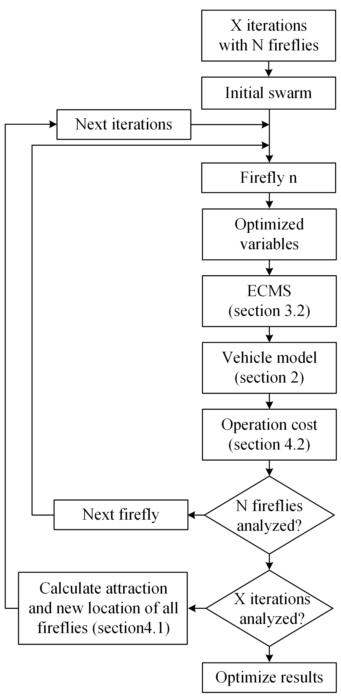
Step 1: Determine the number of iterations X and fireflies N.
Step 2: According to the selected optimal variables, initial the swarm of firefly within the confined region.
Step 3: Take out the nth firefly, it represents a solution. Put it to the ECMS (Section 3.2).
Step 4: Apply the above-mentioned ECMS to the vehicle model (Section 2). Then the model is used for simulation.
Step 5: According to the simulation results, calculate the global performance index C tram (Section 4.2).
Step 6: Repeat steps 3 to 5 until the corresponding performance index of all fireflies are acquired.
Step 7: Calculate the attraction of each firefly with Equation (15) and update the locations of all fireflies with Equation (16).
Step 8: Repeat steps 6 and 7 until X iterations are complete.
Step 9: The location of the most attractive firefly is the best solution for the optimization problem.
The flowchart of the F-ECMS process is summarized in Figure 5.
In order to reveal the impact of the optimized variables selection on optimization effect, a comparison between two different sets of optimized variables is made. The one set is to optimize the signal variable: balance factor μ b . Another set is to optimize multiple variables: balance factor and power limitations. The optimized process and results of two sets are shown in Figure 4b, where ‘S-OV’ means the situation of signal optimized variable, ‘M-OV’ means the situation of multiple optimized variables, and ‘B-data’ means the situation of the benchmark data produced by ECMS. The higher attraction means a better effect. It can be seen that:
  • Only optimizing the balance factor of F-ECMS can obtain a better result (2.875) than ECMS (2.826).
  • Optimizing the balance factor and power limitations can obtain the best result (3.279).
So, both balance factor and power limitations are selected to the optimized variables for F-ECMS in this paper.

5. Results and Analysis

This section reports the validation of the proposed strategy in the LF-LRV scenario. In order to verify the control strategy, the model of the vehicle is constructed using MATLAB/Simulink, as shown in Figure 6. The model according to the target speed profile, calculates the speed demand, torque demand, or power demand of each part for the hybrid vehicle. The comparison between actual data and model simulation of the vehicle has been proposed in our previous research [52], and the error is less than 1%.
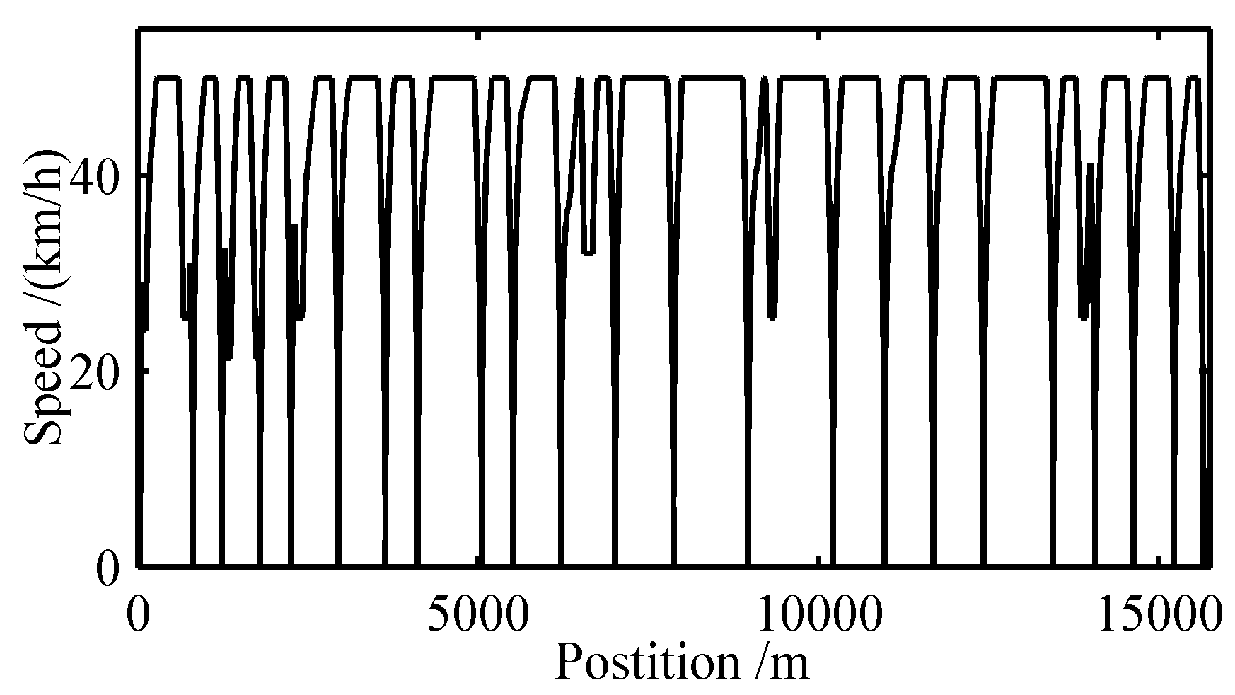
The driving cycle is based on the Guanggu T1 line in Wuhan, China, which is 15 km in length and has 23 stations. The corresponding target speed profile of the vehicle as shown in Figure 7.
To accomplish the driving cycle, the PEMFC system’s power of the vehicle should be above the cycle’s average power, which is 200.8 kW. So, two PEMFC systems are selected, and its rated power is 150 kW. The peak traction power and braking power of the driving cycle are 696.7 kW and 636.7 kW. So, the hybrid system, in a motor unit, consists of an FC system (150 kW), two battery packs (40 Ah) and three SC packs (45 F). The basic parameters of the power sources are summarised in Table 2, and the parameters of the objective function can be found in [26].
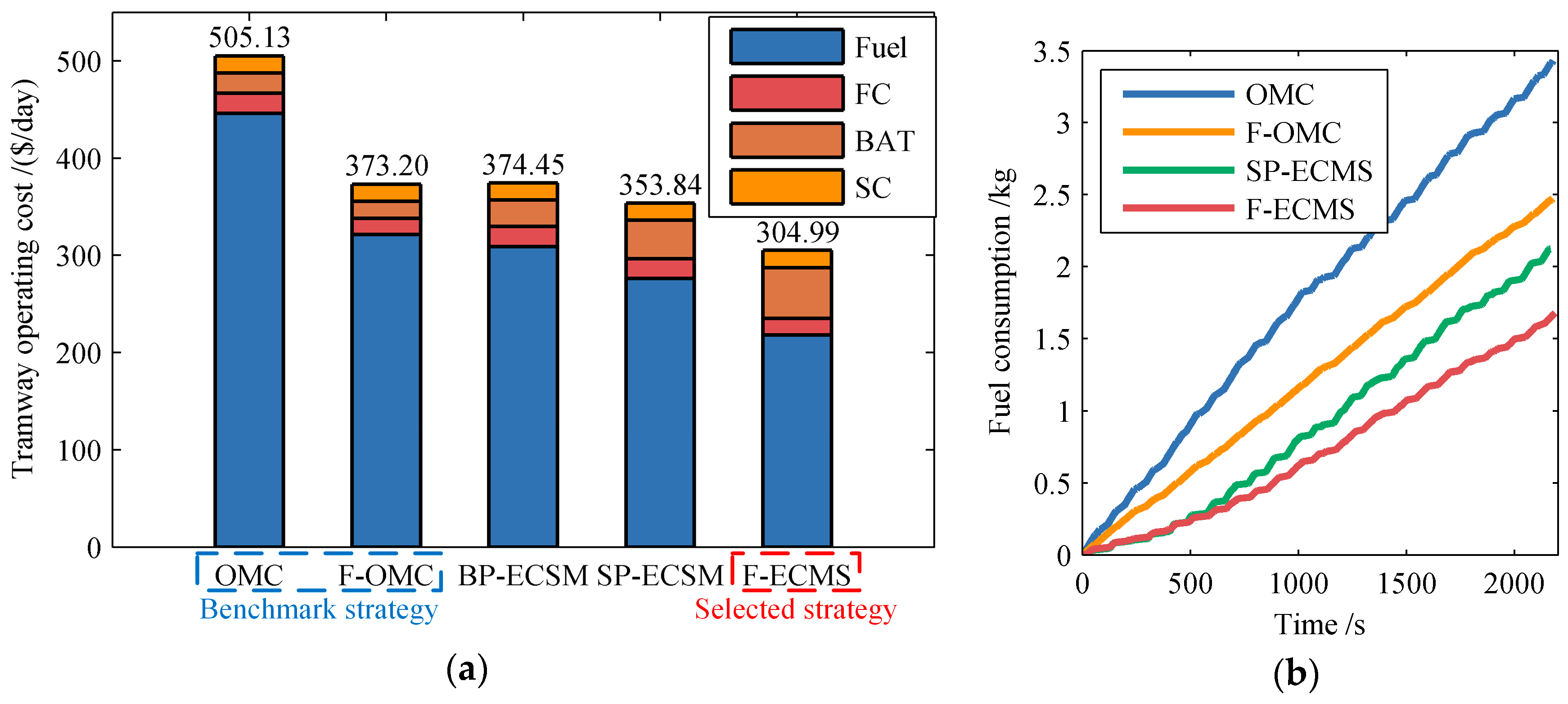
To show the performance of the strategy mentioned in this paper clearly, two strategies are chosen as benchmarks: one is the OMC strategy [26], and another is FA-based OMC (F-OMC), which uses the FA to optimize the power limitations of OMC. Their corresponding operation cost of the vehicle is as shown in Figure 8a. Because of the FA optimizing, the F-OMC ($373.20/day) can get lower costs than OMC ($505.13/day). It is worth to mention that in Figure 8a, the ‘Fuel’ cost represents the fuel cost consumed by the FC system, and the ‘FC’ cost includes the cost of initial investment, replacement, and maintenance for the FC system.
First, two types of ECMS: BP-ECMS and SP-ECMS, have been evaluated. The corresponding operating costs are shown in Figure 8a. Compared with the OMC ($505.13/day), the costs based on the BP-ECMS ($374.45/day) and SP-ECMS ($353.84/day) can be decreased to varying degrees. It is because the ECMS can optimize fuel consumption, which is the major part of the operating cost. Besides, the cost of SP-ECMS is lower than BP-ECMS. The reason is as follows; when compared with BP-ECMS, the usage of battery in SP-ECMS is higher, which results in a reduction of fuel cost. It can also be seen that the result of SP-ECMS is better than F-OMC ($373.20/day), due to the good instantaneous performance of the ECMS. As the operating costs of SP-ECMS precede BP-ECMS as mentioned above, the SP-ECMS is used to represent the ECMS in a followed comparison. Moreover, in this paper, the F-ECMS combines the FA and SP-ECMS.
Then, the F-ECMS has been evaluated. The result is shown in Figure 8a. Compared with SP-ECMS ($353.84/day), the operating costs of F-ECMS ($304.99/day) could be further reduced, due to the introduction of FA. It also proves that F-ECMS has the best global performance in this paper.
To observe the fuel economy of the strategies, the total fuel consumption resulting for the driving cycle are shown in Figure 8b. The fuel consumption of the F-ECMS is 1.68 kg, the OMC is 3.43 kg, the F-OMC is 2.47 kg, and the SP-ECMS is 2.12 kg. It means that, compared with OMC, the introduction of the ECMS (i.e. SP-ECMS) or FA (i.e. F-OMC) can improve the fuel economy for the hybrid vehicle, and combine both of them (i.e. F-ECMS) to achieve the best results.
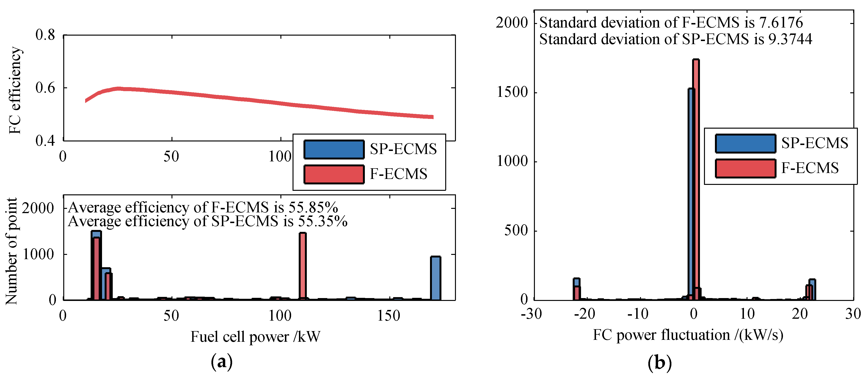
In order to demonstrate the performance advantage of the F-ECMS compared with SP-ECMS more clearly, the operating point distributions of the FC system are shown in Figure 9a. The FC system output power is mainly distributed in two regions: low-power region and high-power region. The low-power region of SP-ECMS and F-ECMS is around 18 kW, which means that the vehicle operates in the regenerative braking phase. Because of the optimization of FC power limitations, the high-power region of F-ECMS around 115 kW. In contrast, the high-power region of SP-ECMS around 170 kW. This should result in the average efficiency of F-ECMS (55.85%) is high than SP-ECMS (55.35%).
The fluctuation distribution comparison of FC power between F-ECMS and SP-ECMS is shown in Figure 9b, and the lower standard deviation means the better life expectancy of the FC system. By using FA to optimize the SP-ECMS, the limiting effect of F-ECMS (7.6176) is better than SP-ECMS (9.3744).
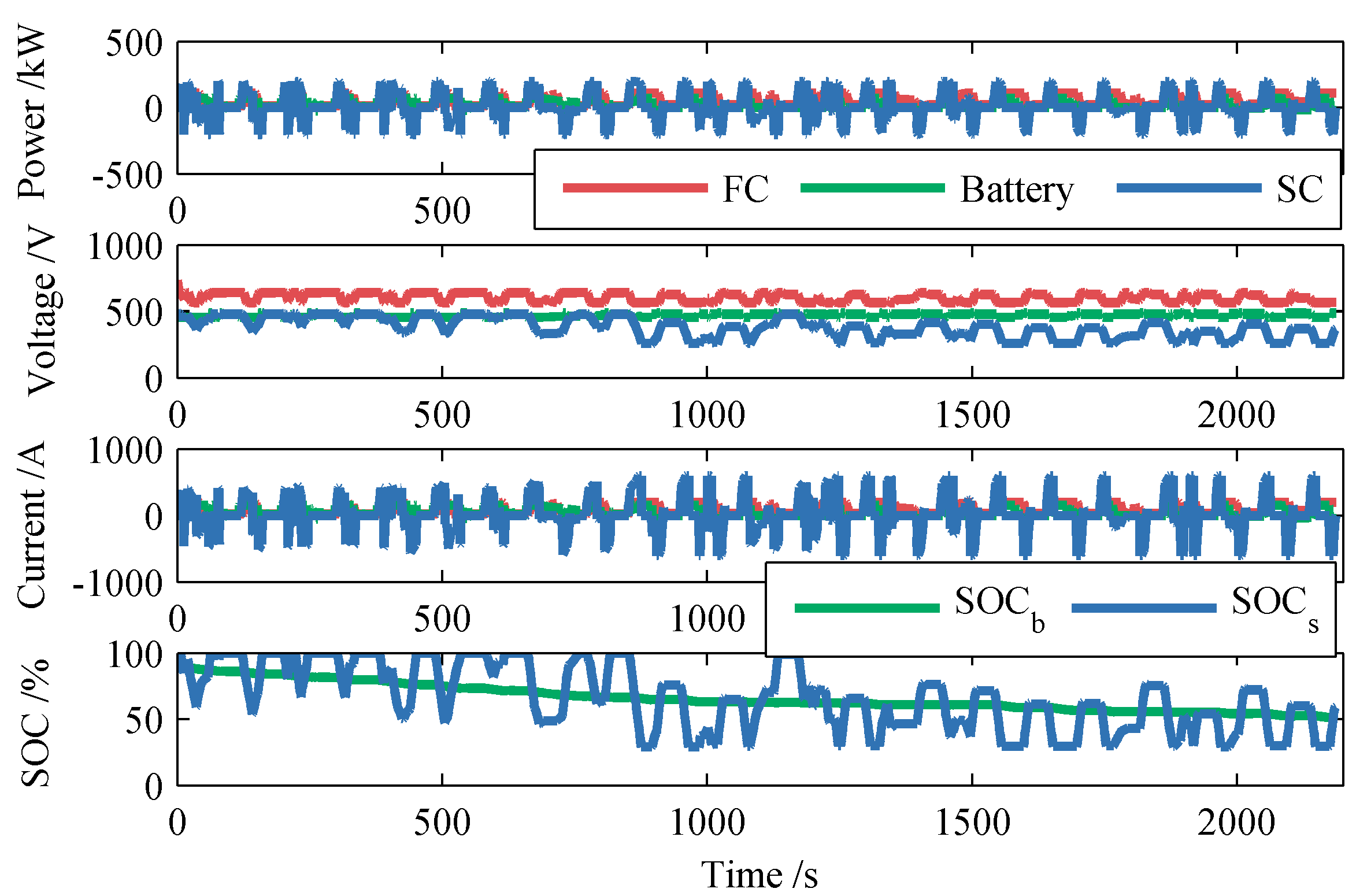
As the main objective of this paper is to minimize the operation cost, the F-ECMS is finally selected as the control strategy for the LF-LRV. The power curves of the power sources for F-ECMS are illustrated in Figure 10. It can be seen that the F-ECMS can ensure that the hybrid system works steadily, and that the output power among the power sources rational distribution. Table 3 summarizes the improvement of F-ECMS compared with the OMC, F-OMC, and SP-ECMS.

6. Conclusions

This paper presents the optimal control strategy for a light rail vehicle, which is powered by the fuel cell, battery, and supercapacitor. The aim is to improve the global performance of the equivalent consumption minimization strategy (ECMS).
As the conventional ECMS cannot be directly applied to the fuel cell/battery/supercapacitor hybrid system, a strategy combined ECMS and operating mode control is presented. Then, the firefly algorithm is introduced to optimize the strategy, in order to enhance the global performance. The optimization objective is to minimize the operating costs of the vehicle, which contains the total fuel consumption, initial investment, and replacement costs of power sources. The balance factor and power limitations are considered as the candidate of the optimized variables.
A 100% low-floor light rail vehicle is selected as the case study. The operation costs of the vehicle based on battery-prior ECMS, supercapacitor-prior ECMS, and the proposed strategy are obtained. The operating mode control and firefly algorithm-based operating mode control are used as benchmarks. The simulation results indicate that the proposed strategy offers the lowest operating cost. Compared with operating mode control, firefly algorithm-based operating mode control, and supercapacitor-prior ECMS, the proposed strategy can save 39.62%, 18.28%, and 13.81% cost, respectively. Moreover, the strategy can reduce fuel consumption and increase the efficiency of the fuel cell system. It can be concluded that among all of the strategies mentioned above, the proposed strategy not only satisfies the power/energy demand, but also offers the best global performance for the hybrid vehicle.

Author Contributions

Conceptualization, H.Z.; methodology, H.Z.; software, H.Z. and J.Y.; validation, J.Y. and P.S.; formal analysis, H.Z.; investigation, H.Z. and J.Y.; resources, J.Z. and P.S.; data curation, H.Z.; writing—original draft preparation, H.Z.; writing—review and editing, H.Z., J.Y. and J.Z.; visualization, H.Z. and J.Y.; supervision, J.Z., P.S. and X.X.; project administration, J.Z., P.S. and X.X.; funding acquisition, J.Z. and J.Y.

Funding

This research was funded by the National Natural Science Foundation of the People’s Republic of China, grant number 11572264; the Science and Technology Major Project of Sichuan Province, grant number 2019ZDZX0002; the Open Research Subject of Key Laboratory of Fluid and Power Machinery (Xihua University), Ministry of Education, grant number szjj2019-015.

Conflicts of Interest

The author declares no conflict of interest.

References

  1. Yue, M.; Jemei, S.; Gouriveau, R.; Zerhouni, N. Review on Health-Conscious Energy Management Strategies for Fuel Cell Hybrid Electric Vehicles: Degradation Models and Strategies. Int. J. Hydrogen Energy 2019, 44, 6844–6861. [Google Scholar] [CrossRef]
  2. Hidalgo-Reyes, J.I.; Gomez-Aguilar, J.F.; Escobar-Jimenez, R.F.; Alvarado-Martinez, V.M.; Lopez-Lopez, M.G. Classical and Fractional-order Modeling of Equivalent Electrical Circuits for Supercapacitors and Batteries, Energy Management Strategies for Hybrid Systems and Methods for the State of Charge Estimation: A State of the Art Review. Microelectron. J. 2019, 85, 109–128. [Google Scholar] [CrossRef]
  3. Hong, Z.; Li, Q.; Han, Y.; Shang, W.; Zhu, Y.; Chen, W. An Energy Management Strategy based on Dynamic Power Factor for Fuel Cell/battery Hybrid Locomotive. Int. J. Hydrogen Energy 2018, 43, 3261–3272. [Google Scholar] [CrossRef]
  4. Cheng, J.; Yang, G.; Zhang, K.; He, G.; Jia, J.; Yu, H.; Gai, F.; Li, L.; Hao, C.; Zhang, F. Guanidimidazole-quanternized and Cross-linked Alkaline Polymer Electrolyte Membrane for Fuel Cell Application. J. Membr. Sci. 2016, 501, 100–108. [Google Scholar] [CrossRef]
  5. Kamal, T.; Hassan, S.Z.; Espinosa-Trujillo, M.J.; Li, H.; Flota, M. An Optimal Power Sharing and Power Control Strategy of Photovoltaic/Fuel Cell/Ultra-capacitor Hybrid Power System. J. Renew. Sustain. Energy 2016, 8, 035301. [Google Scholar] [CrossRef]
  6. Marzougui, H.; Amari, M.; Kadri, A.; Bacha, F.; Ghouili, J. Energy Management of Fuel Cell/Battery/Ultracapacitor in Electrical Hybrid Vehicle. Int. J. Hydrogen Energy 2017, 42, 8857–8869. [Google Scholar] [CrossRef]
  7. Fathabadi, H. Fuel Cell Hybrid Electric Vehicle (FCHEV): Novel Fuel Cell/SC Hybrid Power Generation System. Energy Convers. Manag. 2018, 156, 192–201. [Google Scholar] [CrossRef]
  8. Das, H.; Tan, C.; Yatim, A. Fuel Cell Hybrid Electric Vehicles: A Review on Power Conditioning Units and Topologies. Renew. Sustain. Energy Rev. 2017, 76, 268–291. [Google Scholar] [CrossRef]
  9. Garcia, P.; Fernandez, L.; Torreglosa, J.; Jurado, F. Comparative Study of Four Control Systems for a 400-kW Fuel Cell Battery-Powered Tramway with Two DC/DC Converters. Int. Trans. Electr. Energy Syst. 2013, 23, 1028–1048. [Google Scholar] [CrossRef]
  10. Behdani, A.; Naseh, M. Power Management and Nonlinear Control of a Fuel Cell-Supercapacitor Hybrid Automotive Vehicle with Working Condition Algorithm. Int. J. Hydrogen Energy 2017, 42, 24347–24357. [Google Scholar] [CrossRef]
  11. Zhou, D.; Al-Durra, A.; Gao, F.; Ravey, A.; Matraji, I.; Simoes, M. Online Energy Management Strategy of Fuel Cell Hybrid Electric Vehicles Based on Data Fusion Approach. J. Power Sources 2017, 366, 278–291. [Google Scholar] [CrossRef]
  12. Bauman, J.; Kazerani, M. A Comparative Study of Fuel-Cell-Battery, Fuel-Cell-Ultracapacitor, and Fuel-Cell-Battery-Ultracapacitor Vehicles. IEEE Trans. Veh. Technol. 2008, 57, 760–769. [Google Scholar] [CrossRef]
  13. Li, Q.; Yang, H.; Han, Y.; Li, M.; Chen, W. A State Machine Strategy Based on Droop Control for an Energy Management System of PEMFC-Battery-Supercapacitor Hybrid Tramway. Int. J. Hydrogen Energy 2016, 41, 16148–16159. [Google Scholar] [CrossRef]
  14. Peng, F.; Zhao, Y.; Li, X.; Liu, Z.; Chen, W.; Liu, Y.; Zhou, D. Development of Master-Slave Energy Management Strategy Based on Fuzzy Logic Hysteresis State Machine and Differential Power Processing Compensation for a PEMFC-LIB-SC Hybrid Tramway. Appl. Energy 2017, 206, 346–363. [Google Scholar] [CrossRef]
  15. Ali, A.M.; Soffker, D. Towards Optimal Power Management of Hybrid Electric Vehicles in Real-Time: A Review on Methods, Challenges, and State-of-the-Art Solutions. Energies 2018, 11, 476. [Google Scholar]
  16. Ahmadi, S.; Bathaee, S.M.T. Multi-Objective Genetic Optimization of the Fuel Cell Hybrid Vehicle Supervisory System: Fuzzy Logic and Operating Mode Control Strategies. Int. J. Hydrogen Energy 2015, 40, 12512–12521. [Google Scholar] [CrossRef]
  17. Caux, S.; Hankache, W.; Fadel, M.; Hissel, D. On-Line Fuzzy Energy Management for Hybrid Fuel Cell Systems. Int. J. Hydrogen Energy 2010, 35, 2134–2143. [Google Scholar] [CrossRef]
  18. Bizon, N. Load-Following Mode Control of a Standalone Renewable/Fuel Cell Hybrid Power Source. Energy Convers. Manag. 2014, 77, 763–772. [Google Scholar] [CrossRef]
  19. Yu, K.; Tan, X.; Yang, H.; Liu, W.; Cui, L.; Liang, Q. Model Predictive Control of Hybrid Electric Vehicles for Improved Fuel Economy. Asian J. Control 2016, 18, 1–14. [Google Scholar] [CrossRef]
  20. Ayad, M.Y.; Becherif, M.; Henni, A. Vehicle Hybridization with Fuel Cell, Supercapacitors and Batteries by Sliding Mode Control. Renew. Energy 2011, 36, 2627–2634. [Google Scholar] [CrossRef]
  21. Zhang, W.; Li, J.; Xu, L.; Ouyang, M. Optimization for a Fuel Cell/Battery/Capacity Tram with Equivalent Consumption Minimization Strategy. Energy Convers. Manag. 2017, 134, 59–69. [Google Scholar] [CrossRef]
  22. Hu, Z.; Li, J.; Xu, L.; Song, Z.; Fang, C.; Ouyang, M.; Dou, G.; Kou, G. Multi-Objective Energy Management Optimization and Parameter Sizing for Proton Exchange Membrane Hybrid Fuel Cell Vehicles. Energy Convers. Manag. 2016, 129, 108–121. [Google Scholar] [CrossRef]
  23. Xu, L.; Yang, F.; Li, J.; Ouyang, M.; Hua, J. Real Time Optimal Energy Management Strategy Targeting at Minimizing Daily Operation Cost for a Plug-in Fuel Cell City Bus. Int. J. Hydrogen Energy 2012, 37, 15380–15392. [Google Scholar] [CrossRef]
  24. Li, M.; Li, M.; Han, G.; Liu, N.; Zhang, Q.; Wang, Y. Optimization Analysis of the Energy Management Strategy of the New Energy Hybrid 100% Low-Floor Tramcar Using a Genetic Algorithm. Appl. Sci. 2018, 8, 1144. [Google Scholar] [CrossRef]
  25. Olivier, J.C.; Wasselynck, G.; Chevalier, S.; Auvity, B.; Josset, C.; Trichet, D.; Squadrito, G.; Bernard, N. Multiphysics Modeling and Optimization of the Driving Strategy of a Light Duty Fuel Cell Vehicle. Int. J. Hydrogen Energy 2017, 42, 26943–26955. [Google Scholar] [CrossRef]
  26. Zhang, H.; Yang, J.; Zhang, J.; Song, P.; Li, M. Optimal Energy Management of a Fuel Cell-Battery-Supercapacitor-Powered Hybrid Tramway Using a Multi-Objective Approach. Proc. Inst. Mech. Eng. Part F J. Rail Rapid Transit 2019. [Google Scholar] [CrossRef]
  27. Zhang, F.; Xu, K.; Li, L.; Langari, R. Comparative Study of Equivalent Factor Adjustment Algorithm for Equivalent Consumption Minimization Strategy for HEVs. In Proceedings of the IEEE Vehicle Power and Propulsion Conference, Chicago, IL, USA, 27–30 August 2018. [Google Scholar]
  28. Li, H.; Ravey, A.; N’Diaye, A.; Djerdir, A. A Novel Equivalent Consumption Minimization Strategy for Hybrid Electric Vehicle Powered by Fuel Cell, Battery and Supercapacitor. J. Power Sources 2018, 395, 262–270. [Google Scholar] [CrossRef]
  29. Lin, X.; Feng, Q.; Mo, L.; Li, H. Optimal Adaptation Equivalent Factor of Energy Management Strategy for Plug-in CVT HEV. Proc. Inst. Mech. Eng. Part D J. Automob. Eng. 2019, 233, 877–889. [Google Scholar] [CrossRef]
  30. Torreglosa, J.P.; Jurado, F.; Garcia, P.; Fernandez, L.M. Hybrid Fuel Cell and Battery Tramway Control Based on an Equivalent Consumption Minimization Strategy. Control Eng. Pract. 2011, 19, 1182–1194. [Google Scholar] [CrossRef]
  31. Zhang, G.; Li, Q.; Han, Y.; Meng, X.; Chen, W. Study on Equivalent Consumption Minimization Strategy Based on Operation Mode and DDOH for Fuel Cell Hybrid Tramway. Proc. CSEE 2018, 23, 6905–6914. [Google Scholar]
  32. Garcia, P.; Torreglosa, J.P.; Fernandez, L.M.; Jurado, F. Viability Study of a FC-Battery-SC Tramway Controlled by Equivalent Consumption Minimization Strategy. Int. J. Hydrogen Energy 2012, 37, 9368–9382. [Google Scholar] [CrossRef]
  33. Yan, Y.; Li, Q.; Chen, W.; Su, B.; Liu, J.; Ma, L. Optimal Energy Management and Control in Multimode Equivalent Energy Consumption of Fuel Cell/Supercapacitor of Hybrid Electric Tram. IEEE Trans. Ind. Electron. 2019, 66, 6065–6076. [Google Scholar] [CrossRef]
  34. Han, Y.; Li, Q.; Wang, T.; Chen, W.; Ma, L. Multisource Coordination Energy Management Strategy Based on SOC Consensus for a PEMFC–Battery–Supercapacitor Hybrid Tramway. IEEE Trans. Veh. Technol. 2018, 67, 296–305. [Google Scholar] [CrossRef]
  35. Yang, J.; Xu, X.; Peng, Y.; Zhang, J.; Song, P. Modeling and Optimal Energy Management Strategy for a Catenary-Battery-Ultracapacitor Based Hybrid Tramway. Energy 2019, 183, 1123–1135. [Google Scholar] [CrossRef]
  36. Yang, J.; Song, P.; Zhang, J.; Wang, G.; Zhang, H. Research on Simulation System of Hybrid Modern Tramway. J. Mech. Eng. 2017, 53, 161–168. [Google Scholar] [CrossRef]
  37. Niu, Q.; Zhang, H.; Li, K. An Improved TLBO with Elite Strategy for Parameters Identification of PEM Fuel Cell and Solar Cell Models. Int. J. Hydrogen Energy 2014, 39, 3837–3854. [Google Scholar] [CrossRef]
  38. Li, Q.; Wang, T.; Dai, C.; Chen, W.; Ma, L. Power Management Strategy Based on Adaptive Droop Control for a Fuel Cell-Battery-Supercapacitor Hybrid Tramway. IEEE Trans. Veh. Technol. 2018, 67, 5658–5670. [Google Scholar] [CrossRef]
  39. Yang, J.; Zhang, J.; Song, P.; Chen, Y.; Wang, G. Research on Modeling and Operation Control of Fuel Cell Hybrid Train. J. China Railw. Soc. 2017, 39, 40–47. [Google Scholar]
  40. Tremblay, O.; Dessaint, L. Experimental Validation of a Battery Dynamic Model for EV Applications. World Electr. Veh. J. 2009, 3, 1–10. [Google Scholar] [CrossRef]
  41. Zhu, Y.; Murali, S.; Stoller, M.; Ganesh, K.; Cai, W.; Ferreira, P.; Pirkle, A.; Wallace, R.; Cychosz, k.; Thommes, M.; et al. Carbon-Based Supercapacitors Produced by Activation of Graphene. Science 2011, 332, 1537–1541. [Google Scholar] [CrossRef] [Green Version]
  42. Ehsani, M.; Gao, Y.; Emadi, A. Modern Electric, Hybrid Electric, and Fuel Cell Vehicles: Fundamentals, Theory, and Design, 2nd ed.; CRC Press: Boca Raton, FL, USA, 2010; pp. 331–333. [Google Scholar]
  43. Herrera, V.; Milo, A.; Gaztanaga, H.; Etxeberria-Otadui, I.; Villarreal, I.; Camblong, H. Adaptive Energy Management Strategy and Optimal Sizing Applied on a Battery-Supercapacitor Based Tramway. Appl. Energy 2016, 169, 831–845. [Google Scholar] [CrossRef]
  44. Herrera, V.; Gaztanaga, H.; Milo, A.; Saez-de-Ibarra, A.; Etxeberria-Otadui, I.; Nieva, T. Optimal Energy Management and Sizing of a Battery-Supercapacitor-Based Light Rail Vehicle with a Multiobjective Approach. IEEE. Trans. Ind. Appl. 2016, 52, 3367–3377. [Google Scholar] [CrossRef]
  45. Paganelli, G.; Delprat, S.; Guerra, T.M.; Rimaux, J.; Santin, J.J. Equivalent Consumption Minimization Strategy for Parallel Hybrid Powertrains. In Proceedings of the IEEE 55th Vehicular Technology Conference, Birmingham, AL, USA, 6–9 May 2002. [Google Scholar]
  46. Xu, L.; Li, J.; Hua, J.; Li, X.; Ouyang, M. Adaptive Supervisory Control Strategy of a Fuel Cell/Battery-Powered City Bus. J. Power Sources 2009, 194, 360–368. [Google Scholar] [CrossRef]
  47. Garcia, P.; Fernandez, L.M.; Torreglosa, J.P.; Jurado, F. Operation Mode Control of a Hybrid Power System Based on Fuel Cell/Battery/Ultracapacitor for an Electric Tramway. Comput. Electr. Eng. 2013, 39, 1993–2004. [Google Scholar] [CrossRef]
  48. Yang, X. Firefly algorithms for multimodal optimization. In Proceedings of the International Symposium on Stochastic Algorithms, Sapporo, Japan, 26–28 October 2009. [Google Scholar]
  49. Chaurasia, G.S.; Singh, A.K.; Agrawal, S.; Sharma, N.K. A Meta-Heuristic Firefly Algorithm Based Smart Control Strategy and Analysis of a Grid Connected Hybrid Photovoltaic/Wind Distributed Generation System. Sol. Energy 2017, 150, 265–274. [Google Scholar] [CrossRef]
  50. Wang, D.; Luo, H.; Grunder, O.; Lin, Y.; Guo, H. Multi-Step Ahead Electricity Price Forecasting Using a Hybrid Model Based on Two-Layer Decomposition Technique and BP Neural Network Optimized by Firefly Algorithm. Appl. Energy 2017, 190, 390–407. [Google Scholar] [CrossRef]
  51. Bahadormanesh, N.; Rahat, S.; Yarali, M. Constrained Multi-Objective Optimization of Radial Expanders in Organic Rankine Cycles by Firefly Algorithm. Energy Convers. Manag. 2017, 148, 1179–1193. [Google Scholar] [CrossRef]
  52. Yang, J.; Xu, X.; Zhang, J.; Song, P. Multi-objective Optimization of Energy Management Strategy for Fuel Cell Tram. J. Mech. Eng. 2018, 22, 153–159. [Google Scholar] [CrossRef]
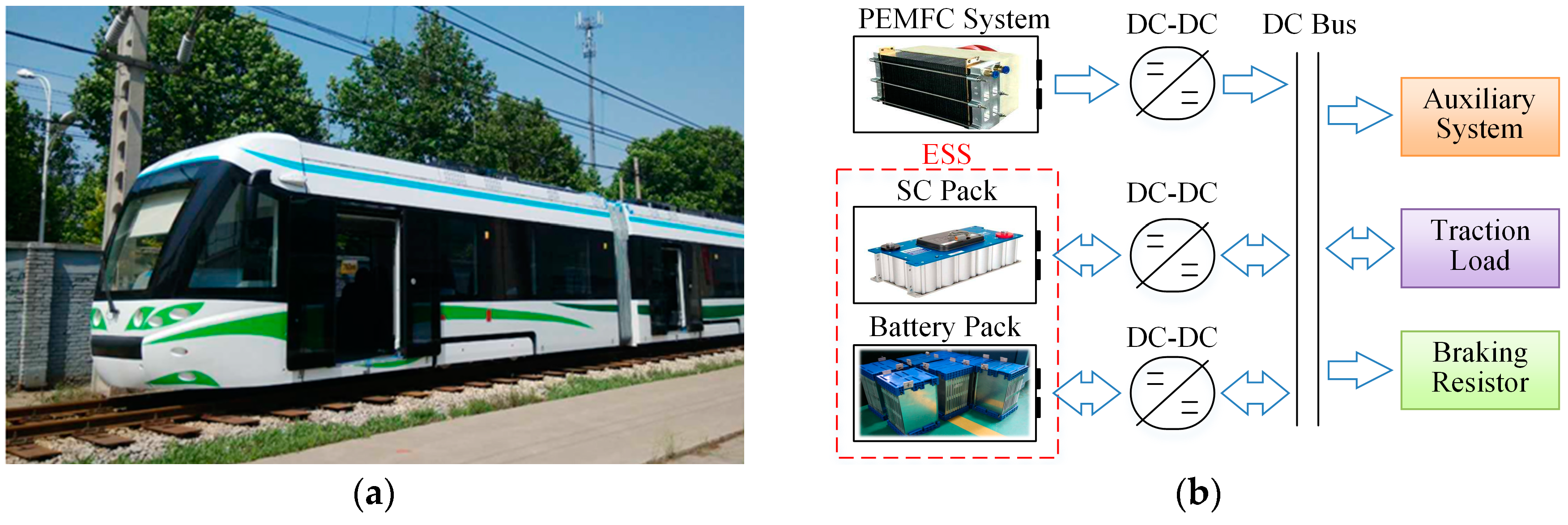
Figure 1. The low-floor light rail vehicle: (a) realistic images; (b) structure of the hybrid system.
Energies 12 02665 g001
Figure 2. The data of power sources: (a) efficiency of proton exchange membrane fuel cell system; (b) open circuit voltage-state of charge curve of battery.
Energies 12 02665 g002
Figure 3. The structure of improved equivalent consumption minimization strategy (ECMS).
Energies 12 02665 g003
Figure 4. The choice of the optimized variables: (a) the relationship between Pb,opt and SOCb; (b) optimized process of the firefly algorithm-based equivalent consumption minimization strategy (F-ECMS).
Energies 12 02665 g004
Figure 5. The process of F-ECMS.
Energies 12 02665 g005
Figure 6. Vehicle simulation model.
Energies 12 02665 g006
Figure 7. Target speed profile.
Energies 12 02665 g007
Figure 8. The results of different strategies: (a) optimal solutions and operating cost; (b) fuel consumption.
Energies 12 02665 g008
Figure 9. The results of fuel cell (FC) System: (a) distribution comparison; (b) power fluctuations.
Energies 12 02665 g009
Figure 10. Performance of power sources for F-ECMS.
Energies 12 02665 g010
Table 1. The conditions and modes of operating mode control (OMC) process for ECMS.
Condition/ModeBP-ECMSSP-ECMS
C1 P b , o p t < P b m a x P d P f P b , o p t < P s m a x
C2 P b , o p t > P b m i n P d P f P b , o p t > P s m i n
C3 ( P b , o p t > 0 ) & ( S O C s > S O C s h ) ( P b , o p t > 0 ) & ( S O C s > S O C s h )
C4 S O C b < S O C b h S O C b < S O C b h
M1 P b = P b , o p t , P s = P d P f P b P s = P d P f P b , o p t , P b = P d P f P s
M2 P b = P b m i n , P s = P d P f P b P s = P s m i n , P b = P d P f P s
M3 P b = P b m a x , P s = P d P f P b P s = P s m a x , P b = P d P f P s
M4 P s = P s m a x , P b = P d P f P s P s = P s m a x , P b = P d P f P s
M5 P b = P b , o p t , P s = P s m a x , P b r = P d P f P b P s P b = P b , o p t , P s = P s m a x , P b r = P d P f P b P s
M6 P b = P b , o p t , P s = P d P f P b P s = P d P f P b , o p t , P b = P d P f P s
Table 2. Basic parameters of power sources.
Power sourceParameterValue
PEMFCMaximum power (kW)170
Rated voltage (V)540
Maximum current (A)320
Cell number735
Battery cellRated voltage (V)3.2
Rated capacity (Ah)40
Operating voltage (V)2.5–3.8
Operating temperature (K)253–318
SC cellRated voltage (V)2.7
Rated capacity (F)3000
Maximum current (A)210
Operating temperature (K)233–335
Table 3. The improvement of F-ECMS.
IndicatorsOMCF-OMCSP-ECMS
MethodsIntroduces ECMS and FAIntroduces ECMSOptimized by FA
Operating costSave 39.62%Save 18.28%Save 13.81%
Fuel consumptionSave 51.02%Save 31.98%Save 20.75%
FC system efficiencyImprove 3.34%Improve 0.88%Improve 0.5%