Abstract
The thermodynamic cycle, as a significant tool derived from equilibrium, could provide a reasonable and rapid energy profile of complicated energy systems. Such a function could strongly promote an in-depth and direct understanding of the energy conversion mechanism of cutting-edge industrial systems, e.g., carbon capture system (CCS) However, such applications of thermodynamics theory have not been widely accepted in the carbon capture sector, which may be one of the reasons why intensive energy consumption still obstructs large-scale commercialization of CCS. In this paper, a kind of thermodynamic cycle was developed as a tool to estimate the lowest regeneration heat (Qre) of a benchmark solvent (MEA) under typical conditions. Moreover, COPCO2, a new assessment indicator, was proposed firstly for energy-efficiency performance analysis of such a kind of CCS system. In addition to regeneration heat and second-law efficiency (η2nd), the developed COPCO2 was also integrated into the existing performance analysis framework, to assess the energy efficiency of an amine-based absorption system. Through variable parameter analysis, the higher CO2 concentration of the flue gas, the higher COPCO2, up to 2.80 in 16 vt% and the Qre was 2.82 GJ/t, when Rdes = 1 and ΔTheat-ex = 10 K. The η2nd was no more than 30% and decreased with the rise of the desorption temperature, which indicates the great potential of improvements of the energy efficiency.
1. Introduction
Due to the activities of human beings, the concentration of CO2—the main greenhouse gases, which accounts for 76%—has passed 400 ppm and now reached a new high level of 415 ppm, on 13
May 2019 [1,2]. The Intergovernmental Panel on Climate Change (IPCC) indicated the rise of global mean temperature is limited to 1.5 °C rather than 2.0 °C, and it will definitely bring more benefits to humans and natural ecosystems. At the same time, by 2030, global CO2 emissions need to fall by 45% compared to 2010 [3,4]. In order to achieve this goal, efforts of all components of our society are required. CCS plays a vital role in the mitigation of climate change, which could contribute 14% to the reduction of CO2 emission according to the International Energy Agency (IEA) [5]. With the development of CCS technologies, amine-based post-combustion technologies could approach a commercial-scale project first, which remains the preferred CO2 capture technology for the short and medium term [6,7]. However, high energy consumption obstructs the popularization and application of CCS [8]. In recent years, many researchers have given much attention to the development of new amine-based solvents. Table 1 summarizes the energy performance of three kinds of new amine-based solvents.

Table 1.
Energy consumption performance of different chemical absorbents.
A blend of amines solvents integrates the properties and advantages of various amines, such as a classic combination of primary amines (e.g., MEA) or secondary amines (e.g., DEA) mixed with tertiary amines (e.g., MDEA) [32,33]. The performance of this kind of solvent, which combines the high reaction rate of primary or secondary amines with the high absorption capacity and lower absorption heat of tertiary amines, has been tested at the pilot scale or even higher scales for many years [34,35]. Additionally, ionic liquids (ILs) are also a kind of modifier, which possess suitable characteristics, such as high thermal stability, nonflammability, and high CO2 solubility [36]. Researchers added ILs into amines in an attempt to improve the absorption ability of solvents and reduce the energy consumption of regeneration [37,38]. Gao et al. [39] added [Bmim][BF4] into MDEA/PZ, with the result showing larger CO2 cyclic capacities, which indicated that the anion species of ILs could lower the sensible heat. However, one of the inevitable problems with IL solvents is that the viscosity of the solution will increase. Then, as a result, it brings a decrease of the mass transfer rate and reaction rate along with the absorption process [40,41]. Despite these good advantages, including being environmentally-friendly, the expensive cost of ILs is an obstruction, whose price are up to 1000 $/kg, limiting its application at large scales [42].
In the regeneration process, due to the high specific heat of water, plenty of heat is used to the sensible heat and the latent heat of steam [43]. Then, a kind of amine-based solvent, water-lean/nonaqueous absorbents, has gain the attention of researchers. The most common method is to reduce the proportion of water in solution, even to water-free. Water-lean or nonaqueous absorbents replace the water by organics, such as alcohols and glycols, to maintain the advanced capability of the absorption of CO2, like aqueous amines [44]. However, the changes are not always beneficial to all processes. The high viscosity of the solutions/absorbents leads to poor mass transfer, which strongly affects the absorption capacity [45,46]. Furthermore, nonaqueous solvent components with lower molecular weights may pollute the air because of the presence of volatile organic emissions in the exhaust [22]. The feasibility of water-lean/nonaqueous absorbents entails a deeper exploration and higher scale demonstration.
In recent years, phase change solvents have caught the attention of researchers. Phase change solvents are single-phase solvents before absorbing CO2 or being heated, and if the CO2 loading or temperature is changed, they will transform into a two-phase (liquid–liquid or liquid–solid). Then, only the CO2-enriched phase is sent to the regeneration process. There will be a heat decrease due to the mass of the solvents reducing. Liu et al. [30] developed a novel phase change solvent, DEEA (50 wt%)-AEEA (25 wt%), with a high CO2 cycle capacity (0.64 mol CO2/mol) and a regeneration energy consumption as low as 2.58 GJ/t, which is even cheaper. Shen et al. [29] investigated the 18 kings of amines, which were used as the main components of the phase change solvent. The result revealed that the tertiary amine’s alkalinity had a closed relation with the absorption ability, and the lowest heat duty (TMPDA + TETA) was as low as 1.83 GJ/t in some cases. However, the phase change process remains in a development stage, with a complex process design, extra equipment, and slurry along with a scale-up required, and the stability needs to be further tested [24].
In addition to these, there are also some unique attempts in using a catalyst in amine-based absorption. Leimbrink et al. [47] investigated the enzyme-catalyzed reactive process with an MDEA solvent through lots of experiments, showing the specific reboiler heat duty was 40% lower than the MEA solvent, and decreased to 2.18 GJ/t without a special process design. Solid acid catalysts were added into amine solutions or packed columns, such as γ-Al2O3 or HZSM-5 [48] and nanostructured TiO(OH)2 [49], bringing a low desorption temperature. They all concluded that the addition of catalysts was effective in energy reduction to some degree.
In summary, these amine-based methods all bring a certain improvement in the energy reduction of the regeneration process. They all reveal different characteristics of the absorption or desorption process, while being simultaneously accompanied by some limitations. At this stage, considering all aspects, like energy consumption, price, stability, environment pollution, and so on, MEA may not be the best but the most mature solvent, which is used as a benchmark solvent in the CCS field. Single MEA and amine blend solvent remain the best choices for the short and medium term with a tight competition [6]. However, there is a significant difference in the energy consumption in these pilot plants or at a higher scale. From Figure 1, even in similar flue gas conditions (CO2 concentration from 9% to 15%), the energy consumption ranges from 2.8 GJ/t CO2 to 7.7 GJ/t CO2, with the details shown in Table 2. This result appeared not only due to the different absorption solvents and facility, but also the different operating conditions and evaluation methods. Thus, this situation indicates that there is room for amine-based absorption to improve the energy efficiency and to lower the cost of CCS.
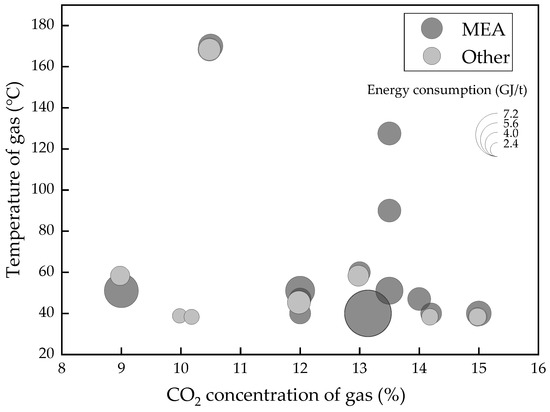
Figure 1.
Energy consumption of MEA or blends of large scales CCS projects.

Table 2.
Energy consumption data of large scales CCS projects.
Generally, there are two different kinds of models that are applied to energy analysis of the CCS process. The first type of model, such as the mixed gas separation model, as a tool for separation theory, was formed in the 1940s. It focuses only on the state of the gas before and after separation, thereby calculating the minimum work of separation, which provides a simplified analysis method. House et al. [61] applied the separation model on post combustion CCS and derived an analytic relationship for the energy penalty from the thermodynamics. Douglas et al. [62] examined the relationship between the minimum work of separation and the “separative work” from the theory stage and analyzed their differences in numerical values on specific carbon capture scenarios. However, such a black box model is too idealistic, without the combination of the specific process and operating condition, and cannot effectively guide engineering technology.
The second type of model is mainly used for the simulation of the carbon capture process, such as the widely used equilibrium model and the rate-based model. The equilibrium model uses the basic MESH equilibrium equation assumption, which stipulates that each stage is in thermodynamic equilibrium and chemical reaction equilibrium [63,64]. Although there is a good match between the simulation results and the experimental results in the temperature and pressure of columns, it also has a drawback, which requires re-implementation of the comprehensive design parameters. Therefore, this kind of process model, just like the experiment method, adjusts the operating parameters to adjust the CO2 removal result and energy consumption [65]. The specific calculation process is complicated and time-consuming and cannot grasp the common problems of this kind of technology thoroughly. The rate-based model, although in some cases, has better accuracy results than the equilibrium model, has good predictions for the range of temperature bulges in the column [66,67], but it also has similar defects.
Compared with the previous work [65], this paper aims to develop the thermodynamic cycle, which will be constructed from the ideal cycle to the actual cycle, to evaluate the energy performance of the amine-based absorption process and the lowest regeneration heat, through an example using the benchmark solvent (MEA), shown in Figure 2. COPCO2, a new assessment indicator, is proposed firstly, which is used to estimate the highest efficiency of energy conversion of the CCS technologies through the comparison of the input heat and Gibbs free energy change in a thermodynamic cycle system. In addition, the second-law efficiency is applied to evaluate the thermodynamic perfection, which makes the assessment framework more complete and reasonable.
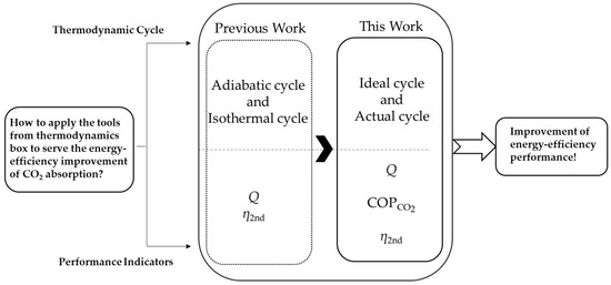
Figure 2.
Comparison of thermodynamic frameworks of previous works and this work.
2. Methodology
2.1. Framework of Thermodynamic Research
Thermodynamic, as a mature, self-consistent theory, could be applied as a powerful tool to access the energy-efficient performance of an innovative energy system. Taking the most commonly applied MEA absorption as an example, the thermodynamic cycle, which is used to provide an energy profile of a complicated energy system, should be based on the properties of the MEA solution. Moreover, the absorption and desorption process should be designed reasonably, then multiple processes are connected to form a cycle. Finally, the energy-efficient analysis is performed based on the developed cycle. In addition, performance indicators, which are developed based on thermodynamics, such as COP or perfection, could provide valuable insights on exactly how the energy-efficient performance of such a system could be. This paper provides a new method to analyze the energy conversion efficiency of CCS technologies, as shown in Figure 3. The chemical potential of CO2 is enhanced by the input heat, changing from the low CO2 concentration state, μ1, to the high CO2 concentration state, μ2, through an amine-based absorption cycle. The ratio of the Gibbs free energy change of the CO2 gas to the input heat in the cycle means the energy conversion efficiency.
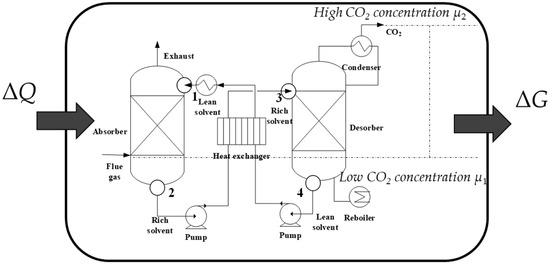
Figure 3.
The new concept of energy-efficiency performance of an amine-based absorption cycle.
2.2. Thermodynamic Cycle Construction
2.2.1. Thermodynamic Properties
• Isothermal Equilibrium Curves
Vaper–liquid equilibrium (VLE) data is vital to the study of absorption and desorption processes, which determines the performance of the CO2 removal effect. Many studies have measured the VLE data of MEA solution at different temperatures and pressures. This study, according to the empirical model from [68], used a ternary aqueous solution to manifest the isothermal equilibrium curves of 30 wt% MEA solution. The equilibrium partial pressure of CO2 correlates with the temperature and CO2 loading, given by Equation (1):
where T is the temperature in K; P is the CO2 partial pressure in Pa; and α is the CO2 loading in mol (CO2)/mol (MEA). This empirical equation could be applied for such a state, where the temperature was between 313.15 and 423.15 K. The partial pressure of water in the stripping process was estimated by the Antoine equation corresponding to the water saturated vapor pressure, as shown in Equation (2) [69]:
where is the saturated vapor pressure in Pa; xH2O is the molar fraction of 30 wt% MEA solution; and T is the temperature in K.
• Specific Heat Capacity
In the heating process, the most relevant parameter is the specific heat capacity, Cp, in kJ/kg°C. Cp is a function of the temperature shown in Equation (3), obtained from the Aspen Plus V 8.8 software, and using the E-NRTL model to calculate:
• Heat of the Absorption (ΔHabs)
The heat of absorption accounts for the greatest part of energy consumption in the regeneration process. When it comes to the energy consumption, there is an assumption that the value of absorption heat equals desorption. ΔHabs (kJ/mol CO2) varies greatly with the CO2 loading change and is a correlation given by Equation (4) in [68]:
2.2.2. Processes
A classical chemical absorption process should be divided into a four-step process, including absorption, pre-heating, desorption, and cooling. Firstly, the handled flue gas gets into the capture system, and is absorbed by MEA solvent in the absorber (1–2). Then, the rich solvent (high CO2-loading) will be pre-heated by the heater (2–3). Then, the rich solvent enters the desorber to release CO2, where plenty of steam is produced by the reboiler (3–4). Finally, the lean solvent (low CO2-loading) is cooled to the initial temperature (4–1).
2.2.3. Construction from the Ideal Cycle to the Actual Cycle
An ideal four-step chemical amine-based cycle is drawn in an isothermal equilibrium curves diagram as given in Figure 4. Before the configuration, there are some assumptions to simplify the ideal cycle:
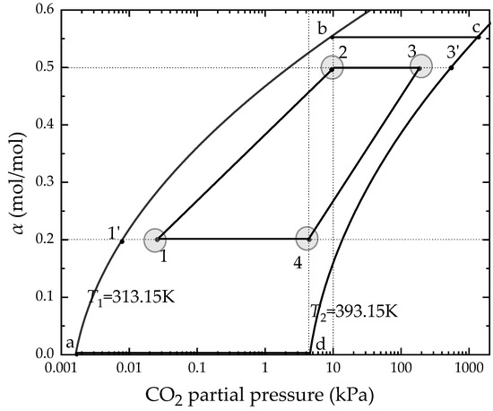
Figure 4.
The state points of thermodynamic cycle construction in MEA solution.
- The absorption and the desorption are set to an isothermal process.
- During the pre-heating and cooling process, the CO2 loading remains unchanged, that is, no CO2 desorption occurs.
- The absorption and the desorption process are in a gas–liquid equilibrium state.
- All kinds of heat loss in the cycle are not considered.
- The solution does not react with other types of gases in the flue gas except CO2, and the flue gas is assumed to be an ideal gas.
Based on the above assumptions, the ideal four-step chemical amine-based cycle was established as follows:
Step 1(a–b): The process is an isothermal absorption process, CO2 is absorbed, and the absorption process can be regarded as slowly reaching the equilibrium state, point b, along the gas–liquid isothermal equilibrium line. The determination of the state point, b, is determined by the concentration of CO2 in the flue gas, that is, by the carbon source. For example, the flue gas pressure is set at an atmospheric pressure of 101 kPa and the CO2 concentration is 10%, then the state point b corresponds to a CO2 partial pressure of 10.1 kPa, which is according to Dalton’s partial pressure law.
Step 2(b–c): The process is a pre-heating process in which the rich solvent is heated up by the heater, and no CO2 desorption occurs, that is, CO2 loading remains unchanged.
Step 3(c–d): The desorption process, in which a large amount of water vapor is generated by the reboiler in the process, resulting in a decrease in the partial pressure of CO2, and the CO2 in the liquid phase is desorbed along with the isothermal equilibrium line.
Step 4(d–a): The cooling process, in which the lean solvent is cooled by the condenser, returning to the state point a, and starting a new cycle.
As shown in Figure 3, the ideal cycle implies the reaction time is infinitely long and the performance of the absorbent is too ideal. At the same time, it indicates the ideal energy efficiency that the actual cycle can never reach, which is also not easy to compare with other models. Therefore, combined with the actual performance of the MEA solution and other practical constraints, the lean and rich solvent loading were set to 0.2 mol/mol and 0.50 mol/mol, respectively. Within the constraints of the carbon source and carbon sink, this ensures the state points 2 and 4, the driving force, Rabs and Rdes, and a condition parameter will be used to describe the how close the actual partial pressure is with the equilibrium partial pressure in the absorption and desorption process, which are defined as Equation (5) and Equation (6):
where Rabs and Rdes are the partial pressure ratios for absorption and desorption; and are the equilibrium CO2 partial pressure of lean and rich solvent; and P1 and P3 are the CO2 partial pressure of the inlet of the absorber and the inlet of the desorber.
Then, a new four-step chemical amine-based cycle, 1-2-3-4-1, a close match with the actual cycle, is formed.
2.3. Performance Indicators
Thermodynamics has proper analysis tools for efficiency assessment and improvement. The intuitive energy consumption, energy conversion efficiency, and the second-law efficiency are shown in Table 3.

Table 3.
Thermodynamic evaluation parameters for CCS.
2.3.1. Regeneration Heat
Regeneration heat is the most important part of the chemical absorption method. The total regeneration heat, Qre, can be divided into three parts [70]: Sensible heat, Qsens, for solution heating; absorption heat, Qabs, for the reaction process, and latent heat, Qvap, for generating stripping steam as shown in Equation (7) to Equation (11):
where ms is the mass flow rate of the solution in kg/sec; Tlean,end is the temperature of the lean solvent entering the desorber in K; q is the mass flow rate of captured CO2 in kg/sec; η is the capture rate; XCO2 is the concentration of CO2 in the flue gas; F is the molar flow rate of the flue gas in mol/sec; xsolv is the molar fraction of the solvent; and Msol is the molar mass of the solution; Δα is the CO2 capacity in mol/mol.
where α is the CO2 loading of the corresponding states in mol/mol; MCO2 is the molar mass of CO2.
where and are the equilibrium pressure of H2O and CO2 in the desorber; is the molar fraction of water; and Hvap is the latent heat of vaporization of water, Hvap = 41 kJ/mol.
2.3.2. COPCO2
The concept of COP was first used in refrigeration and heat pumps, which represents the ratio of the released cooling (heat) of the chiller (heat pump) to its net input energy. Using COP for energy efficiency analysis of refrigeration (heat pump) units, it can intuitively describe the energy conversion efficiency, and has a clear meaning in improving energy efficiency and reducing energy consumption. For this new cycle system that brings the Gibbs free energy change of gas caused by the driving work or heat, the traditional thermodynamic assessment indicators cannot evaluate its effect in energy conversion efficiency well. Then, based on the meaning of income and cost, expanding its application to CCS technologies is a key point of this paper. Then, COPCO2, a new assessment parameter, is introduced from the meaning and expression. In the beginning, the environmental model proposed by J. Szargut [71] should be introduced to calculate the chemical exergy of the substance. For example, at an ambient temperature of 298.15 K, an ambient pressure of P = 0.101325 MPa, and a CO2 concentration of 0.0004% in the ambient atmosphere, as long as the gas has a higher concentration or temperature, thus, it possesses chemical exergy. Figure 5 shows the description of the physical meaning of COPCO2. Based on the carbon pump theory [72], a feed gas with a low concentration of CO2, which can be a combustion flue gas, through the carbon pump turns into a high CO2 concentration product gas, gaining an increase of the chemical energy. The ratio of the increase in chemical energy to the input heat is the value of COPCO2. The expression of COPCO2 is shown in Equation (12) and Equation (13) is the fractional molar Gibbs free energy of each component of the ideal gas:
where ΔG′ is the Gibbs free energy change from the standard state, G, to a middle state, G′, which is an isothermal and isobaric process; ΔH1 is the metamorphosis from state G′ to state G1, which is an isoconcentration process; Wmin is the minimum separation work and has been discussed in many references, such as [61,62]; here Wmin = − G1; and ΔH2 is the metamorphosis from state G1 to state , which is an isothermal and isobaric process too.
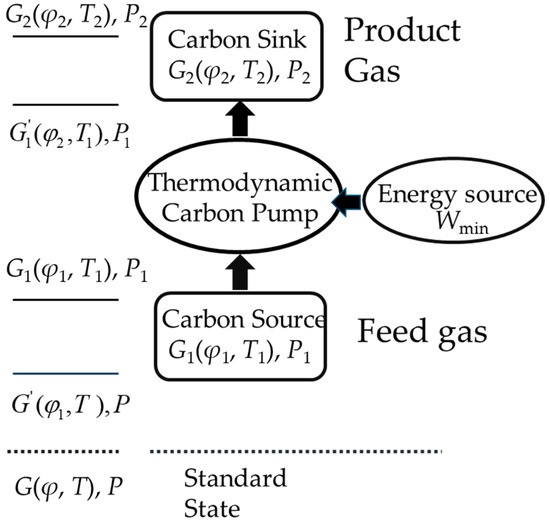
Figure 5.
Concept and expression of COPCO2.
2.3.3. The Second-Law Efficiency
The second-law efficiency is the ratio of the minimum separation work, Wmin, to the exergy of the system of the actual process as shown in Equation. (14), which has a certain guiding significance to engineering:
where WP is the electric energy consumed by the carbon capture process, mainly pump work, which accounts for a small proportion compared with the regenerative heat; Qc is the heat required for cooling, whose value could approximately equal Qsens + Qvap, provided by cooling water; T0 is the environment temperature, 298.15 K; TH is the heat source temperature set to the desorption temperature; and TL is the cold source temperature, where the cooling water temperature is usually equal to T0.
3. Results and Discussion
Based on the thermodynamic cycle constructed in Section 2.2, the energy performance was analyzed with the representative parameters, and the regeneration heat was compared with the equilibrium model, the detailed information of which can be seen in Table 4. The following cases are based on Rabs = 100 and the pinch temperature of the heat exchanger was 10 K.

Table 4.
Information of the equilibrium model.
3.1. Effect of the Ratio of Liquid:Gas (L/G)
The liquid:gas ratio is an important parameter for the absorption effect of the absorption process and the energy consumption required for the desorption process. It is generally believed that the absorption effect is better when the liquid:gas ratio is larger, but at the same time, the energy consumption of the solution regeneration process will increase. It is extremely important to select a reasonable liquid:gas ratio for the carbon capture process. Figure 6 and Figure 7 show the effect of L/G for the thermodynamic cycle and equilibrium model. L/G varies from 2.2 to 3, and both thermodynamic cycle and equilibrium model show a similar trend. Qsens and Qvap increase lightly and Qabs decreases, then the best L/G is in the actual carbon capture process. The value ranges from 2.84 to 2.82 GJ/t, and then it stars to increase up to 2.88 GJ/t when L/G varies from 2.2 to 3. The difference is greater in the equilibrium model, which ranges from 4.15 to 3.99 GJ/t, and then to 4.22 GJ/t.
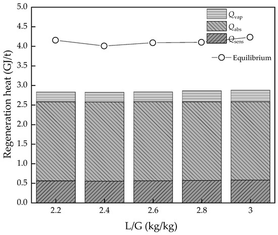
Figure 6.
The regeneration heat changes with L/G value variation.
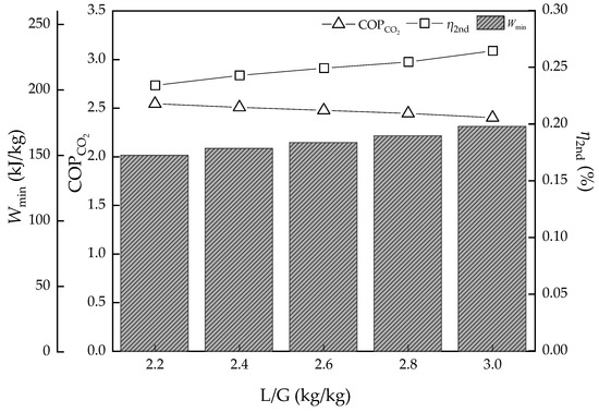
Figure 7.
The energy efficiency performance with L/G value variation.
The effect to Wmin, COPCO2, and η2nd is acting on the change of the capture ratio. With the increase of L/G, the capture ratio should be higher, then causes the Wmin to increase, which increases from 150.0 to 172.2 kJ/kg. The COPCO2, however, representing the energy conversion efficiency, decreases from 2.54 to 2.40 and means it is harder for work or heat transformation to the chemical energy of CO2 with the CO2 removal ratio increasing. In another point, η2nd rises from 23.4% to 26.4% with Wmin increasing, which means the room for improvement of the energy performance of the cycle becomes less. There is another factor that should be taken into account, which is that the L/G increase will bring extra pump work and needs an increase in some degree in the actual situation, which is also bad for a hole capture system.
3.2. Effect of CO2 Concentration of Gas
The concentration of CO2 in the flue gas varies, especially in different power plants which use different coal and operating equipment or different industrial senses. This is a key parameter in the input of the CCS system and Figure 8 and Figure 9 show the effect of variable CO2 concentrations of gas from 8% to 16%, which is suitable for the component of flue gas of coal-fired power plants.
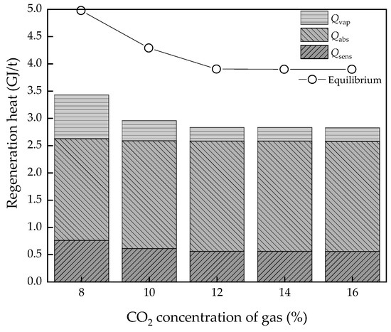
Figure 8.
The regeneration heat changes with the CO2 concentration variation.
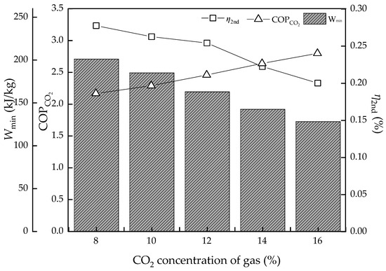
Figure 9.
The energy efficiency performance with the CO2 concentration variation.
At low concentrations, the energy consumption is apparently high both in the thermodynamic cycle and equilibrium model at 3.43 and 4.97 GJ/t, respectively, which may be similar to the effect a high L/G brings. Then, as the CO2 concentration increases, the regeneration heat declines sharply. However, it has a limitation as when the concentration is higher than the absorption capacity for a certain L/G value, the regeneration heat will not continue to decline. The lowest value is 2.82 and 3.89 GJ/t, respectively. On the other hand, when it comes to the energy conversion efficiency, the higher CO2 concentration is good news. The Wmin decreases from 201.1 to 128.2 kJ/kg continuously and COPCO2 continuously increase to 2.80. The η2nd has a similar trend with Wmin, which decreases from 27.8% to 20.0%, with lower values indicating more room for improvement of energy performance.
In summary, the higher the CO2 concentration, the higher the result of energy conversion. However, the actual solvent could not achieve such an ideal level and the existing technological process of absorption is also a limitation, which hinders the energy performance.
3.3. Effect of Desorption Temperature
The desorption temperature is an important factor of solvent properties and operating conditions. Figure 10 and Figure 11 show the result of the energy performance with different desorption temperatures. Attention should be given to the desorption temperature as the final stage temperature in the equilibrium model. The Qsens and Qabs have a slight increase, while the Qvap decreases due to the PCO2 growth. Then, the regeneration heat of the thermodynamic method and equilibrium model both have a growth trend and the equilibrium model is more obvious from 3.75 to 4.32 GJ/t, while the thermodynamic cycle is from 2.82 to 2.85 GJ/t in the ideal condition. The COPCO2 and η2nd both have a decreasing trend, but it is not obvious, from 2.48% to 2.43% and from 26.1% to 24.4%, respectively. Compared to the effect of the thermodynamic properties of MEA solvents, such as thermal degradation, the temperature change of desorption has little influence on the energy performance in ideal conditions, but in actual sense, the heat loss of every part will be greater.
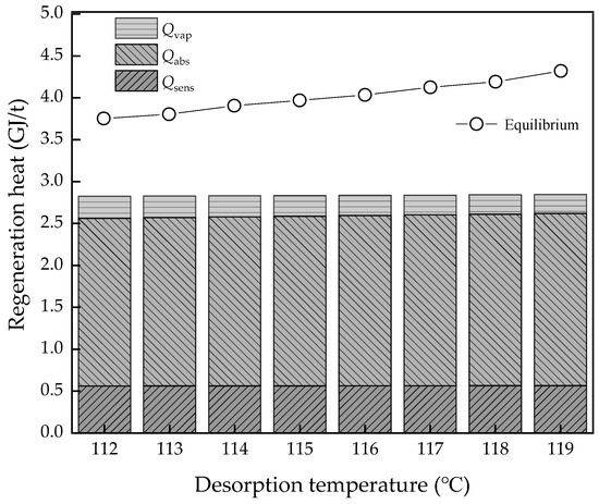
Figure 10.
The regeneration heat changes with the desorption temperature variation.
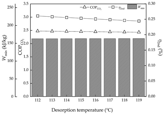
Figure 11.
The energy efficiency performance with the desorption temperature variation.
3.4. Effect of Rdes and Pinch Temperature of the Heat Exchanger
The desorption driving force, Rdes, is the degree of closeness of the actual process to the ideal thermodynamic equilibrium process. The ideal condition (Rdes = 1) has the lowest energy consumption of Qvap, which was discussed above. Figure 12 shows a validation of the desorption temperature, T3, with different Rdes. The Qvap grows rapidly and the gap is greater the more the Rdes value increases. The difference of Qvap changes from 1.31 to 1.13 GJ/t (Rdes = 5), while from 0.263 to 0.227 GJ/t (Rdes = 1). The effect of the desorption temperature is magnified, but the energy consumption is also higher. Though it is limited by the existing technical means and specific operating conditions, the lower Rdes has better energy performance.
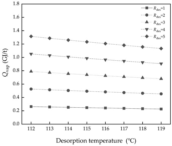
Figure 12.
The difference of Qvap with desorption temperature variation in different Rdes.
The pinch temperature of the heat exchanger, ΔTheat-ex, is a parameter involving the cost of heat exchanger equipment and the placement space. Certainly, better performance of the heat exchanger brings lower Qsens and lower heat loss. As shown in Figure 13, when L/G = 2.4, ΔTheat-ex changes from 5 to 25 K, and the Qsens climbs from 0.28 to 1.38 GJ/t, but it is a compromise, combined with others factor to decide.
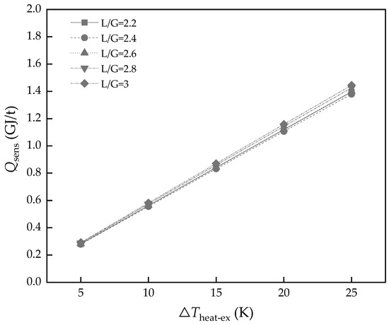
Figure 13.
The energy consumption of Qsens with different heat exchanger performances.
4. Conclusions
This paper aimed to develop a kind of thermodynamic cycle for amine-based chemical absorption of CCS to assess the lowest regeneration heat and energy efficiency. Based on the cycle, three thermodynamic assessment indicators were used to evaluate the energy performance and the regeneration heat was compared with the equilibrium model. The following results can be concluded:
- A new indicator, COPCO2, was proposed firstly, which would be integrated into the current assessment framework of CO2 absorption systems to be more complete.
- As for 30 wt% MEA solvent, the lowest regeneration heat was 2.82 GJ/t when Rdes = 1 and ΔTheat-ex = 10 K and the highest energy conversion efficiency was 2.80 in these cases.
- The L/G had the best value, as too high and too low are both bad for energy consumption of regeneration heat. However, for potential energy efficiency improvement, the lower the L/G value, the better, on the assumption that the solvent could achieve the goal of the removal rate. As for the CO2 concentration of flue gas, the higher the value, the better energy performance and efficiency. However, real performance is limited by the solvent properties, which may not achieve the ideal conditions; the lowest regeneration heat was about 2.82 and 3.89 GJ/t, respectively, while the COPCO2 continued to increase. The desorption temperature was not a sensitive parameter to energy performance in an ideal condition. However, in the actual situation, the higher the temperature, the higher the heat loss.
- The operating parameters, Rdes and ΔTheating-ex, were a compromise between cost and performance. The better performance of the heat exchanger will bring a lot of energy saving in Qsens, which decreased from 1.38 to 0.28 GJ/t when ΔTheating-ex varied from 25 to 5 K in L/G = 2.4.
Finally, this thermodynamic cycle is expected to be used as an analysis tool for the energy efficiency performance of amine-based chemical absorption; however, more aspects, like thermal degradation, viscosity, and so on, should be considered and need further study.
Author Contributions
Conceptualization, Y.X.; Data curation, S.L.; Methodology, L.Z. and X.Y.; Software, J.F. and Y.L.; Writing—original draft, Y.X.; Writing—review amd editing, S.D.
Funding
This research was funded by China National Natural Science Funds, grant number 51876134, by Research Plan of Science and Technology of Tianjin City, grant number 18YDYGHZ00090 and by Tianjin Talent Development Special Support Program for High-Level Innovation and Entrepreneurship team.
Conflicts of Interest
The authors declare no conflict of interest.
Nomenclature
| Symbols | sol | MEA solution | |
| P | Pressure | Greek letters | |
| T | Temperature | α | CO2 loading |
| ΔHabs | Heat of CO2 absorption | Δα | CO2 capacity |
| Hvap | Heat of water evaporation | η2nd | Second law efficiency |
| Cp | Specific heat of solution | η | Capture rate |
| Q | Energy consumption | Acronym | |
| x | Molar fraction | CCS | Carbon capture |
| R | Partial pressure ratio | L/G | Ratio of liquid-gas |
| M | Molar mass | ILs | Ionic liquids |
| XCO2 | Concentration of CO2 in flue gas | VLE | Vaper-Liquid-Equilibrium |
| F | Molar flow rate of flue gas | MEA | Monoethanolamine |
| ms | Mass flow rate of solution | MDEA | Methyldiethanolamine |
| q | Mass flow rate of captured CO2 | PZ | Piperazine |
| COPCO2 | Energy conversion efficiency of CCS | AMP | 2-amino-2-methyl-1-propanol |
| Subscripts | MAPA | N-methyl-1,3-propane-diamine | |
| abs | Absorption | DEEA | 2-(diethylamino)-ethanol |
| des | Desorption | AEEA | 2-((2-aminoethyl) amino) ethanol |
| sen | Sensible | TETA | Triethylenetetramine |
| vap | Water evaporation | DEAPD | 3-(Diethylamino)-1,2-propanediol |
| re | Regeneration | TMPDA | Tetramethyl-1,3-propanediamine |
| solv | MEA solvent | DMCA | N, N-dimethylcyclohexylamine |
References
- A Daily Record of Atmospheric Carbon Dioxide from Scripps Institution of Oceanography at UC San Diego. Available online: https://scripps.ucsd.edu/programs/keelingcurve/ (accessed on 13 May 2019).
- Rizvi, R.H.; Newaj, R.; Chaturvedi, O.P.; Prasad, R.; Handa, A.K.; Alam, B. Carbon sequestration and CO2 absorption by agroforestry systems: An assessment for Central Plateau and Hill region of India. J. Earth Syst. Sci. 2019, 128, 56. [Google Scholar] [CrossRef]
- Aerenson, T.; Tebaldi, C.; Sanderson, B.; Lamarque, J.F. Changes in a suite of indicators of extreme temperature and precipitation under 1.5 and 2 degrees warming. Environ. Res. Lett. 2018, 13, 035009. [Google Scholar] [CrossRef]
- Special Report on Global Warming of 1.5 °C (Report). Incheon, South Korea; Intergovernmental Panel on Climate Change (IPCC): Geneva, Switzerland, 7 October 2018. Available online: https://www.ipcc.ch/sr15/ (accessed on 13 May 2019).
- International Energy Agency. Energy Technology Perspectives; International Energy Agency: Paris, France, 2017; Available online: https://webstore.iea.org/energy-technology-perspectives-2017 (accessed on 13 May 2019).
- Kanniche, M.; Le Moullec, Y.; Authier, O.; Hagi, H.; Bontemps, D.; Neveux, T.; Louis-Louisy, M. Up-to-date CO2 Capture in Thermal Power Plants. Energy Procedia 2017, 114, 95–103. [Google Scholar] [CrossRef]
- Mantripragada, H.C.; Zhai, H.; Rubin, E.S. Boundary Dam or Petra Nova–Which is a better model for CCS energy supply? Int. J. Greenh Gas Control 2019, 82, 59–68. [Google Scholar] [CrossRef]
- Zhao, R.; Shuai, D.; Li, Z.; Liu, Y.; Tan, Y. Energy-saving pathway exploration of CCS integrated with solar energy: Literature research and comparative analysis. Energy Convers. Manag. 2015, 102, 66–80. [Google Scholar] [CrossRef]
- Idem, R.; Wilson, M.; Tontiwachwuthikul, P.; Chakma, A.; Veawab, A.; Aroonwilas, A.; Gelowitz, D. Pilot Plant Studies of the CO2 Capture Performance of Aqueous MEA and Mixed MEA/MDEA Solvents at the University of Regina CO2 Capture Technology Development Plant and the Boundary Dam CO2 Capture Demonstration Plant. Ind. Eng. Chem. Res. 2006, 45, 2414–2420. [Google Scholar] [CrossRef]
- Li, X.; Wang, S.; Chen, C. Experimental Study of Energy Requirement of CO2 Desorption from Rich Solvent. Energy Procedia 2013, 37, 1836–1843. [Google Scholar] [CrossRef]
- Sakwattanapong, R.; Aroonwilas, A.A.; Veawab, A. Behavior of Reboiler Heat Duty for CO2 Capture Plants Using Regenerable Single and Blended Alkanolamines. Ind. Eng. Chem. Res. 2005, 44, 4465–4473. [Google Scholar] [CrossRef]
- Artanto, Y.; Jansen, J.; Pearson, P.; Do, T.; Cottrell, A.; Meuleman, E.; Feron, P. Performance of MEA and amine-blends in the CSIRO PCC pilot plant at Loy Yang Power in Australia. Fuel 2012, 101, 264–275. [Google Scholar] [CrossRef]
- Zhao, B.; Liu, F.; Cui, Z.; Liu, C.; Yue, H.; Tang, S.; Liu, Y.; Lu, H.; Liang, B. Enhancing the energetic efficiency of MDEA/PZ-based CO2 capture technology for a 650 MW power plant: Process improvement. Appl. Energy 2016, 185, 362–375. [Google Scholar] [CrossRef]
- Wai, S.K.; Nwaoha, C.; Saiwan, C.; Idem, R.; Supap, T. Absorption heat, solubility, absorption and desorption rates, cyclic capacity, heat duty, and absorption kinetic modeling of AMP–DETA blend for post–combustion CO2 capture. Sep. Purif. Technol. 2018, 194, 89–95. [Google Scholar] [CrossRef]
- Mangalapally, H.P.; Hasse, H. Pilot plant study of two new solvents for post combustion carbon dioxide capture by reactive absorption and comparison to monoethanolamine. Chem. Eng. Sci. 2011, 66, 5512–5522. [Google Scholar] [CrossRef]
- Rabensteiner, M.; Kinger, G.; Koller, M.; Hochenauer, C. Pilot plant study of aqueous solution of piperazine activated 2-amino-2-methyl-1-propanol for post combustion carbon dioxide capture. Int. J. Greenh. Gas. Control 2016, 51, 106–117. [Google Scholar] [CrossRef]
- Yang, J.; Yu, X.; Yan, J.; Tu, S.T. CO2 capture using amine solution mixed with ionic liquid. Ind. Eng. Chem. Res. 2014, 53, 2790–2799. [Google Scholar] [CrossRef]
- Bernard, F.L.; Dalla Vecchia, F.; Rojas, M.F.; Ligabue, R.; Vieira, M.O.; Costa, E.M.; Chaban, V.V.; Einloft, S. Anticorrosion Protection by Amine-Ionic Liquid Mixtures: Experiments and Simulations. J. Chem. Eng. Data 2016, 61, 1803–1810. [Google Scholar] [CrossRef]
- Akinola, T.E.; Oko, E.; Wang, M. Study of CO2 removal in natural gas process using mixture of ionic liquid and MEA through process simulation. Fuel 2019, 236, 135–146. [Google Scholar] [CrossRef]
- Zacchello, B.; Oko, E.; Wang, M.; Fethi, A. Process simulation and analysis of carbon capture with an aqueous mixture of ionic liquid and monoethanolamine solvent. Int. J. Coal Sci. Technol. 2017, 4, 25–32. [Google Scholar] [CrossRef]
- Ying, H.; Zhang, X.; Xin, Z.; Dong, H.; Zhang, S. Thermodynamic Modeling and Assessment of Ionic Liquid-Based CO2 Capture Processes. Ind. Eng. Chem. Res. 2014, 53, 11805–11817. [Google Scholar]
- Mobley, P.D.; Rayer, A.V.; Tanthana, J.; Gohndrone, T.R.; Soukri, M.; Coleman, L.J.; Lail, M. CO2 Capture Using Fluorinated Hydrophobic Solvents. Ind. Eng. Chem. Res. 2017, 56, 11958–11966. [Google Scholar] [CrossRef]
- Yu, Y.S.; Lu, H.F.; Zhang, T.T.; Zhang, Z.X.; Wang, G.X.; Rudolph, V. Determining the Performance of an Efficient Nonaqueous CO2 Capture Process at Desorption Temperatures below 373 K. Ind. Eng. Chem. Res. 2013, 52, 12622–12634. [Google Scholar] [CrossRef]
- Guo, H.; Li, C.; Shi, X.; Li, H.; Shen, S. Nonaqueous amine-based absorbents for energy efficient CO2 capture. Appl. Energy 2019, 239, 725–734. [Google Scholar] [CrossRef]
- Zhu, K.; Lu, H.; Liu, C.; Wu, K.; Jiang, W.; Cheng, J.; Tang, S.; Yue, H.; Liu, Y.; Liang, B. Investigation on the Phase-Change Absorbent System MEA + Solvent A (SA) + H2O Used for the CO2 Capture from Flue Gas. Ind. Eng. Chem. Res. 2019, 58, 3811–3821. [Google Scholar] [CrossRef]
- Zhang, W.; Jin, X.; Tu, W.; Ma, Q.; Mao, M.; Cui, C. Development of MEA-based CO2 phase change absorbent. Appl. Energy 2017, 195, 316–323. [Google Scholar] [CrossRef]
- Zhang, J.; Yu, Q.; Agar, D.W. Improvement of Lipophilic-Amine-based Thermomorphic Biphasic Solvent for Energy-Efficient Carbon Capture. Energy Procedia 2012, 23, 92–101. [Google Scholar] [CrossRef]
- Pinto, D.D.D.; Knuutila, H.; Fytianos, G.; Haugen, G.; Mejdell, T.; Svendsen, H.F. CO2 post combustion capture with a phase change solvent. Pilot plant campaign. Int. J. Greenh. Gas Control 2014, 31, 153–164. [Google Scholar] [CrossRef]
- Shen, Y.; Jiang, C.; Zhang, S.; Chen, J.; Wang, L.; Chen, J. Biphasic solvent for CO2 capture: Amine property-performance and heat duty relationship. Appl. Energy 2018, 230, 726–733. [Google Scholar] [CrossRef]
- Liu, F.; Fang, M.; Dong, W.; Wang, T.; Xia, Z.; Wang, Q.; Luo, Z. Carbon dioxide absorption in aqueous alkanolamine blends for biphasic solvents screening and evaluation. Appl. Energy 2019, 233–234, 468–477. [Google Scholar] [CrossRef]
- Zhang, S.; Shen, Y.; Shao, P.; Chen, J.; Wang, L. Kinetics, Thermodynamics, and Mechanism of a Novel Biphasic Solvent for CO2 Capture from Flue Gas. Environ. Sci. Technol. 2018, 52, 3660–3668. [Google Scholar] [CrossRef]
- Cuccia, L.; Dugay, J.; Bontemps, D.; Louis-Louisy, M.; Morand, T.; Kanniche, M.; Bellosta, V.; Vial, J. Monitoring of the blend monoethanolamine/methyldiethanolamine/water for post-combustion CO2 capture. Int. J. Greenh. Gas Control 2019, 80, 43–53. [Google Scholar] [CrossRef]
- Gladis, A.; Lomholdt, N.F.; Fosbøl, P.L.; Woodley, J.M.; von Solms, N. Pilot scale absorption experiments with carbonic anhydrase-enhanced MDEA-Benchmarking with 30 wt% MEA. Int. J. Greenh. Gas Control 2019, 82, 69–85. [Google Scholar] [CrossRef]
- Hadri, N.E.; Dang, V.Q.; Goetheer, E.L.V.; Zahra, M.R.M.A. Aqueous amine solution characterization for post-combustion CO2 capture process. Appl. Energy 2016, 185, 1433–1449. [Google Scholar] [CrossRef]
- Bougie, F.; Iliuta, M.C. Sterically Hindered Amine-Based Absorbents for the Removal of CO2 from Gas Streams. J. Chem. Eng. Data 2012, 57, 635–669. [Google Scholar] [CrossRef]
- Ahmady, A.; Hashim, M.A.; Aroua, M.K. Experimental Investigation on the Solubility and Initial Rate of Absorption of CO2 in Aqueous Mixtures of Methyldiethanolamine with the Ionic Liquid 1-Butyl-3-methylimidazolium Tetrafluoroborate. J. Chem. Eng. Data 2010, 55, 5733–5738. [Google Scholar] [CrossRef]
- Haider, M.B.; Hussain, Z.; Kumar, R. CO2 absorption and kinetic study in ionic liquid amine blends. J. Mol. Liq. 2016, 224, 1025–1031. [Google Scholar] [CrossRef]
- Kumar, S.; Cho, J.H.; Moon, I. Ionic liquid-amine blends and CO2 BOLs: Prospective solvents for natural gas sweetening and CO2 capture technology-A review. Int. J. Greenh. Gas Control 2014, 20, 87–116. [Google Scholar] [CrossRef]
- Gao, J.; Cao, L.; Dong, H.; Zhang, X.; Zhang, S. Ionic liquids tailored amine aqueous solution for pre-combustion CO2 capture: Role of imidazolium-based ionic liquids. Appl. Energy 2015, 154, 771–780. [Google Scholar] [CrossRef]
- Camper, D.; Bara, J.E.; Gin, D.L.; Noble, R.D. Room-temperature ionic liquid-amine solutions: Tunable solvents for efficient and reversible capture of CO2. Ind. Eng. Chem. Res. 2008, 47, 8496–8498. [Google Scholar] [CrossRef]
- Zhai, H.; Rubin, E.S. Systems Analysis of Ionic Liquids for Post-combustion CO2 Capture at Coal-fired Power Plants. Energy Procedia 2014, 63, 1321–1328. [Google Scholar] [CrossRef]
- Ramdin, M.; De Loos, T.W.; Vlugt, T.J.H. State-of-the-art of CO2 capture with ionic liquids. Ind. Eng. Chem. Res. 2012, 51, 8149–8177. [Google Scholar] [CrossRef]
- Chao, G.; Chen, S.; Zhang, Y.; Wang, G. Solubility of CO2 in Nonaqueous Absorption System of 2-(2-Aminoethylamine) ethanol + Benzyl Alcohol. J. Chem. Eng. Data 2014, 59, 1796–1801. [Google Scholar]
- Dinda, S.; Goud, V.V.; Patwardhan, A.V.; Pradhan, N.C. Kinetics of reactive absorption of carbon dioxide with solutions of 1,6-hexamethylenediamine in polar protic solvents. Sep. Purif. Technol. 2010, 75, 1–7. [Google Scholar] [CrossRef]
- Chen, S.; Hu, G.; Smith, K.H.; Mumford, K.A.; Zhang, Y.; Stevens, G.W. Kinetics of CO2 Absorption in an Ethylethanolamine Based Solution. Ind. Eng. Chem. Res. 2017, 56, 12305–12315. [Google Scholar] [CrossRef]
- Yu, C.H.; Wu, T.W.; Tan, C.S. CO2 capture by piperazine mixed with non-aqueous solvent diethylene glycol in a rotating packed bed. Int. J. Greenh. Gas Control 2013, 19, 503–509. [Google Scholar] [CrossRef]
- Leimbrink, M.; Sandkämper, S.; Wardhaugh, L.; Maher, D.; Green, P.; Puxty, G.; Conway, W.; Bennett, R.; Botma, H.; Feron, P.; et al. Energy-efficient solvent regeneration in enzymatic reactive absorption for carbon dioxide capture. Appl. Energy 2017, 208, 263–276. [Google Scholar] [CrossRef]
- Akachuku, A.; Osei, P.A.; Decardi-Nelson, B.; Srisang, W.; Pouryousefi, F.; Ibrahim, H.; Idem, R. Experimental and kinetic study of the catalytic desorption of CO2 from CO2 -loaded monoethanolamine (MEA) and blended monoethanolamine – Methyl-diethanolamine (MEA-MDEA) solutions. Energy 2019, 179, 475–489. [Google Scholar] [CrossRef]
- Lai, Q.; Toan, S.; Assiri, M.A.; Cheng, H.; Russell, A.G.; Adidharma, H.; Radosz, M.; Fan, M. Catalyst-TiO(OH)2 could drastically reduce the energy consumption of CO2 capture. Nat. Commun. 2018, 9, 2672. [Google Scholar] [CrossRef]
- Rabensteiner, M.; Kinger, G.; Koller, M.; Hochenauer, C. Three years of working experience with different solvents at a realistic post combustion capture pilot plant. Energy Procedia 2014, 63, 1578–1584. [Google Scholar] [CrossRef]
- Stec, M.; Tatarczuk, A.; Więcław-Solny, L.; Krótki, A.; Ciązko, M.; Tokarski, S. Pilot plant results for advanced CO2 capture process using amine scrubbing at the Jaworzno II Power Plant in Poland. Fuel 2015, 151, 50–56. [Google Scholar] [CrossRef]
- Krótki, A.; Więcław-Solny, L.; Tatarczuk, A.; Stec, M.; Wilk, A.; Śpiewak, D.; Spietz, T. Laboratory Studies of Post-combustion CO2 Capture by Absorption with MEA and AMP Solvents. Arab. J. Sci. Eng. 2016, 41, 371–379. [Google Scholar] [CrossRef]
- Wiecław-Solny, L.; Tatarczuk, A.; Stec, M.; Krótki, A. Advanced CO2 capture pilot plant at tauron’s coal-fired power plant: Initial results and further opportunities. Energy Procedia 2014, 63, 6318–6322. [Google Scholar] [CrossRef]
- Knudsen, J.N.; Andersen, J.; Jensen, J.N.; Biede, O. Evaluation of process upgrades and novel solvents for the post combustion CO2 capture process in pilot-scale. Energy Procedia 2011, 4, 1558–1565. [Google Scholar] [CrossRef]
- Knudsen, J.N.; Jensen, J.N.; Vilhelmsen, P.J.; Biede, O. Experience with CO2 capture from coal flue gas in pilot-scale: Testing of different amine solvents. Energy Procedia 2009, 1, 783–790. [Google Scholar] [CrossRef]
- Moser, P.; Schmidt, S.; Sieder, G.; Garcia, H.; Stoffregen, T.; Stamatov, V. The post-combustion capture pilot plant Niederaussem-Results of the first half of the testing programme. Energy Procedia 2011, 4, 1310–1316. [Google Scholar] [CrossRef]
- Feron, P.H.; Cousins, A.; Gao, S.; Liu, L.; Wang, J.; Wang, S.; Niu, H.; Yu, H.; Li, K.; Cottrell, A. Experimental performance assessment of a mono-ethanolamine-based post-combustion CO2 capture at a coal-fired power station in China. Greenh. Gas Sci. Technol. 2017, 7, 486–499. [Google Scholar] [CrossRef]
- Mangalapally, H.P.; Hasse, H. Pilot plant study of post-combustion carbon dioxide capture by reactive absorption: Methodology, comparison of different structured packings, and comprehensive results for monoethanolamine. Chem. Eng. Res. Des. 2011, 89, 1216–1228. [Google Scholar] [CrossRef]
- Nakamura, S.; Yamanaka, Y.; Matsuyama, T.; Okuno, S.; Sato, H. IHI s amine-based CO2 capture technology for coal fired power plant. Energy Procedia 2013, 37, 1897–1903. [Google Scholar] [CrossRef]
- Vitse, F.; Baburao, B.; Dugas, R.; Czarnecki, L.; Schubert, C. Technology and pilot plant results of the advanced amine process. Energy Procedia 2011, 4, 5527–5533. [Google Scholar] [CrossRef]
- House, K.Z.; Harvey, C.F.; Aziz, M.J.; Schrag, D.P. The energy penalty of post-combustion CO2 capture storage and its implications for retrofitting the U.S. installed base. Energy Environ. Sci. 2009, 2, 193–205. [Google Scholar] [CrossRef]
- Ruthven, D.M. CO2 capture: Value functions, separative work and process economics. Chem. Eng. Sci. 2014, 114, 128–133. [Google Scholar] [CrossRef]
- Wu, Y.; Wu, F.; Hu, G.; Mirza, N.R.; Stevens, G.W.; Mumford, K.A. Modelling of a post-combustion carbon dioxide capture absorber using potassium carbonate solvent in Aspen Custom Modeller. Chin. J. Chem. Eng. 2018, 26, 2327–2336. [Google Scholar] [CrossRef]
- Mores, P.; Scenna, N.; Mussati, S. A rate based model of a packed column for CO2 absorption using aqueous monoethanolamine solution. Int. J. Greenh. Gas Control 2012, 6, 21–36. [Google Scholar] [CrossRef]
- Wang, J.; Sun, T.; Zhao, J.; Deng, S.; Li, K.; Xu, Y.; Fu, J. Thermodynamic considerations on MEA absorption: Whether thermodynamic cycle could be used as a tool for energy efficiency analysis. Energy 2019, 168, 380–392. [Google Scholar] [CrossRef]
- Simon, L.L.; Elias, Y.; Puxty, G.; Artanto, Y.; Hungerbuhler, K. Rate based modeling and validation of a carbon-dioxide pilot plant absorbtion column operating on monoethanolamine. Chem. Eng. Res. Des. 2011, 89, 1684–1692. [Google Scholar] [CrossRef]
- Kvamsdal, H.M.; Rochelle, G.T. Effects of the temperature bulge in CO2 absorption from flue gas by aqueous monoethanolamine. Ind. Eng. Chem. Res. 2008, 47, 867–875. [Google Scholar] [CrossRef]
- Qing, X. Thermodynamics of CO2 Loaded Aqueous Amines. Ph.D. Thesis, University of Texas Libraries, Austin, TX, USA, 2011. [Google Scholar]
- Xu, Q.; Rochelle, G. Total pressure and CO2 solubility at high temperature in aqueous amines. Energy Procedia 2011, 4, 117–124. [Google Scholar] [CrossRef]
- Wang, T.; Yu, W.; Le Moullec, Y.; Liu, F.; Xiong, Y.; He, H.; Lu, J.; Hsu, E.; Fang, M.; Luo, Z. Solvent regeneration by novel direct non-aqueous gas stripping process for post-combustion CO2 capture. Appl. Energy 2017, 205, 23–32. [Google Scholar] [CrossRef]
- Morris, D.R.; Szargut, J. Standard chemical exergy of some elements and compounds on the planet earth. Energy 1986, 11, 733–755. [Google Scholar] [CrossRef]
- Zhao, R.; Deng, S.; Liu, Y.; Zhao, Q.; He, J.; Zhao, L. Carbon pump: Fundamental theory and applications. Energy 2017, 119, 1131–1143. [Google Scholar] [CrossRef]
© 2019 by the authors. Licensee MDPI, Basel, Switzerland. This article is an open access article distributed under the terms and conditions of the Creative Commons Attribution (CC BY) license (http://creativecommons.org/licenses/by/4.0/).