Article

In Situ Water Electrolyzer Stack for an Electrobioreactor

1
School of Energy Systems, LUT University, P.O. Box 20, FI-53851 Lappeenranta, Finland
2
VTT Technical Research Centre of Finland Ltd., P.O. Box 1000, 02044 VTT, Espoo, Finland
*
Author to whom correspondence should be addressed.
Energies 2019, 12(10), 1904; https://doi.org/10.3390/en12101904
Submission received: 18 April 2019 / Revised: 13 May 2019 / Accepted: 15 May 2019 / Published: 18 May 2019

Abstract

:
Hydrogen-oxidizing bacteria provide a sustainable solution for microbial protein production. Renewable electricity can be used for in situ water electrolysis in an electrobioreactor. The use of cultivation medium as the electrolyte enhances the hydrogen dissolution to the medium. This paper proposes a stack structure for in situ water electrolysis to improve the productivity of the electrobioreactor. The hydrogen production rate and the energy efficiency of the prototype stack are analyzed.

1. Introduction

The intensive use of fossil fuels has resulted in the depletion of natural resources, increasing levels of greenhouse gas emissions, and undesired climate changes. The generation of electrical energy from abundant renewable energy sources, such as wind and solar energy, provides a sustainable and environmentally friendly alternative to fossil-fuel-based energy [1]. However, the intermittent nature of solar and wind energy sources requires the development of efficient and flexible methods for energy storage [2]. Moreover, in order to deal with the challenge of climate change, there is an urgent need for efficient technologies that are capable of capturing and using carbon. One emerging strategy that might significantly contribute to the transition towards a renewable energy-based economy is the microbial assimilation of carbon. This method enables the fixation of abundantly available atmospheric CO2 and its further use as a source of carbon for carbonaceous products and energy carriers by means of microorganisms [3,4,5].
Considering various microorganisms, autotrophic aerobic hydrogen-oxidizing bacteria (HOB) have been found to be among the most prospective candidates to exploit the potential of renewable energy generation. The distinctive feature of HOB is that they can be grown in a mineral medium containing low amounts of citrate as a minor source of organic carbon, using atmospheric or point source CO2 as the source of carbon along with H2 and O2, which act as the electron donor and the electron acceptor, respectively, for the production of new cellular materials [6]. The intrinsic premier product of CO2 assimilation by HOB is biomass, the content of which can be tuned to be rich in carbohydrates, proteins, or fatty acids. Thus, HOB have the potential to play a significant role in future sustainable food production systems [7].
The obtained microbial biomass is frequently referred to as a single cell protein (SCP) also known as a microbial protein (MP) because of its high crude protein content of approximately 70–75% [8]. Volova et al. [9] found that the biological value of proteins synthesized by different strains of HOB is sufficient for them to be considered as a potential protein source for human and animal nutrition. The feasibility of CO2 assimilation by HOB has recently been proven on a pilot scale within the framework of the Power-to-Protein project in Belgium. A pilot plant produces an MP with a targeted capacity of 1–2 kg per day using HOB with H2 and O2 produced by water electrolysis and CO2 and NH3 recovered from a wastewater treatment plant [10]. Polyhydroxybutyrate (PHB) is another possible bio-based product, which can be derived from CO2 assimilation by HOB [6,11]. Interestingly, PHB is a biopolymer and is considered a carbon and energy storage material in bacteria. A wide variety of important platform chemicals can be derived from PHB including thermoplastic, methyl-esterified 3-hydroxybutyrate oligomers, R-3-hydroxybutyric acid, 1,3-butandiol (BDO), crotonic acid, acetoacetic acid, and some others [12].
The low solubility of the main reactant gases H2, O2, and CO2 in the aqueous solution where the HOB cells are being suspended drastically decreases the mass transfer and overall process efficiency [12]. The highest reported average H2-to-biomass conversion efficiencies are up to 80% in continuous operation and up to 65% in the sequence batch reactor [11]. To overcome this constraint, there is increasing scientific interest in combining water electrolysis and CO2 assimilation by HOB into a single vessel, which is called a hybrid biological-inorganic (HBI) system. This provides an advantage of improved gas transfer of H2 and O2 to the liquid phase over the conventional gas fermentation process with an external supply of main reactant gases. The concept was successfully proven on a laboratory scale by Pamela A. Silver and Daniel G. Nocera’s research group. For instance, Torella et al. [13] reported a development of integrated bioelectrochemical systems in which HOB was used to convert CO2 into biomass and fuel alcohols at high efficiencies using scalable earth-abundant catalysts. In subsequent studies, Liu et al. [14] developed a hybrid water splitting-biosynthetic system based on CO-based catalysts possessing unique self-healing properties, which made it possible to achieve a CO2 reduction efficiency above 50% and a solar-to-chemical efficiency of almost 10% when coupled with the existing photovoltaic systems. A hybrid inorganic-biological system and the same biocompatible catalysts were used to fix CO2 and N2 into NH3 and a biofertilizer in the studies of [15] and for biomass synthesis from CO2 in the studies of [16].
After successful proof-of-concept of CO2 assimilation by HOB using the HBI systems, the scientific focus shifted towards the objectives of enhanced energy efficiency, product selectivity, and scaling up [17]. The development of a robust, efficient, and ergonomic reactor system designed with in situ electrolysis of the cultivation medium for the HBI process is considered one of the key research directions in this field. The main requirements for such a design are the following: (i) the system has to be biocompatible; (ii) the system must have an acceptable electrode surface-to-volume ratio, and (iii) the system components must be low cost and have long-term stability [18]. Other main limitations of the HBI systems are the low conductivity of the cultivation medium, an increase in the ohmic losses, and the current density limitations set by the microorganisms. In the traditional alkaline and proton exchange membrane (PEM) electrolyzers, the electrolytic cells are series connected to form a stack structure with a high efficiency and a compact design [19]. Thus, the electrolyzer stack structure has not been reported to be applied to HBI systems.
The purpose of this study is to develop and present a conceptual design of an electrobioreactor to enable upscaling of the HBI process to an industrial scale and to discuss the main aspects affecting the energy efficiency of the system. To reach these targets, a novel in situ water electrolyzer stack structure for an electrobioreactor is introduced to enhance the hydrogen production rate and energy efficiency of HOB cultivation. The performance of the in situ electrolyzer stack is experimentally studied. Further, the achievable energy efficiency and the volumetric hydrogen production rate are discussed based on the cell model.
This paper is organized as follows: Section 2 describes the principles of HOB production with in situ water electrolysis. The in situ water electrolyzer stack prototype is introduced and the experimental results are discussed in Section 3 and in Section 4, respectively. Finally, Section 5 concludes the paper.

2. Theory and Concept Background

To date, all reported bioelectrochemical systems (BES) have been studied at volumes ranging from 100 m L to 1 L by applying simplified electrode configurations [5,13,14,15,16]. This leads to the conclusion that the BES design technology is currently in its infancy. This section aims to provide a possible conceptual design for a scaled-up prototype for the BES by first defining the special characteristics of in situ water electrolysis and the BES, then describing the design idea, and finally, proving and testing the concept on an experimental scale.

2.1. In Situ Water Electrolysis and Electrobioreactor Characteristics

While the technical performance and energy efficiency of the electrobioreactors are crucial aspects that have to be taken into consideration in the design stage, water electrolysis can be considered one of the major phenomena that affects those criteria. The minimum thermodynamic potential required for water electrolysis, called reversible voltage, is 1.23 V under standard ambient conditions. Without auxiliary heat, the required minimum voltage is higher and is dependent on the electrolysis conditions (e.g., 1.43 V under standard ambient conditions). From the perspective of energy efficiency, the voltage driving the electrolysis should thus be kept as low as possible. The actual voltage required to drive the electrolysis is higher because of overvoltages (i.e., voltage losses) caused by the impedance between the electrodes and the activation reactions. Hence, the overall cell voltage is the sum of different overvoltages (overpotentials), as presented in the following equation:
U cell = U rev + U ohm + U act + U con ,
where U cell is the cell voltage, U rev is the reversible open circuit voltage, U ohm is the overvoltage caused by ohmic losses in the cell elements, U act is the activation overvoltage caused by electrode kinetics, and U con is the concentration overvoltage caused by the mass transport processes [20].
There are several crucial parameters that describe the water electrolysis process. First of all, the production of hydrogen can be estimated according to Faraday’s laws of electrolysis. The hydrogen production rate (N L / h ) is directly proportional to the electric charge transferred at the electrodes and can be expressed as
f H 2 = η F N cell i cell A cell z F 22.41 NL mol 3600 s h ,
where z is the number of moles of electrons transferred in the reaction (for hydrogen, z = 2), F is the Faraday constant ( 9.6485 × 10 4 C / mol ), N cell is the number of cells constituting the electrolyzer stack, i cell is the current density ( A /cm 2 ), A cell is the effective cell area (cm 2 ), and η F is the Faraday efficiency, also known as the current efficiency.
Secondly, the specific energy consumption E s ( kWh / N m 3 ) of an electrolysis process, which relates the energy consumed to produce hydrogen, can be obtained from
E s = 0 t N cell i cell A cell U cell d t 0 t f H 2 d t ,
where f H 2 is the hydrogen flow rate in N m / h 3 .
Finally, the electrolyzer stack efficiency can be calculated based on the higher heating value (HHV), which is the minimum energy required to produce hydrogen gas by a thermoneutral process. The per volume unit HHV of hydrogen gas is 3.54 kWh / N m 3 , which can be assumed to represent the energy consumption of the process with a 100% efficiency. Thus, the electrolyzer efficiency can be described by the following equation:
η E = HHV H 2 E s 100 % .
On the other hand, the particularity of the process itself is definitely yet another dominating aspect in the design development of the HBI system. Due to the fact that both H2 and O2 are important for CO2 fixation by HOB, a simplified design that does not require expensive separation of anode and cathode compartments is possible for this process. The application of an electrolyzer without a separator facilitates the operation and maintenance of the system while reducing the capital costs. Furthermore, a simplified construction eliminates the internal resistance and therefore the ohmic overpotential related to the separator. However, the main source of ohmic overpotential is the pH-neutral electrolyte with a relatively low conductivity which is typically used in HBI systems.
One notable constraint of the HBI process is the incidental formation of toxic reactive oxygen species (ROS) on the cathode side, represented by superoxide, hydrogen peroxide, and hydroxyl radicals, at and below potentials required for the H2 evolution reaction [17]. This phenomenon can be mitigated by using biocompatible ROS-resistant catalysts. For instance, a cobalt-phosphorous (CoP) alloy cathode, which kinetically favors H2 generation, was used in combination with a self-healing cobalt–phosphate anode to enhance the production rate and achieve high solar-to-fuel and solar-to-biomass energy efficiencies in the studies of [14]. Distinctive advantages of the aforementioned catalysts include (i) biocompatibility; (ii) low overpotentials required for water splitting; (iii) low cost as a result of the use of earth-abundant materials as raw materials, and (iv) ease of manufacture by electrodeposition into a variety of conventional substrate materials, such as stainless steel or nickel sheets.

2.2. Immersed Electrodes

So far, the bioelectrochemical systems for the above-mentioned microbial protein production have used simple rod or plate electrodes immersed inside the bioreactor tank. Figure 1 shows the progress of a typical BES cultivation with a small-scale (60 m L liquid volume) bioreactor with immersed rod electrodes (for the details of the cultivation, the reader is referred to Appendix A.1). The hydrogen concentration at the BES exhaust is also presented.
The first points in Figure 1 correspond to a situation before inoculation, i.e., a 0 g / L biomass and a 1.15 g / m 3 hydrogen concentration at the outlet. The hydrogen evolution rate before the inoculation was 5.3 × 10 7 k g / h . The theoretical hydrogen evolution rate based on the electrolysis current was 6.8 × 10 7 k g / h , and therefore, the current efficiency of the hydrogen generation was 78%. Very soon after the beginning of the cultivation, the H2 concentration decreased below the detection limit, and the biomass grew at a constant rate, as the growth was limited by the availability of the produced H2. Therefore, the hydrogen utilization rate was close to 100%, which is considerably higher than the gaseous H2 utilization rate of 80% cited by [11]. During the first 12 h of cultivation, before the hydrogen evolution rate started to limit the growth, the hydrogen utilization ratio increased at an exponential rate. This rate was assumed to be comparable with the biomass growth rate (see Appendix A.2). From the hydrogen data, the specific growth rate of the biomass was estimated to be 0.14 h 1 . Previously, for instance in the study by Yu and Munasinghe (2018) [21], similar specific growth rates have been reported for the autotrophic growth of C u p r i a v i d u s n e c a t o r : 0.094–0.12 h 1 under different gaseous H2 pressures.
The main issues related to the electrodes immersed in the reactor tank are as follows:
  • The electrode area must be increased to maximize the hydrogen production.
  • The coil-shaped electrodes inside each other lead to inhomogeneous current densities in the electrode surface and the electrolyte.
  • The rod electrodes also force most of the current to travel along an unnecessarily long path through the low-conductivity electrolyte.
  • The electrodes make the mixing of the reactor more difficult.
  • The internal resistance of the electrode limits the length and thus the surface area of the electrode.
  • The serial connection of the immersed electrodes is not allowed to avoid excessive leakage currents, although it would be necessary to scale the system voltage to a favorable level for the industrial-scale AC/DC converters
These aspects can be addressed by applying a stack structure for water electrolysis.

2.3. Conceptual Design of the Electrobioreactor System

The integration of electrodes inside the bioreactor, while keeping the structure compact and ergonomic, is a challenging engineering task. Despite the lack of information about possible BES designs, outstanding progress has been achieved in alkaline and PEM water electrolyzer stack designs. Mimicking stack structure designs and integrating them into the electrobioreactor could provide significant benefits for increasing the energy efficiency and overall technical performance of the system. For that reason, our research team proposes the following electrobioreactor design concept with an external in situ water electrolyzer stack (Figure 2).
It can be clearly seen from the process diagram that the electrode stack assembly is not immersed in the cultivation medium, but the cultivation medium is constantly circulating through the external stack where the water electrolysis takes place. The microbes are allowed to flow through the electrolyzer stack, thereby increasing the total volume used for the microbial growth. If the microbes were not allowed to enter the electrolyzer, for example, because of the current density being too high for the microbes, a porous separator could be used to prevent microbes from entering the electrolyzer part of the system. A Nafion 117 proton-exchange membrane was used to separate the anode and cathode compartments of the bioelectrochemical reactor in [5]. However, a careful design would be required to avoid the separator blocking up because of the microbes.
The electrodes in the stack operate in a bipolar mode acting as an anode from one side and as a cathode from the other side. Depending on the electrode function, each side can be coated with a suitable catalyst material by performing electrodeposition prior to CO2 assimilation by the HOB. The medium flows between the electrodes in a flow channel formed by the nonconducting separator plates. No separator is needed to separate hydrogen and oxygen gases, contrary to the traditional alkaline electrolyzer stack, as both gases can be dissolved in the bioreactor cultivation medium [22]. Any type of conventional bioreactor can be used to perform stirring, the control of the main process parameters, such as a CO2 supply, and for other important operations required for HOB cultivation. The proposed system design enables achievement of the following:
  • A high electrode area per volume;
  • A constant distance between electrodes, leading to constant current densities;
  • Simple series connection of electrolytic cells;
  • Low leakage currents, resulting in enhanced power densities;
  • Stack voltage levels suitable for industrial AC/DC converters;
  • A high energy efficiency.

3. Materials and Methods

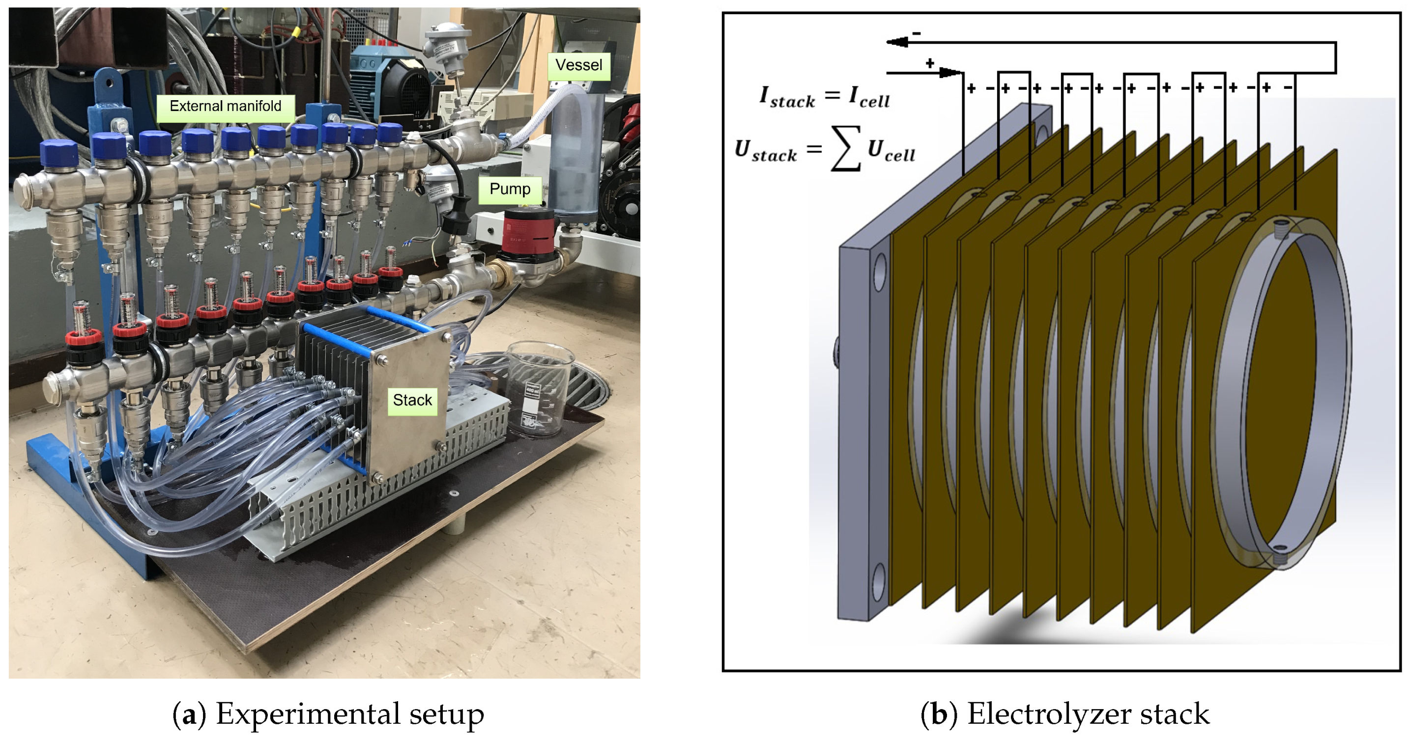
3.1. Experimental Setup

Figure 3a illustrates the experimental setup used for the electrolysis tests, consisting of an external manifold with simple hosing to enable parallel electrolyte flow, a pump to provide constant circulation of the medium through the system, a vessel for the medium input and output, and an electrolyzer stack. The electrolyzer stack is schematically presented in Figure 3b. The stack consists of series-connected bipolar electrodes (uncoated 316 L stainless steel with a thickness of 1 m m ) separated by tubular plastic (PVC) spacers and end plates made of stainless steel acting both as a current collector and a pressure plate. The effective electrode area of each circular electrode is 86.6 cm 2 , with a diameter of 10.5 c m . The distance between the electrodes is 10 m m , and there are ten cells connected in series. The current is supplied using a standard cable shoe to the connector bolt welded to the end plate. The stack structure is compressed with insulated tightening rods assembled through the corner holes of the pressure plates. The hosing providing the parallel electrolyte flow of the cells is made from plastic (PVC) tube with a diameter of 6 m m . The measurement system control and data logging were implemented in a LabVIEW environment. Current was supplied and measured with a Sorensen DLM (40 V /15 A ) laboratory power source with a current stability of 7.5 m A . The stack and cell voltages were measured with a Keithley 2701 data acquisition system with a voltage measurement accuracy of 0.015 % for reading and 0.006 % for the 100 V range. A Grundfos Alpha2 25–60 household hot water circulation pump with an integrated frequency converter was used to pump the electrolyte. Tests were performed at room temperature. The temperatures of the manifold inlet and outlet flows were measured with PT100 thermistors with an IPAQ-C201 mA-signal transmitter. The mA signal was further read with a NI-9208 C series current input module.

3.2. Electrolyte

The mineral medium used for the cultivation of HOB is based on Leibniz-Institut DSMZ growth medium number 81 [23] with the following changes: (i) The major chloride compounds were replaced with the corresponding sulfates to minimize the production of chlorine gas by the electrolysis current. The trace element solution SL-6 of Pfennig [24] used in the medium preparation was left unchanged both for the sake of convenience and because some bacteria might require chloride as a micronutrient, especially at high salt concentrations [25]. (ii) The ferric ammonium citrate concentration was reduced to 5 m g / L from the 50 m g / L recommended by DSMZ to prevent iron precipitation from the medium during storage of even a few days. (iii) Na2SO4 was added to increase the electrical conductivity of the medium and reduce the required electrolysis voltage. The final mineral medium composition was 2.3 g / L KH2PO4, 2.9 g / L Na2HPO4 · 2H2O, 5.45 g / L Na2SO4, 1.19 g / L (NH4)2SO4, 0.5 g / L MgSO4· 7H2O, 11.7 m g / L CaSO4 · 2H2O, 4.4 m g / L MnSO4· H2O, 5 m g / L NaVO3 (metavanadate), 0.5 g / L NaHCO3, 5 m g / L ferric ammonium citrate (16% Fe), 0.5 m g / L ZnSO4 · 7H2O, 1.5 m g / L H3BO3, 1 m g / L CoCl2· 6H2O, 0.05 m g / L CuCl2· 2H2O, 0.1 m g / L NiCl2· 6H2O, 0.15 m g / L Na2MoO4 · 2H2O. The medium had a pH of 7 and a conductivity of 12 m S / c m .

4. Results and Discussion

Figure 4a depicts the measured currents as a function of time with various voltages ranging from 30 V to 39 V during 1 h of experimental time. The stack voltage as a function of stack current is presented in Figure 4b, and the cell voltage as a function of current density is shown in Figure 4c.
The main parameters of the electrolyzer stack efficiency were calculated based on the collected current–voltage relationships. Figure 5a presents the hydrogen production rate and the electrical supply power as a function of the stack current density. Figure 5b,c shows the specific energy consumption and the electrolyzer efficiency as a function of the stack current density. The values of the aforementioned parameters are summarized in Table 1.

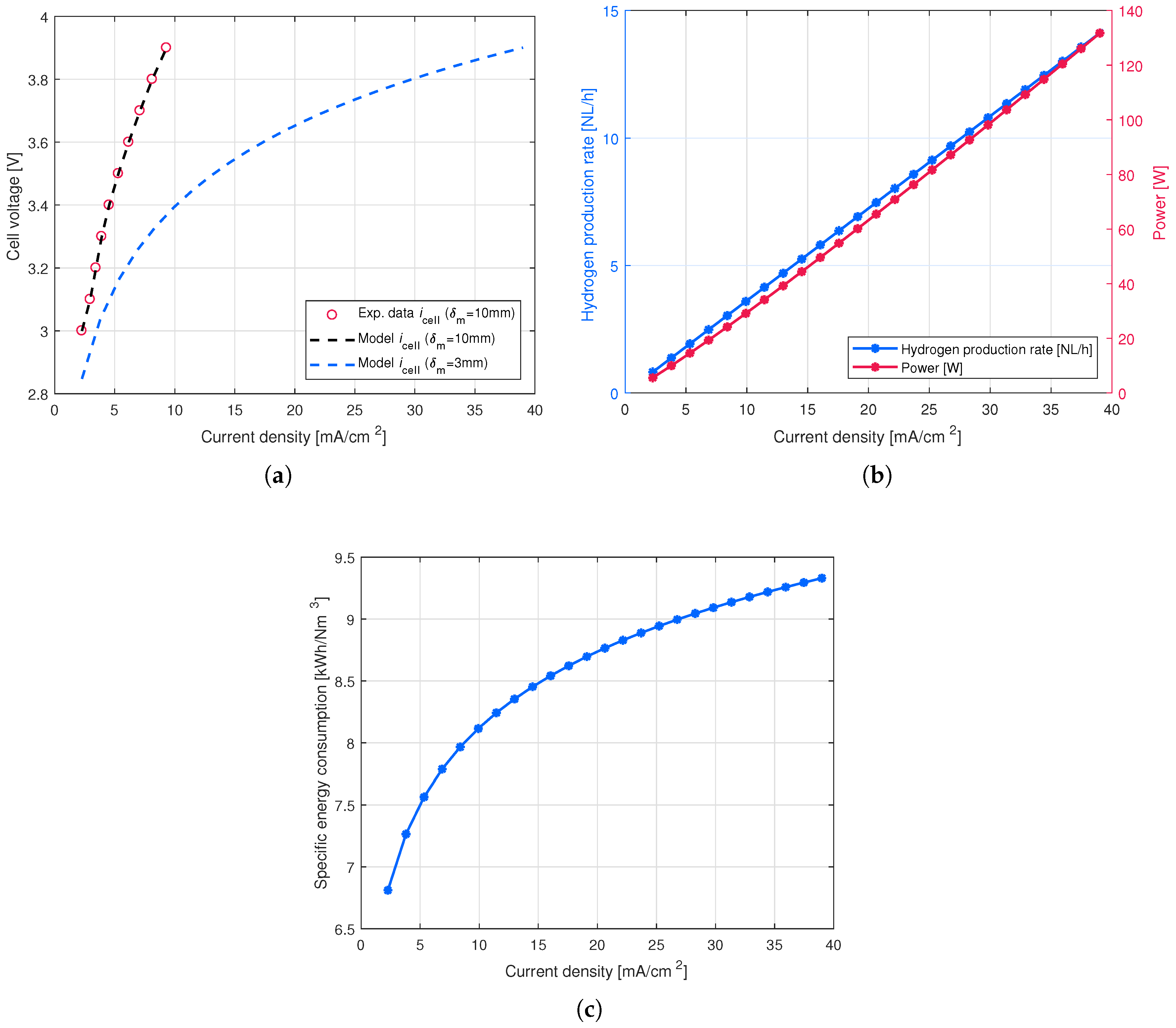
4.1. Effect of Electrode Distance on the Cell Performance

As was stated in Section 2, the efficiency of the HOB cultivation process can be enhanced by reducing the electric power consumption during the water electrolysis process. According to Equation (1), the overall cell potential is the sum of different overpotentials, one of which is the ohmic overpotential, representing the electrical resistance of the cell elements. We may state that the ohmic overpotential is mainly caused by the voltage loss across the cultivation medium with a low conductivity. Consequently, a reduction in space between the electrodes in the stack substantially decreases the electrical resistance and leads to elevated current densities at the same cell potentials. Having measured the current and voltage data of the electrobioreactor electrolyzer stack with a 10 m m distance between the electrodes, the corresponding data were calculated for the same stack with a 3 m m distance between the electrodes, according to the simplified cell voltage model published in [26] and presented by the following equation:
U cell = U rev + δ m i cell σ m + α arcsinh i cell 2 i 0 ,
where δ m is the distance between the electrodes in ( c m ), σ m is the conductivity of the medium in ( S / c m ), α is the charge transfer coefficient for the anode and the cathode separately, and i o is the exchange current density on the electrode surfaces.
The modeling results of the stack current densities as a function of cell voltage with a 10 m m and 3 mm distance between the electrodes are illustrated in Figure 6a. Figure 6b shows the hydrogen production rate and the power as a function of stack current density. Figure 6c depicts the specific energy consumption as a function of the stack current density for the electrolyzer stack with a 3 m m distance between the electrodes.

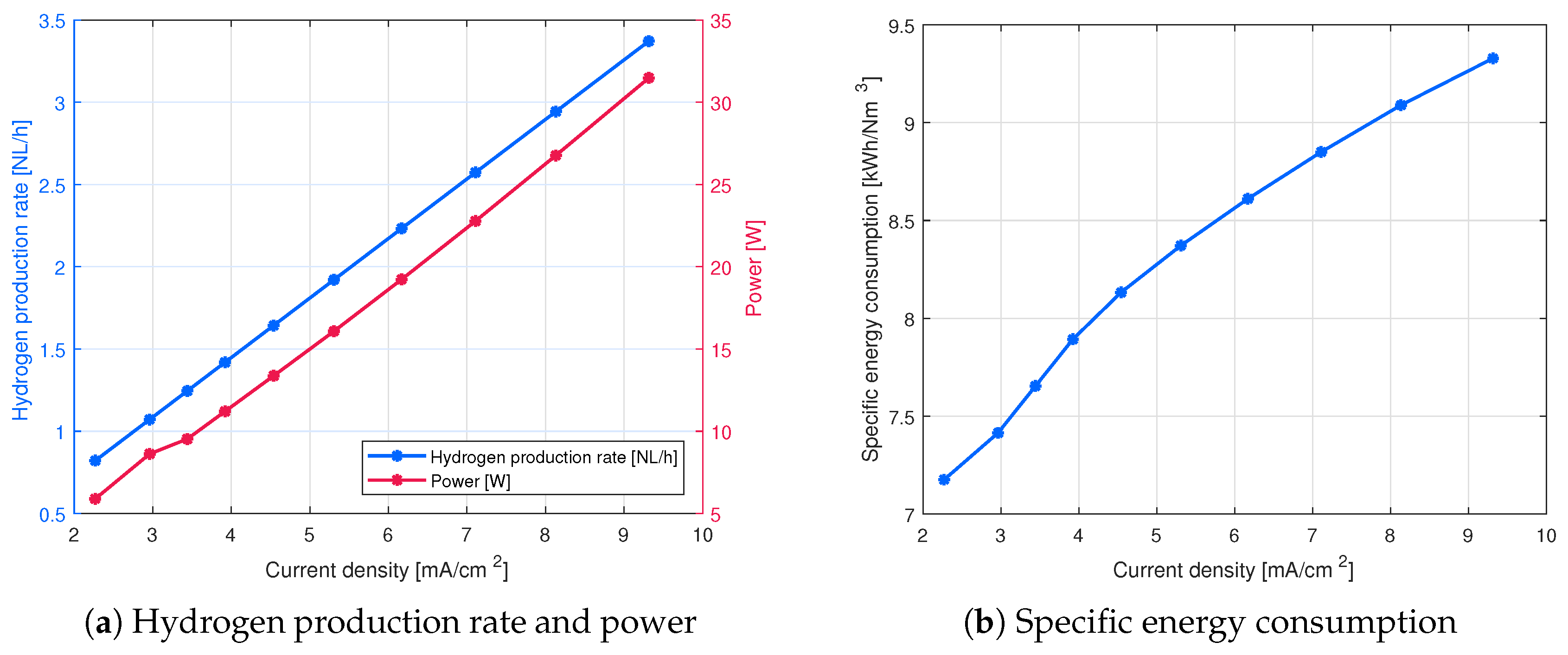
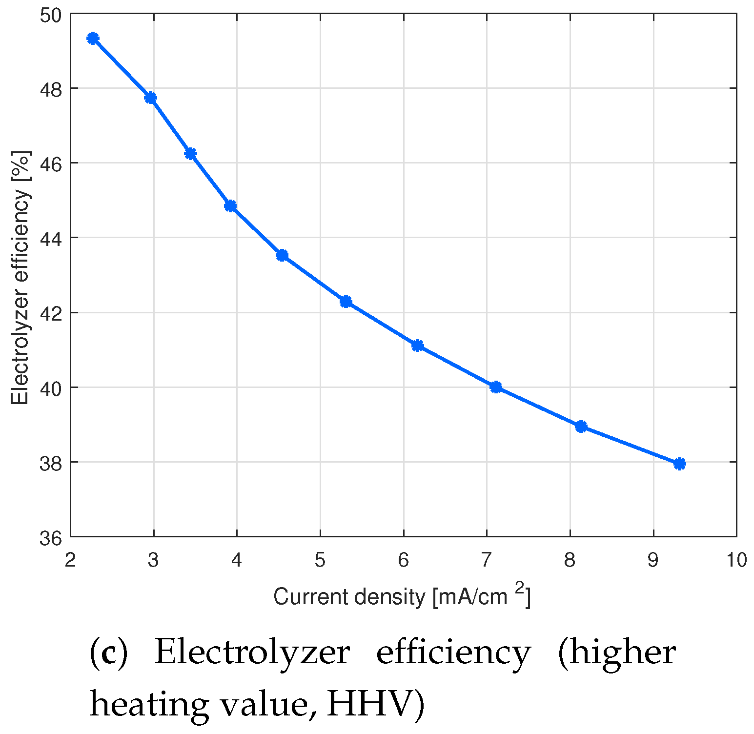
4.2. Volumetric Productivity

As an example, a bioreactor with a volume of 1000 L with a specific production rate of 0.2 g /( L h ) would produce 200 g of biomass per hour. With the 2.5 g /mol biomass yield from hydrogen, the hydrogen consumption is 80 mol/ h . If CoP-coated electrodes are used, a 50% HHV efficiency can be reached with current densities up to 5 m A / c m 2 [26]. According to (2), the required cell area is 85.8 m 2 . By assuming that there are 100 circular cells in series and that the total axial length of the cell is 5 m m , the electrolyzer volume is 429 L . Thus, it can be stated that with coated electrodes, the electrolyzer volume is roughly half of the bioreactor volume, and in the case of noncoated stainless steel electrodes, the bioreactor and electrolyzer volumes are roughly the same. This leads to the fact that the actual bioreactor tank might not be needed at all, or, at least, the size could be significantly reduced, as the electrolyzer stack structure provides a significant proportion of the volume required for microbial growth.

5. Conclusions

Hydrogen production for HOB cultivation in an electrobioreactor with in situ water electrolysis was studied. A stack structure was introduced to enhance hydrogen production compared with reactor tank-immersed electrodes. The energy efficiency of the prototype stack was experimentally studied. It was found that with a water electrolysis energy efficiency (HHV) of 50%, the current density could be up to a range of 5 m A / c m 2 with coated electrodes. Thus, the volume of the in situ water electolyzer stack is approximately half of the total volume required for microbial cultivation. However, the results are based on the energy efficiency of the water electrolysis process, and the maximum allowed current density that does not harm microbial growth has not been studied yet.

Author Contributions

Conceptualization, G.G., V.R., L.S.O., P.K. and J.A.; methodology, G.G., V.R., L.S.O., and P.K.; software, G.G. and V.R.; formal analysis, G.G. and V.R.; investigation, G.G., L.S.O. and V.R.; Writing—Original Draft preparation, G.G. and V.R.; Writing—Review and Editing, L.S.O., P.K. and J.A.; project administration, V.R. and J.A.

Funding

Financial support was given by the Technology Industries of Finland Centennial Foundation and Jane and Aatos Erkko Foundation for the project “Feed and food from carbon dioxide and electricity—research and piloting of the future protein production”.

Conflicts of Interest

The authors declare no conflict of interest. The funders had no role in the design of the study; in the collection, analyses, or interpretation of data; in the writing of the manuscript, or in the decision to publish the results.

Appendix A. Materials and Methods

Appendix A.1. BES Cultivation

The HOB strain used in the BES cultivation was C u p r i a v i d u s n e c a t o r H16 (DSM 428) supplied by the Leibniz-Institut DSMZ—Deutsche Sammlung von Mikroorganismen und Zellkulturen GmbH. The inoculum for the BES cultivation was grown in 20 m L liquid volume shake flasks under 12.5 % H2, 13.1 % O2, 25% CO2, and 49.4 % N2 for nine days. The BES cultivation was performed in a small-scale (60 m L liquid volume) bioreactor with immersed rod electrodes (cathode: stainless steel, anode: iridium-oxide-coated titanium). The reactor was supplied with gaseous CO2 and a constant electrolysis current of 18 m A . The bioreactor was jacketed, and the cultivation temperature was kept constant at 30 °C with external water circulation. Prior to the inoculation, reactors filled with a sterile growth medium were allowed to stabilize to the temperature, electrolysis, and CO2 purge conditions for 2 h . The first data point was recorded at the end of the stabilizing period before inoculation. The BES reactor was inoculated with an appropriate volume of inoculum (2 m L ) to get an initial optical density of 0.2 units for the cultivation broth. Subsequently, the optical density (OD) at 600 nm was measured daily by withdrawing samples of 1 m L from the reactor. The OD was correlated with the cell density by measuring the dry cell density at the end of the cultivation period from an aliquot of 2 m L . The biomass in the aliquot was separated by centrifugation, washed twice with pure water (Milli-Q Advantage A10 Water Purification system by Millipore), and finally, the biomass was dried at 105 °C. The correlation between the OD and the dry cell density was found to be 1 OD unit = 0.255 g / L biomass. During the BES cultivation, the hydrogen concentration at the reactor gas exhaust was measured with a Pfeiffer Vacuum Omnistar GDS 301 gas analysis system. Before cultivation, the Omnistar was calibrated against the known H2 concentration of 10% in a reference gas supplied by AGA.

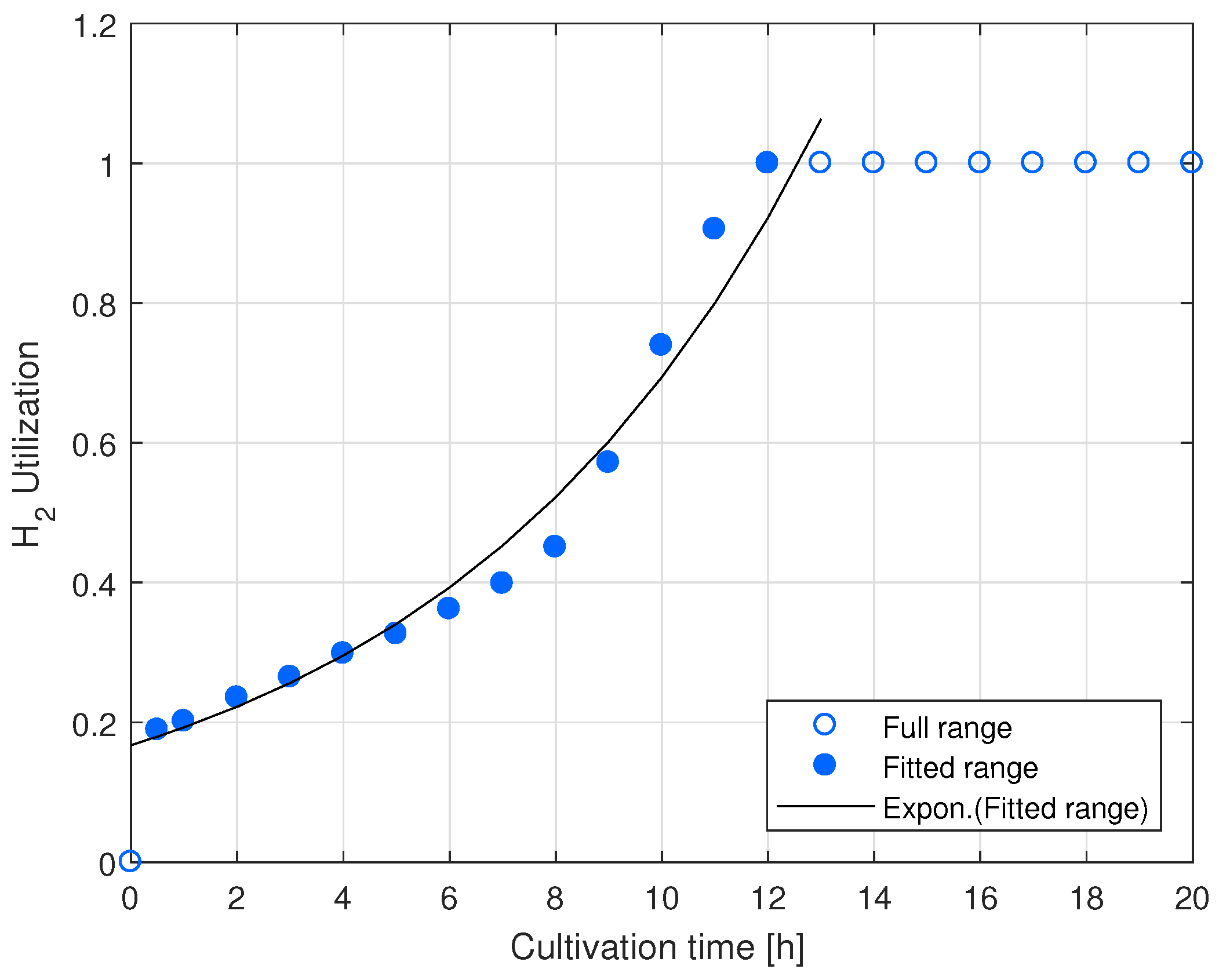
Appendix A.2. HOB Growth Rate Calculation from the Outlet Hydrogen Concentration Data

For the HOB biomass growth rate determination, the hydrogen concentration at the bioreactor outlet was transformed into a hydrogen utilization ratio:
H 2 Utilization = c H 2 Out , Initial c H 2 Out c H 2 Out , Initial ,
where c H 2 Out is the hydrogen concentration at the reactor outlet, and c H 2 Out , Initial is the concentration at the beginning of cultivation. The use of H2 was assumed to increase at the same rate as the biomass growth. A generic exponential function was fitted to the increasing range (between 0.5 h –12 h ) of the H2 utilization data:
H 2 Utilization = A e μ t ,
where A is a pre-exponential constant, and μ is the rate constant. The best fit was achieved with A = 0.1675 and μ = 0.1422 h 1 . Because the biomass growth is dependent on the hydrogen consumption, the rate constant can be considered an approximation of the biomass growth rate. The H2 utilization data and the fitted curve are shown in Figure A1.
Figure A1. Development of hydrogen utilization in the small-scale BES. The exponential curve fitted to the part of the data range is associated with exponential biomass growth.
Energies 12 01904 g0a1

References

  1. Brown, T.W.; Bischof-niemz, T.; Blok, K.; Breyer, C.; Lund, H.; Mathiesen, B.V. Response to ‘Burden of proof: A comprehensive review of the feasibility of 100% renewable-electricity systems. Renew. Sustain. Energy Rev. 2018, 92, 834–847. [Google Scholar] [CrossRef]
  2. Kousksou, T.; Bruel, P.; Jamil, A.; El Rhafiki, T.; Zeraouli, Y. Energy storage: Applications and challenges. Sol. Energy Mater. Sol. Cells 2014, 120, 59–80. [Google Scholar] [CrossRef]
  3. Vidal, F.; Koponen, J.; Ruuskanen, V.; Bajamundi, C.; Kosonen, A.; Simell, P.; Ahola, J.; Frilund, C.; Elfving, J.; Reinikainen, M.; et al. Power-to-X technology using renewable electricity and carbon dioxide from ambient air: SOLETAIR proof-of-concept and improved process concept. J. CO2 Util. 2018, 28, 235–246. [Google Scholar]
  4. Pikaar, I.; Matassa, S.; Rabaey, K.; Bodirsky, B.L.; Popp, A.; Herrero, M.; Verstraete, W. Microbes and the Next Nitrogen Revolution. Environ. Sci. Technol. 2017, 51, 7297–7303. [Google Scholar] [CrossRef]
  5. Kracke, F.; Wong, A.B.; Maegaard, K.; Deutzmann, J.S.; Hubert, M.A.; Hahn, C.; Jaramillo, T.F.; Spormann, A.M. Robust and biocompatible catalysts for efficient hydrogen-driven microbial electrosynthesis. Commun. Chem. 2019, 2, 45. [Google Scholar] [CrossRef]
  6. Matassa, S.; Boon, N.; Verstraete, W. Resource recovery from used water: The manufacturing abilities of hydrogen-oxidizing bacteria. Water Res. 2015, 68, 467–478. [Google Scholar] [CrossRef] [PubMed]
  7. Linder, T. Making the case for edible microorganisms as an integral part of a more sustainable and resilient food production system. Food Secur. 2019. [Google Scholar] [CrossRef]
  8. Pikaar, I.; Vrieze, J.D.; Rabaey, K.; Herrero, M.; Smith, P.; Verstraete, W. Science of the Total Environment Carbon emission avoidance and capture by producing in-reactor microbial biomass based food, feed and slow release fertilizer: Potentials and limitations. Sci. Total. Environ. 2018, 644, 1525–1530. [Google Scholar] [CrossRef] [PubMed]
  9. Volova, T.G.; Barashkov, V.A. Characteristics of proteins synthesized by hydrogen-oxidizing microorganisms. Appl. Biochem. Microbiol. 2010, 46, 574–579. [Google Scholar] [CrossRef]
  10. Oesterholt, F.; Matassa, S.; Palmen, L.; Roest, K.; Verstraete, W. Pilot scale production of single cell proteins using the power-to-protein concept Future global challenges. In Proceedings of the 2nd International Resource Recovery Conference, New York, NY, USA, 5–9 August 2018; pp. 1–16. [Google Scholar]
  11. Matassa, S.; Verstraete, W.; Pikaar, I.; Boon, N. Autotrophic nitrogen assimilation and carbon capture for microbial protein production by a novel enrichment of hydrogen-oxidizing bacteria. Water Res. 2016, 101, 137–146. [Google Scholar] [CrossRef]
  12. Yu, J. Bio-based products from solar energy and carbon dioxide. Trends Biotechnol. 2014, 32, 5–10. [Google Scholar] [CrossRef] [PubMed]
  13. Torella, J.P.; Gagliardi, C.J.; Chen, J.S.; Bediako, D.K.; Colón, B.; Way, J.C.; Silver, P.A.; Nocera, D.G. Efficient solar-to-fuels production from a hybrid microbial–water-splitting catalyst system. Proc. Natl. Acad. Sci. USA 2015, 112, 2337–2342. [Google Scholar] [CrossRef] [PubMed] [Green Version]
  14. Liu, C.; Ziesack, M.; Silver, P.A. Water splitting–biosynthetic system with CO2 reduction efficiencies exceeding photosynthesis. Science 2016, 352, 1210–1213. [Google Scholar] [CrossRef] [PubMed]
  15. Liu, C.; Sakimoto, K.K.; Colón, B.C.; Silver, P.A.; Nocera, D.G. Ambient nitrogen reduction cycle using a hybrid inorganic–biological system. Proc. Natl. Acad. Sci. USA 2017, 114, 6450–6455. [Google Scholar] [CrossRef] [Green Version]
  16. Liu, C.; Colón, B.E.; Silver, P.A.; Nocera, D.G. Solar-powered CO2 reduction by a hybrid biological∣inorganic system. J. Photochem. Photobiol. A Chem. 2018, 358, 411–415. [Google Scholar] [CrossRef]
  17. Nangle, S.N.; Sakimoto, K.K.; Silver, P.A.; Nocera, D.G. Biological-inorganic hybrid systems as a generalized platform for chemical production. Curr. Opin. Chem. Biol. 2017, 41, 107–113. [Google Scholar] [CrossRef]
  18. Krieg, T.; Sydow, A.; Schro, U.; Schrader, J.; Holtmann, D. Reactor concepts for bioelectrochemical syntheses and energy conversion. Trends Biotechnol. 2014, 32, 645–655. [Google Scholar] [CrossRef] [PubMed]
  19. Decourt, B.; Lajoie, B.; Debarre, R.; Soupa, O. The Hydrogen-Based Energy Conversion FactBook; The SBC Energy Institute: Melbourne, Australia, 2014. [Google Scholar]
  20. Ursúa, A.; Gandía, L.; Sanchis, P. Hydrogen Production From Water Electrolysis: Current Status and Future Trends. Proc. IEEE 2012, 100, 410–426. [Google Scholar] [CrossRef]
  21. Yu, J.; Munasinghe, P. Gas Fermentation Enhancement for Chemolithotrophic Growth of Cupriavidus necator on Carbon Dioxide. Fermentation 2018, 4, 63. [Google Scholar] [CrossRef]
  22. Reilly, C.O.; Farrell, M.; Harvey, D.; Cassidy, J. Operation of an inexpensive bipolar alkaline electrolyser producing a mix of H2/O2 fuel. Int. J. Hydrogen Energy 2015, 41, 2197–2201. [Google Scholar] [CrossRef]
  23. DSMZ GmbH. 81. Mineral Medium For Chemolithotrophic Growth (H-3); DSMZ: Braunschweig, Germany, 2011. [Google Scholar]
  24. Pfennig, N. Rhodopseudomonas globiformis, sp. n., a new species of the Rhodospirillaceae. Arch. Microbiol. 1974, 100, 197–206. [Google Scholar] [CrossRef]
  25. Roeßler, M.; Sewald, X.; Müller, V. Chloride dependence of growth in bacteria. FEMS Microbiol. Lett. 2006, 225, 161–165. [Google Scholar]
  26. Givirovskiy, G.; Ruuskanen, V.; Ojala, L.; Lienemann, M.; Kokkonen, P.; Ahola, J. Electrode material studies and cell voltage characteristics of the in situ water electrolysis performed in a pH-neutral electrolyte in bioelectrochemical systems. Heliyon 2019, 5, e01690. [Google Scholar] [CrossRef]
Figure 1. BES cultivation of C u p r i a v i d u s n e c a t o r H16 with immersed electrodes, compared with the hydrogen concentration at the bioreactor gas outlet.
Energies 12 01904 g001
Figure 2. Proposed process diagram of the electrobioreactor with an external electrolyzer stack for the hybrid biological-inorganic (HBI) process.
Energies 12 01904 g002
Figure 3. Experimental setup used for the electrolysis tests and a schematic of the electrolyzer stack. The ten cells are electrically connected in series, and the electrolyte flow is equally divided between the parallel cells by the manifolds.
Energies 12 01904 g003
Figure 4. Measured currents and current densities of the electrolyzer stack with various supply voltages. (a) Measured currents as a function of time with various voltages; (b) stack voltage as a function of stack current; (c) cell voltage as a function of current density.
Energies 12 01904 g004
Figure 5. Main energy efficiency parameters of the electrolyzer stack.
Energies 12 01904 g005aEnergies 12 01904 g005b
Figure 6. The main energy efficiency parameters of the electrolyzer stack with a decreased distance between the electrodes. (a) Cell voltage as a function of current density at variable electrode separations; (b) hydrogen production rate and supply power as a function of current density with a 3 mm distance between the electrodes; (c) specific energy consumption as a function of the current density with a 3 mm distance between the electrodes.
Energies 12 01904 g006
Table 1. Main energy efficiency parameters of the electrolyzer stack calculated based on the measured stack voltage and current.
U stack
[V]
I stack
[A]
f H 2
[NL/h]
E s
[kWh/(Nm 3 )]
η E , HHV
[%]
300.200.827.1849.33
310.261.077.4247.74
320.301.257.6546.25
330.341.427.8944.85
340.391.648.1343.53
350.461.928.3742.29
360.532.238.6141.11
370.622.578.8540.00
380.702.949.0938.95
390.813.379.3337.95

