1. Introduction
The power of an electrical machine is proportional to both its rotor excitation field and rotational speed. Thus in order to achieve high-power density machines, both magnetic field and rotational speeds must be as large as possible. Speeds above 15,000 rpm are not possible with active coils attached to the rotor due to excessive centrifugal stresses, challenges of handling power, and cooling system interfaces. Additionally, copper windings cannot feasibly produce magnetic fields above ~1.5 T, so higher fields require superconducting coils [
1]. A recent review [
2] shows demonstrations of superconducting machines up to 10,000 RPM, with high-temperature superconductor (HTS) rotors demonstrated to 15,000 RPM.
Machines employing permanent magnets (PM) on the rotor have been built for high speed applications. However, in such machines, PM are held on the rotor with a structural support. The permissible rotor speed is limited by the constraints of the structural support. For example, [
3] describes a PM machine rated 45 kW at 32,000 RPM but its diameter is limited to 92 mm. However, the AC homopolar machine described in this paper is rated 500 kW at 25,000 RPM and a rotor diameter of 200 mm. Our rotor made of a single material—the rotor speed is only limited by centrifugal stresses in the rotor material. It is possible to achieve much larger machine with a rotor made of a single solid material.
The recent emergence of commercially produced HTS wire has radically changed both the cost-metric and technical viability of superconducting machines [
4]. HTS wires are superconducting at temperatures up to 93 K, enabling mechanical refrigerators to be used in conjunction with gas-exchange cooling. This eliminates many of the problems associated with rotating liquid cryogens, whilst the elevated operating temperature provides ‘thermal head-room’, further enhancing system stability. As a result, novel HTS generators and motors are currently a subject of hot global interest [
5,
6].
The key objectives are achieving compact and lightweight devices of the highest possible torque/weight and electrical efficiencies [
7]. One typical application powers electric aircraft propulsion fans with energy generated from on-board generators directly coupled to high-speed gas turbines [
8]. A second application is machines which act as both motor and generator integrated with high-speed flywheels for energy storage [
9]. This system could be employed in transit systems as a method of fast energy recovery and delivery. Either on moving assets such as buses, or at stationary transport nodes such as subway stations [
10,
11]. Alternately, the flywheel energy storage device could act as a battery for storing surplus solar and wind energy for later use during lean periods of energy generation [
12,
13].
HTS exciter coils enable realizing compact and light-weight machines. An alternating current (AC) homopolar synchronous machine topology [
14,
15] enables high rotational speeds achieved by removing the requirement for active rotating coils, making it ideal for high power applications. Building such a machine using conventional copper excitation coils presents significant cooling challenges and limits the size of such a machine to a power rating of only a few kilowatts. However, megawatt rated machines become possible by replacing the direct current (DC) field excitation coil with a suitable superconducting coil.
This paper describes design and analysis for machines employing a HTS DC excitation coil. Different approaches are discussed for building AC armature coils using conventional copper coil technologies. Challenges of building and cooling both armature and field coils are discussed, and possible approaches are suggested for handing them. The application example used is a stationary fast energy storage system for use in subway systems, however, much of what is discussed here is applicable for airborne applications such as those studied by Sivasubramaniam [
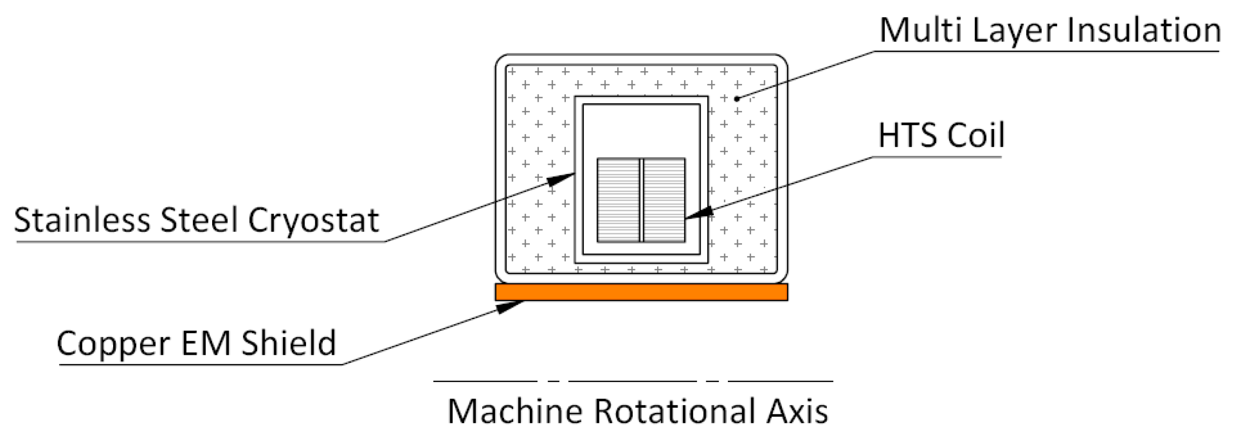
16]. The machine described in this reference was designed for aerospace application with intention of keeping size and mass as small as possible, whereas the current machine is being designed for on ground application to mate with a flywheel for energy storage. An electromagnetic shield (Figure 3) has been incorporated for reducing AC losses in the superconducting coil and minimizing refrigerator cooling power.
3. Machine Configuration
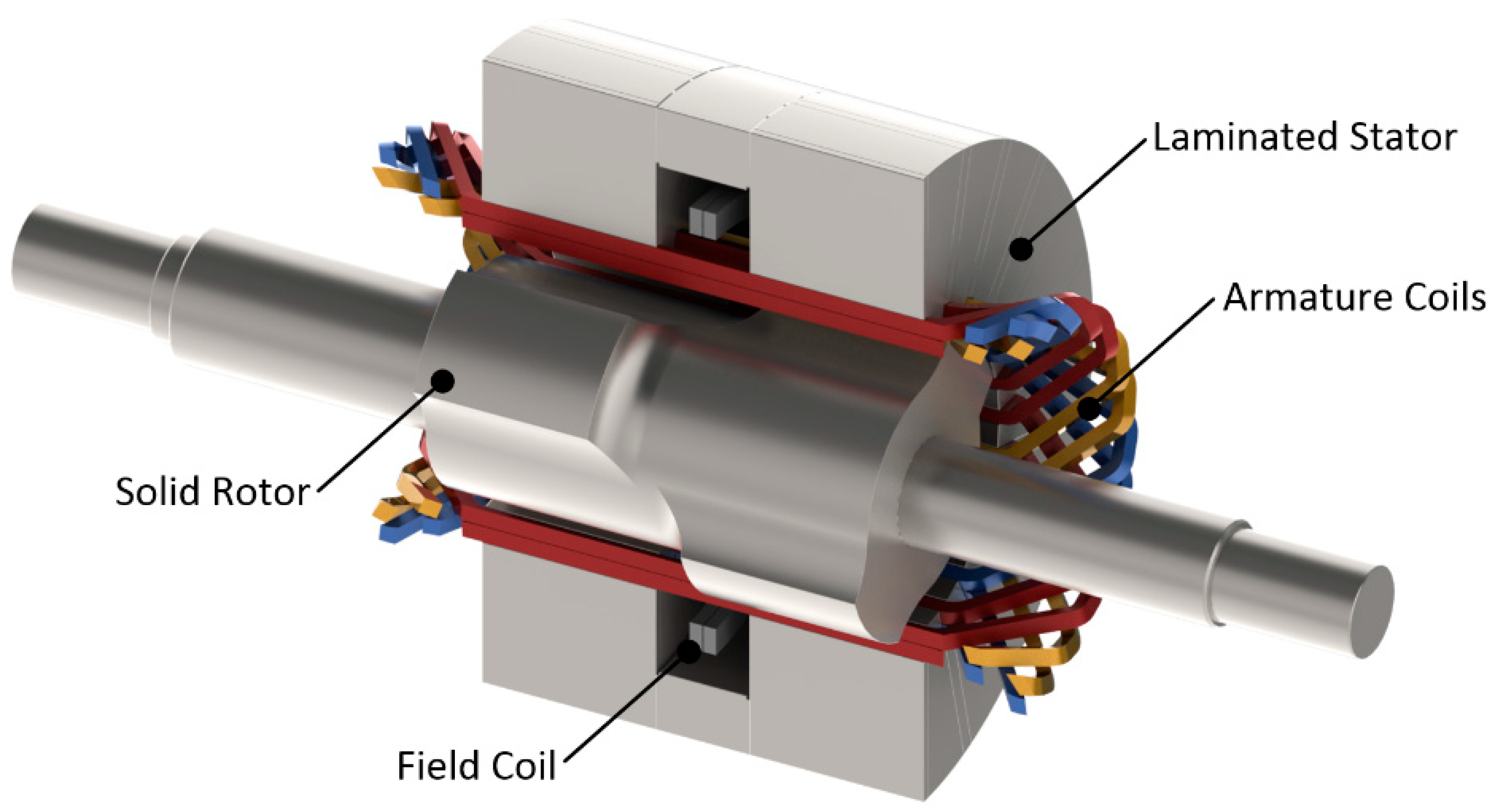
A cutaway diagram of the AC homopolar motor/generator is shown in
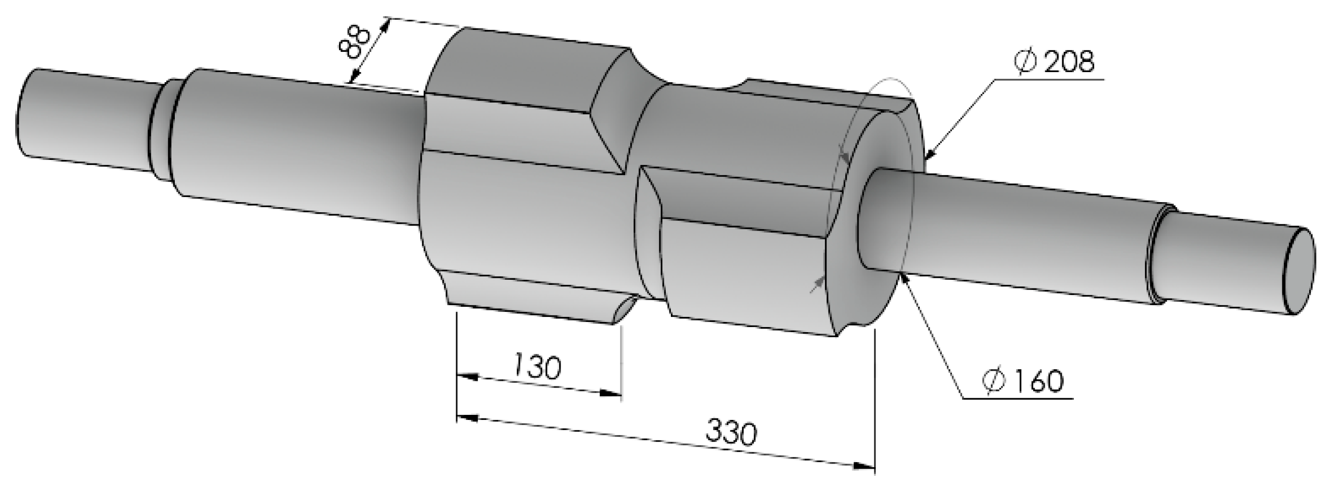
Figure 1. The shaft and rotor have not been sectioned so as to show the four-pole layout, with 90° rotationally offset poles. The three armature coil colors illustrate the three phases winding scheme. The HTS coil cryostat and its surrounding insulation have been omitted for clarity, as has an electromagnetic (EM) shield located between the armatures and the superconducting coils. The ferromagnetic poles are shaped as in any salient pole machine so as to reduce harmonic and torque ripple to acceptable levels, as described in the next section.
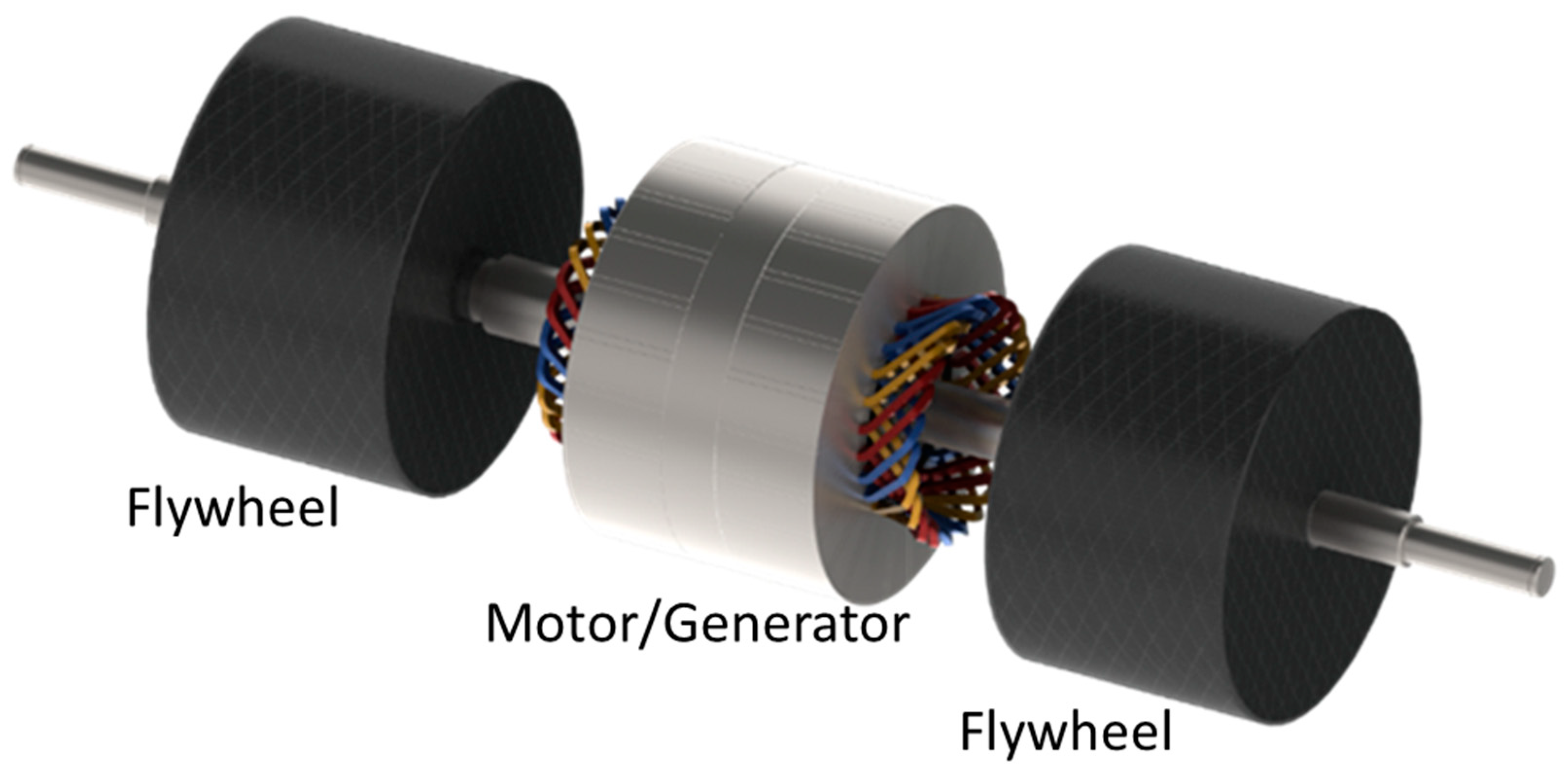
In the flywheel energy storage system, the homopolar motor/generator is located between two glass fiber reinforced polymer flywheels as shown in
Figure 2. This arrangement reduces the required shaft size by halving the power transferred through any one part of the shaft. This assembly is housed in a vacuum chamber, with the rotating components supported only by magnetic levitating bearings, enabling operation up to 25,000 RPM. At the high rotational speed desired, housing the system in a vacuum is required to reduce windage friction that would otherwise result in high drag. Frictionless non-contact magnetic bearings are also required as mechanical bearings would not be able to operate continuously due to frictional losses and wear [
18].
The design of the flywheels, vacuum chamber, and bearings are outside the scope of this paper. Discussion of the armature, rotor, and stator follows below.
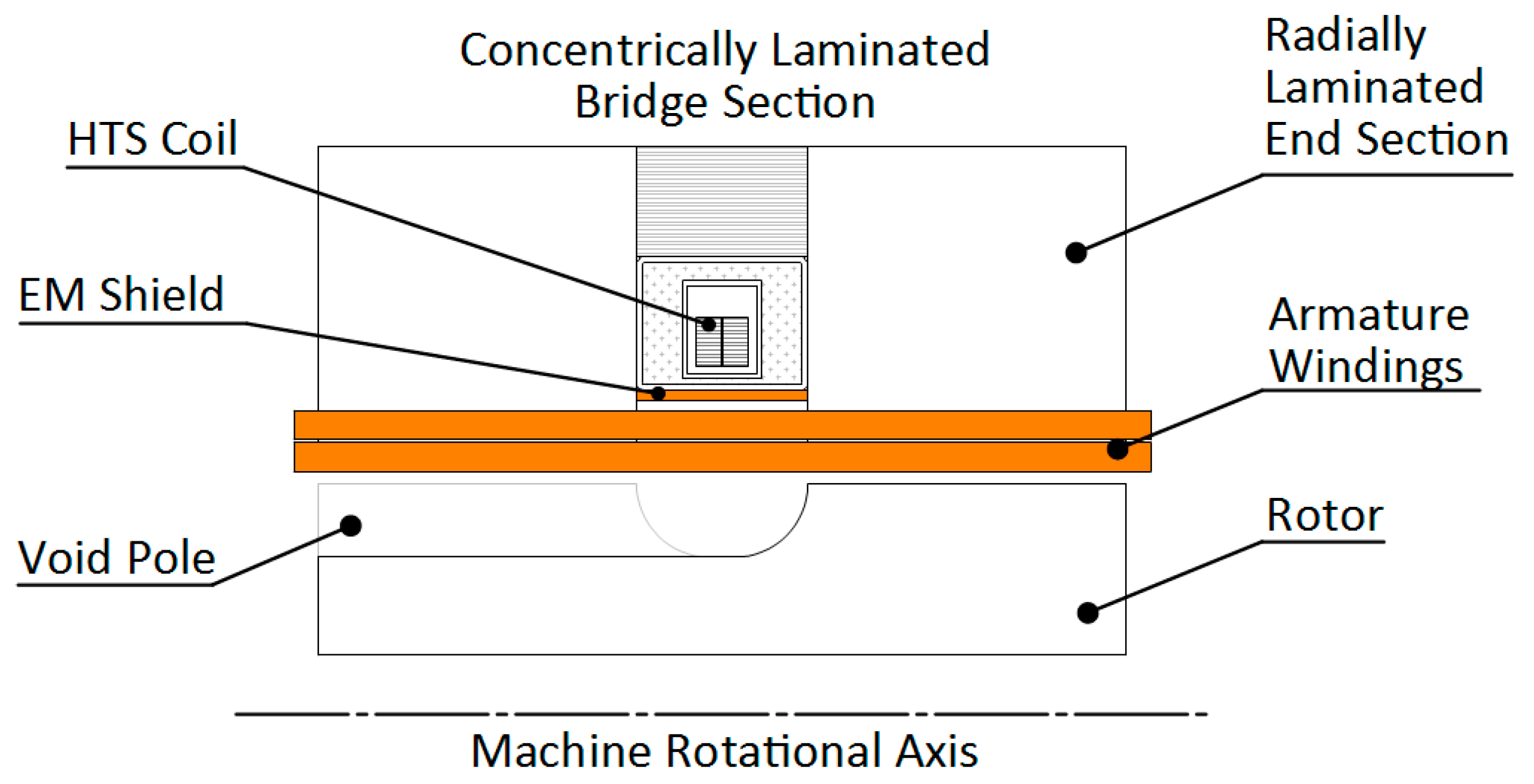
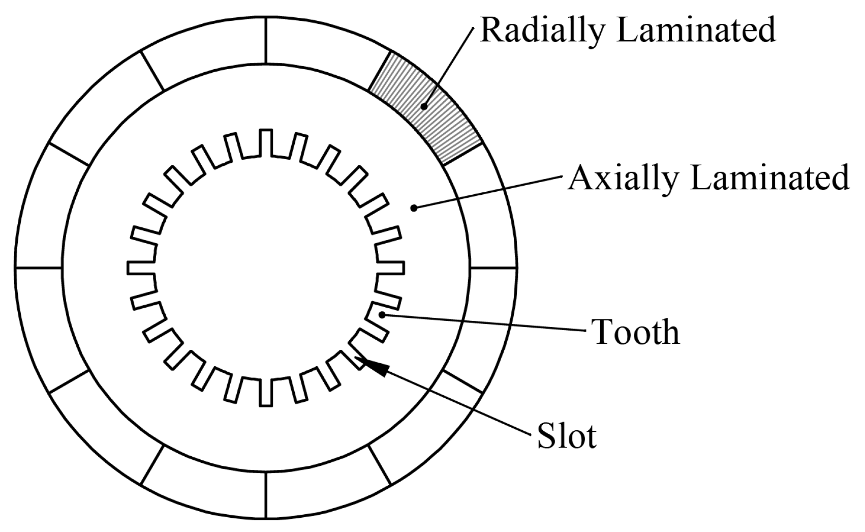
Figure 3 shows the cross-section of the machine with main components. The stator core is axially split into two equal parts and the superconducting excitation coil is sandwiched between them. The stator core is constructed using laminated magnetic steel.
Section 3 and
Section 8 detail the lamination directions and the unconventional magnetic flux path these must support. Armature coil sides are shown laid axially on the stator. High rotational frequency combined necessitates the rotor be machined from a single piece, and the rotor’s role in augmenting the magnetic field supplied by the exciter coil requires this piece to be magnetic steel. In
Figure 3 the rotor is shown with one solid-pole (on the right) and one void-pole (on the left) aligned with stator core—the void pole is located at the mid-point between two adjacent solid-poles on the rotor and represents the part of the rotor volume where minimum magnetic flux is supported, i.e., where there is no magnetic steel.
4. Sizing Analysis
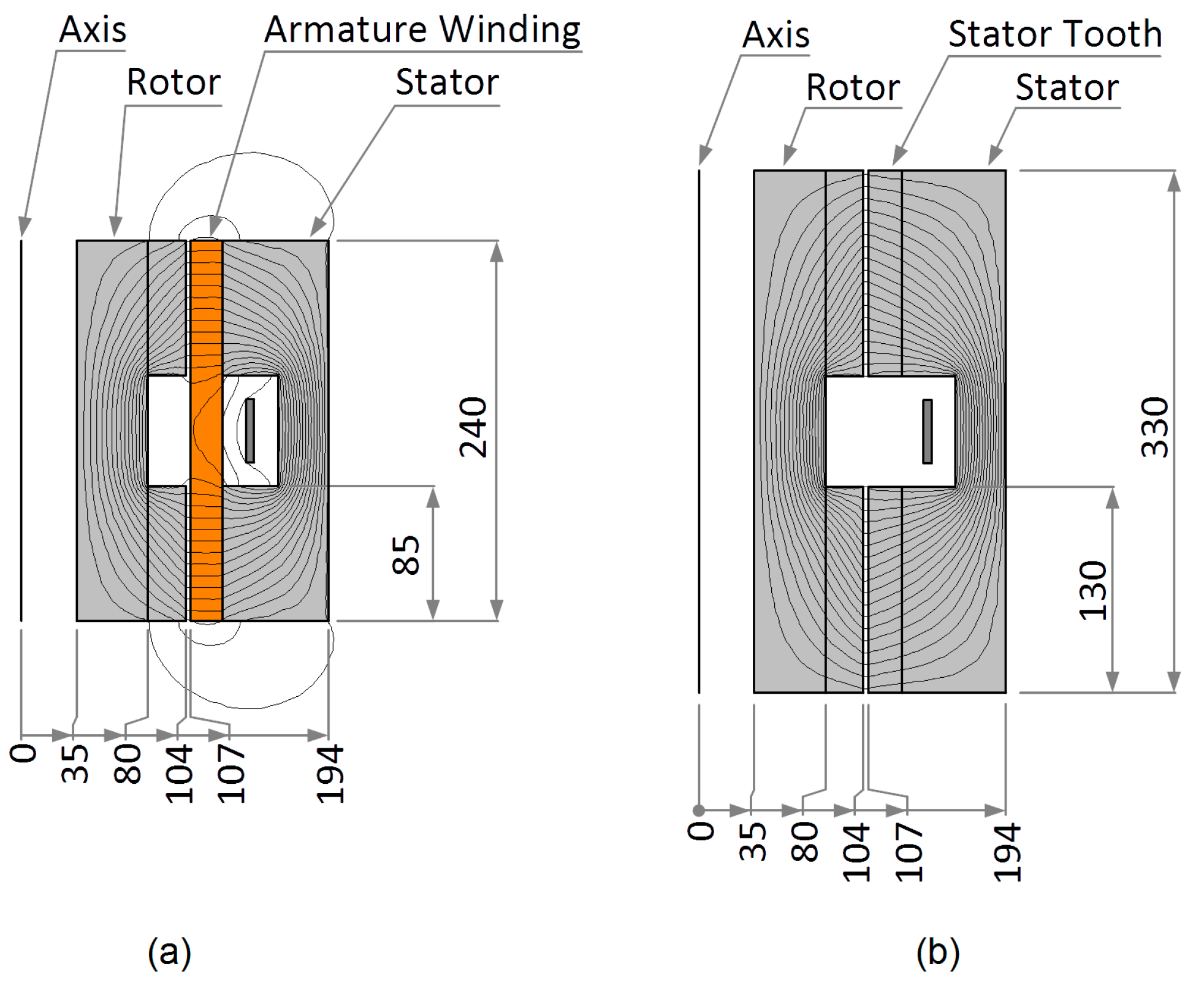
A 2D approximation of the machine as shown in
Figure 4, is utilized for sizing analysis with 2D FEA. In this approximation the rotor poles are not offset by 90 degrees as the behavior of interest is the capability of the machine to effectively route flux within the rotor and stator. Two kinds of armature windings were considered; (a) coils in air-gap, and (b) coils in slots in the iron core.
Figure 4a shows a cross-section with armature coils residing in the gap between the stator and rotor, i.e., there are no stator iron teeth. Although a variety of armature winding configurations are possible, a unique single-layer (SL) winding design is considered for this study. The dimensions of this cross-section have been selected to suit the specifications of
Table 1.
Likewise,
Figure 4b shows the cross-section with armature coils housed between iron stator teeth. A double-layer (DL) winding configuration is selected here. The radial depth of the armature coils is same as for the air-gap winding coils (
Figure 4a).
In each of these simulations the stator and rotor are taken to be unlaminated 1020 steel with non-linear BH curve saturating at approximately 2.8 T. Each representative cross-section considers the shaft material to be air and the rotor has been sized so as not to require the shaft to be part of the magnetic circuit. Although the design of a functional generator which supplies alternating current at the stator windings requires a non-symmetric lobed rotor, the 2D approximations used for sizing are axisymmetric as the total magnetic flux is not affected by the asymmetry.
The location of the field excitation coil is identical in both cases. However, 1/2 the active length of iron core is longer for the DL design (85 mm for SL versus 130 mm for DL). Armature coils for both SL and DL designs employ liquid cooling. The two possible winding configurations are shown in
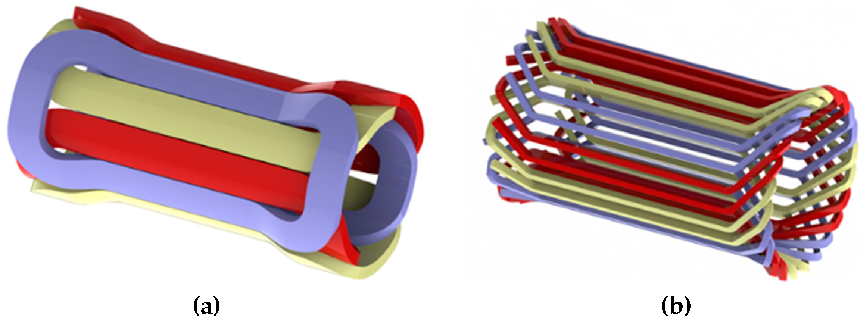
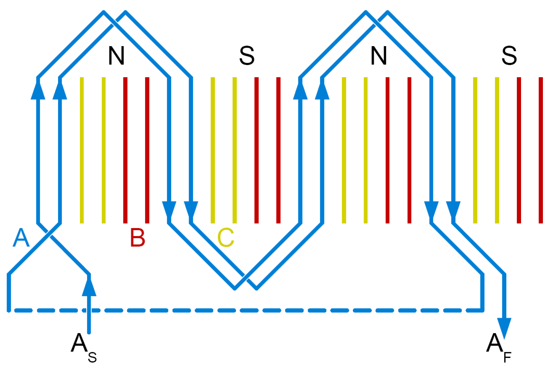
Figure 5. The lightweight SL layout on the left, and the more conventional DL layout on the right. The coil colors signify the three phases.
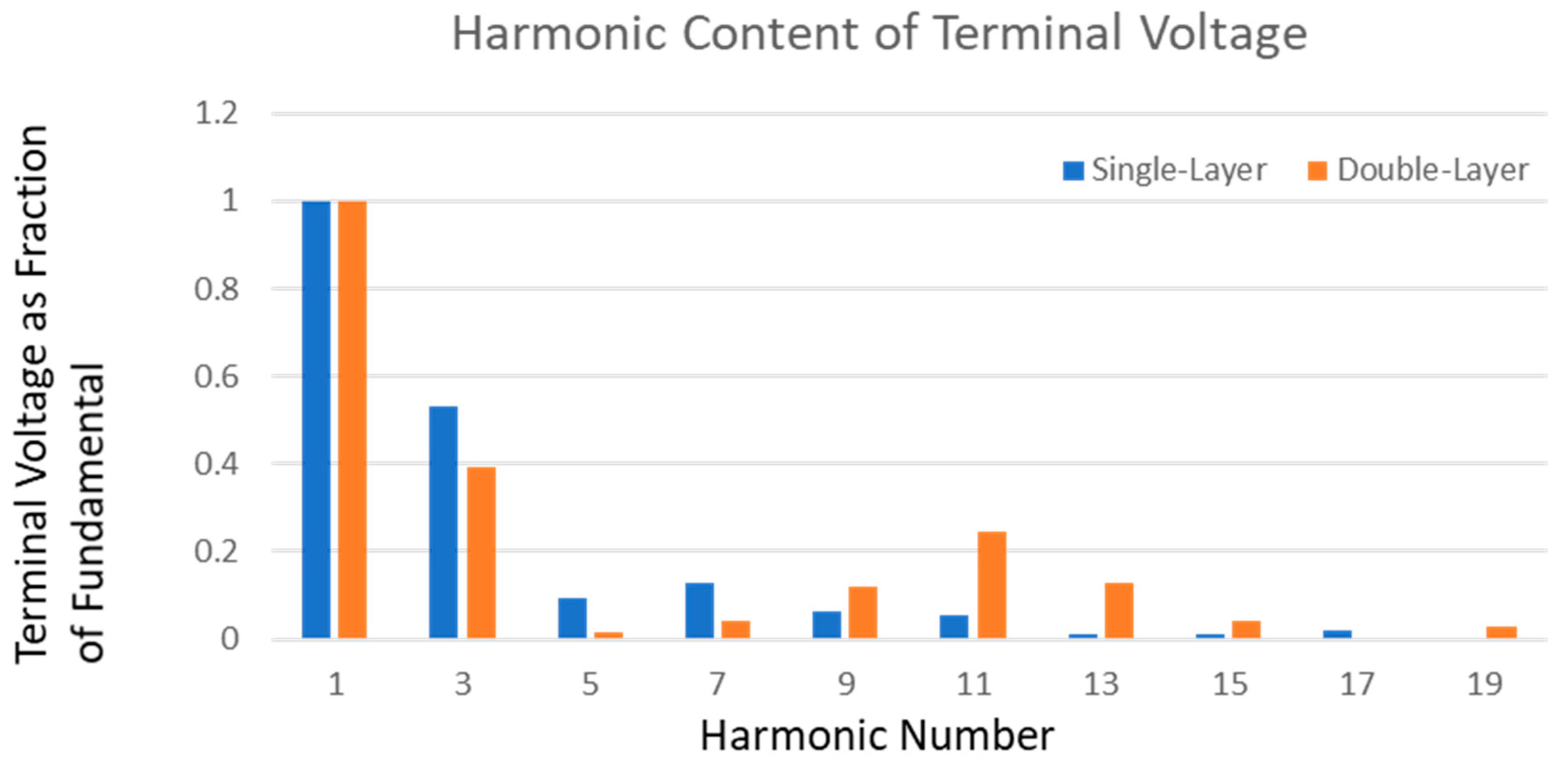
Harmonic content in the terminal voltage for the two types of windings is shown in
Figure 6. Overall, both SL and DL designs have similar harmonic contents. The 3rd, 9th, and 15th harmonics cancel out in a three-phase system. The 5th and 7th harmonics are larger for SL than DL design, but the 11th and 13th harmonics are smaller for the SL than the DL design. Nevertheless, harmonic contents in both designs appears to be within an acceptable range. However, during detailed design phase, poles will be shaped further to reduce harmonic contents, just as is customary for salient pole synchronous machines.
The 2D representations presented in
Figure 4 each display a single magnetic circuit enclosing the cross-sectioned superconducting exciter coil. As current in the coil travels into the page the magnetic flux travels around the coil in a clockwise direction, i.e., vertically upward through the rotor, to the left at the upper rotor lobe and into the stator, vertically downward through the stator, then to the right to re-enter the rotor at the lower rotor lobe. This 2D approximation was used in sizing the required iron components, however if the rotor lobes were aligned in this way the stator windings would experience zero net change in magnetic field along their length as the lobes passed.
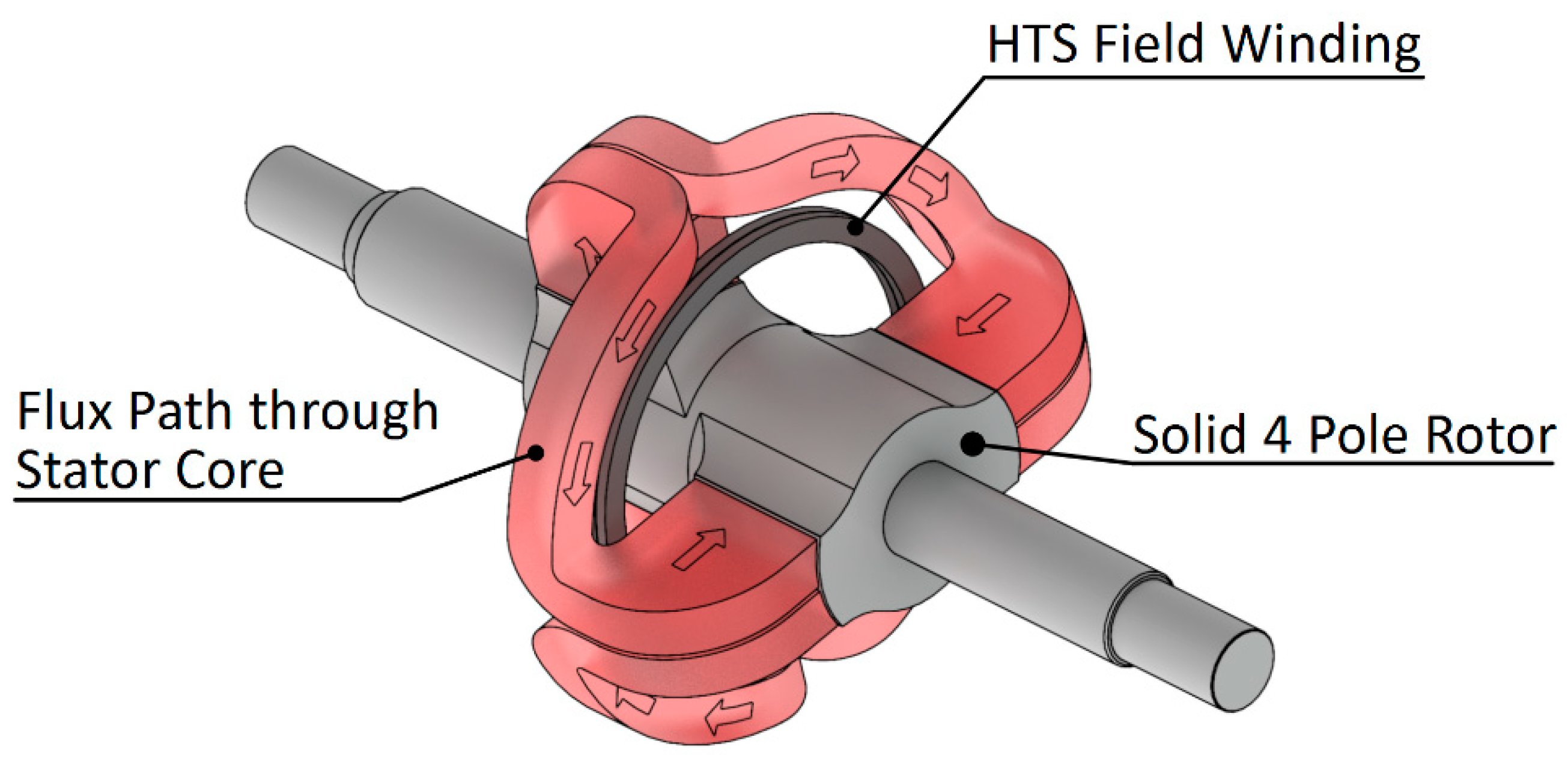
To ensure the stator windings experience an alternating magnetic field the rotor lobes are rotationally offset by 90 degrees, as illustrated in
Figure 1 and below in
Figure 7. This twists the magnetic circuit so each stator winding experiences a changing net magnetic field as the rotor lobes pass. The idealized magnetic circuit flux path is illustrated in red in
Figure 7. This path travels azimuthally through the central “bridge” section of the stator as supported by the concentric laminations of this part of the stator (
Figure 3).
Omitted from
Figure 7 for clarity, a small portion of flux lines also cross through the void-pole to the stator core. Each half of the stator core experiences maximum magnetic field under a solid-pole and minimum under a void-pole. Nevertheless, field under all pole, facing each ½ stator core is unidirectional.
Coils with straight sides (spanning the whole stator core) are employed for armature winding located in the stator.
Figure 4 shows the flux contours when each of the two configurations is salient. In this approximation the rotor poles are aligned with the stator core. This approximation is used for calculating the flux leakage through the interpole regions and stator. At any instant, an armature coil experiences maximum flux linkage (Φ
max) in the part of the stator aligned with the rotor pole, and minimum flux linkage (Φ
min) in the part of the stator aligned with the void pole. The net flux linkage (Φ
o) is the difference between these two values. The FEA code is utilized for calculating flux linkages in each half of the core. The net flux linkages are utilized for calculating induced voltage in a coil. Furthermore, location of Φ
max is identified as d-axis (solid-pole) and location of Φ
min is identified as q-axis (void-pole). The design analysis then assumes that the whole machine is represented by a half-core being acted upon by complete set of d- and q- poles, with Φ
o being experienced under each pole. On this basis, the induced voltage in an armature coil is as in Equation (1):
where:
Eo = induced voltage/coil (V)
c = proportionality constant
Φo = net flux linkage with a coil (Wb)
ωo = rotational frequency (rad/s)
The excitation field coil is circular in shape which makes it simple for construction. It is sized to provide necessary ampere-turns for excitation of the armature coils. The SL design has a larger effective air gap between the rotor and stator as it does not include iron teeth, this necessitates more ampere-turns than what is required in the DL design. Since this coil is sandwiched between two halves of stator iron core, it does not experience magnetic forces due to interaction with the armature winding current.
Figure 3 shows cross-section of the machine with locations of armature and field excitation coils. However, excitation coil side facing the armature winding experiences AC field due to currents in the armature coils. It is essential that this AC field be sufficiently attenuated for minimizing AC losses in the excitation coil. This is achieved by creating a separation between armature coils and excitation coils and installing an EM shield (copper or aluminum) to attenuate AC field experienced by the field coil. The location of the EM shield is identified in the
Figure 3. In this design analysis, the excitation coil employs ReBCO superconductor.
Preliminary design of the machines employing SL and DL armature windings are summarized in
Table 2. Both machines are sized to generate 500 kW at a three-phase line voltage of 830–900 V. Total ampere-turns needed for SL design are much larger than DL design due to significantly larger air gap in the SL design—this results in more turns in the field coil for SL design than the DL design. The SL machine is shorter in overall length and lighter than the DL machine. However, the DL machine is more efficient than the SL machine and uses much shorter length of ReBCO wire (185 m for SL versus 54 m for DL). This makes DL machine less costly to build than the SL machine. The table also lists preliminary component weights for the two machines; The DL machine weighs 27% more than the SL machine.
The DL design is preferable over the SL design if size and weight are not of concern. In the subway energy storage applications, the heavier, more efficient DL design is desirable as the motor is ground based at the subway station, sufficient space is available for the larger machine size, and high efficiency is desirable. For this machine design the superconducting material is the largest single component cost. In the SL design the expected superconductor cost is $39,000, while in the DL design much less superconductor is required, bringing the cost of the superconductor down to $4400. The superconductor cost for the SL design constitutes a large fraction of total expected cost of the machine, $100,000. The DL design is significantly more cost effective. Only the machine design employing the DL stator with ReBCO field coil is discussed further.
9. Performance Parameters
Table 4 includes parameters necessary for calculating machine performance under different loads and operating conditions as well as for interfacing it with inverters. Parameters are expressed in per-unit values; referenced to a base impedance of 1.39 ohm. Synchronous reactance of this machine is low due to the larger air-gap between rotor and stator. Small synchronous reactance is usually beneficial for stable operation of the machine on an electric grid. However, the small value also creates very large fault current during sudden short-circuit of the stator winding. Attention needs to be paid to this aspect during inverter design. No-load and full-load field currents are 278 A and 317 A, respectively. The field winding should be designed to carry 317 A with an Ic/Io of about 2. However, it must be noted that if the machine operating at full-load suddenly loses load, the armature voltage will rise to 1.14 pu (= 866 × 1.14 = 987 V-rms). Since it is difficult to change HTS field winding current rapidly, it would be necessary to modulate the voltage electronically in the inverter. In the event of a quench of the superconducting field winding, it would be necessary to extract its magnetic stored energy as rapidly as possible. The field winding will be shorted at its terminal through a 0.32 Ω discharge resistor—the maximum voltage imposed (during the discharging operation) on the field winding is limited to 100 V. The time constant for the discharge current is 3.0 ms.
Table 5 summarizes performance data for the machine calculated using 2D finite element analysis. The performance has been calculated for a full-load current of 360 A at a power-factor of 0.99 lagging. A more accurate value for power-factor would be based on the inverter design but the value selected here is conservative. The load angle with respect to the terminal voltage is 1.34°, which is quite small. However, in absence of a fixed terminal voltage, the value of load angle is of little interest
The nominal shaft torque for the machine is 208 Nm. But during short-circuit at the machine terminals, the torque will increase to 1487 Nm. Thus, it would be necessary to design the rotor shaft and the armature winding mechanical support to bear this torque with an acceptable safety margin, e.g., a safety factor of at least 2. Attractive forces between rotor and stator are 9282 N under a solid-pole and 246 N under the void-pole.
The
Table 5 also lists different loss components when the machine is carrying full-load. Stator core loss and armature winding resistive loss are two significant components. Cryogenic cooling system power is estimated to be 1.37 kW based on a refrigerator coefficient of performance (COP) of 21 at 50 K (COP is the ratio of power input to refrigerator to the heat power removed by the refrigerator). This COP value is obtained from Yuki Iwasa (MIT) book, 2nd Edition [
22]. A cooler system selected by a manufacturer may have different COP. Furthermore, thermal load calculations for the HTS coil might be different as they are a function of HTS coil type, its construction and interface with the room-temperature systems. Based on the assumptions made here, total loss at full-load is 4.4 kW, which yields an efficiency of 99.2%. This looks attractive at this conceptual design process and could be used as a goal to strive for.
It must be noted that this machine experiences significant losses under no-load operation. For example, if the field current is kept at its full-load operating value, the machine thermal load (cryo-cooler power) and core loss will remain unchanged and total loss would be 3.2 kW. However, if the field current is turned off during a prolonged no-load operation then the only loss component (cryo-cooler power loss) would be less than 1.36 kW. Thus, it would be necessary to turn off the field current when the flywheel is turning and storing energy for a long period of time. With contactless current transfer to the HTS coil, the above-mentioned 1.36 kW loss would be reduced to 30% (~0.4 kW).
10. Summary
For application of a ground-based fast energy storage system the DL concept looks attractive as compared with the SL design, which is more expensive due to the longer length of superconductor needed for the field winding. The DL solution is manufacturable using existing methods and technology, which will result in reduced construction time and cost, as well as shorter development time. The analysis presented here is based on employing ReBCO field coils, however, the comparison is equally valid for lower cost DI-BSCCO coils. DI-BSCCO coils are a commercially available technology with potential for further reducing development and construction time and cost. The concept design presented here is similar to a superconducting machine built and tested by General Electric [
16] and, therefore, the authors are sure about the feasibility of the presented machine. One of the authors was also part of a team that built and tested such a machine in about 1978 using copper field windings.
The design of a complete flywheel system suitable for fast energy recovery and delivery presents several challenges not within the scope of this paper. Magnetic bearings will be required to support the high rotational frequencies, as will a machine enclosure capable of holding partial vacuum to prevent significant windage losses. Design and development of flywheels and the machine shaft also present several challenges relating to the high rotational frequencies.
We are currently working towards manufacturing a demonstrator DL homopolar motor. As part of this process we will address flywheel construction and magnetic bearing design including the potential to use passive superconducting bearings.
