Article

Extraction of Temperature-Dependent Thermoelectric Material Parameters of a Thermoelectric Cooler by the Non-Linear Least Squares Method

1
The Institute of Optics And Electronics, The Chinese Academy of Science, Chengdu, Sichuan 610209, China
2
University of Chinese Academy of Science, Beijing 100149, China
*
Author to whom correspondence should be addressed.
Energies 2019, 12(1), 169; https://doi.org/10.3390/en12010169
Submission received: 4 December 2018 / Revised: 29 December 2018 / Accepted: 30 December 2018 / Published: 4 January 2019
(This article belongs to the Section I: Energy Fundamentals and Conversion)

Abstract

:
This paper presents a method of extracting temperature-dependent parameters of thermoelectric material from the operating conditions of thermoelectric cooler (TEC). Based on the finite element method of calculating TEC’s performance, non-linear least squares method is used for extracting temperature-dependent material parameters including the seebeck coefficient, electrical resistivity and thermal conductivity (α, ρ, κ) as operating current, thermal load and hot end temperature are taken as inputs and cooling temperature is taken as output. To further improve the voltage calculation accuracy, the electric resistance error factor which includes electrical contact resistance and the calculation model error is extracted with the voltage being output on the basis of extracted material parameters. The cooling temperature and voltage of another TEC with the same thermoelectric material are recalculated by the extracted parameters and the exact parameters provided by manufacturer respectively. Compared with the experimental results, the extracted material parameters have the advantages of high accuracy, wide application ranges and easily implementing in evaluating TECs’ performance.

1. Introduction

TEC is widely used in CCD cooling, precision temperature control and other fields because of its advantages such as no vibration, noiselessness, long life, no refrigerant and easy installation and so forth. Usually, TEC manufacturers provide a series of 1–5 stages TECs for customers to choose; and corresponding performance curves to facilitate customers to determine whether the selected TEC meets the application requirements. However, these performance curves are generally the curves when the hot end temperature is 27 °C and 50 °C, which often does not accord with the practical situation. Furthermore, there is often an error between these performance curves and experimental results; it always becomes bigger with the increase of the TEC’s stage. For example, for the five-stage TEC analyzed in this paper, the error of maximum temperature difference can be even up to 17 °C. Therefore, for most practical applications, it is difficult to evaluate the performance of TEC accurately only through the performance curves provided by manufacturers. For some special applications, TEC needs to be customized because of no suitable TEC products. Since the error of the performance curves provided by manufacturers is generally large, it is impossible for customers to determine whether the customized TEC can meet the requirements before experiment. In order to accurately evaluate the performance of TEC, amount of researches about the calculation model of TEC’s performance have been carried out [1,2,3]. Although parameters required in the calculation model can hardly be obtained from manufacturers, they can directly be measured. However, these measurements are not practical for customers due to cumbersome test process and the requirement of professional instruments [4,5,6]. These methods can only stay in theoretical stage for customers and are difficult to get actual application as a consequence. Therefore, establishing a simple, practical and effective TEC parameters extraction method is crucial to the performance evaluation of TEC.
Some researchers did a lot of research on the extraction methods of TEC parameters. The extracted parameters can be divided into module parameters and material parameters. In Reference [7,8,9,10], extreme values ∆Tmax, Imax, Vmax, Qmax in datasheet were used to extract the module parameters for one-stage TEC. Luo et al. [7] calculated two groups module parameters of four different TECs using the extreme values ∆Tmax, Imax, Vmax and ∆Tmax, Imax, Qmax respectively. The study showed the errors of two groups’ module parameters for the same TEC were less than 5% but different TECs had completely different module parameters. Tan et al. [8] studied the application range of the method of extracting module parameters using extreme values, the extracted module parameters were applicable to one-stage and two-stage TECs and it became worsen for more stages TECs. Zhang et al. [9] confirmed that the extracted module parameters had the same accuracy with the iteration method using material parameters for one-stage TEC. Ben-Yaakov et al. [10] recalculated the cooling temperature and voltage using the module parameters extracted by extreme value; and the results were almost identical to the ones given in the datasheet. Palacios et al. [11] extracted module parameters by taking multiple points from performance curves to reduce the error and the performance analyzed with extracted module parameters was verified accord with experimental results when TEC was used as thermoelectric power generation. Dziurdzia et al. [12] used the software provided by Laird Technologies, Inc (Saint Louis, MO, USA), the temperature difference between the hot and cold ends was set to 0K at different hot end temperatures and the change of the module electric resistance with temperature was calculated by the relationship between voltage and current, the seebeck coefficient and thermal conductivity were calculated by the same way.
Since there is an error between the data provided by manufacturers and the experimental results, it is necessary to actually test the working condition of the TEC during operation to obtain more accurate parameters for TEC’s performance calculation under practical operation. Reference [13,14] designed different experimental systems to provide different temperatures for the two ends of TEC and then measured the output voltage or current to determine the module parameters, respectively. Huang et al. [13] tested module parameters with temperature range of 0–30 °C and the measured module parameters were approximated as a linear relationship of temperature due to the small temperature range. Anatychuk et al. [14] measured module parameters with temperature range of 30–600 °C and could be developed to 800 °C, good results were obtained in the performance calculation when TEC was used as power generation. Reference [15,16,17] extracted module parameters by measuring the change of voltage when the TEC current changed instantaneously and the extracted parameters were regarded as the value of the average temperature of the hot and cold end. Mitrani et al. [15] tested module parameters with the instantaneous output voltage at the moment current was interrupted when TEC was at steady state and the module parameters were approximately linear relationship of temperature in the range of 6–21 °C for the temperature range was too small. Ahiska et al. [16] built a fully automatic system for testing the transient condition at the moment current was interrupted for steady-state TEC, which greatly improved work efficiency. Chu et al. [17] tested the transient voltage and temperature when the TEC was applied a constant current suddenly and then extracted module parameters.
The module parameters are the macro parameters of the entire TEC and can be used for performance analysis when TEC is used in non-standard applications. However, module parameters contain the information about size, number of thermoelectric couples and contact resistance, so, they are no longer applicable to another different TEC. In order to make the extracted parameters have a wider range of applications, Reference [18,19] extracted material parameters as constant by extreme values supplied by manufacturers. Chen et al. [18] showed that the error of the maximum temperature difference was 2.85% when it was recalculated using the extracted material parameters and the relative error of voltage varied from 3% to 20%. Weera et al. [19] also showed that the recalculated performance was nearly the same as that provided by manufacturer. Since the temperature difference of one-stage TEC is relatively small, the extracted parameters which are viewed as constant have high accuracy for the recalculation of one-stage TEC. In fact, these parameters vary with temperature and the performance of the thermoelectric material deteriorates with temperature reduction. Therefore, considering material parameters as constant cannot satisfy the situation at any cooling temperature, especially for multi-stage TECs which have lower cooling temperature. In summary, there is currently scarcely a simple way to obtain the thermoelectric parameters which are effective and can be used extensively.
In this study, a new method of extraction of three temperature-dependent thermoelectric material parameters has been developed. Under the premise of finite element analysis being verified with high accuracy for calculating cooling temperature, non-linear least squares method is used to extract material parameters. To further improve the calculation accuracy of voltage, the electric resistance error is analyzed by extracting the electric resistance error factor varying linearly with temperature. When the material parameters extracted from one TEC are used to calculate another TEC’s performance, the result has high accuracy, which means the extracted material parameters can effectively characterize the property of thermoelectric material.

2. Modeling and Experiments

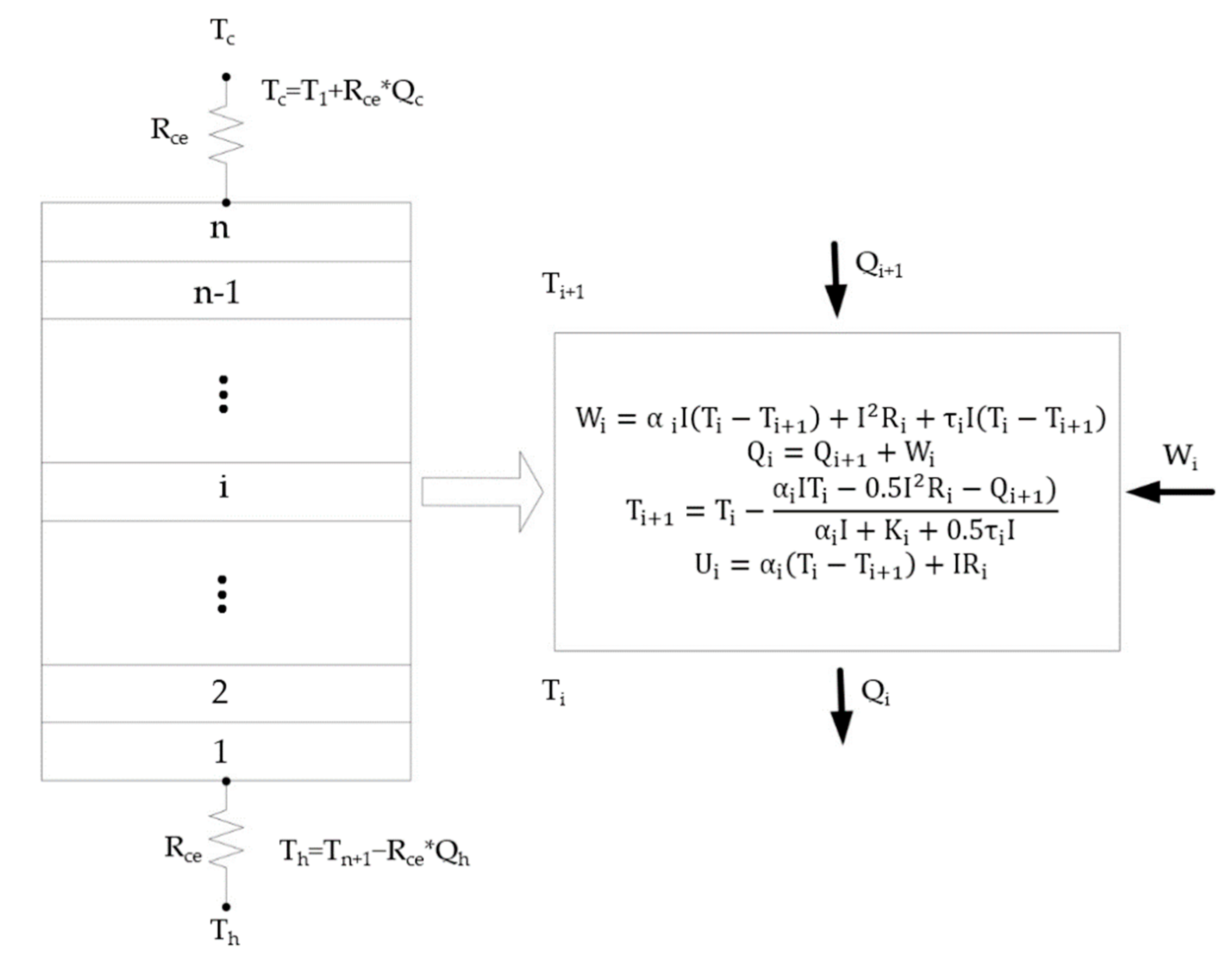
2.1. Method of TEC performance

According to the basic thermoelectric equation, the cooling capacity, power consumption, heat dissipation and voltage of a thermoelectric couple are follows:
Q c   =   α IT c     0 . 5 I 2 R   -   K Δ T     0 . 5 τ I Δ T ,
W   =   α I Δ T   +   I 2 R   +   τ I Δ T   ,
Q h   =   Q c +   W   =   α IT h   +   0 . 5 I 2 R     K Δ T   +   0 . 5 τ I Δ T ,
U   =   α Δ T   +   IR ,
where α IT c , α I Δ T , α IT h are caused by thermoelectric effect, I2R represents Joule effect, K Δ T is heat conduction effect, τ I Δ T represents Thomson effect respectively. R, K and τ are defined as: R   =   ρ L / A , K   =   κ A / L , τ   =   Δ α Δ T T .
In order to consider the relationships between material parameters and temperature, the method of finite element analysis with high accuracy is used for theoretically calculation of the TEC performance in vacuum [20,21]. One-dimensional model is chosen for the finite element analysis of TEC. Its meshing strategy is shown in Figure 1:
Divide the leg into n units, if n is large enough, parameters of each unit can be regarded as constant. For the ith unit:
W i = α i I ( T i - T i + 1 ) + I 2 R i + τ i I ( T i - T i + 1 ) ,
Q i = Q i + 1 + W i ,
T i + 1 = T i - α i IT i - 0 . 5 I 2 R i - Q i + 1 α i I + K i + 0 . 5 τ i I ,
U i = α i ( T i - T i + 1 ) + IR i ,
Tc and Tn+1 and U can be calculated by the following formulas
T c   =   T 1 + R ce Q c ,
T n + 1   =   R ce Q n + 1 + T h ,
U   =   i = 1 n U i ,
If the parameters α , ρ , κ are known and Th is determined, for the determined Qc, the iteration of Equations (5)–(11) can be used to calculate the values of Tc and U.

2.2. Extraction Method of Thermoelectric Material Parameters

Thermoelectric materials parameters can be expressed as quadratic polynomial of temperature empirically [6], According to the analysis in Section 2.1, if coefficients ( a i ,   b i ,   c i ,   i   =   1 , 2 , 3 ) in Equations (12)–(14) are known, then the relationships between α , ρ , κ and T can be obtained.
α   =   a 0 + a 1 T + a 2 T 2 ,
ρ   =   b 0 + b 1 T + b 2 T 2 ,
κ   =   c 0 + c 1 T + c 2 T 2 ,
Then Tc can be written as
T c = f ( I , Q c , T h , a 0 , a 1 , a 2 , b 0 , b 1 , b 2 , c 0 , c 1 , c 2 ) ,
where, I, Th, Tc can be directly measured, Qc is the applied thermal load, the function relationship f is determined in Section 2.1, Therefore, the extraction of material parameters can be transformed into the solution of the non-linear least squares problem.
In order to decide the upper and lower limits of material parameters, Figure 2 shows the parameters of three different thermoelectric materials with respect to temperature. In handbook [6], material parameters of a bismuth-telluride sample were tested. [22] provides relevant parameters of bismuth-telluride from company Melcor, USA. [23] is the parameters of bismuth-telluride used by company Namic, China. The coefficients are given in Table 1. The parameters are the average of p and n legs, respectively.
According to Table 1, the coefficients of three materials parameters vary greatly, which is difficult to intuitively reflect the values and trend of the parameters. Thus, it is not convenient to determine the upper and lower limits and constraints of the coefficients. Although the parameters of different thermoelectric materials are different, almost all of them adopt bismuth telluride compounds, except that the composition ratio and doping elements are different. According to Figure 2, the parameters have a consistent trend with temperature and the values are close. In order to facilitate the initial values and determine the upper and lower limits and constraints, Equations (12)–(14) are rewritten as the following format:
α   =   [ α 200 ( T - 250 ) ( T - 300 ) + α 300 ( T - 250 ) ( T - 200 ) - 2 α 250 ( T - 200 ) ( T - 300 ) ] / 5000 ,
ρ = [ ρ 200 ( T - 250 ) ( T - 300 ) + ρ 300 ( T - 250 ) ( T - 200 ) - 2 ρ 250 ( T - 200 ) ( T - 300 ) ] / 5000 ,
κ = [ κ 200 ( T - 250 ) ( T - 300 ) + κ 300 ( T - 250 ) ( T - 200 ) - 2 κ 250 ( T - 200 ) ( T - 300 ) ] / 5000 ,
where the subscripts 200, 250, 300 of α ,   ρ ,   κ are temperature with unit K. Then Equation (15) can be written as:
T c = f ( I , Q c , T h , b ) ,
where   b   =   ( α 200 , α 250 , α 300 , ρ 200 , ρ 250 , ρ 300 , κ 200 , κ 250 , κ 300 ) .
According to Figure 2, the nine coefficients in Equations (16)–(18) meet the following constraints.
10 4   <   α 200   <   α 250   <   α 300   <   5   ×   10 4 ,
2   ×   10 6   <   ρ 200   <   ρ 250   <   ρ 300 <   2   ×   10 5 ,
2 . 5   >   κ 200   >   κ 250   >   κ 300   >   1   ,
In order to reduce the influence of measurement error so that the extracted parameters are more effective, different working conditions of TEC have been tested. For three different thermal loads Qc1, Qc2, Qc3, three sets of cooling temperature Tc1, Tc2, Tc3 with each set containing m different currents are tested. Define Tsum = [Tc1,Tc2,Tc3] and the corresponding calculated cooling temperature as f 1 ( I , Q c 1 , T h 1 , b ) , f 2 ( I , Q c 2 , T h 2 , b ) f 3 ( I , Q c 3 , T h 3 , b ) , f sum ( I , Q c 1 , Q c 2 , Q c 3 , T h 1 , T h 2 , T h 3 , b )   =   [ f 1 , f 2 , f 3 ] . Initial value is given by b0 = ( α 200 0 , α 250 0 , α 300 0 , ρ 200 0 , ρ 250 0 , ρ 300 0 , κ 200 0 , κ 250 0 , κ 300 0 ) . Then, the Taylor expansion of fsum at b0 with high-order items omitted can be expressed as
f sum ( I i , Q c 1 , Q c 2 , Q c 3 , T h 1 i , T h 2 i , T h 3 i , b )   =   f sumi + j = 1 9 f sumi b j ( b j     b j 0 )   ,
where f sumi   =   f sum ( I i , Q c 1 , Q c 2 , Q c 3 , T h 1 i , T h 2 i , T h 3 i , b 0 ) , then the sum of squared residual of fsum and experimental value Tsum is
S ( b )   =   i = 1 3 m [ T sumi     ( f sumi + j = 1 9 f sumi b j ( b j     b j 0 ) ) ] 2 ,
Define z j = b j   b j 0 (j = 1,2…9), z = ( z 1 , z 2 , , z 9 ) , then
S ( b )   =   i = 1 3 m [ T sumi     ( f sumi + j = 1 9 f sumi b j z j ) ] 2 ,
The derivative of bj with respect to S is
S b j   =   S z j   =   2 j = 1 9 [ T sumi     ( f sumi + j = 1 9 f sumi b j z j ) ] [ f sumi b j ] ,
According to the principle of least squares, when S(b) is the minimum value, S b j =   0 ,   j   =   1 , 2 , 9 , therefore
i = 1 3 m f sumi b j [ j = 1 9 f sumi b j z j ] = i = 1 3 m ( T sumi     f sumi ) f sumi b j ,   j   =   1 , 2 , n   ,
Define a ij =   f sumi b j , then
A = ( a ij ) = [ f sum 1 b 1 f sum 1 b 2 f sum 2 b 1 f sum 2 b 2 f sum 1 b 9 f sum 2 b 9 f sum 3 m b 1 f sum 3 m b 2 f sum 3 m b 9 ] ,
bj used in next iteration process is
b j = inv ( A   ' ×   A )   ×   A   ' ×   ( T sum     f sum ) + b j 0 ,
By iterating over bj, the value of b minimizing the sum of the squares residual can be obtained, which is the required thermoelectric material parameters.

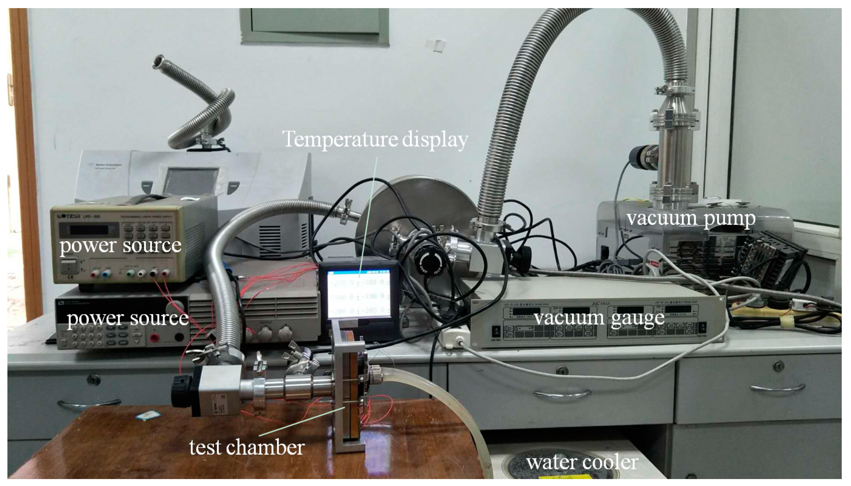
2.3. Experiment Platform for TEC Performance

In order to determine the inputs and outputs in Section 2.2, the experiment platform shown in Figure 3 is designed. In Figure 3, the test chamber is sealed with a rubber ring and is connected to vacuum pump. The internal pressure is monitored by vacuum gauge. The two power sources supply DC power for the TEC and the heater that attached to the cold end of TEC as thermal load. Pt1000 thermocouple sensors whose accuracy is ± 0 . 1   ° C are respectively arranged at the cold and hot end of the TEC to measure Tc and Th, which can be read directly from temperature display. The heat dissipated on the hot end is carried away by water cooler, all electrical signals transmit by feedthroughs.

3. Simulation and Experimental Results

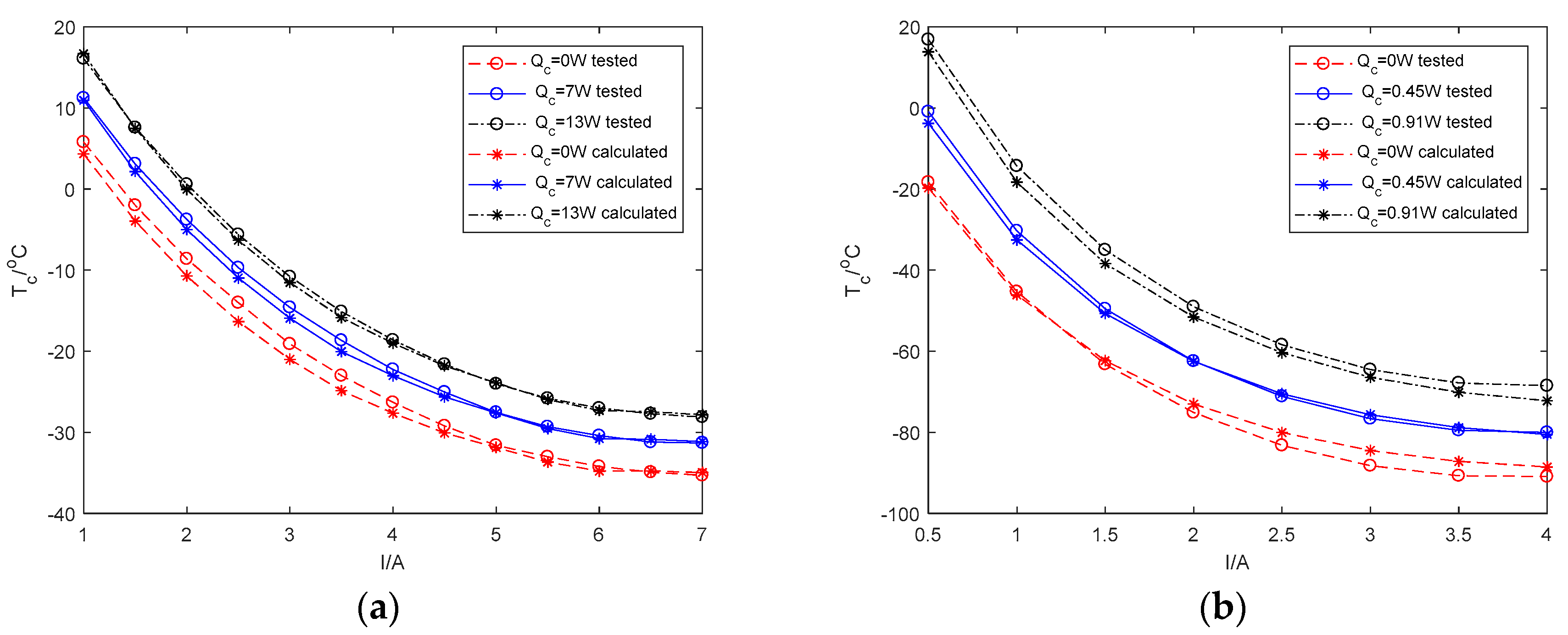
3.1. Verification of the Accuracy of Calculation Model for TEC Performance

Cooling temperature and power consumption are the main considerations in the selection of TEC. The cooling temperature and voltage of two TECs produced by Namic, China are calculated by iterating Equations (5)–(11). A one-stage TEC named TEC1-19908 and a five-stage TEC named TEC5-127-71-31-17-08-04 are used. The calculation results are presented in Figure 4 and Figure 5, respectively.
For one-stage TEC, cooling temperature and voltage are tested with current varies from 1 A to 7 A when thermal loads are 0 W, 7 W and 13 W respectively. For the five-stage TEC, cooling temperature and voltage are tested with current varies from 1A to 4A when thermal loads are 0W, 0.45 W and 0.91 W respectively. The comparison between the calculated results and the tested results of cooling temperature and voltage are also shown in Figure 4 and Figure 5 respectively.
According to Figure 4, for the one-stage TEC, the biggest absolute errors of Tc at Qc = 0 W, 7 W, 13 W are 2.33 K, 1.34 K, 0.75 K, which are 3.43%, 2.00%, 1.18% of the maximum ΔT respectively. For the five-stage TEC, the biggest absolute errors of Tc at Q c= 0 W, 0.45 W, 0.91 W are 3.74 K, 2.89 K, 4.00 K, with 3.14%, 2.68%, 4.13% of the maximum ΔT respectively. The Tc at Qc = 0W given by the manufacturer are −43 °C and −108 °C for the one-stage and five-stage TECs respectively and the corresponding absolute errors are 7.70K and 17.10K, with 11.34% and 14.36% of the maximum ΔT respectively. It can be seen that finite element method has a high accuracy for calculating the cooling temperature of TEC in vacuum.
Figure 5 shows that the voltage at different thermal loads are nearly the same. The voltage error becomes bigger with the increase of current. For the one-stage TEC, when I = 7 A, it has the biggest absolute error of 2.00 V and the biggest relative error of 8.91%. The biggest absolute and relative errors of the five-stage TEC are 2.66 V and 18.41% at I = 4A, respectively. It can be seen that for the calculation of voltage, the accuracy of the calculation model is not very well, which is why the voltage is not included in the output in Section 2.2. The voltage error is caused by factors such as the calculation model error, electrical contact resistance, electrical resistance of wires and so forth. Despite different effects of various factors on the voltage, all the factors can be regarded as an equivalent electric resistance error.

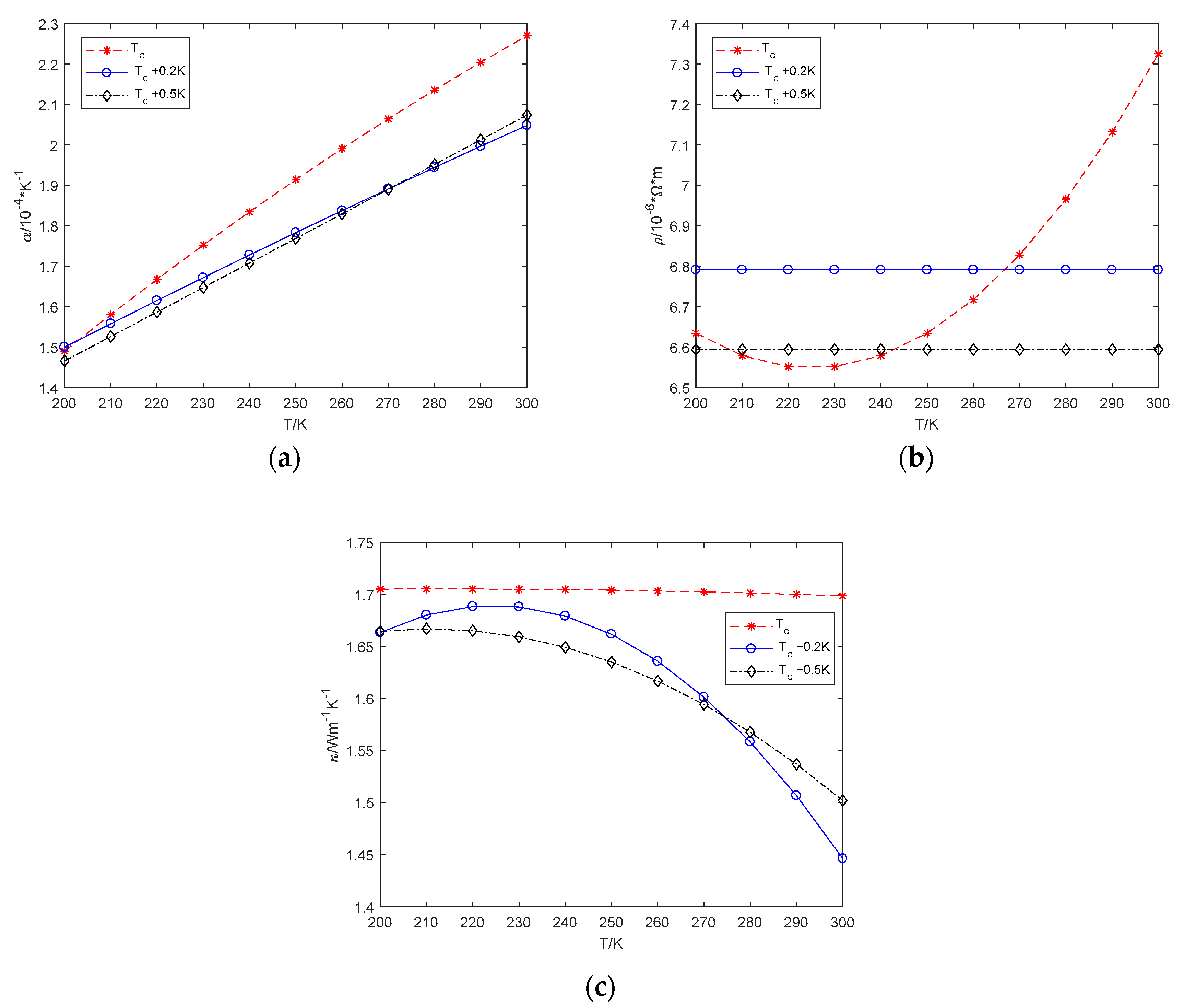
3.2. Accuracy of the Extracted Material Parameters

In order to obtain effective material parameters so that it can be used for TEC design and optimization, experimental results obtained in Section 3.1 are used to extract material parameters by non-linear least squares method in this section. The comparison between the extracted results and the exact material parameters used by the manufacturer are given in Figure 6.
According to Figure 6, the errors between the extracted and the exact parameters are very large, so the extracted parameters cannot be regarded as the exact parameters. The factors that cause this phenomenon are mainly the following aspects. First, there is an error between the calculation model and the actual situation. The heat leak from the surrounding environment and the contact resistance produced by the welding of thermoelectric couples are neglected in the calculation model. The heat conduction on the inter-stage ceramics for each thermoelectric couple is regarded the same in the calculation model which is not realistic in practice owing to the pagoda structure of the multi-stage TEC. The same situation can be found for the temperature distributions of the p-leg and n-leg. The second is the measurement errors, including the size error of the thermoelectric couple and the error of the temperature measurement at the hot and cold ends end.
If the calculation model is completely the same with the actual situation, for a set of accurate measurement of Th, Tc and Qc, it is inevitable to extract completely correct parameters. However, accurate measurement of Tc alone is often difficult, provided that the model in Section 2.1 is completely correct. The temperature measurement error is generally 0.2 K–0.5 K on condition of repeated measurement. After the TEC is reassembled and measured again, the error is even larger, which can be up to 2 K. Therefore, it is impossible to ensure that the error between the measured results and actual value is sufficiently small. Figure 7 shows the parameters extracted using cooling temperature with a deviation of +0 K, +0.2 K and +0.5 K for the one-stage TEC. According to Figure 7, even if tested Tc has a deviation of +0.2 K, the obtained parameters are far from the exact values.
For the finite element model described in Section 3.1, the biggest error of the calculated Tc is more than 2 K (see Figure 4). So the parameters obtained by this method are difficult to be regarded as exact values. However, since the TEC’s performance is determined by these three parameters together, according to Figure 4, the comprehensive performance of the material determined by the three extracted parameters necessarily has an approximate performance with the exact parameters. Only in this way, the calculated results will be approximate to the experimental values (experimental values can be regarded as calculated by extracted parameters).

3.3. Verification of the Validity of the Extracted Parameters

This section verifies whether the extracted parameters can be used to calculate the TEC performance instead of the exact parameters.
To verify the validity of the parameters extracted in Section 3.2, the cooling temperature and voltage of the five-stage TEC are recalculated with Qc = 0 W, 0.45 W and 0.91 W using the parameters extracted from the one-stage TEC, respectively. In reserve, the cooling temperature and voltage of the one-stage TEC are recalculated with Qc = 0 W, 7 W and 13 W using the parameters extracted from the five-stage TEC, respectively. The comparison between the recalculated Tc and experimental results is shown in Figure 8.
According to Figure 8(a), for the one-stage TEC, the biggest absolute errors of the recalculated Tc at Qc = 0 W, 7 W, 13 W are 2.92 K, 2.68 K, 3.72 K, which are 0.59 K, 1.34 K, 2.97 K higher than those of the calculated Tc (see Figure 4a), respectively. In fact, as TEC always works with current between the maximum coefficient of performance (COP) and maximum ΔT, so the errors of recalculated Tc at working situation will be smaller. For example, when I = 5 A, the errors of recalculated Tc are just 1.35 K, 1.51 K, 2.75 K respectively. For the five-stage TEC (see Figure 8b), the biggest absolute errors of the recalculated Tc at Qc = 0 W, 0.45 W, 0.91 W are 2.18 K, 1.44 K, 3.52 K, which are 1.56 K, 1.45 K, 0.48 K smaller than those of the calculated Tc (see Figure 4b), respectively. This shows that the recalculated Tc have almost the same accuracy with Tc calculated by exact parameters, so the extracted material parameters can replace the exact material parameters in calculating Tc of TEC.
Because of the heat dissipation at hot end of TEC should also be considered in TEC’s selection, voltage across the TEC needs to be evaluated. The comparison between the recalculated U and experimental results is shown in Figure 9. According to Figure 5 and datasheets provided by manufactures, voltage for different Qc are very close. Therefore, Figure 9 only shows the voltage when Qc = 0 W. For both calculated and recalculated voltage, as the current increases, the voltage error becomes larger. For the one-stage TEC, the relative error of calculated voltage reaches up to 8.47% at I =7 A. For the five-stage TEC, the relative error of calculated voltages reaches up to 17.27% at I = 4 A. Since calculated voltages are lower than the experimental values, the calculated maximum heat dissipation requirement will be smaller than the actual requirement, especially for the five-stage TEC. Because of the error of calculated voltage is relatively large, the extracted parameters are relatively ineffective for voltage calculation. Therefore, the designed heat sink will probably not meet the demand. In this regard, an electric resistance error factor which indicates the error of calculated for voltage must be considered to obtain a more accurate calculated voltage.
For both of the one-stage and five-stage TECs, the three voltages are approximated the quadratic polynomial function of current in Figure 9, which is more obvious in Figure 9b. Then the absolute errors of voltages can be written as Δ U   =   aI 2   +   bI and the absolute error of electric resistance can be written as Δ R   =   aI   +   b . Since different currents correspond to different cooling temperatures, so the electric resistance error is temperature-dependent. According to Figure 9a and Figure 4a, the relationship between the total electric resistance error of the one-stage TEC and cooling temperatures is shown in Figure 10. R is approximately linear to Tc which can be expressed as R   =   kT + R 0 (k > 0). In order to evaluate the voltages more accurately, the tested voltages are taken as the output in Section 2.2. An electric resistance error factor linear to T is applied to the leg of the thermoelectric couple to correct the voltage error.
Figure 11 shows the voltage versus current of the one-stage TEC and the five-stage TEC, which are calculated and recalculated when considering electric resistance error. For the one-stage TEC, when I > 5.5 A, the recalculated voltage error is smaller if electric resistance error is considered. The relative error of the recalculated voltage decreases as the current increases. When I < 5.5 A, the recalculated voltage error deteriorates when electric resistance error is considered. When I = 3.5 A, the recalculated voltage error has a maximum relative error of 7.57%. When the electric resistance error factor is extracted from the five-stage TEC, the voltage accuracy of a larger range of Tc is taken into account. Hence, it is reasonable that the voltage accuracy of the one-stage TEC will become worse when voltage accuracy with a small temperature range is deteriorated.
For the five-stage TEC, both the calculated and the recalculated voltage are significantly improved when electric resistance error is considered. Although the relative errors of the recalculated voltage are 10.33% and 5.93% at I = 0.5 A and 1 A, respectively, the absolute errors of the corresponding voltage are only 0.26 V and 0.27 V, respectively. When I > 1 A, the maximum relative error of the recalculated voltage is only 2.33%, which occurs at I = 1.5 A. On the whole, when the electric resistance error is considered, the recalculated voltage can be improved and voltage of different series TEC can be better taken into consideration.
Since NAMIC Corp., Ltd. does not provide software to calculate TEC performance, therefore, the method in Reference [12] cannot be implemented. At the same time, the experimental equipment used to maintain the TEC for a series of a certain temperature in Reference [13,14] was complicated and instantaneous current change also needs to maintain the TEC for a series of a certain temperature. This is what the experimental platform of this article cannot do. Therefore, the article is only compared with the extracting method by extremum values in Reference [19]:
Z = 2 Δ T ( T h Δ T max ) 2 ,
  α = 2 Q max nI max ( T h + Δ T max ) ,
ρ = α ( T h T max ) A / L I max ,
κ = α 2 ρ Z ,
The material parameters extracted by Equations (30)–(33) for the one-stage TEC are:
α = 2.13 e     4 V / K
ρ = 8.62 e     6 Ω × m
κ = 2.02 W / ( m × K )
The recalculated Tc and U of the five-stage TEC are shown in Figure 12.
According to Figure 12a, the biggest absolute errors of the recalculated Tc by method in Reference [19] at Qc = 0 W, 0.45 W, 0.91 W are 10.01 K, 11.65 K, 13.48 K, respectively, which are only 2.18 K, 1.44 K, 3.52 K for the method proposed in this paper. The biggest relative error of recalculated voltage by method in Reference [19] is 10.56%, it is also higher than 2.33% that recalculated by this paper.
It can be seen that the accuracy is high when the material parameters extracted from one TEC by the method proposed in this paper are applied to evaluate the performance of another TEC of the same material with different stages and sizes. In the case where the true parameters cannot be obtained, the extracted parameters can be used to calculate the performance of the TEC as the effective substitute. In this way, by the experiment of a one-stage TEC (usually one-stage TEC is mostly supplied by manufacturers), parameters can be extracted and then, used for the performance analysis of other TECs of the same material for any structure and structural optimization for special requirement. Therefore, the right TEC can be effectively selected or customized.

4. Conclusions

A method of extracting thermoelectric material parameters, including seebeck coefficient, electrical resistivity, thermal conductivity, is proposed in this paper. This method only needs to test the cooling temperature of the TEC under different currents in vacuum and there is no strict requirement for other aspects. The extracted parameters are temperature-dependent and quadratic polynomials of temperature. The cooling temperatures of the one-stage and five-stage TECs are recalculated using the material parameters extracted from the five-stage and the one-stage TECs, respectively. And the recalculated results verified have high accuracy, which means the extracted parameters can well characterize the comprehensive performance of the thermoelectric material throughout the TEC operating temperature range. In addition, the temperature-dependent electric resistance error of thermoelectric legs is analyzed and extracted. The accuracy of the recalculated voltage is greatly improved when the electric resistance error is considered. The extracted material parameters can completely replace the exact material parameters for the calculation of TEC performance. This paper provides a very useful method for TEC application engineers to accurately determine the actual performance of TEC during the TEC selection and to optimize the dimensional parameters in the customization.

Author Contributions

All authors contributed to this work. S.N. carried out the modeling and calculations. X.G. and S.N. provided the original idea and analyzed the simulation results. M.W., S.N. and J.L. supplied the original data of case study and revised the manuscript. All authors have read and approved the final manuscript.

Funding

This research received no external funding.

Acknowledgments

This work was supported by Institute of Optics and Electronics of Chinese Academy of Science, China.

Conflicts of Interest

The authors declare no conflict of interest.

Nomenclature

Qccooling capacity (W)
Qhheat dissipation of hot end (W)
WPower consumption (W)
Ielectric current (A)
Tccold side temperature (K or °C
Thhot side temperature (K or °C)
Δ Ttemperature difference across the TEC (K or °C)
Aleg cross-sectional area(m2)
Lleg length (m)
Uvoltage (V)
Kthermal conductance (WK−1)
Relectric resistance ( Ω )
Rcethermal resistance of ceramic ( Ω )
QiHeat dissipation of ith element (W)
WiPower consumption of ith element (W)
α seebeck coefficient (VK−1)
ρ electrical resistivity ( Ω · m)
κ thermal conductivity (W m−1 K−1)
τ Thomson coefficient (V K−1)
Kithermal conductance of ith element (WK−1)
Rielectric resistance of ith element ( Ω )
α i seebeck coefficient of ith element (VK−1)
ρ i electrical resistivity of ith element (Ω m)
κ i thermal conductivity of ith element (W m−1 K−1)
τ i Thomson coefficient of ith element (V K−1)
T i temperature of ith element (K or °C)
Ttemperature (K or °C)

References

  1. Fraisse, G.; Ramousse, J.; Sgorlon, D.; Goupil, C. Comparison of different modeling approaches for thermoelectric elements. Energy Convers. Manag. 2013, 65, 351–356. [Google Scholar] [CrossRef]
  2. Wang, T.H.; Wang, Q.H.; Leng, C.; Wang, X.D. Parameter analysis and optimal design for two-stage thermoelectric cooler. Appl. Energy 2015, 154, 1–12. [Google Scholar] [CrossRef]
  3. Karimi, G.; Culham, J.R.; Kazerouni, V. Performance analysis of multi-stage thermoelectric coolers. Int. J. Refrig. 2011, 34, 2129–2135. [Google Scholar] [CrossRef]
  4. Hejtmánek, J.; Knížek, K.; Švejda, V.; Horna, P.; Sikora, M. Test system for thermoelectric modules and Materials. J. Electron. Mater. 2014, 43, 3726–3732. [Google Scholar] [CrossRef]
  5. Kallaher, R.L.; Latham, C.A.; Sharifi, F. An Apparatus for Concurrent Measurement of Thermoelectric Material Parameters. Rev. Sci. Instrum. 2013, 84, 1457. [Google Scholar] [CrossRef] [PubMed]
  6. Buist, R.J. Thermoelectric Material Parameters. In CRC handbook of thermoelectrics, 4th ed.; Rowe, D.M., Ed.; CRC press: Traverse City, MI, USA, 1995; chapter 14.3. [Google Scholar]
  7. Luo, Z. A simple method to estimate the physical characteristics of a thermoelectric cooler from vendor datasheets. Electron. Cooling 2008, 14, 22–27. [Google Scholar]
  8. Tan, F.L.; Fok, S.C. Methodology on sizing and selecting thermoelectric cooler from different TEC manufacturers in cooling system design. Energy Convers. Manag. 2008, 49, 1715–1723. [Google Scholar] [CrossRef]
  9. Zhang, H.Y. A general approach in evaluating and optimizing thermoelectric coolers. Int. J. Refrig. 2010, 33, 1187–1196. [Google Scholar] [CrossRef]
  10. Lineykin, S.; Ben-Yaakov, S. Modeling and Analysis of Thermoelectric Modules. IEEE Trans. Ind. Appl. 2007, 43, 505–512. [Google Scholar] [CrossRef] [Green Version]
  11. Palacios, R.; Arenas, A.; Pecharromán, R.R.; Pagola, F.L. Analytical procedure to obtain internal parameters from performance curves of commercial thermoelectric modules. Appl. Therm. Eng. 2009, 29, 3501–3505. [Google Scholar] [CrossRef] [Green Version]
  12. Dziurdzia, P.; Bratek, P.; Brzozowski, I.; Gelmuda, W.; Ostrowski, J.; Kos, A. Extraction of temperature dependent parameters for an electrothermal model of thermoelectric energy harvester. In Proceedings of the 2016 MIXDES—23rd International Conference Mixed Design of Integrated Circuits and Systems, Łódź, Poland, 23–25 June 2016; pp. 377–381. [Google Scholar] [CrossRef]
  13. Huang, B.J.; Chin, C.J.; Duang, C.L. A design method of thermoelectric cooler. Int. J. Refrig. 2000, 23, 208–218. [Google Scholar] [CrossRef]
  14. Anatychuk, L.I.; Havrylyuk, M.V. Procedure and Equipment for Measuring Parameters of Thermoelectric Generator Modules. J. Electron. Mater. 2011, 40, 1292–1297. [Google Scholar] [CrossRef]
  15. Mitrani, D.; Tome, J.A.; Salazar, J.; Turo, A.; Garcia, M.J.; Chavez, J.A. Methodology for extracting thermoelectric module parameters. IEEE Trans. Instrum. Meas. 2005, 54, 1548–1552. [Google Scholar] [CrossRef]
  16. Ahiska, R.; Dişlitaş, S. Computer controlled test system for measuring the parameters of the real thermoelectric. Energy Convers. Manag. 2011, 52, 27–36. [Google Scholar] [CrossRef]
  17. Chu, E.T.; Chien, H.C.; Hsieh, H.L.; Huang, J.Y.; Liu, C.K.; Yao, D.J. A Novel Method to Rapidly Determine the Key Properties of Thermoelectric Devices. In Proceedings of the 13th IEEE ITHERM Conference, San Diego, CA, USA, 29 May–1 June 2012; pp. 93–98. [Google Scholar]
  18. Chen, M.; Snyder, G.J. Analytical and numerical parameter extraction for compact modeling of thermoelectric coolers. Int. J. Heat Mass Transf. 2013, 60, 689–699. [Google Scholar] [CrossRef]
  19. Lee, H.S.; Attar, A.M.; Weera, S.L. Performance Prediction of Commercial Thermoelectric Cooler Modules using the Effective Material Properties. J. Electron. Mater. 2015, 44, 2157–2165. [Google Scholar] [CrossRef]
  20. Sandoz-Rosado, E.J.; Weinstein, S.J.; Stevens, R.J. On the Thomson effect in thermoelectric power devices. Int. J. Therm. Sci. 2012, 66, 1–7. [Google Scholar] [CrossRef]
  21. McCarty, R. A Comparison Between Numerical and Simplified Thermoelectric Cooler Models. J. Electron. Mater. 2010, 39, 1842–1847. [Google Scholar] [CrossRef]
  22. Xuan, X.C.; Ng, K.C.; Yap, C.; Chua, H.T. The maximum temperature difference and polar characteristic of two-stage thermoelectric coolers. Cryogenics 2002, 42, 273–278. [Google Scholar] [CrossRef]
  23. Homepage of Thermonamic, China. Available online: http://www.thermonamic.com/ (accessed on 18 April 2018).
Figure 1. Finite element analysis meshing strategy of one TE leg.
Energies 12 00169 g001
Figure 2. Material parameters as a function of T (a) seebeck coefficient (b) electrical resistivity (c) thermal conductivity.
Energies 12 00169 g002
Figure 3. Experiment platform for TEC performance.
Energies 12 00169 g003
Figure 4. Comparison between tested and calculated Tc (a) one-stage TEC (b) five-stage TEC.
Energies 12 00169 g004
Figure 5. Comparison between tested and calculated U (a) one-stage TEC (b) five-stage TEC.
Energies 12 00169 g005
Figure 6. Extracted and exact material parameters vs. T (a) seebeck coefficient (b) electrical resistivity (c) thermal conductivity.
Energies 12 00169 g006
Figure 7. Effect of Tc deviation on extracted parameters of one-stage TEC (a) seebeck coefficient (b) electrical resistivity (c) thermal conductivity.
Energies 12 00169 g007
Figure 8. Recalculated Tc vs. I (a) one-stage TEC (b) five-stage TEC.
Energies 12 00169 g008
Figure 9. Recalculated U vs. I with Qc = 0 W (a) one-stage TEC (b) five-stage TEC.
Energies 12 00169 g009
Figure 10. Electrical resistance error vs. Tc for one-stage TEC.
Energies 12 00169 g010
Figure 11. Calculated and recalculated U considering electric resistance error vs. I (a) one-stage TEC (b) five-stage TEC.
Energies 12 00169 g011
Figure 12. Recalculated Tc and U of five-stage TEC vs. I (a) cooling temperature (b) voltage.
Energies 12 00169 g012
Table 1. Coefficients of material parameters.
CoefficientMelcor [22]Handbook [6]Namic [23]
a02.2224 × 10−54.131 × 10⁻⁵−1.574 × 10⁻⁵
a19.306 × 10−78.189 × 10−72.137 × 10−6
a2−9.905 × 10⁻¹⁰−8.839 × 10⁻¹⁰−2.992 × 10⁻⁹
b05.112 × 10−7−9.379 × 10−73.972 × 10−6
b11.634 × 10−83.036 × 10⁻⁸−9.165 × 10⁻⁹
b26.279 × 10−112.232 × 10−118.487 × 10⁻¹¹
c06.26055.4605.230
c1−2.777 × 10⁻²−2.428 × 10⁻²−2.249 × 10⁻²
c24.131 × 10−53.786 × 10−53.324 × 10−5

