Article

Effect of Ice Shedding on Discharge Characteristics of an Ice-Covered Insulator String during AC Flashover

1
State Key Laboratory of Alternate Electrical Power System with Renewable Energy Sources, North China Electric Power University, Changping District, Beijing 102206, China
2
National Power Grid Corp North China Branch, Xicheng District, Beijing 100053, China
3
Tianjin Electric Power Dispatching and Communication Center, Hebei District, Tianjin 300010, China
*
Author to whom correspondence should be addressed.
Energies 2018, 11(9), 2440; https://doi.org/10.3390/en11092440
Submission received: 12 August 2018 / Revised: 30 August 2018 / Accepted: 3 September 2018 / Published: 14 September 2018

Abstract

:
Considering the ice shedding phenomena on ice-covered outdoor insulators, this paper conducted the artificial experiments by using a five-unit suspension ceramic insulator string covered with wet-grown ice to investigate the effects of ice shedding on the icing discharge characteristics. According to IEEE Standard 1783/2009, the minimum flashover voltage (VMF), propagation of discharges to flashover and related leakage current (LC) were measured. It was found that VMF after ice shedding can be increased by about 17% as compared with that before ice shedding. The initiation and formation of discharge arcs across ice-free regions caused by ice shedding become difficult, showing an unstable propagating path, indeterminate arc shape and longer arc column. Although VMF under ice shedding conditions is higher than that without ice shedding, the fundamental component, and harmonics show lower amplitudes for the latter case. The ratios of harmonics to the fundamental are well in accordance with discharge characteristics during the flashover for which the ratios show a relatively stable varying tendency in the absence of ice shedding, but show changeable and indeterminate variation under ice shedding conditions. The obtained results are helpful to understand the icing state and its influence on surface discharges for preventing the icing flashovers.

1. Introduction

Icing flashover of outdoor insulators has already been considered as a major factor affecting the stable and safe operation of the power grid in cold climate areas [1,2,3,4,5]. For the purpose of improving the performance of outdoor insulators applied in these areas, theoretical simulation and experiments have been conducted to study the icing formation and the characteristics of surface flashover on iced insulators by a large number of scholars [6,7,8,9,10,11,12]. Insulator geometrical parameters and types, and shape, density, and the amount of ice have distinct impacts on the icing flashover. It has also been found that water film, air gaps, contamination level, atmospheric pressure and ambient temperature are significant factors that affect the icing flashover.
In these studies, ice shedding has been mentioned to happen during the ice accretion or ice flashover process [13,14,15,16,17,18,19,20,21,22]. As a result of cumulative effects from leakage current, discharge behaviors and environmental factors, ice shedding from outdoor insulators is a complicated moving process under the joint action of ice accumulation and ice melting. Once the surface adhesion force between ice and the insulator is weakened, ice chunks will fall down if gravity is higher than the adhesive force. Because of the presence of ice-free areas (air gaps) caused by ice shedding, it will have an impact on the withstand and flashover voltages of insulators [14,15,16]. It was pointed out that AC arc propagation on iced insulators can be expanded on account of the melting and falling down of ice chunks, influencing the arc maintenance conditions and the critical conditions toward flashover occurrence [17]. However, due to the complicated formation process of ice accretion and the generation of partial arcing discharges randomly, it is difficult to precisely determine the formation and location of ice shedding [18]. By using a boundary element method, investigation was carried out on modeling ice shedding as it influences the density and amount of ice accretion, as well as the electric field. Consequently, formation and propagation of partial arcs are greatly influenced by ice shedding [19,20]. Wang et al. have analyzed the influences of wind speed and ambient temperature on the ice shedding based on ice-melting simulation and experiment, and found that the ice shedding rate is faster under the conditions of lower wind speed or higher ambient temperature [21]. Jiang et al. have established a dc ice-melting model and analyzed the impacts of wind speed, environment temperature, current density and iced thickness on the ice-melting process by means of the results of simulations and experiments [22]. However, few studies have been done to form the connection between ice shedding and discharge propagating characteristics on iced insulators. Discharge characteristics of ice-covered outdoor insulators are investigated during the deicing process, which can better understand the process and mechanism of ice flashover, and lay the foundation for improving operating reliability and stability of ice-covered insulators.
In this paper, the effects of ice shedding on discharge propagating characteristics of an iced insulator are analyzed comprehensively and systematically during the AC flashover process. Flashover experiments were conducted before and after ice shedding. The minimum flashover voltage and related leakage current were measured. Based on time-frequency analysis of leakage current, the propagation characteristics of surface discharges to flashover were acquired for discussing the influence of ice shedding on discharge characteristics of ice-covered outdoor insulators.

2. Experimental Setup and Procedures

As shown in Figure 1, the experimental sample was a five-unit suspension ceramic insulator string, of which the shed height was 146 mm and the shed diameter was 254 mm. The leakage distance of the insulator was 305 mm, as well as the arcing distance was 809 mm. Before the start of experiments, the specimens were wiped by pure ethanol and then stored in a dust-free environment at room temperature.
According to IEEE Standard 1783/2009, the experiments for ice shedding and flashover were carried out in the specified cold-climate room, the dimensions of which were 4.8 m × 2.8 m × 3.5 m. When the sample was installed, a cooling system could make the room temperature decline to −12 °C quickly, which was adjusted by a high-resolution proportional integral and differential (PID) system. When keeping the sample under the setting ambient temperature for more than 16 h, the AC power source energized the specimen at the voltage of 75 kVrms (15 kVrms per unit). Meanwhile, supercooled water droplets with the average radius of 40 µm were sprayed on the sample surface with the help of four pneumatic nozzles connected with the wind, which could be generated by a 10-fan system. Mixing deionized water with sodium chloride made the water conductivity be 30 µS/cm and the parameter could be measured by the digital conductivity meter. Besides, the mean wind velocity was set at 3.3 m/s.
A monitoring cylinder with a 3.8 cm diameter at a 1-rpm rotating speed was used to measure ice thickness. Once a 2-cm thick ice was accreted, the ice regime was stopped and preparation for the flashover test was finished in 2 min. Then, voltage was increased to the estimated flashover voltage at the rate of 3.9 kV/s. Depending on the occurrence of flashover or withstand during 15 min, the applied voltage for the next flashover test was respectively decreased or increased at a step voltage of 3 kV. Each test under the same icing conditions was only carried out for one time with the predetermined voltage. Finally, the minimum flashover voltage (VMF) was determined when there were two flashovers occurring on the specimen and three withstands under a voltage one step (3 kV) lower than VMF. In the entire process of the experiment, leakage current and voltage were both obtained by the shunt resistor (5 Ω) and the resistance-capacitance (RC) divider based on the data acquisition system at the sampling time of 10−4 s. Simultaneously, surface discharge activities during the flashover process could be captured through applying a high-speed video camera at the sampling rate of 6000 frames per second.

3. Flashover Performance on an Ice-Covered Insulator

3.1. Icing State of an Ice-Covered Outdoor Insulator with and without Ice Shedding

After the icing regime, the icing state of the ice-covered insulator with and without ice shedding, before the flashover tests, is displayed in Figure 2. The former plays an inhibitory role for the ice accumulation, the LC passing along the insulator surface producing the thermal energy and the arc of partial discharge in air gaps of the insulator, resulting in the raising of ice temperature to make ice drop from the insulator surface. The latter plays a positive role in promoting the icicle length and icicle number on the air gaps between two sheds and increasing the ice thickness of the insulator surface. The laboratory environment could be controlled to make the experimental temperature constant at −12 °C and the low-temperature water to accumulate on the insulator surface, causing the ice accumulation and insulator sheds to be connected by the icicles shown in Figure 2a. As can be seen, the surface characteristics of the ice-covered ceramic insulator could be composed by the following four aspects: Ice accumulating on the metal fittings and the insulator surface, air gaps between the generated icicles and the shed surface, icicles without connecting the different sheds (Shed No. 4 and Shed No. 5) and icicles connecting the different sheds (Shed No. 1 to Shed No. 3).
In order to simulate ice shedding on energized outdoor insulators, an artificial method was carried out to remove the covered ice from the 5th shed surface, as shown in Figure 2b. Therefore, the shed insulating surface was added to the components of the ice-covered ceramic insulator surface compared with that without ice shedding.

3.2. Flashover Process of Ice-Covered Insulators with and without Ice Shedding

After the ice accretion, the flashover experiments were conducted under the conditions of with and without ice shedding, whose minimum flashover voltage (VMF) is 84 kVrms and 98 kVrms respectively, as shown in Figure 3. It can be calculated that the VMF is increased by about 17% due to the appearance of ice shedding. It is known that flashover occurrence on ice-covered insulators is mainly related to the discharge arcs across air gaps and to the residual surface resistance [23]. Based on the same ice regime conditions, the properties of the ice accreted on the insulator can be considered the same, while there are differences for air gaps and shed surfaces without ice, as shown in Figure 2. Therefore, a higher voltage drop along the air gaps is required to reach the threshold of air breakdown and the non-iced shed surface can sustain more voltage to inhibit the extension of discharge arcs up to the critical length for flashover. This is the reason why the VMF of ice-covered insulators with ice shedding is much higher than that without ice shedding.
The VMF variation is also associated with different discharge phenomena during the flashover process of ice-covered insulators with and without ice shedding, as shown in Figure 4. From discharge inception to flashover propagation, the apparent differences can be observed and detailed as follows:
(1) At the stage of discharge inception: Due to the non-uniformity of ice distribution, the larger voltage drop will be sustained by the units without ice or with less ice. Under the no ice shedding condition, partial discharge arcs can be easily initiated at air gaps by increasing the applied voltage, as shown in Figure 4(a1,a2). Due to the formation of air gaps during the icing regime (Figure 2a), the electric field distribution along the ice-covered insulator can verify the fact that the electric field strength at the air gaps becomes strong enough to induce an air breakdown, which is relatively stable for the air gap locations. When there is ice shedding, although partial arcs are also initiated in the ice-free regions, the arc locations are unstable due to the indeterminacy and air breakdown. Meanwhile, the arc shape is also indeterminate and longer compared with that without ice shedding, as shown in Figure 4(b1,b2).
(2) At the stage of discharge propagation: The discharge intensity can be gradually increased to form stronger white discharge arcs by increasing the applied voltage. Without ice shedding condition, when the applied voltage reaches VMF, the initiated partial discharge arcs can still shorten the air gaps for a long time, but will become stronger and brighter, as shown in Figure 4(a3–a7). During this period, the heat energy produced by LC Joule heat and discharge energy can cause the melting of the accreted ice, even making some of them fall down to the ground. Due to the multi effects of ice melting water, falling ice and zero-crossing properties of AC voltage, discharge arcs show obvious extinguishing and re-ignition behaviors, but can still be sustained stably across the air gaps. Based on the modeling of AC discharge arcs on an ice surface [23,24,25], except for sustaining the burning of air-gap discharge arcs, the applied voltage also supplies the energy for the ice melting. Associated with the formation, evaporation and dripping of ice-melting water film on the ice layer, the distribution of the electric field becomes more uneven, causing many small discharge arcs on the ice surface. With the extinguishing, re-ignition, propagation and connection of these small arcs, longer discharge arcs can be finally developed to connect with the air gap discharge arcs, to induce a complete flashover. Therefore, although discharge arcs on ice-covered insulators without ice shedding is a dynamically varying phenomena, their occurrence path can be determined by the shortest air-gap direction between the HV electrode and the grounded line.
Under ice shedding condition, most of electric field stress is sustained by the ice-shedding surface and the air gaps. The partial discharge arcs show the indeterminate propagating paths in the curve shapes, which are dependent upon the onset and development of streamers and the formation and diffusion of space charges in these ice-free regions. During this period, relatively stable discharge arcs cannot be easily formed across the shed surface and the air gaps (Figure 4(b3,b4)), which conversely reduces the melting process of the ice layer. With the development of ice melting, more voltage can support the stable occurrence of partial arcs and, as a result, discharges are initiated and extended along the ice surface to cause a complete flashover (Figure 4(b5–b7)). Therefore, ice shedding increases the difficulty of initiation and formation of local discharge arcs in the ice-free regions. The discharge propagating path is curved and lengthened compared with the one without ice shedding.
(3) At the stage of flashover: A white discharge arc can be observed to develop downward along the residual leakage distance and to join with discharge arcs, causing the rapid occurrence of flashover. The flashover arc shows the characteristics of a very bright white central core surrounded with discharges of the decreasing brightness. By comparing Figure 4(a8) with Figure 4(b8), the diameter and brightness of the flashover channel show enhanced properties in Figure 4(b8), which reflect that the flashover under the ice-shedding condition is much stronger and brighter than that without ice shedding. It indicates that although ice shedding can inhibit the initiation and propagation of partial discharge arcs to flashover, it may significantly damage the insulator due to the higher energy produced by the flashover.

4. Time-Frequency Analysis of Leakage Current (LC) during Flashover Process

As the partial discharge occurs on the ceramic insulator surfaces, the waveform of leakage current passing along the insulator surface will be changed by different types of harmonics [26,27,28]. Analysis of the variation characteristic of leakage current harmonics is significant to associate the characteristics of discharge propagation on ceramic insulators with the change in the surrounding environment before the occurrence of complete flashover [29,30,31]. As spectrum analysis of LC on ice-covered insulators shows that the low-frequency components (below 7th harmonic) can be the major LC content to have a significant influence on the distortion of LC waveforms associated with discharge phenomena [32], this paper analyzes the fundamental component, and the 3rd, 5th and 7th harmonics of LC to reflect the discharge characteristics with and without ice shedding during the flashover process.

4.1. Temporal Variation of LC Components

As the ice-covered insulator flashover results from discharge arcs burning across the air gaps and LC passing along the ice surface, a time-frequency analysis of LC was carried out to obtain the temporal variation of different LC components (the fundamental component, 3rd, 5th and 7th harmonics) during the flashover process with and without ice shedding, as shown in Figure 5. It can be found that although VMF under the ice shedding condition is higher than that without ice shedding (Figure 3), the investigated LC components under ice shedding show an obviously higher value than those without ice shedding, at flashover occurrence. Before the flashover, the fundamental component, the 3rd, 5th and 7th harmonics of LC under ice shedding condition are practically all lower than those without ice shedding. Meanwhile, the variation of LC components under the ice-shedding condition shows a bigger fluctuation than that without ice shedding.
As discussed above for the flashover process, complete flashover is initiated by discharge arcs in the air gaps, developed by the propagation of discharge arcs associated with ice melting, and concluded by the elongation and connection of discharge arcs up to the critical length for flashover. The change of leakage current components is obtained to be associated with the surface performance, where the basic component indicates the melting process of the accreted ice on the insulator surface and the harmonics agreed with the discharge behavior in the air gaps between the insulator surface and the icicles.
Under the without-ice shedding condition, all the analyzed leakage current components reflect an increasing trend with the occurrence of flashover accident, which is associated with the stable behaviors on the shed surface of the ceramic insulator. At the beginning of the flashover process, the ice layer can be considered as an amorphous semiconductor [25], associated with the air gaps, the insulator surface reflecting resistive-capacitive characteristics resulting in the minor amplitude in both fundamental and harmonic components of LC. The water film formed by ice melting has a relatively higher conductivity, which resulted in the rejection of conductivity impurities into the outer ice layer and by-products of corona discharge during the ice accretion. Therefore, most of the applied voltage can fall across the air gaps to bring out the discharge arcs, causing an essential increasing tendency in the leakage current components. The steady occurrence of air-gap discharge arcs and the development of ice melting can make the equivalent surface resistance decrease, which causes an increase in the fundamental component. In the meantime, the conductivity of ice surface increases, leading to the applied voltage redistribute [18]. As a result, improving the electric field intensity at certain spots along the ice-covered areas will produce more discharge arcs, as well as an increase in the harmonic components. In addition, the added heat generated by the discharges and the conductive current can accelerate melting the ice layer. The alternate behaviors of arc discharges on the ice surface make the leakage current components fluctuate. When partial discharge arcs develop to a certain length, usually two-thirds of the dry arc distance of the insulator string [1], the flashover arc suddenly occurs and a rapid increase can be observed in the investigated LC components, as shown in Figure 5a–d.
When ice shedding occurs, the insulating properties of the non-iced shed surface can have a significant increase on the equivalent surface resistance of an ice-covered outdoor insulator. This influence is higher than that from the increase in the applied voltage, which causes the conductive current passing along the insulator surface to be lower than that without ice shedding before flashover, as shown in Figure 5a. Meanwhile, in order to sustain the burning of discharge arcs across the uniced shed surface and the air gaps, most of the applied energy is dropped in these regions. Therefore, the heat energy produced by the Joule heat of conductive currents and the discharge arcs around the ice layer is inhibited by the ice shedding, which can also slow down the melting process of the ice layer and restrict the increase in LC components. Due to the random properties of discharge arcs across the non-iced shed surface and the air gaps and to the inhibition of discharge arcs on the ice layer, the harmonic components of LC overall show lower values and more fluctuation than those under the non-ice shedding condition, as shown in Figure 5b–d.

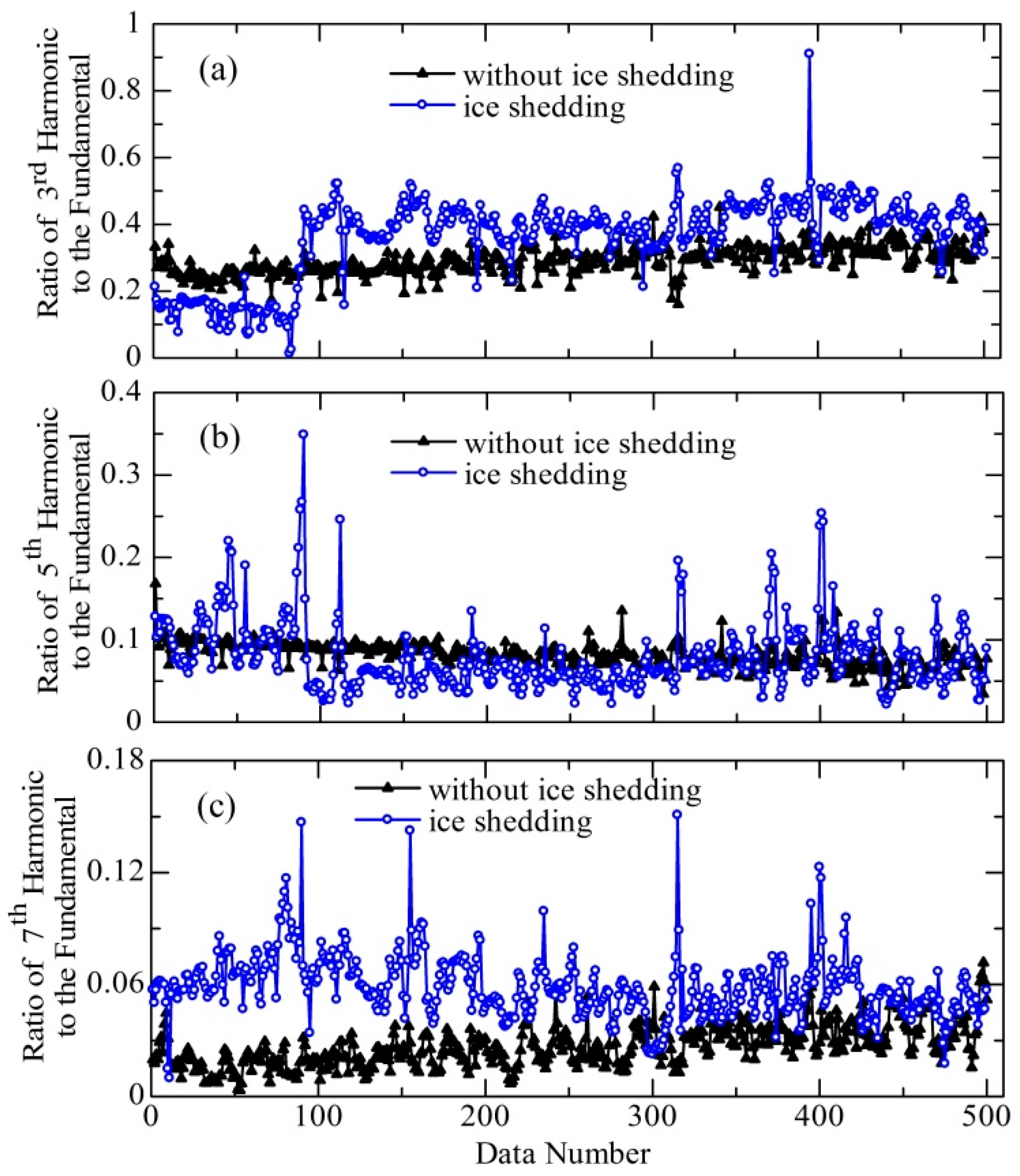
4.2. Ratio of Harmonics to the Fundamental Component

The ratio of harmonic components to the fundamental component can be attributed to the quantitative evaluation of the distortion level in the LC waveform, which responds to discharge behaviors related to a moderately high 3rd harmonic and successively smaller 5th and 7th harmonics [33,34]. Figure 6 presents the ratio of different harmonic components to the fundamental component of LC during the flashover process on the ice-covered insulator with and without ice shedding.
Under the without-ice shedding condition, all the ratios show a relatively stable variation during the flashover process, where the ratios of the 3rd and 7th harmonics to the fundamental component show an increasing tendency with the development of the flashover process. However, the ratio of the 5th harmonic to the fundamental component shows a slightly decreasing tendency. Such variation confirms that the flashover of an ice-covered outdoor insulator without ice shedding is a determined process induced by the initiation and formation of discharge arcs at the shortest air gaps and the discharge propagation along the ice layer due to ice melting. The obvious difference for the ice shedding condition is that all the ratios show a significant fluctuation during the flashover process, and that their varying tendencies cannot be clearly determined as those without ice shedding. This varying trend is related to the notable change of icing states of the ice-covered insulator caused by ice shedding. The appearance of the non-iced shed surface is associated with the random occurrence of discharge arcs in the ice-free regions and the slowing down of the ice layer melting for the propagation of discharge arcs. Therefore, the ratios of harmonics to the fundamental component are well in accordance with discharge behaviors and characteristics observed during the flashover process, which can be used as a tool for understanding and monitoring the impact of the icing state on the ice-covered outdoor insulators.

5. Conclusions

By analyzing the minimum flashover voltage (VMF) and time-frequency characteristics of the leakage current (LC) on an ice-covered suspension insulator string with and without the occurrence of ice shedding, the effects of ice shedding on discharge propagating characteristics of ice-covered outdoor insulators during the AC flashover process were investigated. The main conclusions are as follows.
(1)
Ice shedding restricts the extension of discharge arcs to the critical length for flashover, leading to VMF enhancement of about 17% from conditions of without ice shedding (VMF = 84 kVrms) to the occurrence of ice shedding (VMF = 98 kVrms).
(2)
Compared with a relatively easy initiation and stable occurrence of discharge arcs in shortest air gap on an ice-covered insulator without ice shedding, ice shedding restrains the initiation and formation of discharge arcs across ice-free regions. These arcs are characterized by an unstable propagating path, indeterminate arc shape and longer arc column.
(3)
The temporal variation of LC low-frequency components (the fundamental, 3rd, 5th and 7th harmonics) is well related to surface performance of an ice-covered outdoor insulator during AC flashover process, where the fundamental component indicates the melting process of the ice layer and the harmonic components accord with the discharge behaviors across ice-free areas.
(4)
Although VMF under ice shedding is higher than that without ice shedding, the fundamental component, 3rd, 5th and 7th harmonics under ice shedding overall show lower values and bigger fluctuation trends with the development of the flashover process.
(5)
The ratios of 3rd, 5th and 7th harmonics to the fundamental component are well in accordance with discharge characteristics of ice-covered insulators, where a relatively stable varying tendency can be determined for the without-ice shedding condition, but a significant fluctuation and indeterminate tendency for the ice shedding condition.

Author Contributions

X.L. and M.Z. conceived and designed the experiments; X.L. performed the experiments; X.L., Y.L., G.W. and L.J. analyzed the data; L.J. contributed analysis tools; X.L. wrote the paper.

Funding

This research received no extenal funding.

Conflicts of Interest

The authors declare no conflict of interest.

References

  1. Lu, J.Z.; Xie, P.K.; Jiang, Z.L.; Fang, Z.; Wu, W. Voltage distribution and flashover performance of 220 kV composite insulators under different icing conditions. Energies 2018, 11, 632. [Google Scholar] [CrossRef]
  2. Shu, L.C.; Wang, S.J.; Jiang, X.L.; Hu, Q.; Yang, X.Y.; Yang, S.; Chen, J. Effect of grading ring on ice characteristics and flashover performance of 220 kV composite insulators with different shed configurations. IEEE Trans. Dielectr. Electrl. Insul. 2015, 22, 951–960. [Google Scholar] [CrossRef]
  3. Hao, Y.P.; Wei, J.; Jiang, X.L.; Yang, L.; Li, L.C.; Wang, J.K.; Li, H.; Li, R.H. Icing condition assessment of in-service glass insulators based on graphical shed spacing and graphical shed overhang. Energies 2018, 11, 318. [Google Scholar] [CrossRef]
  4. Liu, Y.; Farzaneh, M.; Du, B.X. Investigation on shed icicle characteristics and induced surface discharges along a suspension insulator string during ice accretion. IET Gener. Transm. Distrib. 2017, 11, 1265–1269. [Google Scholar] [CrossRef]
  5. Deng, Y.; Jia, Z.D.; Jiang, H.; Guan, Z.C.; Zhou, J. Analysis of icicle growth process of composite insulator under energized condition and its impact factors. IEEE Trans. Dielectr. Electr. Insul. 2015, 22, 1613–1622. [Google Scholar] [CrossRef]
  6. Liu, Y.; Du, B.X.; Farzaneh, M. Self-Normalizing multivariate analysis of polymer insulator leakage current under severe fog conditions. IEEE Trans. Power Deliv. 2017, 32, 1279–1286. [Google Scholar] [CrossRef]
  7. Hara, M.; Phan, C.L. A Study of leakage current of HV insulators under glaze and rime. Can. Electr. Eng. J. 1978, 3, 15–22. [Google Scholar] [CrossRef]
  8. Jiang, X.L.; Wang, Q.L.; Zhang, Z.J.; Hu, J.L.; Hu, Q.; Zhu, C.Z. Ion migration in the process of water freezing under alternating electric field and its impact on insulator flashover. Energies 2017, 10, 61. [Google Scholar] [CrossRef]
  9. Farokhi, S.; Farzaneh, M.; Fofana, I. Experimental investigation of the process of arc propagation over an ice surface. IEEE Trans. Dielectr. Electr. Insul. 2010, 17, 458–464. [Google Scholar] [CrossRef]
  10. Fofana, I.; Farzaneh, M.; Hemmatjou, H.; Volat, C. Study of discharge in air from the tip of an icicle. IEEE Trans. Dielectr. Electr. Insul. 2008, 15, 730–740. [Google Scholar] [CrossRef]
  11. Arshad, M.; Nekahi, A.; McMeekin, S.G.; Farzaneh, M. Flashover characteristics of silicone rubber sheets under various environmental conditions. Energies 2016, 9, 683. [Google Scholar] [CrossRef]
  12. Jiang, X.L.; Dong, B.B.; Zhang, Z.J.; Yin, F.H.; Shu, L.C. Effect of shed configuration on DC flashover performance of ice-covered 110 kV composite insulators. IEEE Trans. Dielectr. Electr. Insul. 2013, 20, 699–705. [Google Scholar] [CrossRef]
  13. Hu, J.L.; Jiang, X.L.; Yin, F.H.; Zhang, Z.J. DC flashover performance of ice-covered composite insulators with parallel air gaps. Energies 2015, 8, 4983–4999. [Google Scholar] [CrossRef]
  14. Farzaneh, M.; Kiernicki, J. Flashover performance of IEEE standard insulators under ice conditions. IEEE Trans. Power Deliv. 1997, 12, 1602–1613. [Google Scholar] [CrossRef]
  15. Nekahi, A.; Farokhi, S.; Farzaneh, M.; Stewart, B.G. Arc energy and temperature during its propagation over ice-covered surfaces. IEEE Trans. Plasma Sci. 2014, 42, 114–119. [Google Scholar] [CrossRef]
  16. Farzaneh, M.; Zhang, J. A multi-arc model for predicting AC critical flashover voltage of ice-covered insulators. IEEE Trans. Dielectr. Electr. Insul. 2007, 14, 1401–1409. [Google Scholar] [CrossRef]
  17. Farzaneh, M.; Zhang, J.; Chaarani, R.; Fikke, S.M. Critical conditions of AC arc propagation on ice surfaces. In Proceedings of the IEEE International Symposium on Electrical Insulation, Anaheim, CA, USA, 2–5 April 2000. [Google Scholar]
  18. Farzaneh, M.; Volat, C.; Zhang, J. Role of air gaps on AC withstand voltage of an ice-covered insulator string. IEEE Trans. Dielectr. Electr. Insul. 2007, 13, 1350–1357. [Google Scholar] [CrossRef]
  19. Volat, C.; Farzaneh, M. Three-dimensional modeling of potential and electric-field distributions along an EHV ceramic post insulator covered with ice—Part I: Simulations of a melting period. IEEE Trans. Power Deliv. 2005, 20, 2006–2013. [Google Scholar] [CrossRef]
  20. Volat, C.; Farzaneh, M. Three-dimensional modeling of potential and electric-field distributions along an EHV ceramic post insulator covered with ice—Part II: Effect of air gaps and partial arcs. IEEE Trans. Power Deliv. 2005, 20, 2014–2021. [Google Scholar] [CrossRef]
  21. Wang, Y.X.; Jiang, X.L.; Fan, S.H.; Meng, Z.G. Asynchronism of ice shedding from the de-iced conductor based on heat transfer. IET Sci. Meas. Technol. 2016, 10, 389–395. [Google Scholar]
  22. Jiang, X.L.; Fan, S.H.; Zhang, Z.J.; Sun, C.X.; Shu, L.C. Simulation and experimental investigation of DC ice-melting process on an iced conductor. IEEE Trans. Power Deliv. 2010, 25, 919–929. [Google Scholar] [CrossRef]
  23. Farzaneh, M.; Zhang, J.; Chen, X. Modeling of the AC arc discharge on ice surfaces. IEEE Trans. Power Deliv. 1997, 12, 325–338. [Google Scholar] [CrossRef]
  24. Volat, C.; Meghnefi, F.; Farzaneh, M.; Ezzaidi, H. Monitoring leakage current of ice-covered station post insulator using artificial neural networks. IEEE Trans. Dielectr. Electr. Insul. 2010, 17, 443–450. [Google Scholar] [CrossRef]
  25. El-Hag, A.H.; Jayaram, S.H.; Cherney, E.A. Fundamental and low frequency harmonic components of leakage current as a diagnostic tool to study aging of RTV and HTV silicone rubber in salt-fog. IEEE Trans. Dielectr. Electr. Insul. 2003, 10, 128–136. [Google Scholar] [CrossRef]
  26. Suda, T. Frequency characteristics of leakage current waveforms of a string of suspension insulators. IEEE Trans. Power Deliv. 2005, 20, 481–487. [Google Scholar]
  27. Jiang, X.L.; Shi, Y.; Sun, C.X.; Zhang, Z.J. Evaluating the safety condition of porcelain insulators by the time and frequency characteristics of LC based on artificial pollution tests. IEEE Trans. Dielectr. Electr. Insul. 2010, 17, 481–489. [Google Scholar] [CrossRef]
  28. Chen, W.G.; Wang, W.P.; Xia, Q.; Luo, B.; Li, L.C. Insulator contamination forecasting based on fractal analysis of leakage current. Energies 2012, 5, 2594–2607. [Google Scholar] [CrossRef]
  29. Liu, Y.; Farzaneh, M.; Du, B.X. Using chaotic features of leakage current for monitoring dynamic behavior of surface discharges on an ice-covered insulator. IEEE Trans. Dielectr. Electr. Insul. 2017, 24, 2607–2615. [Google Scholar] [CrossRef]
  30. Kordkheili, H.H.; Abravesh, H.; Tabasi, M.; Dakhem, M.; Abravesh, M.M. Determining the probability of flashover occurrence in composite insulators by using leakage current harmonic components. IEEE Trans. Dielectr. Electr. Insul. 2010, 17, 502–512. [Google Scholar] [CrossRef]
  31. Tavares, M.; Talaisys, J.; Camara, A. Voltage harmonic content of long artificially generated electrical arc in out-door experiment at 500kV towers. IEEE Trans. Dielectr. Electr. Insul. 2014, 21, 1005–1014. [Google Scholar] [CrossRef]
  32. Liu, Y.; Farzaneh, M.; Du, B.X. Nonlinear characteristics of leakage current for flashover monitoring of ice-covered suspension insulators. IEEE Trans. Dielectr. Electr. Insul. 2016, 23, 1242–1250. [Google Scholar] [CrossRef]
  33. Bashir, N.; Ahmad, H. Odd harmonics and third to fifth harmonic ratios of leakage currents as diagnostic tools to study the ageing of glass insulators. IEEE Trans. Dielectr. Electr. Insul. 2010, 17, 819–832. [Google Scholar] [CrossRef]
  34. Pylarinos, D.; Theofilatos, K.; Siderakis, K.; Thalassinakis, E.; Vitellas, I.; Alexandridis, A.T.; Pyrgioti, E. Investigation and classification of field leakage current waveforms. IEEE Trans. Dielectr. Electrl. Insul. 2012, 19, 2111–2118. [Google Scholar] [CrossRef]
Figure 1. Schematic diagram of experimental setup.
Energies 11 02440 g001
Figure 2. Surface condition of ice-covered outdoor insulators: (a) occurrence of ice shedding; (b) without the ice shedding.
Energies 11 02440 g002
Figure 3. Minimum flashover voltage (VMF) of ice-covered insulators with and without the occurrence of ice shedding.
Energies 11 02440 g003
Figure 4. Flashover process of ice-covered insulators with and without ice shedding: (a) The discharge phenomena on the insulator without ice shedding; (b) the discharge pehnomena on the insulator with the occurrence of ice shedding.
Energies 11 02440 g004
Figure 5. Temporal variation of different LC components during the flashover process of ice-covered insulators with and without ice shedding: (a) fundamental component; (b) 3rd harmonics; (c) 5th harmonics; (d) 7th harmonics.
Energies 11 02440 g005
Figure 6. Ratio of different harmonics to the fundamental component during the flashover process of ice-covered insulators with and without ice shedding: (a) ratio of the 3rd harmonic to the fundamental; (b) ratio of the 5th harmonic to the fundamental; (c) ratio of the 7th harmonic to the fundamental.
Energies 11 02440 g006

