Abstract
With high penetration of renewable energy, DC distributed power systems (DDPSs) need to improve the inertia response and damping capacity of the power grid. The effects of main circuit parameters and control factors on the inertia, damping and synchronization of the DDPS were studied in this paper. Firstly, the dynamic model of DDPSs based on frequency droop control is established in the DC voltage control (DVC) timescale. Then, a static synchronous generator (SSG) model is used to analyze the parameters that affect the inertial level, damping effect and synchronization capability of the DDPS. The analysis results show that an optimal design of the frequency droop coefficient and proportional integral (PI) parameters of the DC bus voltage control loop can equivalently change the characteristics of inertia and damping when the frequency droop control strategy is applied to the DC/DC converter and the DC bus voltage control strategy is used in the grid-tied inverter. Simulation results verify the correctness of the conclusions. This paper helps to design an effective control strategy for DDPSs to enhance the inertial level and damping effect of the power grid and to improve the stable operation capability of renewable energy systems.
1. Introduction
In recent years, with the rapid development of power electronics, the proportion of power electronic equipment in the power grid has increased dramatically, and the effective control of electrical energy has become increasingly inseparable from the converter operation. Meanwhile, the proportion of the traditional rotary synchronous generator (RSG) has reduced in the power system with high renewable energy integration [1,2,3,4]. Renewable energy has the characteristics of intermittence and randomness, decreasing the stability margin of the power system. Therefore, the renewable energy generation system needs a friendly interaction between the grid-tied inverter and power grid to improve grid stability [5,6,7,8]. Then, DC distributed power systems (DDPSs) were introduced into the power grid to improve the inertial level and the damping effect of the power grid with renewable energy. Nowadays, the main control strategies of DDPSs are direct power control, frequency droop control and virtual synchronous generator (VSG) control.
Direct power control provides desired power based on the needs of the power system, and the desired power instructions are issued by the scheduling system [9]. However, direct power control cannot directly respond to the power grid frequency or improve grid frequency stability. The frequency droop control of DDPSs simulates the primary frequency modulation and quickly responds to the grid frequency variation. Frequency droop control is independent of the communication system and has high reliability and flexibility. At the same time, it is widely used in the grid-tied inverter systems [10,11,12]. Based on grid-tied inverter control and energy scheduling algorithms, VSG allows the DDPS to simulate the large inertia and strong damping characteristics of RSG [13,14,15]. Nevertheless, the VSG control also requires the frequency droop control loop for grid frequency response [16].
To investigate the concerned inertia and damping characteristics, this paper focuses on the DVC timescale dynamics [17], which corresponds to the electromechanical timescale dynamics in RSG [18]. In the DVC timescale, the frequency droop control is equal to the VSG control [19]. However, D’Arco et al. [19] did not analyze the influential parameters and the characteristic laws of inertia, damping and synchronization. As a result, engineers still cannot fully utilize the frequency droop control to improve the power grid stability. In [20], the static synchronous generator (SSG) model was proposed to effectively analyze the inertia and damping characteristics of the grid-tied inverter system based the double closed-loop control. Until now, based on the SSG model, the effect of the phase-locked loop on the dynamic characteristics of the inverter system was investigated [21,22]. Meanwhile, a novel inertia control method for the grid-tied inverter system has been put forward [23]. Therefore, the SSG model is a prospective and effective method to analyze the inertia and damping characteristics of DDPSs, while no work in this prospective direction has been done in other papers so far. Therefore, this paper is aimed at analyzing the influencing factors of the DDPS by the SSG model to provide a practical reference for optimal design.
This paper is organized as follows. This paper firstly introduces the DDPS, and the basic control principles of the DC/DC converter and the grid-tied inverter are analyzed and modeled in Section 2. In Section 3, the dynamics model of the DDPS based on the SSG model is established in the DVC timescale, which is simplified as a typical second order swing equation to analyze the inertia, damping and synchronization of the DDPS. Then, the effects of the main circuit parameters and key control factors on the inertia, damping and synchronization of the DDPS are studied. Finally, in Section 4, the simulation results show that DDPSs based on frequency droop control have the typical dynamic characteristics such as inertia, damping and synchronization, which can be well designed and fully utilized to enhance the power grid stability.
2. DC Distributed Power Systems Based on Frequency Droop Control
The schematic view of DDPSs based on frequency droop control is shown in Figure 1, including the DC distributed energy sources, the DC/DC converter based on the frequency droop control and the grid-tied inverter based on the DC bus voltage control. The DC/DC converter is equivalent to the prime mover in the conventional generator, and the grid-tied inverter plays the role of RSG in the conventional generation system.
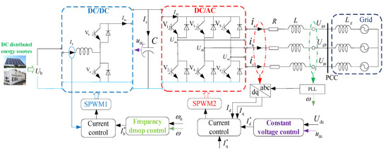
Figure 1.
DC distributed power systems (DDPSs) based on frequency droop control.
In Figure 1, Ugk (k = a, b, c) is the grid line-to-line voltage. Usk and ik are the voltage and current of the grid-tied inverter. Ub is the voltage of the DC distributed energy sources. R and L are the equivalent resistance and inductance, respectively. SPWM is a method of sinusoidal pulse width modulation. PLL indicates the phase-locked loop. In the following subsections, the basic control principles of the DC/DC converter and the grid-tied inverter are analyzed and modeled, serving as the bases for dynamic behavior inspection.
2.1. DC/DC Converter Control
From the perspective of the SSG model in [20], the DC distributed energy sources, the DC/DC converter and the grid-tied inverter correspond to the primary energy sources, the prime mover and the RSG, respectively. Moreover, the DC-side capacitor corresponds to the rotor of RSG. Therefore, the DDPS can be simplified (see Figure 2).
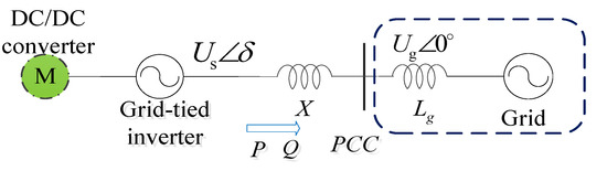
Figure 2.
Simplified circuit diagram.
δ is the phase angle difference between the output voltage of the DDPS and the grid voltage. The equivalent impedance of the DDPS and the line is X. PCC is the point of common coupling. This paper uses the grid voltage vector orientation for the d-axis reference, and the phasor diagram is shown in Figure 3.
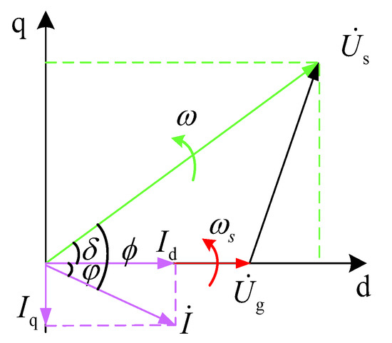
Figure 3.
Phasor diagram.
The voltage and current are transformed into the d-q frame, and the transformation matrix is adopted as:
The electromagnetic power and reactive power of the DDPS are expressed as:
According to Figure 2, Equations (2) and (3), we have:
According to Equations (4) and (5), the electromagnetic power Pe can be changed by adjusting δ, Us, Ug and X. The reactive power Q is mainly determined by Us. The power grid voltage Ug is generally a constant value. X is the structural parameter of the system and is not convenient to change. Thus, changing the electromagnetic power Pe mainly adjusts δ. Pe and Pin are approximately equal at steady state. Therefore, the frequency droop curve can be obtained as shown in Figure 4.
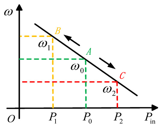
Figure 4.
The frequency droop curve.
According to Figure 4, it is indicated that:
where Dp is the frequency droop coefficient. P0 is the rated power of the DC/DC converter, and Pin is the actual power of the DC/DC converter.
Then, Equation (6) can be rewritten as:
If the energy of the DC distributed energy sources is stable and sufficient, the DC/DC converter can achieve a fast response of the grid frequency, referring to the primary frequency modulation process of the power system. Obviously, the frequency droop control of DDPSs essentially corresponds to the droop characteristics of the traditional power generation system (see Figure 5).
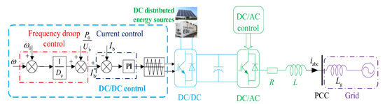
Figure 5.
Control block diagram of the DC/DC converter.
As shown in Figure 5, the bandwidth of the current loop is generally much larger than the bandwidth of the frequency droop loop. At the same time, the dynamic time of the inner loop is also much shorter than the outer loop. Therefore, the dynamic process of the inner loop is negligible in the DVC timescale. According to Figure 5 and the DVC timescale, we have:
2.2. Grid-Tied Inverter Control
The DC bus voltage closed-loop control is used in the DC/AC circuit of the DDPS to stabilize DC-side capacitor voltage (see Figure 6).
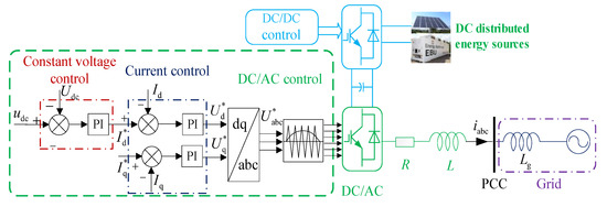
Figure 6.
Control block diagram of the grid-tied inverter.
As shown in Figure 6, the DC bus voltage control of the grid-tied inverter adopts proportional integral (PI) control, and a negative voltage feedback is added to the control strategy to achieve no-difference control. The DDPS mainly provides active power in this paper, so the q-axis current command can be set to zero. Hence, according to Figure 6, we have:
where Kp and Ki are the proportional gain and the integral gain of the DC bus voltage control, respectively.
3. Dynamic Analysis of the DC Distributed Power Systems
In this section, the dynamic characteristics of the DDPS will be analyzed, and the influential factors and laws will be summarized. The results are then utilized to analyze the inertia, damping and synchronous dynamic performance of the DDPS.
From Figure 1, we have:
The current of the DC-side capacitor is:
By substituting Equation (11) into Equation (10) and then dividing the equation by the base value of DC-side current IB, we have:
In Equation (12), the base value of current can be related to the base values of power and DC bus value as:
Hence, Equation (12) can be rewritten as:
where TJ is the equivalent inertia coefficient of SSG.
Furthermore, Equation (14) can be expressed as:
Because the change of udc in DC bus voltage control is small, it is assumed that udc* is one. Moreover, in the case of stability analysis, the conclusion will not be affected by this assumption. Therefore, linearizing Equation (15), the standard dynamic equation of DDPSs can be obtained as:
In Equation (16),
Based on the classical electric torque analysis in the power system, the dynamic model shown in Equation (16) can be rewritten as:
where TD and TS are the damping coefficient and the equivalent synchronization coefficient of SSG, respectively.
TJ, TD and TS are important physical concepts, which respectively represent the inertial level, damping effect and synchronization capability. In order to unify the analysis methods of the DDPS and SSG model, the relationship between ∆u and ∆ω will be found in the following.
According to Equations (9) and (19), we can deduce that:
The incremental relationship of variables is usually only considered for stability analysis. Therefore, Equation (20) is linearized as:
In Equation (21),
By manipulating Equation (21) and substituting ∆ω for s∆δ, we have:
According to Figure 1, the incremental power of the DC/DC converter is:
Substituting Equations (4), (23) and (24) into Equation (16), we give:
Simplifying Equation (25), the SSG equation of the DDPS can be obtained as:
According to Equation (26), the Phillips–Heffron model of DDPSs with frequency droop control can be obtained, and its structure is completely consistent with RSG (see Figure 7).
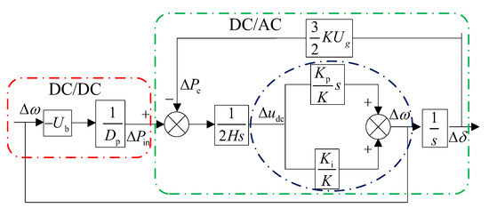
Figure 7.
The Phillips–Heffron model of the DC distributed power system (DDPS).
It can be seen that the operating mechanism of the DDPS in the DVC timescale is very similar to the traditional power generation systems on the electromechanical time scale. At the same time, all of them have the inertia, damping and synchronization characteristics. The TJ, TD and TS of the DDPS are:
It can be seen from Equation (27) that the inertial level, damping effect and synchronization capability of the DDPS are determined simultaneously by the structural parameters, control parameters and steady-state operating points. The structural parameters include the capacitance of the DC-side capacitor C and the equivalent impedance X; The frequency droop coefficient of the DC/DC converter and the PI parameters of the DC bus voltage control loop of the DC/AC converter are the control parameters; The operating points of steady state are comprised of the steady state power angle δ0, the capacitor rated voltage Udc, the inverter output voltage US, the voltage of the DC distributed energy sources Ub and the grid voltage Ug.
Therefore, the simplest way to control the inertia and damping characteristics of the system is obviously adjusting the control parameters of the DDPS. On the grounds of Equation (27) and its related analysis, the following main conclusions are obtained:
- (1)
- The inertial level can be adjusted by the proportional controller gain Kp and the frequency droop coefficient Dp. Meanwhile, adjusting the capacitance of the DC-side capacitor C, the voltage of the DC distributed energy sources Ub, the inverter output voltage US and the capacitor rated voltage Udc can also equivalently adjust the inertial level of the system. When C increases, the system increases the buffering effect against external disturbances and improves the inertia level of the system, which are consistent with the actual situation.
- (2)
- Changing the frequency droop coefficient Dp and the PI controllers of the DC bus voltage control loop can be equivalent to adjusting the damping effect of the system.
- (3)
- The synchronization capability can be changed by adjusting the integral controller gain Ki.
In summary, optimizing the frequency droop control loop and the DC bus voltage control loop can equivalently change the inertial and damping characteristics of the system. Besides, according to Equation (27), it is shown that the inertia factor of the DDPS also includes the components that are completely unrelated to the control parameters, and that part is only determined by the structural parameters and the steady-state operating points. The results show that the DDPS naturally has an inertial effect, which is opposed to the traditional idea of DDPSs having no inertia effect.
4. Simulation Verification
The simulation model was established in MATLAB/Simulink to demonstrate the effects of the DDPS parameters on the inertial level, damping effect and synchronization capability. The simulation circuit is shown in Figure 1, and the circuit parameters of the DDPS are shown in Table 1. A frequency disturbance occurs at the time of 0.03 s.

Table 1.
Main parameters of the DC distributed power systems (DDPSs).
4.1. Damping Characteristics Verification
On the basis of Equation (27), the damping characteristics are influenced by the frequency droop coefficient and the PI parameters of the DC bus voltage control loop. Dp demonstrates the dynamic behavior of udc (see Figure 8).
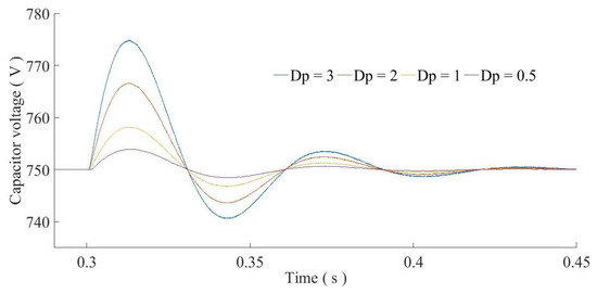
Figure 8.
Influence of Dp on the dynamic performance of the DDPS.
The simulation results show that with the increase of Dp, the oscillation amplitude of the capacitor voltage udc increases, and the oscillation attenuation becomes slower. At the same time, the inertia level of the system is inversely proportional to Dp. In summary, with the decrease of Dp, the inertial level and damping effect of the DDPS are enhanced, which is consistent with Equation (27). Adjusting Dp, Kp and Ki allows adjusting the damping characteristic equivalently.
Figure 9 shows that the damping effect of the DDPS is changed by Kp. The oscillation amplitude becomes smaller with the increase of Kp, obtaining a stronger damping effect. When Kp is one, the DDPS operates in a critical damping state and is characterized by small overshooting and fast dynamics. It is obvious that larger Kp has a better damping effect. However, a large Kp can cause DDPS instability, when the DDPS stability margin is small.
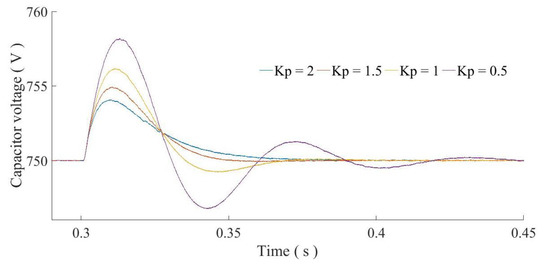
Figure 9.
Influence of Kp on the dynamic performance of the DDPS.
4.2. Inertial Characteristics’ Verification
According to Equation (27), the inertial coefficient of the DDPS is affected by the proportional controller gain Kp, the frequency droop coefficient Dp, the capacitance of the DC-side capacitor C and the capacitor rated voltage Udc. The ability of the DDPS to resist external interference is affected by the capacitance of the DC-side capacitor (see Figure 10).
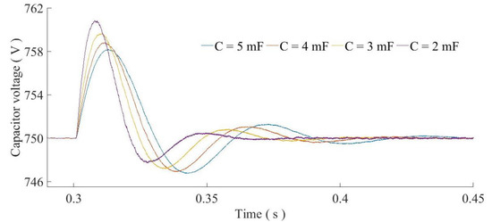
Figure 10.
Influence of C on dynamic performance of the DDPS.
With the increase of C, the oscillation amplitude of udc decreases, obtaining better resistance of the DDPS against external disturbances. The higher inertia level is conducive to maintaining the stability of the system, avoiding big fluctuation or, even worse, a fault in the external disturbances. This result is consistent with Equation (27). Besides, a larger C makes the DC-side capacitor voltage smoother.
The per-unit value is used in the case of different capacitor rated voltages Udc to better express the dynamic characteristics of the system (see Figure 11). The simulation results show that with the increase of Udc, the oscillation amplitude of udc decreases. At the same time, the ability of the DDPS to resist external disturbances becomes stronger. In summary, with the increase of Udc, the inertial level of the DDPS is enhanced, which is coherent with Equation (27).
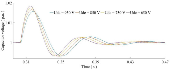
Figure 11.
Influence of Udc on the dynamic performance of the DDPS.
4.3. Synchronization Characteristics’ Verification
From Equation (27), it can be seen that adjusting the integral controller gain Ki and the grid voltage Ug allows equivalently adjusting the synchronization coefficient. When adjusting the integral controller gain Ki, the influence of the synchronization characteristics of the DDPS is as shown in Figure 12.
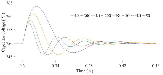
Figure 12.
Influence of Ki on dynamic performance of the DDPS.
As Ki increases, udc returns to a steady state faster. When the DDPS has a larger Ki, udc has a stronger adjustment ability and a stronger synchronization ability. The results are consistent with Equation (27) and Figure 11. Meanwhile, adjusting Ug and Ki allows adjusting the synchronization characteristic equivalently.
Figure 13 shows that with the increase of Ug, the time of the oscillation regression becomes shorter, and the synchronization ability is enhanced. It can be observed that as Ug increases, the synchronization capability becomes stronger, and the udc can quickly return to the steady-state value. Therefore, the results are consistent with Equation (27). The simulation results show that the inertial capability of udc is not affected by Ug. Therefore, Ug hardly affects the inertial effect of the DDPS, which is consistent with Equation (27).
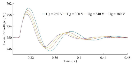
Figure 13.
Influence of Ug on the dynamic performance of the DDPS.
In the above cases, when the controller parameters are different, udc remains close to its rated value (750 V), although the dynamic characteristics are not the same. The deviations are less than 0.3%. The main reason is that the frequency droop loop and the DC bus voltage control loop provide a positive damping effect, inertial level and synchronization capability, and hence, the DDPS is small signal stable.
4.4. Stability Verification
The system stability of the DDPS is verified by an experimental platform for real-time simulation. The circuit parameters of the experimental platform for real-time simulation is shown in Table 2. The DDPS runs stably for a while, and then, a frequency disturbance occurs during stable operation.
Table 2.
Main parameters of real-time simulation.
Figure 14 shows the parameter variations of the DDPS when the frequency has a disturbance. The results show that udc can quickly stabilize at the set value after disturbance, and the active power output of the DDPS can also quickly reach a new steady state.
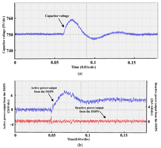
Figure 14.
The verification results: (a) the DC-side capacitor voltage; and (b) active and reactive power output from the DDPS.
5. Conclusions
Enhancing the inertial level, damping effect and synchronization capability of the DDPS are conducive to improving the frequency stability of the power grid. In this paper, the dynamic model of the DDPS based on the SSG model was established in the DVC timescale, analyzing the intrinsic mechanism, mainly affecting the parameters and influential laws of the inertial level and damping effect of the DDPS. The results show that the inertia, damping and synchronization characteristics of DDPSs with frequency droop control are determined by the structural parameters, control parameters and steady-state operating points. The main sources of the inertial level and damping effect of the DDPS are the frequency droop coefficient and PI parameters of the DC bus voltage control loop. Furthermore, the DC/DC converter using the frequency droop control intrinsically corresponds to the droop control characteristics of the prime mover. The simulation results show that the DDPS has the typical dynamic characteristics such as the inertia, damping and synchronization, which can be well designed and utilized to enhance the power grid stability.
Author Contributions
All the authors conceived of and designed the study. L.X. (Liancheng Xiu) and L.X. (Liansong Xiong) performed the simulation and wrote the manuscript with the guidance of P.Y. and Z.K.
Funding
The work was supported by the National Natural Science Foundation of China (Grant Nos. 51707091), the Scientific Research Foundation for the High-level Personnel of Nanjing Institute of Technology (Grant No. YKJ201613), the Open Research Fund of Jiangsu Collaborative Innovation Center for a Smart Distribution Network, Nanjing Institute of Technology (Grant No. XTCX201711) and the Operation Fund of Guangdong Key Laboratory of Clean Energy Technology (Grant No. 2014B030301022).
Conflicts of Interest
The authors declare no conflict of interest.
References
- Soder, L.; Hofmann, L.; Orths, A.; Holttinen, H.; Wan, Y.H.; Tuohy, A. Experience from wind integration in some high penetration areas. IEEE Trans. Energy Convers. 2007, 22, 4–12. [Google Scholar] [CrossRef]
- Kazemlou, S.; Mehraeen, S. Stability of multi-generator power system with penetration of renewable energy sources. In Proceedings of the 2012 IEEE Power and Energy Society General Meeting, San Diego, CA, USA, 22–26 July 2012; pp. 1–6. [Google Scholar]
- Doherty, R.; Mullane, A.; Nolan, G.; Burke, D.J.; Bryson, A.; O’Malley, M. An assessment of the impact of wind generation on system frequency control. IEEE Trans. Power Syst. 2010, 25, 452–460. [Google Scholar] [CrossRef]
- Li, Y.; Xu, Z.; Wong, K.P. Advanced control strategies of pmsg-based wind turbines for system inertia support. IEEE Trans. Power Syst. 2017, 32, 3027–3037. [Google Scholar] [CrossRef]
- Xiong, L.; Li, Y.; Zhu, Y.; Yang, P.; Xu, Z. Coordinated control schemes of super-capacitor and kinetic energy of dfig for system frequency support. Energies 2018, 11, 103. [Google Scholar] [CrossRef]
- Majumder, R. Some aspects of stability in microgrids. IEEE Trans. Power Syst. 2013, 28, 3243–3252. [Google Scholar] [CrossRef]
- Lee, D.J.; Wang, L. Small-signal stability analysis of an autonomous hybrid renewable energy power generation/energy storage system part i: Time-domain simulations. IEEE Trans. Energy Convers. 2008, 23, 311–320. [Google Scholar] [CrossRef]
- Guo, X.; Lu, Z.; Wang, B.; Sun, X.; Wang, L.; Guerrero, J.M. Dynamic phasors-based modeling and stability analysis of droop-controlled inverters for microgrid applications. IEEE Trans. Smart Grid 2014, 5, 2980–2987. [Google Scholar] [CrossRef]
- Zhi, D.; Xu, L. Direct power control of dfig with constant switching frequency and improved transient performance. IEEE Trans. Energy Convers. 2007, 22, 110–118. [Google Scholar] [CrossRef]
- Pogaku, N.; Prodanovic, M.; Green, T.C. Modeling, analysis and testing of autonomous operation of an inverter-based microgrid. IEEE Trans. Power Electron. 2007, 22, 613–625. [Google Scholar] [CrossRef]
- Zhong, Q.C.; Konstantopoulos, G.C. Current-limiting droop control of grid-connected inverters. IEEE Trans. Ind. Electron. 2016, 64, 5963–5973. [Google Scholar] [CrossRef]
- Yao, W.; Chen, M.; Matas, J.; Guerrero, J.M.; Qian, Z.M. Design and analysis of the droop control method for parallel inverters considering the impact of the complex impedance on the power sharing. IEEE Trans. Ind. Electron. 2011, 58, 576–588. [Google Scholar] [CrossRef]
- Shintai, T.; Miura, Y.; Ise, T. Oscillation damping of a distributed generator using a virtual synchronous generator. IEEE Trans. Power Deliv. 2014, 29, 668–676. [Google Scholar] [CrossRef]
- Alipoor, J.; Miura, Y.; Ise, T. Power system stabilization using virtual synchronous generator with alternating moment of inertia. IEEE J. Emerg. Sel. Top. Power Electron. 2015, 3, 451–458. [Google Scholar] [CrossRef]
- Bevrani, H.; Ise, T.; Miura, Y. Virtual synchronous generators: A survey and new perspectives. Int. J. Electr. Power Energy Syst. 2014, 54, 244–254. [Google Scholar] [CrossRef]
- Wu, H.; Ruan, X.; Yang, D.; Chen, X.; Zhao, W.; Lv, Z.; Zhong, Q.C. Small-signal modeling and parameters design for virtual synchronous generators. IEEE Trans. Ind. Electron. 2016, 63, 4292–4303. [Google Scholar] [CrossRef]
- Yuan, H.; Yuan, X.; Hu, J. Modeling of grid-connected vscs for power system small-signal stability analysis in dc-link voltage control timescale. IEEE Trans. Power Syst. 2017, 32, 3981–3991. [Google Scholar] [CrossRef]
- Hao, Y.; Hu, J.; Yuan, X. Modeling and large-signal stability of DFIG wind turbine in dc-voltage control time scale. In Proceedings of the 2016 IEEE Power and Energy Society General Meeting (PESGM), Boston, MA, USA, 17–21 July 2016. [Google Scholar]
- D’Arco, S.; Suul, J.A. Equivalence of virtual synchronous machines and frequency-droops for converter-based microgrids. IEEE Trans. Smart Grid 2014, 5, 394–395. [Google Scholar] [CrossRef]
- Xiong, L.; Zhuo, F.; Wang, F.; Liu, X.; Chen, Y.; Zhu, M.; Yi, H. Static synchronous generator model: A new perspective to investigate dynamic characteristics and stability issues of grid-tied pwm inverter. IEEE Trans. Power Electron. 2016, 31, 6264–6280. [Google Scholar] [CrossRef]
- Tan, S.; Lv, Q.; Geng, H.; Yang, G. An equivalent synchronous generator model for current-controlled voltage source converters considering the dynamic of phase-locked-loop. In Proceedings of the IECON 2016—42nd Annual Conference of the IEEE Industrial Electronics Society, Florence, Italy, 23–26 Octorber 2016; pp. 2235–2240. [Google Scholar]
- Tan, S.; Geng, H.; Yang, G. Phillips-Heffron model for current-controlled power electronic generation unit. J. Mod. Power Syst. Clean Energy 2018, 6, 582–594. [Google Scholar] [CrossRef]
- Wang, D.; Li, Y.; Xiong, L.; Lin, J. An inertia simulation method based on improved double-loop control for grid-connected inverters. In Proceedings of the 2017 IEEE 3rd International Future Energy Electronics Conference and ECCE Asia (IFEEC 2017—ECCE Asia), Kaohsiung, Taiwan, 3–7 June 2017. [Google Scholar]
© 2018 by the authors. Licensee MDPI, Basel, Switzerland. This article is an open access article distributed under the terms and conditions of the Creative Commons Attribution (CC BY) license (http://creativecommons.org/licenses/by/4.0/).