1. Introduction
Aiming for energy conservation, environment protection and continuous economic growth, many researchers are working on the improvement of energy efficiency [
1]. However, the progress of reducing the energy consumption is slow, even though China is subjected to increasing problems of energy shortage and environmental pollution [
2]. Dimitrovski et al. [
3] focused on the engine performance and emission analysis at various compression ratios and fuel blends. Optimum engine performance can be obtained at compression ratio of 18 for B20 fuel blend. Caratas et al. [
4] discussed the existing and foreseen barriers in the implementation and options to improve energy efficiency. It is advised that cost-effective energy strategies should include auditor managers considering the artificially low energy prices, the external costs of energy consumption or even the institutional factor. Irimescu et al. [
5] sought alternative fuels and selected gasoline–isobutanol blends to examine the emissions and performance of a four-stroke spark ignition engine. Superior efficiency of isobutanol combustion is an important gain while the undesirable increase of aldehyde is a major issue to deal with. Kerolli-Mustafa et al. [
6] gave a global assessment on biomass and biofuels sustainability by reviewing the relevant research. The overview shows that biomass and biofuel sustainability is influenced by several factors that affect food security as well as has socio-economic impacts. Brenna et al. [
7] proposed a possible way of modulating charge for a reliable systems integration between grid availability and the connected vehicles using batteries as electric energy storage system so that the electric grid can satisfy the electric need from home or work by treating to the connected vehicles as electric energy buffers.
Hybrid electric vehicles (HEVs), being one feasible solution for environmental protection [
8], have become major alternatives for replacing conventional vehicles powered by gasoline/diesel engines. The challenges of minimizing fuel consumption in the near future for HEVs are discussed [
9]. Nowadays, automotive manufacturers and researchers consider the powertrain architectures of power split electronic continuously variable transmission (power split e-CVT) as a mainstream of HEVs to develop due to its outstanding fuel economy, desirable driving performance [
10], and minimal requirement of battery capacity. A power split e-CVT system is typically composed of a power splitter that splits the power flow from engine into the mechanical and electric power flows. The former is directly transmitted through the drivetrain to offer major traction, while the latter is mostly circulated via two motor/generators [
11]. The purpose of this so-called electric circulation serves to fulfill the functionality of CVT as well as enhance the energy efficiency of the entire system.
The pioneer work of power split e-CVT was initially conducted by Gelb [
12]. Toyota Motor Co. developed a hybrid system called Toyota Hybrid System (THS) that is known as the first powertrain of power split e-CVT and succeeded in automotive market [
13,
14]. Nowadays, various systems of power split e-CVT have been proposed. Single-planetary and dual-planetary types are two architectures commonly used in automotive industry. For instance, some hybrid systems in market belonging to the former type are THS and Ford Hybrid System (FHS). The GM-Allison Advanced Hybrid System (AHS) may be attributed to the latter type. In recent years, the hybrid system of GM Volt described in the work of Miller et al. [
15] and the other one called single-mode full hybrid system proposed by Bing et al. [
16] are also classified as power split systems [
16]. Sheu [
17,
18] proposed a new power-split system of dual-planetary type. It can be operated in four operation modes: EV mode, engine and engine/charging mode, power mode 1, and power mode 2. System analysis with respect to speed and torque ratios at four modes is performed. Moreover, the effects of speed ratio of the planetary-gear transmission on mechanical efficiency are analyzed. Chung et al. [
19] introduced a new hybrid powertrain of power-split e-CVT, named the planetary gearset and dual one-way clutch hybrid electric system (PDOC). The results show that, compared with the conventional rubber-belt CVT system, PDOC can offer better driving performance and lower fuel consumption in cruise driving. A refined version documented in their subsequent work [
20] is called the planetary gearset and dual clutch (PDC) hybrid powertrain that consists of the engine-driven and power-split e-CVT operating modes, same as those of PDOC system. However, the PDC system possesses the capability of operating in two-motor electric vehicle mode because its motor and generator are connected as a torque coupler.
Two systematic classifications on the power split e-CVT powertrains specifically using planetary gearsets have been proposed by Miller [
21] and Ehsani et al. [
22]. Miller classified the powertrains into input split, output split, and compound split depending on how the power splitters are linked to the transmission ports. Ehsani et al. defined the power split e-CVT systems as a type of integrated speed-coupling and torque-coupling hybrid powertrain. However, these two classifications can only correspond the kinematic characteristics of the power-split powertrains, rather than the feature on energy management.
Some research works focus on developing a design methodology to search for possible combinations of multiple planetary gearsets for HEV applications including power split e-CVT. Zhang et al. [
23] first introduced a hybrid electric powertrain design methodology to analyze all possible kinematic combinations of system elements of the planetary gearsets under some predetermined numbers of components using graph theory and algebraic design techniques. Dagci et al. [
24] proposed a novel design methodology that utilizes a mode-based method to perform an exhaust search for suitable two-planetary-gearset HEV design of light-duty truck under no predetermined constraints. This trend shows that a proper classification of the planetary-gearset-based architectures of power split e-CVT is imperative to construct a more effective algorithm.
In this paper, a new classification of power split e-CVT concerning not only the effect of kinematics but also that of energy management is proposed so that the effects of electric circulation can be clearly revealed.
2. Classification of Power Split e-CVT
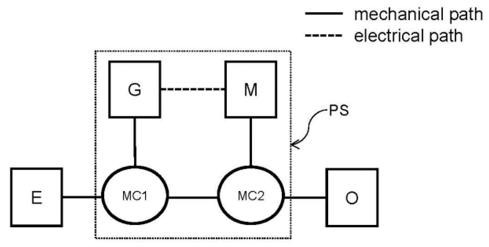
A typical architecture of power split e-CVT is illustrated by the diagram shown in
Figure 1. The engine (E), generator (G), motor (M), and output shaft (O) are mechanically linked to two mechanical coupling devices. One mechanical coupling device (MC1) is placed among the E, G, and the other mechanical coupling device (MC2), while the MC2 is mechanically connected with the M, MC1, and O. Here, a conventional gasoline or diesel engine is commonly used as E, serving as the sole power source to transmit the driving power to O. Moreover, the power split e-CVT system (PS), including the G, M, MC1, and MC2, acts as an electronic controlled variator to perform CVT function using electric circulation, that is, a certain amount of electrical energy generated from E is circulated through G and M and then merged with the mechanical energy from E at MC1. Thereby, by varying this electrical energy for a given load condition at output, the operating point of E can be shifted and allocated to an optimal point with respect to energy efficiency in favor of energy management.
Basically, there are two types of mechanical coupling according to the work of Ehsani et al. [
22] One is speed-coupling and the other is torque-coupling. The torque (
T) and rotational speed (
) relation of the former are expressed as below if the transmission loss is ignored:
where
and
are constants depending on the kinematic characteristics of coupling, and the subscripts 1, 2, and 3 represent the three connecting shafts of PS. As for the latter type, the torque and rotational speed relations with neglecting transmission loss are expressed in the following equations:
where
and
are constants depending on the kinematic characteristics of coupling.
Speed-coupling is also called differential or split. Generally, a HEV may be a type of pure torque-coupling, pure speed-coupling, or combined torque- and speed-coupling. However, a hybrid system to fulfill power split e-CVT operation requires at least one of the MC1 or MC2 to be speed-coupling. Thereby, the engine power flow can be split into a main mechanical path through the MC1 and MC2 giving the major traction power, and an electrical path via the G and M for electric circulation.
Even though the electric circulation encounters two losses of electric/mechanical energy conversion, this can be recompensed by the resulting efficiency improvement of the CVT operation. Thereby, a net gain on energy efficiency of the whole system can be achieved. Miller [
21] classified power split e-CVT systems into three basic types, i.e., input split, output split, and compound split. For an input split system, the MC1 is a power splitter, i.e., a speed-differential device, and the MC2 is a torque-coupling device. On the contrary, an output split system consists of a torque-coupling and a speed-coupling device for the MC1 and MC2, respectively. As for a compound split system, both MC1 and MC2 are of speed-coupling type.
The classifications described above are solely based on their kinematic characteristics. In this paper, an analytical approach is proposed to characterize these systems concerning not only the kinematic feature but also the effect of electric circulation on the energy management of a power split e-CVT system.
First, the operating point of E corresponding to a given output condition, i.e., a specific torque and rotational speed of O, and , is denoted as . This point can be shifted by varying the amount of circulating electric power and may reach an optimal point with maximum energy efficiency of the entire system PS. Understanding this trend is of importance to establish an effective energy management and control strategy.
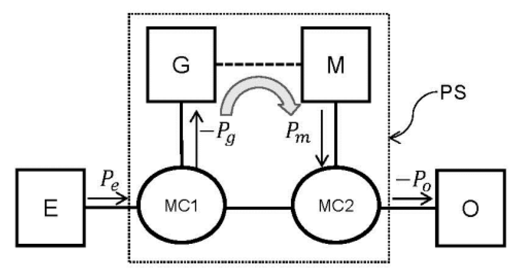
For this purpose, two relations of power are constructed, as indicated in
Figure 2. One is the relation between the power of the E,
, and that of the O,
, described as Equation (5).
where
is the total transmission efficiency of the PS including both mechanical and electrical losses along both the mechanical and electrical paths. The other is the relation between the power of the G,
, and that of the M,
, expressed as below:
where
is the transmission efficiency of the electric energy circulated from the G to the M. Furthermore, a parameter called the ratio of circulating power,
, is defined a ratio between
and
, i.e.
In this analysis, all the transmission losses of energy within PS are neglected, i.e., and , so that the analytic model can be simplified in a way of focusing on how the electric circulation can influence the operation of E. In addition, it should be noted that the sign of power flow is set positive if its direction is into the coupling devices, and vice versa. This simplified mathematic model is used to characterize how changing would affect under the operation of power split e-CVT.
For a given
and
, knowing that
and substituting it into Equation (5) yield
where
and
.
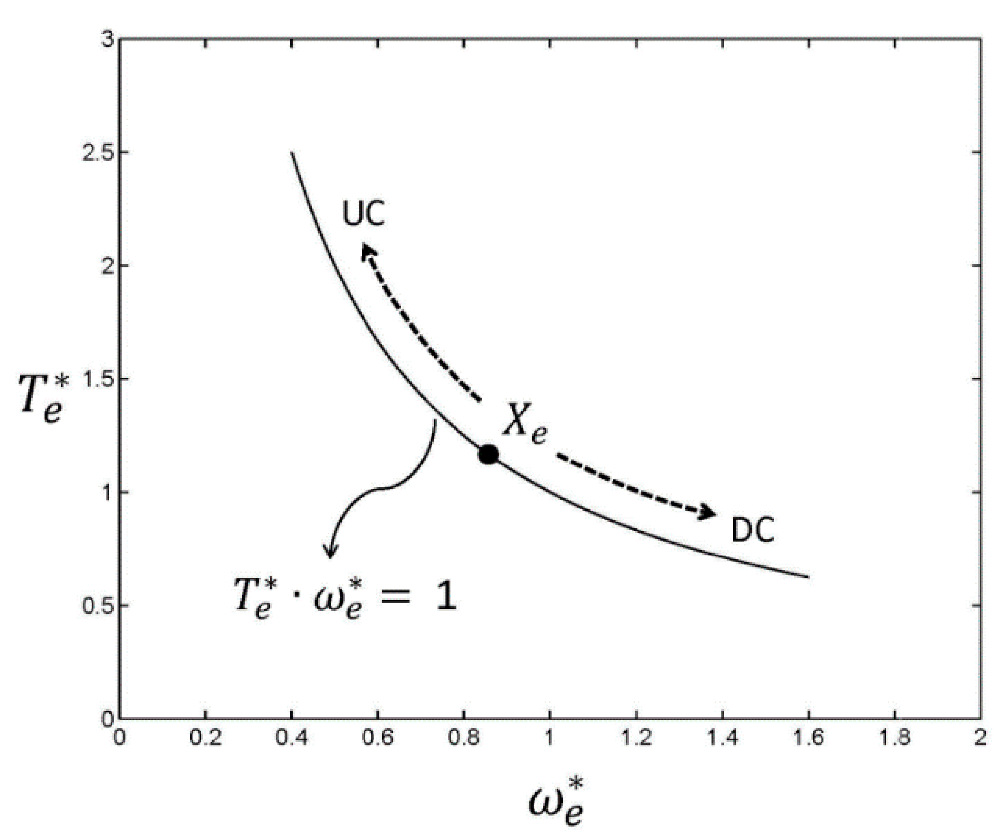
The curve of Equation (8) defined by
in terms of
and
, i.e.,
, is a parabola, as shown in
Figure 3. How this
moves along this curve as
varies may be regarded as a significant characteristic in view of energy management of power split e-CVT systems. The types of system may be classified as upward circulation (UC), downward circulation (DC), or neutral circulation (NC) if
moves in the direction marked UC, DC or does not move, respectively, as indicated in
Figure 3. This can be alternatively featured using the derivatives of
or
with respect to
obtained by differentiation of Equation (8) as denoted in Equation (9).
Now, type UC may correspond to the following condition:
Type DC is equivalent to the condition shown below:
Type NC is related to the condition stated below:
Considering the energy management of the power split e-CVT systems especially with common gasoline or diesel reciprocating engines, the
of type UC tends to move toward an operating zone with higher torque and lower rotational speed as
and
increase. This indicates that a hybrid system of type UC possesses desired potential of utilizing circulating power to further enhance the total energy efficiency especially when E is inevitably operated at relatively high rotational speed. On the contrary, the
of type UC tends to move toward an operating zone with lower torque and higher rotational speed as
and
increase. The advantage of this type is enhancing its CVT functionality especially when E is operated at a relatively low rotational speed. As for type NC, since the operation of E is uninfluenced by electric circulation, it will be excluded in the following discussion. Consequently, different strategies for energy management need to be adopted depending on which type the power split e-CVT system under development belongs to. In the following, two hybrid systems are selected as examples to demonstrate this analytical approach. One is THS (Toyota Hybrid System) that is widely known and successively implemented in passenger car. The other is PDC (Planetary Gearset and Dual Clutch) that is a novel hybrid proposed in the work of Chung and Hung [
20].
3. Analysis of Energy Management Characteristics of Electric Circulation on THS
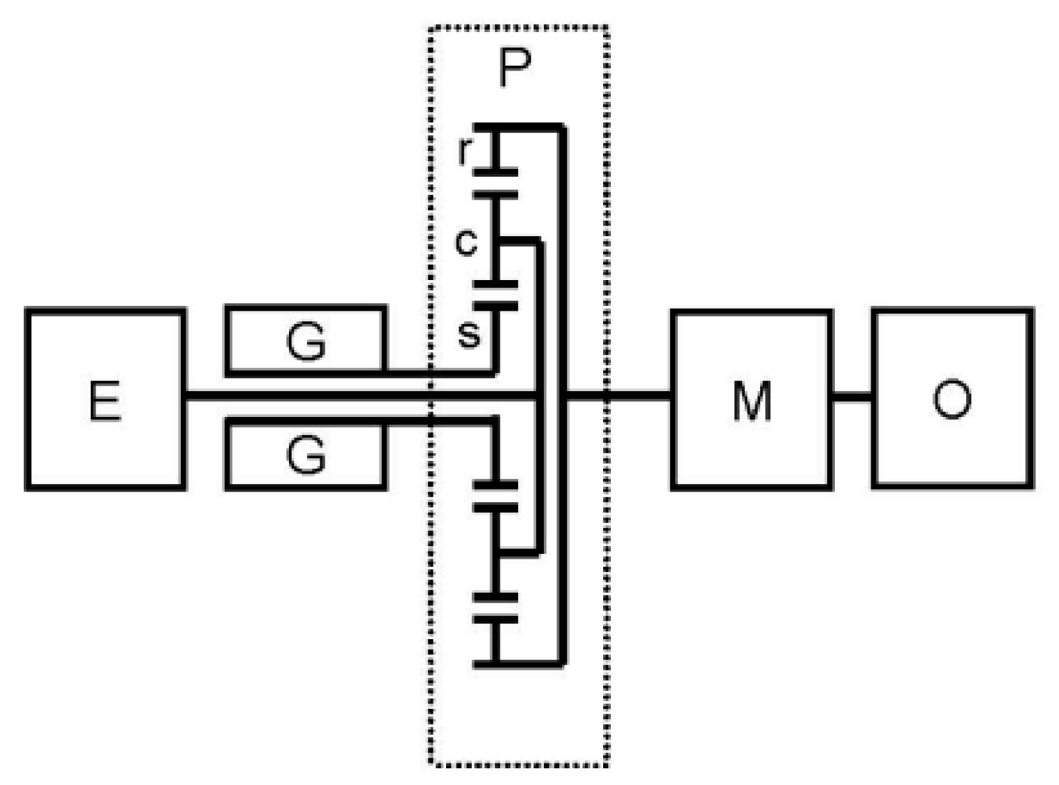
THS is a forerunner of the power split e-CVT system that can operate in various modes, such as single-motor electric vehicle, engine-assisted electric vehicle, engine-driven, power-split e-CVT, and boost modes. In hybrid drive, THS is mostly operated in power-split e-CVT mode, i.e., the electric circulation mode to minimize the charging/discharging load of energy storage system (i.e., battery). The schematic diagram for powertrain architecture of THS in the electric circulation mode is illustrated in
Figure 4. The planetary gearset (P) consists of a ring gear (r), a planetary carrier (c), and a sun gear (s). E and G are connected to the planetary carrier and the sun gear, respectively, while M directly coupled with the O is connected to the ring gear. The operation of power split e-CVT for THS is carried out by varying the rotational speed of G,
, as well as the amount of circulating electric power via G and M to modulate the rotational speed of E,
, for a given rotational speed of O,
.
The rotational speed and torque relations under power split e-CVT operation are expressed as follows:
where
is the basic ratio of P, i.e., the ratio between the teeth number of the ring gear and that of the sun gear. Part of the energy from E is converted into electric energy and circulated through G and M, and converted back to mechanical energy to fulfill the operation of power split e-CVT. This relation of electric circulation is expressed in Equation (6). Letting
and
, Equation (6) becomes
Since the G of THS serves to continuously modulate the speed ratio between E and O, Equations (13)–(15) are deliberately rearranged with the rotational speed of G being presented in terms of
defined by Equation (7). Letting
,
, and
, the following three equations can be obtained:
As a result, it can be found that both
and
are solely dependent on
, while
is a function of
, so that Equations (17) and (18) can be rewritten as
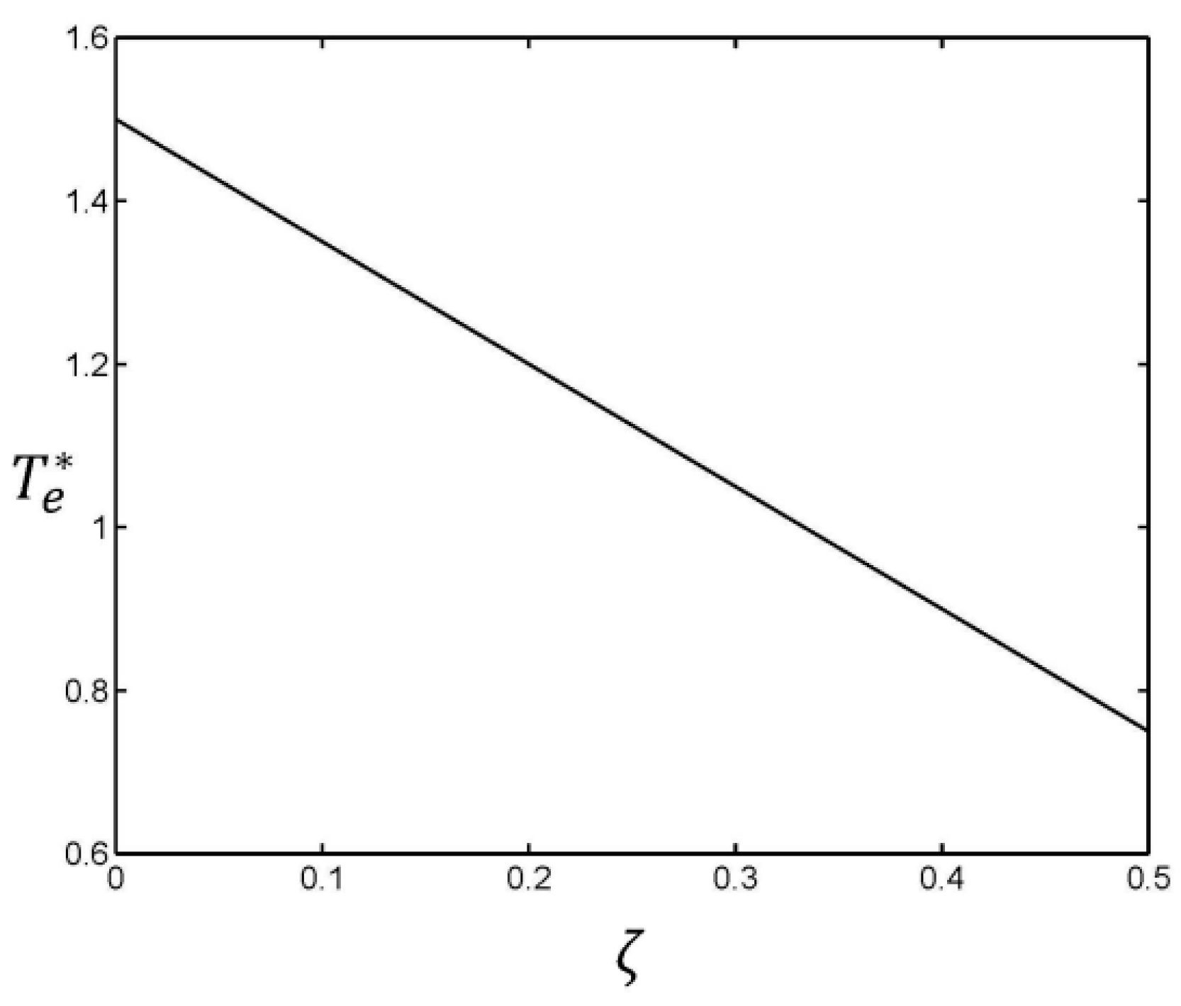
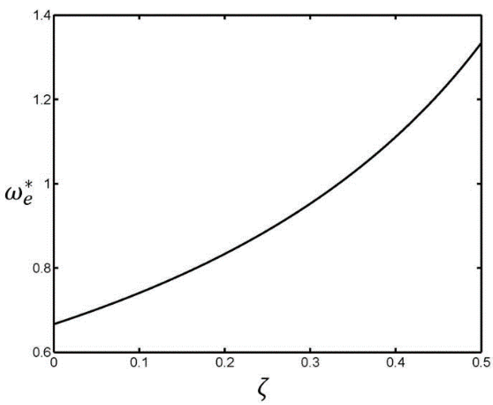
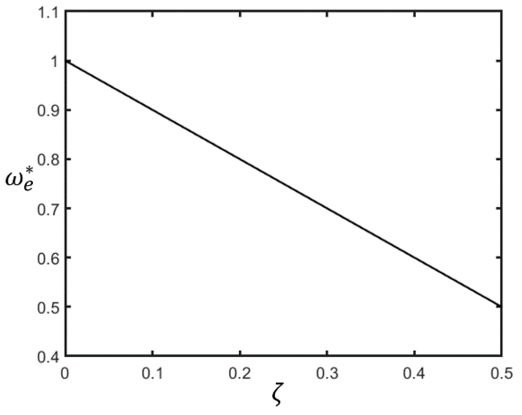
Now, letting the value of
be 2 and the parameter
vary in a range of 0–0.5, the trends of
and
in terms of
are evaluated and plotted in
Figure 5 and
Figure 6. The curves reveal that, as
increases,
decreases and
increases. Therefore, THS can be classified as type DC. Furthermore, this can be identified mathematically by taking a derivative of
(Equation (21)).
Since , this can be further confirmed according to the condition defined in Equation (11).
4. Analysis of Energy Management Characteristics of Electric Circulation on PDC
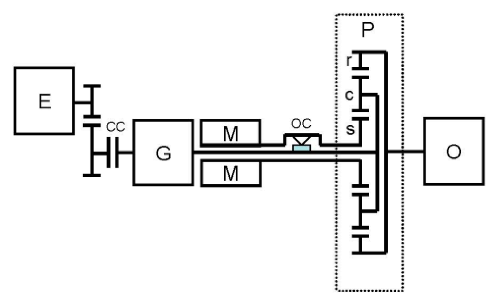
PDC is a novel powertrain of power split e-CVT that can be operated under various mode, such as the dual-motor electric vehicle (dual-motor EV), switching CVT (s-CVT), engine-driven, power-split e-CVT, and boost modes. Similar to THS, the electric circulation mode is the main operation mode in hybrid drive. The schematic diagram of PDC powertrain in the electric circulation mode is illustrated in
Figure 7. It consists of an engine (E), a generator (G), a driving motor (M), a set of planetary gearset (P), a controllable clutch (CC), and a one-way clutch (OC). The planetary carrier of P is connected to G through a reduction gear and CC. The sun gear of P is linked to M through OC. The ring gear of the P is directly coupled to O. Its power split e-CVT mode is achieved by varying the rotational speed of M in reverse direction to modulate the rotational speed of G and M with CC engaged under a specific rotational speed of O. The rotational speed and torque relations under the power split e-CVT mode are described in Equations (22)–(24).
where
is the reduction ratio between E and G. Similar to THS in regard to the power split e-CVT operation, Equation (15) is applied to PDC. However, unlike THS, the G of PDC rather than M is utilized to continuously vary the speed ratio between E and O by rotating in reverse. Thereby, Equations (22)–(24) are intentionally reconstructed so that the rotational speed of the M is related to
based on the definition in Equation (7). Again, letting
,
, and
, the following three equations can be obtained:
Combining Equations (25) and (27),
is expressed as
It reveals that both
and
are functions of
. Knowing that
from Equation (7), the range of
can be determined from Equation (25) and expressed below:
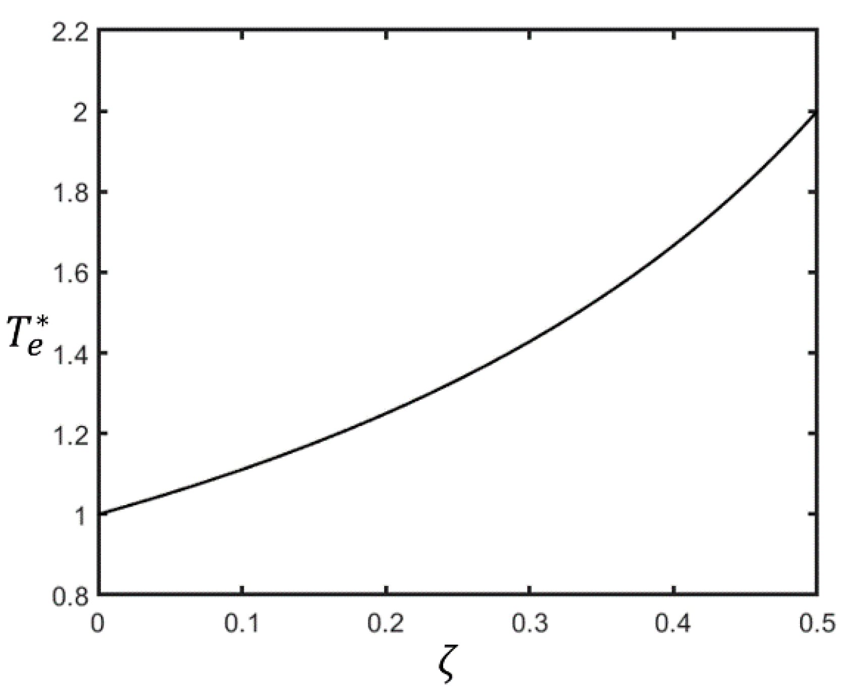
As a result, it is found that M is required to be rotated in reverse to fulfill the operation of electric circulation. Now, the values of
and
are assumed to be 2 and 1.5, respectively.
and
vs.
are plotted in
Figure 8 and
Figure 9. The results reveal that, as
increases,
increases and
decreases. Hence, PDC can be regarded as type UC. This can be further confirmed by taking a derivative of
expressed in Equation (30).
From Equation (30), can be clearly seen and thus PDC is a type of UC.
5. Characteristics of Energy Management Based on Simulation
In the previous work about assessment of the THS and PDC hybrid electric motorcycle, the energy efficiencies of applying electric circulation covering the whole operating region of the power split e-CVT and engine-driven mode have been simulated and compared. It should be noted that the engine-driven mode can be regarded as a special condition of the power split e-CVT mode with . The results can now be clearly understood based on the analytical approach in this paper.
The energy efficiency of the hybrid system is evaluated based on a so-called tank-to-wheel efficiency,
, that is expressed in the following equation:
where
is the driving power of the wheel and
is the power extracted from the fuel.
For both THS and PDC, the operating point of E for a given driving load condition at O can be shifted by varying the amount of circulating electric energy, i.e., the ratio of circulating power
. Each of these operating points of E has different value of tank-to-wheel efficiency
. Consequently, for each given driving load, i.e., a specific output condition of
and
, an optimal operating point with a maximum of
can be located.
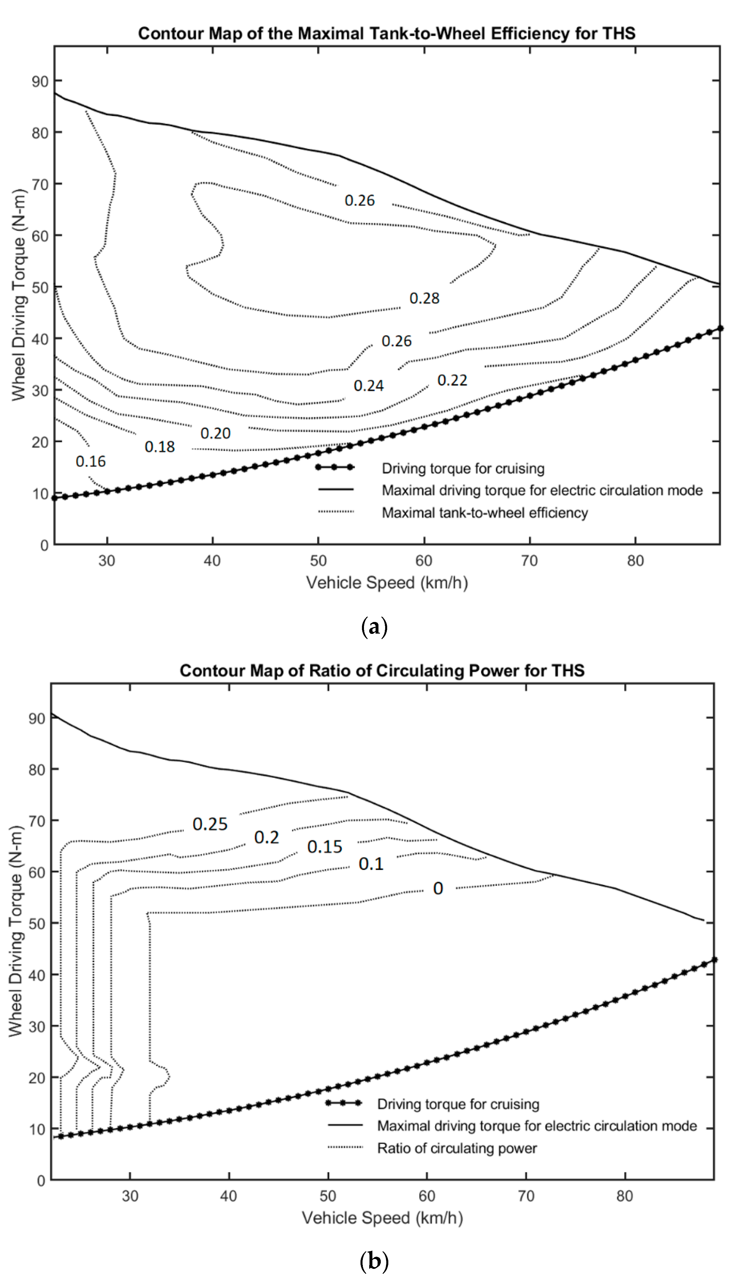
Figure 10a,b illustrates the contour maps of the maximal
and the corresponding
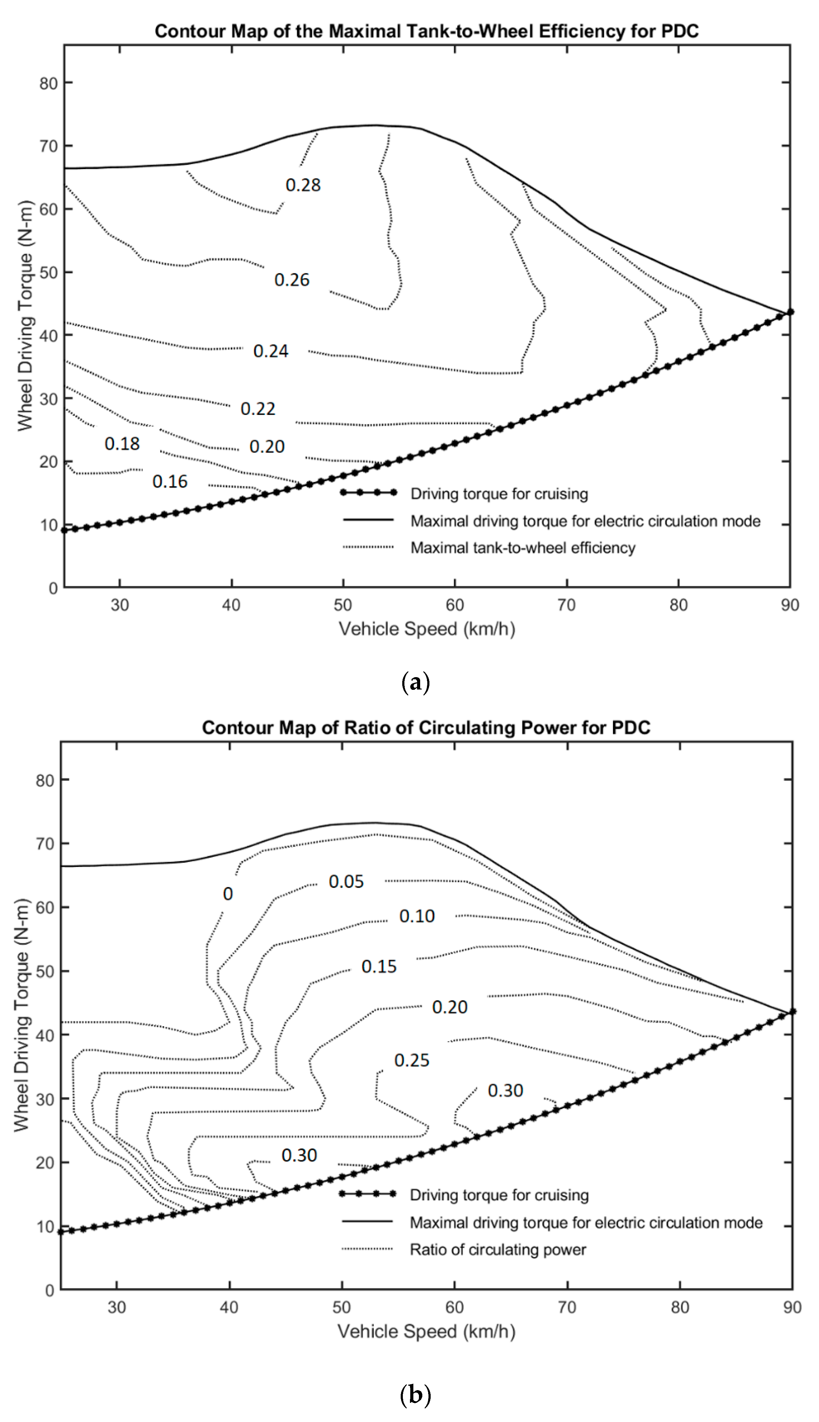
vs. vehicles speed for THS, respectively, while
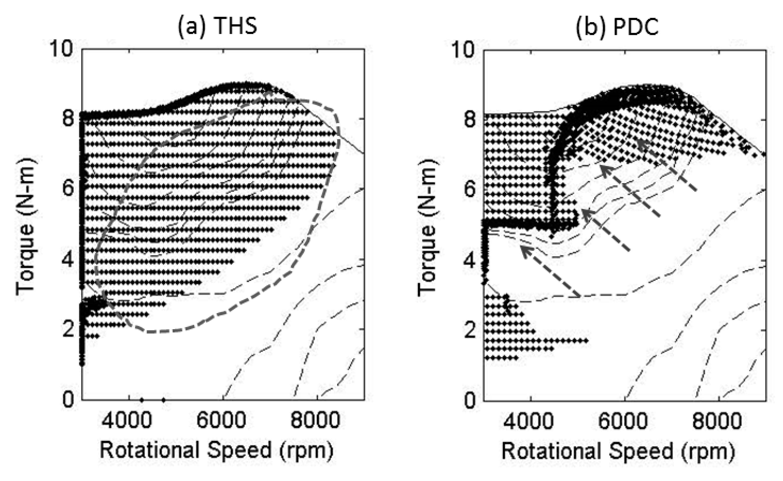
Figure 11a,b represents those for PDC. The related distributions of the optimal operating points of the E for THS and PDC are shown in
Figure 12a,b, respectively.
According to the analysis above, THS is a type of downward circulation (DC). Most
are inclined to shift downward as
increases so that the optimal operating points of E are located along the upper-left boundary or scattered downward over a low-efficiency zone, as indicated by a dotted circle in
Figure 12a. This indicates that DC hybrid systems such as THS generally gain benefits of energy efficiency from electric circulation especially when the engine operates at low speed and high load. Accordingly, the corresponding driving performance shown in
Figure 10a,b reveals that the optimal values of
increase toward the region of low vehicle velocity and high wheel driving torque. On the contrary, the optimal operations in the engine-driven mode, i.e.,
, dominate over a broad region of medium to high vehicle speed and light to medium wheel driving torque.
On the contrary, PDC is a type of upward circulation (UC) based on the analysis in this paper. This indicates that increasing
tends to shift
upward to a location of higher efficiency. As a result, higher values of
can be attained with the help of electric circulation, especially when the engine operates at high speed and low load. This can be further confirmed by looking at
Figure 12b with the arrow signs, showing that most of the optimal operating points are moved and concentrated on an upper area with high efficiency. The final optimal
is generally reached at a specific point where the increased losses mainly resulting from the energy conversions of both the G and M just outweigh the corresponding efficiency gain by shifting
. In view of
Figure 11a,b, it can be confirmed that the optimal values of
increase toward the location of high vehicle speed and low wheel driving torque. Clearly, PDC, being a type of UC, can take advantage of electric circulation at high driving speed and low driving load, especially at high cruising driving. Moreover, UC hybrid systems, being capable of lowering engine speed using electric circulation, are suitable for light-duty HEVs that are equipped with small-scale engines running at relatively high speed.
Now, it is found that DC and UC hybrid systems have different operating characteristics on applying electric circulation and their own advantages in different operating conditions. Therefore, a power split e-CVT powertrain possessing both DC and UC operating modes can be a favored solution for designing a hybrid vehicle with superior performance of energy efficiency covering an entire operating range.


