1. Introduction
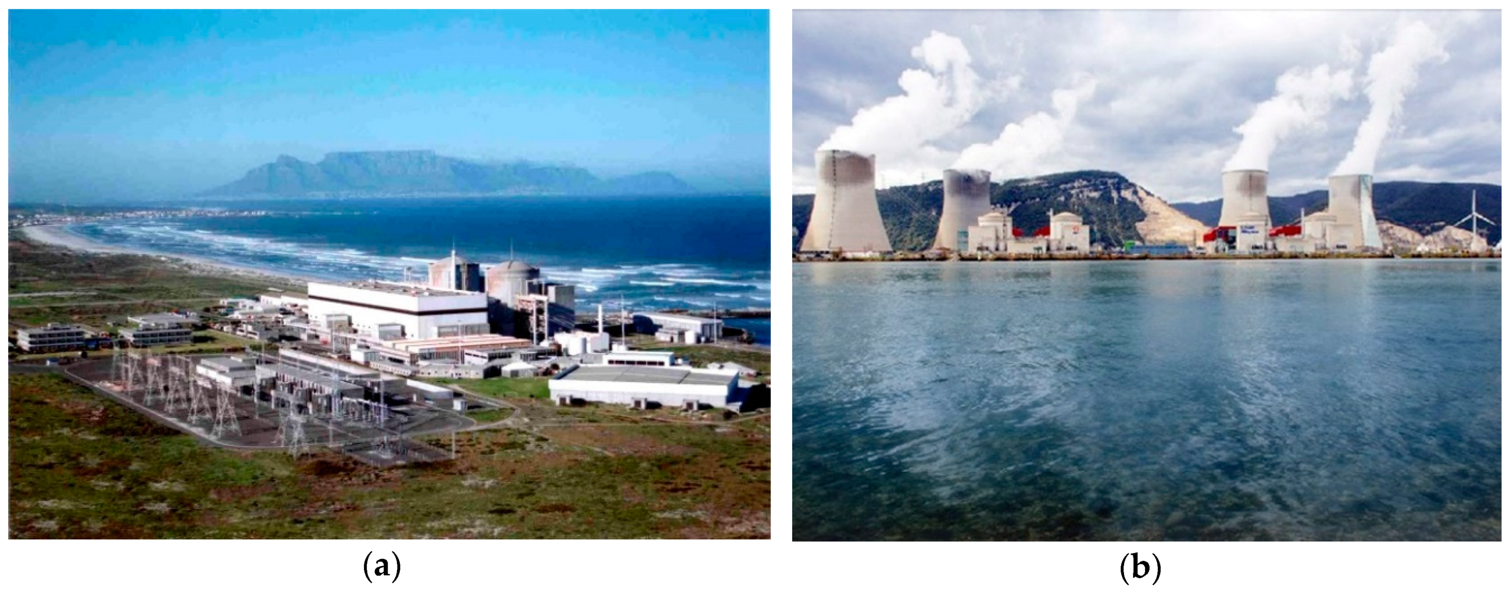
The use of seismic isolation has increased gradually around the world. Not a new technology for the nuclear industry, seismic isolation was used in two operating NPPs constructed in the 1970s. One is in Koeberg, South Africa, which is the first seismically isolated NPP in the world, and the other is in Cruas, France. The exterior photographs of the two plants are shown in
Figure 1, respectively [
1,
2]. In addition, it has been applied more recently to major research reactor facilities and emergency operations structures at nuclear power stations. The list of NPPs and nuclear reactor structures using seismic isolation is shown in
Table 1.
Although seismic isolation is a relatively mature technology, there remain a number of technical issues that have not been resolved to the level normally associated with the rigor and performance expectations of the nuclear power industry. In addition, nuclear power facilities raise a number of technical challenges not normally encountered in other applications due to the need for an explicit quantification of risk, the much higher performance criteria, the likely importance of soil-isolator-structure interaction, the regulatory need to consider three components of excitation and beyond-design-basis seismic events, the sheer size of the devices likely needed, and the safety importance of umbilicals. Thus, to support the application of seismic isolation to NPPs, additional research and development activities are needed.
To better understand potential difficulties in the application of seismic isolation to NPPs, a few in-depth interviews were conducted with manufacturers of seismic isolation devices and supplemental energy-dissipation devices as well as with experts responsible for monitoring the performance of seismic isolation systems in nuclear power plants. Less detailed interviews were conducted with representatives from several engineering firms who were experienced with seismic isolation in general and in the design of nuclear power facilities. The intent of these interviews was to identify any special problems that might be encountered in the planning, design, analysis, procurement, installation, operations, and maintenance stages of managing a seismically isolated structure. Several manufacturers were contacted and interviewed to provide information on how the overall process works from the initial conception through the active operation of the system. The manufacturers interviewed worked in the fields of Dynamic Isolation Systems (DIS), Earthquake Protection Systems (EPS), and Taylor Devices. In addition, the manager responsible for the maintenance of the isolation bearings in the NPP in Koeberg, South Africa provided significant insight into the serviceability of isolation systems in an NPP environment [
4].
In addition to the firsthand knowledge obtained from these interviews, this paper addresses several questions that repeatedly arose in discussions with design engineers. These related mainly to the durability of the isolation systems. Although a developing technology, the materials—such as elastomers and steel—that make up isolators have been used in various applications for over 100 years. To supplement these interviews, studies and research conducted in the area of radiation exposure and general durability are reviewed in this paper. This discussion should give insight and reassurance regarding the potential behavior of isolation systems over time.
2. Device-Related Issues
This section discusses issues related to the durability of isolators and the effects of radiation and other environmental exposure on isolators and fluid viscous dampers.
In general, before using a particular isolator or supplemental energy dissipation device in an NPP, it is expected that an extensive program of testing and analysis will be required to establish specific mechanical characteristics of the devices to be used. Thus, it is anticipated that knowledge of device properties will increase rapidly with time.
2.1. Durability of Isolation Systems
In terms of durability, the main focus is the effects of aging. Materials may have the tendency to change mechanical properties over time, which impacts their performance and the global performance of the isolated system. In the case of isolation, situations will arise where some systems will remain inactive for long periods of time while some systems will experience various levels of activity due to operating conditions (thermal or traffic loads or frequent low-level seismic activity). Regardless of this situation, the isolation system should perform well in the design-basis and the beyond-design-basis seismic excitations. Thus, characterization tests are often stipulated to simulate in-service wear on the isolators prior to tests replicating the effects of large seismic excitations.
With the initial use of seismic isolation in France, Electricité de France (EDF) began to compile findings of various studies on the elastomeric bearings used for bridges. From these studies, they saw that, after 20 years of use, there were no signs of serious problems with aging. However, in spite of the excellent consistency of properties over several decades, EDF and others have strongly recommended that the design of seismically isolated NPPs be done in such a way as to facilitate the replacement of isolators [
5]. Replacement might also be warranted if the seismic hazard at a plant changes significantly during its service life.
At Koeberg NPP, the manner in which these bearings were fabricated and installed was intended to facilitate the replacement of the bearing assembly if necessary. The probability of needing to replace bearings was believed by the designers to be very small. In the case of bearing replacement, a temporary support system would be installed to locally support the base mat for the plant near the bearing assembly being replaced [
6]. After this shoring was installed, the prefabricated slab surrounding the bearings would be demolished and the bearing pad would be removed. A new bearing assembly would then be re-installed and pre-loaded using flat jacks. Thus, the bearing setup allows for the removal and the replacement of bearings. This removal and replacement process is more involved than is likely needed for bearings in use today. EDF reported that an exercise has been carried out in which four isolators on top of a pedestal were removed and replaced. This was part of an effort to demonstrate the feasibility of replacing the bearings if needed. Considerable concrete at the top of the pedestal and in the upper raft foundation above each bearing had to be removed and replaced. The process was successful but required significant time and manual labor. The only access to the seismic vault was through the seismic gap, which means moving heavy construction equipment, materials, and replacement bearings into the seismic vault was hindered by the lack of a larger access portal.
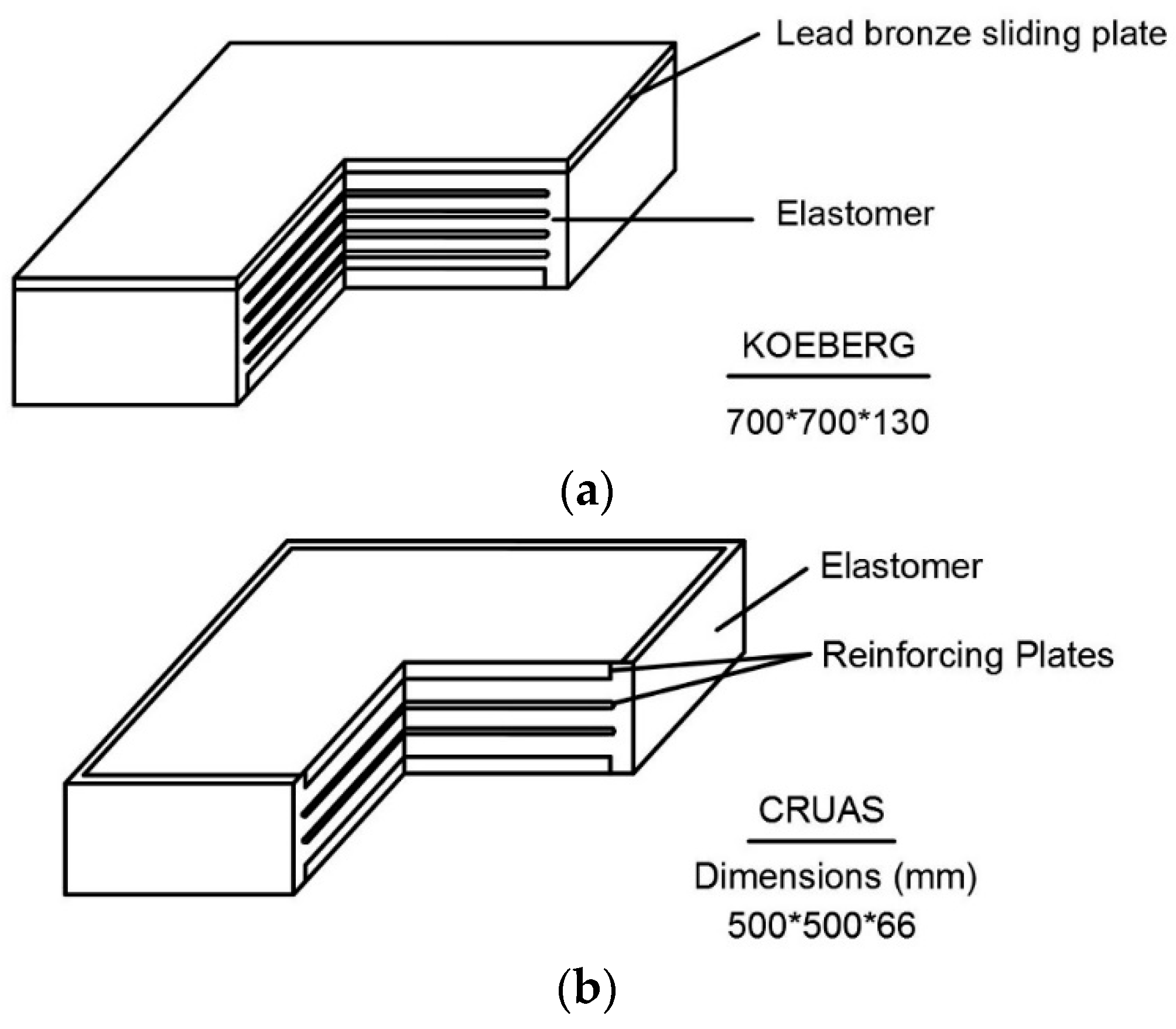
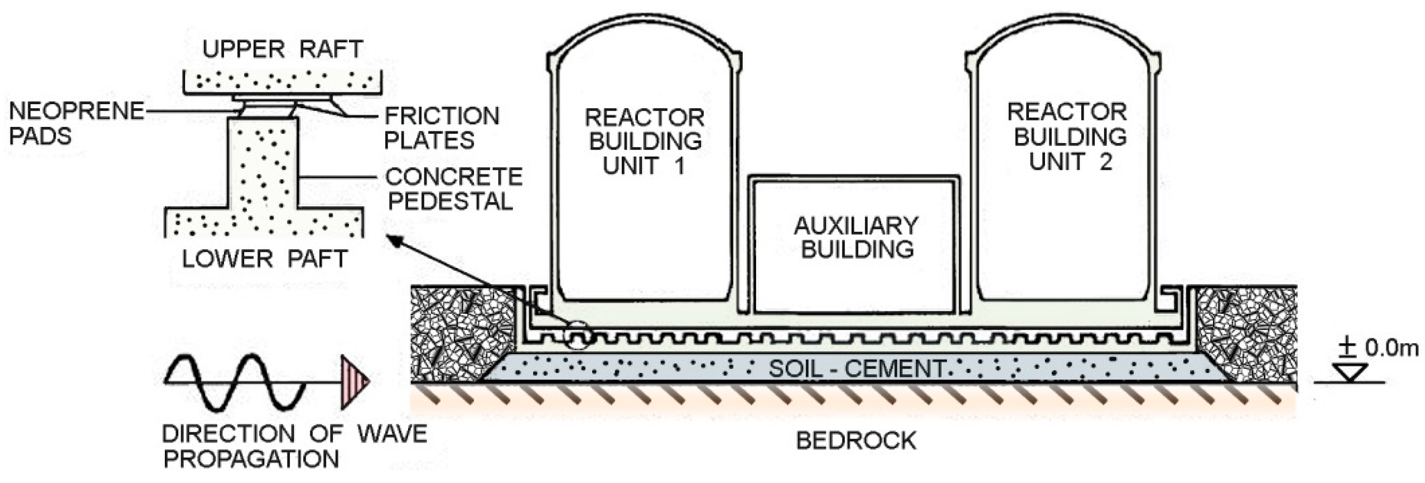
For the Koeberg NPP, 1829 isolators, which were mounted on 490 pedestals, were used to support the common mat under the two adjacent reactors. Similar to Koeberg, 900 isolator units were used for each of the reactors at Cruas [
7]. Sketches of the bearings used at the Koeberg and the Cruas nuclear power plant are shown in
Figure 2. The isolators installed in the Koeberg and Cruas NPPs are no longer in widespread use today [
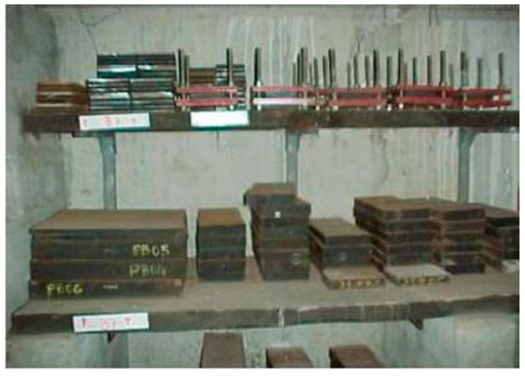
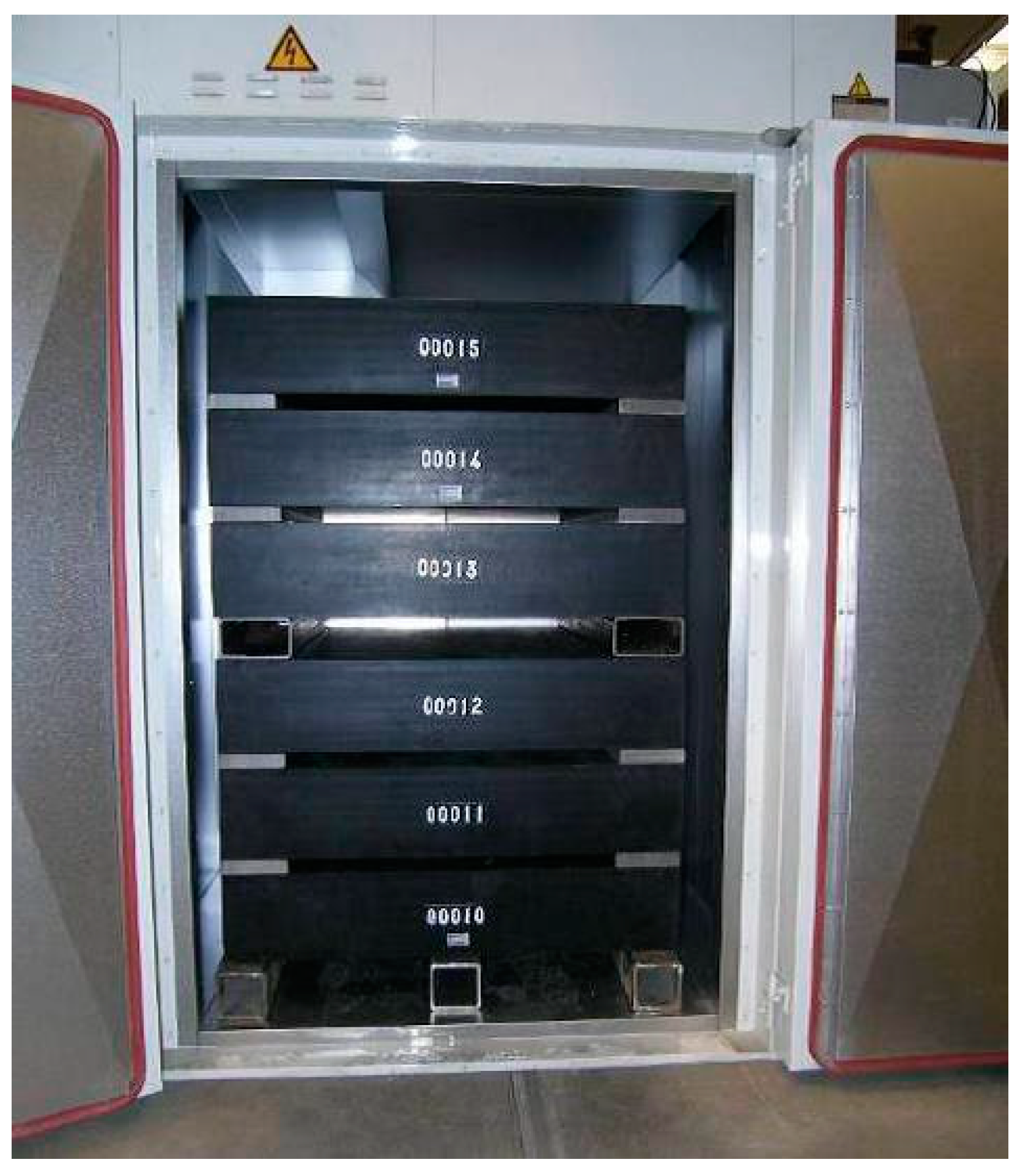
8]. The synthetic neoprene used is now known to stiffen with age, which changes the properties of the isolation system with time. In terms of repairs to the isolation system, no major work has been required to date at the Koeberg and Cruas NPPs. However, testing of the isolation bearings has been in progress for the last 28 years and periodic testing of spare isolator blocks has also been done at Cruas. The tests are completed by simulating in situ conditions. To do this, multiple sample isolation blocks have been post-tensioned to impose the same stresses as in the active bearings and stored in the same seismic vault as the active bearings. These sample blocks are then tested to identify any changes in bearing properties [
4].
Figure 3 shows some of the spare neoprene (elastomer) pads that are stored in situ for testing. After about 10 to 15 years, the physical tests of the neoprene (elastomer) material indicated signs of hardening. Based on the last reported testing of the bearings in 2005, the stiffness of the neoprene pad material had increased 37% since the time of construction. The expected increase at that time when considering standard aging estimates was 30%. The difference between expected and actual stiffness is believed to be accounted for in the design margins for the plant [
9]. While some hardening of the neoprene was detected in these tests, the measured shear modulus remained within the design limits. Due to the stiffening of the elastomeric material used, sliding would be expected to initiate at a slightly smaller lateral displacement of the bearing. To date, the seismic conditions in the area of the Koeberg plant have not resulted in movement in the system.
In the sliding isolation system of the Koeberg NPP, stainless steel in contact with bronze was used. Sixty sample bearings were stored in the same environment as the isolation bearings in prestressed rigs. After 14 years of service, those sample bearings were retested [
10,
11]. On average, the initial (static or breakaway) coefficient of friction of the bearings was increased by 68%. But the coefficient of friction of the sliding component of the bearing system has since stabilized due to the application of grease at the interface between the two sliding surfaces in order to reduce the likelihood of corrosion and the stoppage of ground water leaks into the seismic vault. The coefficient of friction also remains within the design limits. The grease, which is used as a lubricant, is stored in dimples from where it is extruded to the sliding interface under hydrostatic pressure. Dimpling is important for extending the effective life of the lubricant since approximately 30% of the apparent contact area is covered by dimples [
12]. The main components of grease are oil or synthetic fluid (approximately 80 percent or more), a thickening agent (typically soap at approximately 10 percent), and additives (antioxidants, anticorrosion agents, etc. at less than 10 percent) [
8]. Additionally, the grease coating applied to the interface between the two sliding plates has degraded over time. The older coating was removed and reapplied as part of system maintenance [
4]. Stick-slip phenomena were evident during laboratory testing of the sliding surface of the bearings. This is not uncommon in certain types of sliding friction devices. Since the measured bearing properties have remained within the original product acceptance criteria, no bearing repair or replacement has been necessary. Reports shows that this particular bimetallic friction interface used for Koeberg is no longer used in seismic isolators.
For transportation and other applications, many isolators and supplemental energy-dissipation devices are subjected to substantial wear testing. In such tests, small amplitude and low-speed cycles (consistent with motions of the device induced by thermal and service operations) are imposed. In many cases, devices are forced to undergo 5, 10, or even more kilometers of cumulative motion without substantial changes in properties before being subjected to large cycle excursions simulating earthquake effects. Generally, the isolation and damping device manufacturers interviewed have indicated little difficulty in satisfying such requirements.
Other age-related effects could influence the behavior of isolators. For instance, corrosion may occur on sliding surfaces. Thus, tests where contaminants are placed on the sliding surfaces and corrosion is accelerated by elevated temperatures and other means are frequently used to ensure adequacy of in-service properties in major projects. In the case of elastomeric bearings, exposure to light, ozone, and elevated temperatures is used to simulate aging effects.
Figure 4 shows a photograph of the aging test conducted on the bearings. Accelerated aging tests were performed by storing the bearings at an elevated temperature based on the Arrhenius law. According to the Arrhenius law, 18 months of an elevated temperature was equivalent to 70 years. The test method corresponds to ISO 11346 standards [
13,
14].
Investigations of the Koeberg NPP was made to determine the effect of aging on the bearing system. To conduct this aging study, it was assumed that the bearing system would need to remain operational during at least 30 years of exposure to aggressive environmental conditions. The aging study used a French method as well as an accelerated corrosion test procedure developed by the U.S. military. The aging tests indicated that the bearing would slightly increase its frictional resistance with age to a coefficient of about 0.2 [
6]. This was believed to be an acceptable increase based on other aspects of the investigations. The aging tests also established the likely bounds regarding changes in properties of the elastomeric pad over the expected life of the plant.
Thus, it is desirable to use isolation and dissipation systems with long histories of application and to carry out appropriate test sequences to assess aging effects. Unfortunately, many types of accelerated aging tests involving elevated temperatures and harsh short-term environmental exposures may not fully predict the aging effect.
2.2. Radiation Effects
Incorporating isolation systems in NPPs raises questions about the impact of radiation on the materials used in isolation bearings and energy-dissipation devices. Over the majority of the system’s life span, exposure levels to radiation are expected to be low since the isolators will be housed and shielded in a seismic vault reasonably far from the radiation sources. In such cases, the exposed bearing or energy-dissipation device will need to withstand the ground motion response spectrum (GMRS) or extended design basis (EDB) ground motion response spectrum (EDB GMRS) event.
In probabilistic risk assessments (PRA), a core melt scenario following an earthquake might be considered. Taking the Koeberg NPP as an example, which is shown in
Figure 5, the isolation system is located under the reactor buildings, auxiliary structures, and the two primary diesel generators. In such a case, the corium might be postulated to melt through the upper raft into the seismic vault, which, in turn, is exposed directly to the atmosphere. This is a distinct safety issue that may require action depending on the PRA requirements. To the authors’ knowledge, the level of radiation exposure for an isolation system has not yet been quantified. The consequences of any such radiation and thermal exposure regarding the seismic response during significant aftershocks would need to be evaluated.
In terms of likely radiation effects on devices such as seismic isolators, the focus is often placed on the damage created in the material properties from radiation-induced microstructural defects. In the most general terms, materials are composed of atom lattices. With the introduction of radiation exposure, atoms are knocked out of their positions or completely detached from the lattice, which deforms its microstructure. Considering the average energy of a fission neutron, as many as 50,000 atoms can be displaced [
16]. For metals, the recombination processes in the lattice might eventually fill 90%–99% of the dislocations. However, this mending process may be incomplete and leave permanent defects, which may cause changes in both microscopic and macroscopic properties. For example, a single defect could lead to the swelling of the lattice and alter both the material’s strength and ductility.
For metals, a number of mechanical properties are very important for the performance of the isolation system. A summary of the effects is shown in
Table 2 [
16]. As seen in this table, there are fluctuations between advantages and disadvantages created with the exposure to radiation. Today’s isolators are made with a variety of metals with varying alloys. As a result, severe radiation exposure gives rise to a large range of possible consequences. To completely understand the effect of radiation on mechanical properties, it will be necessary for the manufacturers to either provide their own radiation test results or disclose the type of material used in their metal components. Of course, studies are needed to identify radiation exposure scenarios.
Another major material to consider is the elastomer used in bearings. The summary of radiation effects on elastomeric materials is shown in
Table 3. There are two major effects resulting from the radiation exposure including cross linking and chain scission. Cross linking can best be defined as the creation of bonds between the polymer chains that compose the elastomer. Chain scission is the opposite to cross linking where the bonds are broken down, which degrades the polymer chains. Cross linking is dominant and would manifest as a hardening of the material.
A variety of composite and other materials are used in sliding bearings. Some published information is available on a few of the materials used. For example, in 1998, bids were being accepted for the Akkuyu nuclear power project in Turkey (which has since been abandoned). As part of a Canadian nuclear steam supply system (NSSS) supplier’s bid, they promoted the use of base isolation and cited studies by the Atomic Energy of Canada Limited (AECL) showing that Teflon, which is a material used in some sliding isolators, can withstand radiation doses as large as 1 Mrad (10,000 Gy) without any major performance issues [
7]. Today’s sliding isolators use a number of proprietary materials at the sliding surface. As a result, it will be essential to conduct studies on actual sliding surface materials to give better estimates of the acceptable radiation exposure.
Taylor Devices indicates that the silicon elastomeric material used in their dampers is insensitive to radiation. Information to substantiate these claims has not been reviewed.
Concrete may not be considered a major component of the isolation system. However, it is the material used not only to construct the seismic vault but also for the pedestals upon which the isolators are installed. For periods of time less than 50 years, studies have shown that low doses (<1010 neutrons/cm
2 or <1010 Gy gamma) do not have a major effect on concrete [
16]. For higher doses, there are variations in results. There are generally signs of deterioration with high radiation exposures including changes in the compressive and tensile strength as well as a volume increase.
Overall, there are definite effects on materials when exposed to radiation. However, given the circumstances of the location of the isolation system, this exposure is likely to be quite limited during normal operations. Radiation exposure of the isolation system during accidental scenarios and the effect of the isolation vault on these scenarios are beyond the scope of this paper. Nonetheless, testing to assess more thoroughly the long-term and transient effects of radiation on the properties of bearings or the materials used in bearings is warranted.
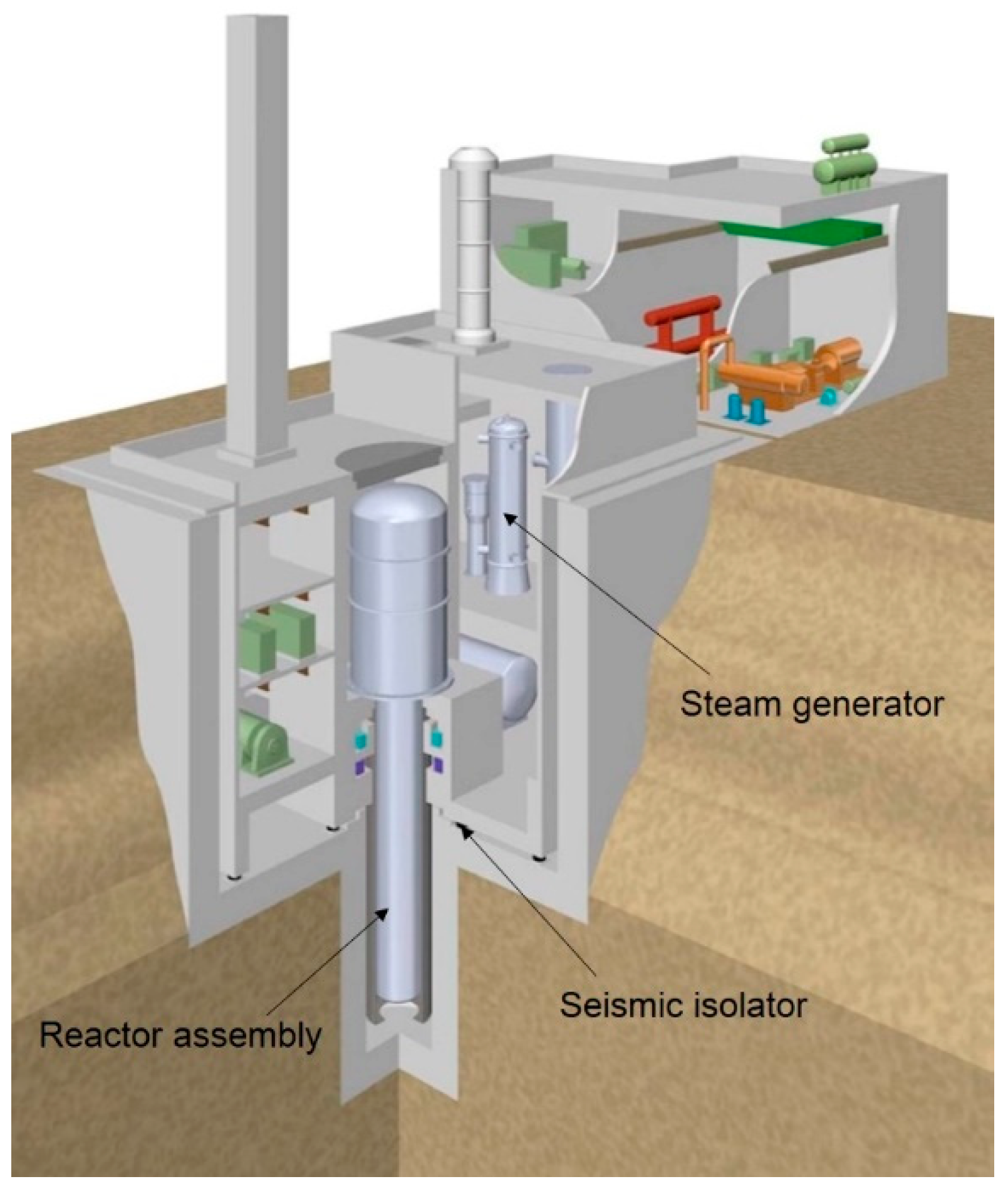
Based on current information, no special radiation protection equipment or uniforms are required to enter the vaults at the Cruas or Koeberg nuclear power plants. However, new designs that significantly alter the location of bearings and/or change the thicknesses of possible shielding materials should consider the effect of increased radiation on the isolation system. For example, the Super, Safe, Small, and Simple (4S) reactor is a small sodium-cooled modular reactor being developed by Toshiba. The seismic isolators are located where the normal radiation dose is low and are protected by a shield wall. A schematic cross section can be seen in
Figure 6.
2.3. Other Environmental Effects
A number of other environmental conditions could impact the performance of the system.
2.3.1. Thermal Effects
There is a potential for major changes in temperature within the seismic vault. In the case of normal conditions, EDF tested elastomeric bearings under a constant 40 °C climate. Even at this elevated temperature, the bearing still showed excellent behavior [
5]. The average measured ambient temperature in the seismic vault at the Koeberg NPP is significantly less (5 °C to 10 °C) than the outside atmosphere. Thus, the ambient temperature exposure for the bearings is likely significantly less than those used in the thermal tests conducted by EDF [
4].
Aging effects would be expected to accelerate during sustained, elevated temperatures. The internal temperature of bearing materials associated with energy dissipation tends to increase as isolation bearings move during seismic excitations. Thus, many studies of the properties of bearings at elevated temperatures have been conducted. In general, the strength of lead and friction liners tend to decrease as temperature increases and elastomeric materials soften. Thermal barriers are frequently used to protect isolators from the effects of transient elevated temperatures caused by fire.
Concrete is also known to suffer changes in properties due to elevated temperatures. For instance, water loss can lead to decreased compressive strength accompanied by changes in the elastic modulus, creep resistance, conductivity, and diffusivity [
18]. These signs of degradation tend to appear above 95 °C, which would be considered an extreme level of temperature for the system. Additionally, the damage to the material increases with temperature and time. Under an accident scenario involving the seismic vault, there is the potential to see a rapid increase in temperature to levels that might affect the properties of the isolation system assembly including the supporting concrete.
Low temperatures may have a strong effect on mechanical properties of elastomeric materials. Both the stiffness and strength of elastomeric bearings will be increased by a low temperature. Roeder et al. presented a comprehensive review of this problem [
19]. In general, low temperature results in crystallization stiffening, which is time-dependent, and instantaneous thermal stiffening, which is achieved within the time needed for thermal equilibrium. The elastomer becomes brittle and its mechanical and physical properties display rapid and significant changes when the temperature falls below the glass transition temperature. The glass transition temperature of natural rubber is about 55 °C. Roeder et al. concluded that, in Alaska, in limited parts of the continental United States, and in much of Canada, thermal stiffening in elastomeric bearings is likely to be a serious problem. When temperature drops below 0 °C, crystallization is a problem. As measured by smaller percentage increases in shear modulus, at low temperatures, natural rubber shows superior behavior to neoprene. Moreover, time-dependent stiffening under a low temperature is more pronounced for rubbers with larger shear moduli [
8].
2.3.2. Fire
The EDF studies leading to the use of isolation in the Cruas and Koeberg nuclear power plants determined that, in the case of a fire, the elastomer used will not show any signs of deterioration [
18]. Although the elastomer is not affected, concrete may be extensively damaged in a fire. The effects of fire on concrete are, in part, associated with differential volume changes between locations in the concrete at different temperatures and between the concrete and reinforcing steel. In the case of fire, temperatures may become sufficiently high that free water in the concrete could convert to steam, which would cause micro-cracking in the concrete interface and lead to changes in durability. In severe cases, spalling could occur, which would require extensive concrete repair [
20].
Since the bearings are part of the vertical load-carrying system, they may be considered non-redundant and may need to be fire-protected. In the building industry, fire protection requirements vary greatly, but various methods of fire protection (fire rate jackets, nonstructural fire rated furring, etc.) are often used. These enclosures can make periodic visual inspection difficult. In many cases, engineers may successfully argue that there is little fuel in the vicinity of isolators so that fire protection is not needed or fire sprinklers are used.
2.3.3. Groundwater Level
One other environmental consideration is water infiltration of the seismic vault. In the interview with Kotze pertaining to the Koeberg nuclear power plant, infiltration of groundwater was a maintenance issue. One unexpected area of concern for the isolation system at the Koeberg NPP arose immediately after construction was completed. Groundwater infiltration into the seismic vault was detected. This problem was resolved by a series of waterproofing measures applied to the construction joints in the retaining walls and lower raft. The seismic vault is checked periodically to ensure that it is dry and that there is little potential for corrosion of the exposed sliding plates [
4].
In a recent visit to Cruas, one of the authors noted that rainwater was able to flow into the seismic vault. Sump pumps were used to remove this water and no evidence of corrosion of the metal portions of the bearings was noticed.
In the March 2011 east Japan earthquake, a few base-isolated buildings were located in the tsunami inundation zone. Although these buildings did not seem to be damaged by the tsunami, the seismic vaults filled with water. Due to the lack of electric power in the vicinity, it took two or more weeks to remove the water in several instances.
3. Quality Assurance
In considering a new technology for NPPs, it is extremely important to take into account the testing and quality assurance (QA) procedures of the manufacturers.
For buildings, details of a QA program are left to the engineer of record. In many cases, all bearings are tested and, in others, only a fraction are tested. In some countries, QA tests involve sampling of only the materials used in the bearings and they do not involve tests of the actual bearings. Where bearings are physically tested as part of a QA program, engineers specify the maximum displacement capacity of the bearings. Some stipulate the design-earthquake-level displacement and others use different displacements. As with prototype testing, different displacement rates are specified and they range from slow to real-time testing. Thus, a QA program needs to be established based on project performance requirements.
It should be noted that most manufacturers can make only a few isolators a day (5–10) and, that for a facility requiring many isolators, prototype testing, manufacturing, and QA testing may take as much as a year or more. Since the bearings are among the first items to be installed, decisions on the type and properties of isolators need to be made early in the design process.
EPS conducts 100% of all manufacturing at their Vallejo, California location and, for DIS, the materials used in the assembly process are monitored continuously and tested at their manufacturing sites even before reaching the assembly location in Nevada.
Currently, the American Society of Civil Engineers (ASCE) 7 and the American Association of State Highway and Transportation Officials (AASHTO) require two prototype bearings of each type used on a project to be rigorously tested [
21,
22]. In addition to these tests, the need for quality control tests is left to the discretion of the design engineer. In the case of DIS and EPS, both companies test 100% of the bearings under average dead loads and design displacements.
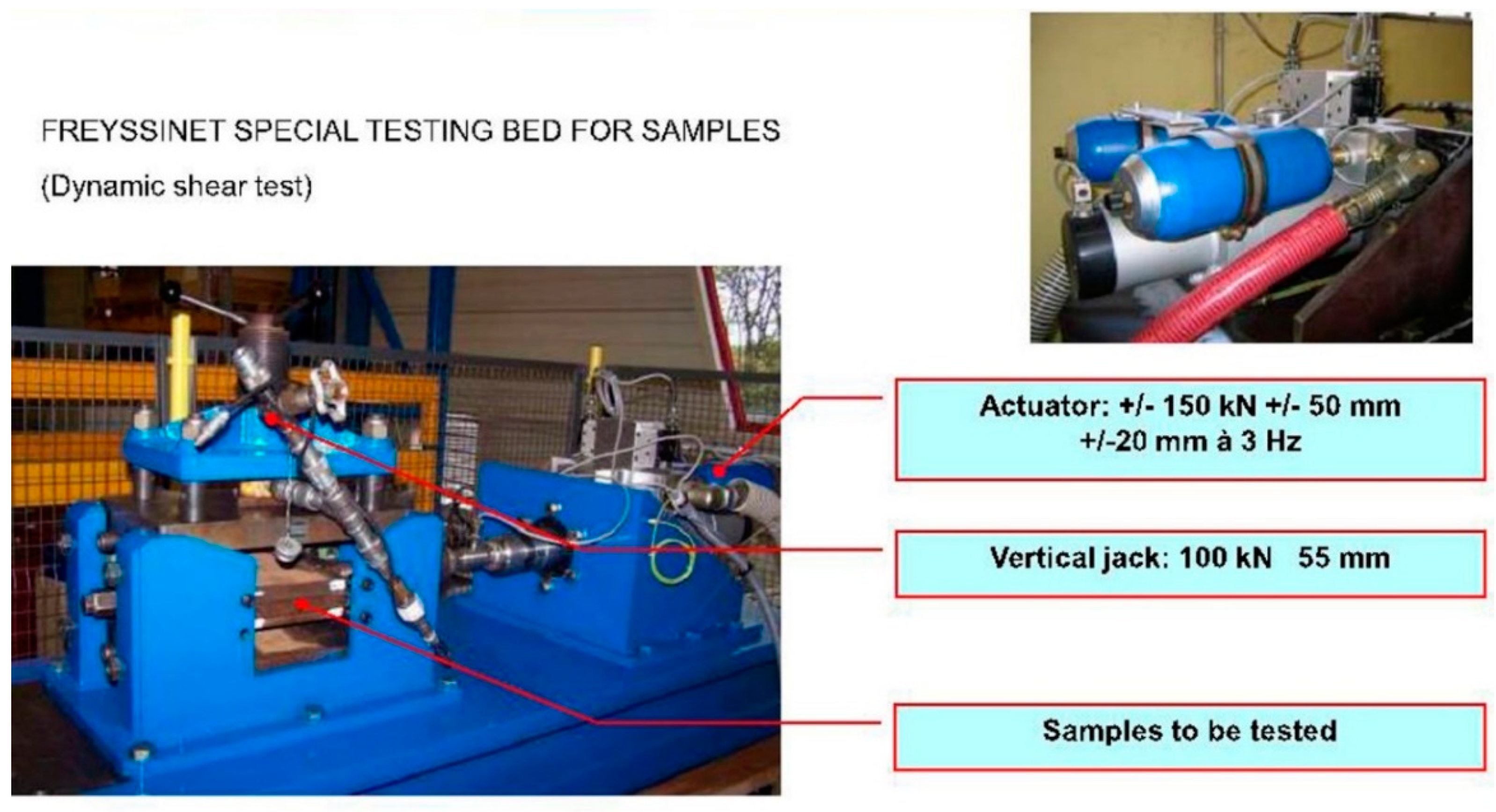
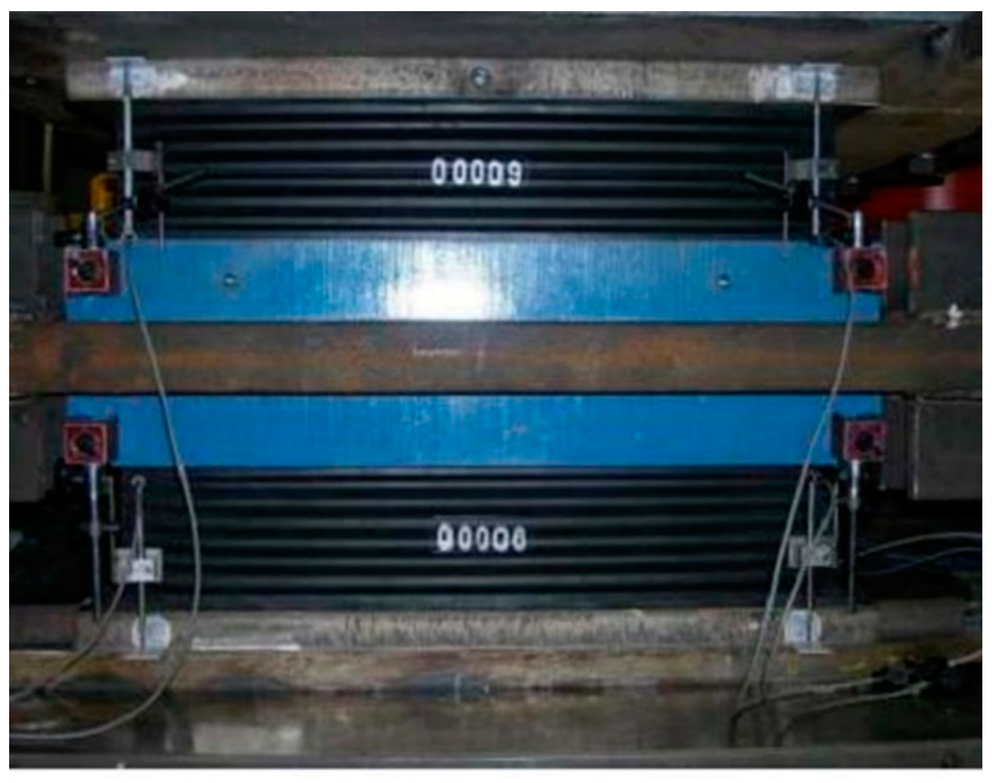
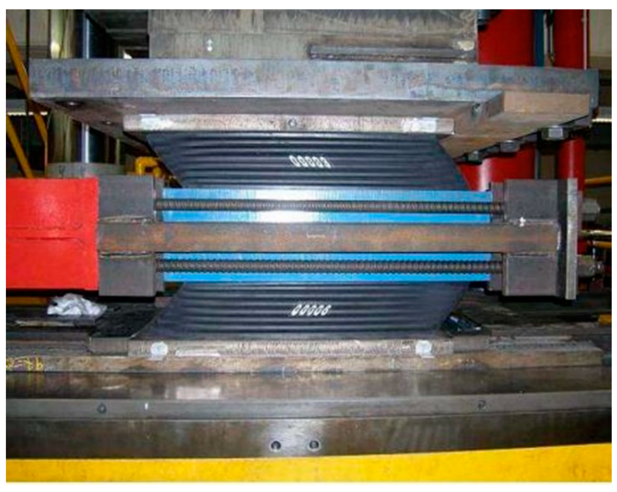
The International Thermonuclear Experimental Reactor (ITER) is an international collaboration between the European Union, the United States, the Russian Federation, and Japan. An extensive testing plan was invoked at the ITER to evaluate the bearing system selected in terms of mechanical properties under both static and dynamic loading conditions. Tests were done on full-scale bearings as well as samples of different parts of the bearings [
13]. The tests conducted assessed the static, dynamic, and long-term and aging properties of the bearings. The goal of the tests was to define key design parameters such as shear modulus, damping, creep moduli, and aging parameters.
Figure 7,
Figure 8 and
Figure 9 depict the various apparatuses used for these test procedures.
Note that, even though there are design criteria for seismic isolation systems currently, there are no standards that set protocols for manufacturing procedures and certification of bearings. This issue should be addressed in the future.
4. Design-Related Issues
Seismic isolator manufacturers work with the client to develop a design to meet their project needs. The major component in the decision-making process is the performance criteria established for the project.
Several codes, standards, and guidelines already exist in the United States that are applicable to seismic isolation of safety-related nuclear structures even though they were not written specifically with seismic isolation in mind. These were prepared by the ASCE, the American Concrete Institute (ACI), the American National Standards Institute (ANSI), the American Institute of Steel Construction (AISC), and the Nuclear Regulatory Commission (NRC).
Outside of the United States, there is a long history of research and development focused on seismic isolation technology applied to nuclear facilities. There are various standards available in Japan and Europe related to the design of NPPs. Two of these standards are particularly focused on based isolated nuclear power plants: JAEG 4614-2000, Design and Technical Guideline of Seismic Isolation Structure for Nuclear Power Plant in 2000 and JNES-SS-1001, Regulatory Guidelines for Reviewing Seismic Isolation Structures (2009 edition) in August 2009.
To date, detailed guidelines applicable to the design of isolated NPPs are not available outside Japan. However, current efforts by the NRC and ASCE in the United States and International Atomic Energy Agency (IAEA) at an international level are rapidly addressing this situation. ASCE 7-16 and the Multidisciplinary Center for Earthquake Engineering Research (MCEER) report 15-0005 provides guidance on bounding analysis of an isolation system for design [
23,
24].
This has led to two types of approaches being used in practice. In one case, engineers work to develop a design that satisfies the minimum requirements of the relevant code. This results in a code-compliant design that may have a relatively small initial construction cost. However, it may be unable to achieve the required performance goals, which may result in subsequent costs associated with repair and business interruption. The second approach establishes specific project goals and engineering efforts are directed to develop and verify designs that achieve those goals with the desired confidence. This later approach tends to require close collaboration between the design team and the manufacturer of the isolation system. Both DIS and EPS mentioned insufficient collaboration with the design team as one of the major issues they face.
Another complication that frequently occurs is the timing of the design collaboration. In some projects, manufacturers are not consulted or included in the design process until a major portion of the structural design has been completed. Manufacturers believe that their expertise with seismic isolation and their experience in applying isolation to hundreds or thousands of situations is not adequately taken advantage of in the engineering design process.
5. Construction Issues
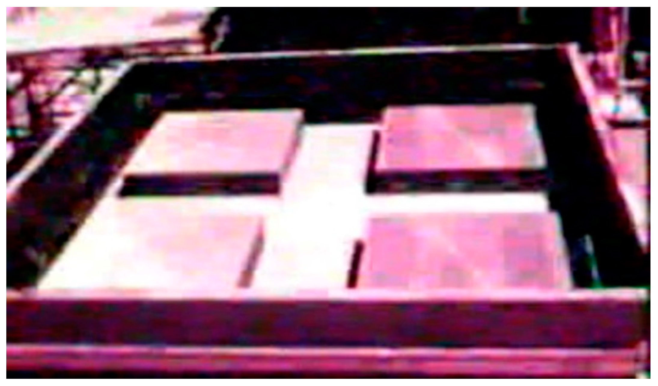
In the case of construction, achieving required tolerances is a major consideration. As seen in the construction of the Koeberg plant, before shipping the prefabricated bearing assemblies to the construction site, the quad-bearing units were rechecked to ensure that all four bearings lay on the same plane. The flatness checks were carried out using very precise levels with an accuracy between 20 and 50 microns [
6], which is shown in
Figure 10.
Figure 10 and
Figure 11 are images taken from a video. Therefore, the resolution is low.
To line up the centers of the bearings and the stainless steel plates upon which they were intended to slide, a positioning template plate was placed over the prefabricated slab-bearing unit. Before placement of the steel plate units, horizontality of the installed slab units was double-checked to ensure satisfaction of the specified tolerance of 1 mm [
6].
Figure 11 shows the installed prefabricated units with the perimeter template plates installed.
Careful attention was placed on ensuring the horizontality of the isolator assemblies. The bearings were placed at the same level to make sure that there were no unbalanced forces created in the system when seismic motions were applied.
During a recent visit to the seismic vault at the Cruas NPP by one of the authors, it was noted that the bearings near the reactor building have sustained differential vertical shortening across multiple bearings on a single pedestal. The innermost edge of the bearings on a pedestal closer to the center of a reactor building are noticeably shorter than the outermost edge of the bearing located on the same pedestal farthest from the center. EDF was aware of this situation and did not believe that this differential straining would adversely affect the behavior of the isolation system.
Regarding the present situation, with every isolator shipment, both DIS and EPS provide clients with specific instructions pertaining to installation, operation, and maintenance of the isolators. In some cases, they work with engineers and contractors to develop project-specific approaches. In general, the construction process for the seismic vault and installation of the isolators does not require any special equipment that would not already be readily available on site.
Another important aspect of isolating the plant was the treatment of piping systems that crossed the seismic gap. All affected piping in the Koeberg plant was fitted with either flexible hose or rubber joints to allow flexibility in the system [
4].
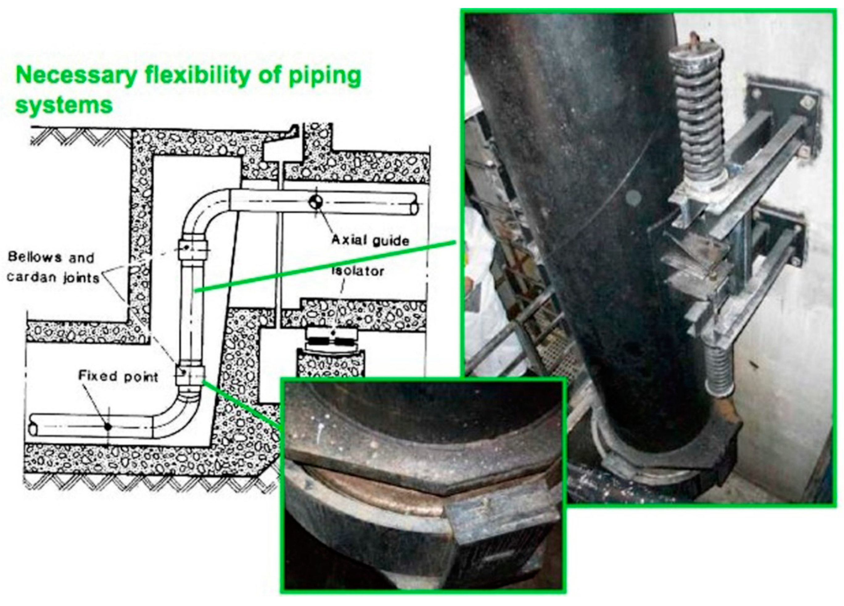
Issues related to piping systems crossing over the seismic gap were addressed in a manner slightly different from the approach used at Koeberg NPP. For Cruas NPP, flexibility was increased in the piping system by the use of bellows and Cardan joints. Cardan joints are used in a rigid cylinder that allows the cylinder to bend in any direction [
25]. Bellows are a piping expansion joint intended to absorb thermal movement and vibration in piping systems that transport high-temperature materials such as steam. An example of the piping set up found in the Cruas NPP is shown in
Figure 12.
6. Operations and Maintenance
Isolation systems do not require extensive maintenance. Based on the manufacturer’s recommendations, the isolators should be visually inspected every few years, which coincides with the inspection of the supporting structural systems to make sure that water leaks or other moisture problems have not occurred. This leads to the corrosion of the metallic parts of a bearing (generally stainless steel galvanized or covered with zinc-based paints) or they have not suffered other accidental damage. In some cases, clients may choose to conduct various tests throughout the life span of the system.
The Koeberg plant operator developed and implemented a program to monitor and test the isolation system to ensure its effectiveness. The inspection regime consists of two regularly repeating activities:
The Koeberg plant operator developed these procedures with input from the regulatory authority and with the knowledge of EDF. Some, but not all, of the inspection protocols are aligned with those used by EDF. In some cases, the plant operator has carried out benchmarking tests with EDF.
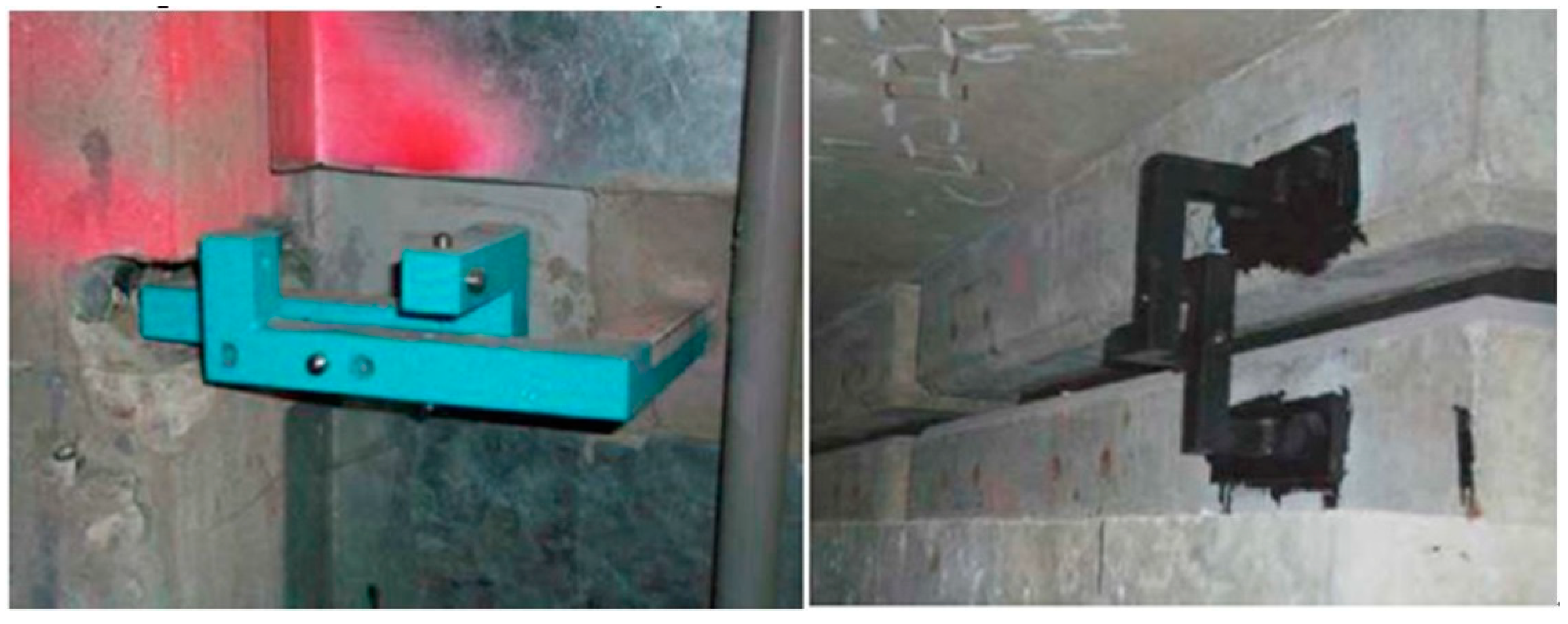
As done at Koeberg, similar testing of the isolation system has also been applied to the Cruas NPP. A mechanical monitoring system has been installed in several locations at the Cruas NPP to assess movements of the isolation system. Using simple displacement indicator devices similar to those shown in
Figure 13, the plant operator is able to monitor settlement, pedestal verticality, and differential displacements in the isolation system.
Overall, the operations and maintenance will have variations based on the manufacturer, type of bearings, and application of the system. The NRC Regulation (NUREG) on technical considerations for seismic isolation of NPPs indicates that testing of the sample bearing stored under load in the seismic vault should be conducted every 10 years. Such test procedures have been used for isolation systems in buildings, but it is less common now that more experience and a longer track record of bearing performance has been developed.
7. Conclusions
Seismic isolation is not a new technology, but it is being considered for a new application. At this stage, it is important to thoroughly understand how these systems work, how they age, and how to effectively maintain them to ensure optimum performance. In this paper, a number of topics have been reviewed including durability, maintenance, and even first-hand experience with designing isolation systems. The Koeberg and Cruas NPPs were based on the best available technologies and, in some respects, they are not the best examples of application of seismic isolation. However, as precursors, there are definitely lessons that have been learned in terms of design aspects as well as ways of maintaining the system over its lifetime. Future development and research in this area is warranted especially in terms of understanding the system’s role in an area of radiation and potential extreme exposure during accidents. By gaining a basic understanding of the system’s capabilities, future designs for NPPs should take into consideration these characteristics to help in the decision-making process.


