1. Introduction
Working conditions in underground mining plants are distinctly different from the conditions on the surface. Their major characteristics are the scattering of workplaces over a large area [
1] and a harsh working environment [
2].
Microclimatic conditions in mine excavations are determined by the physical characteristics of mine air. As the air passes through mine excavations, its parameters and composition change as a result of the heat supply from both natural and technological sources known as artificial sources [
3,
4]. Heat flow from natural and artificial sources into mine excavations was described in detail, among others, by Hemp and Rawlins [
5]. The resulting high temperatures of air in mine excavations, coupled with an equally high level of humidity, causes a serious deterioration of microclimatic conditions [
6]. Bad microclimatic conditions affect miners underground, causing reduction of perception, concentration, attention, and perceptiveness [
7]. This negative influence of temperature and humidity on the human body is referred to as the climatic hazard [
4].
The temperature of mine air changes as a result of such processes as the compression of air in the fields of gravity and the exchange of heat and moisture between the rock-mass, additional local sources of heat, and the moving air [
8]. The additional sources of heat are primarily machines and devices, especially electrical and diesel drives. Changes of temperature are influenced to the greatest extent by the exchange of heat between the air and rocks surrounding a mine excavation [
9]. The type and intensity of this exchange is determined by many factors, the most important of which is the depth and the resulting virgin rock temperature [
8,
10,
11]. The distance covered by the air from the surface to the workplaces underground can usually extend over several kilometres in Polish coal mines [
12]. During this passage, the transfer of heat and mass of moisture occurs.
Microclimatic conditions in deep underground mines are also influenced by an appropriate design of mine excavations, the haulage routes, and the deployment of electrical devices, as well as by implementing a rational ventilation system aimed at minimizing the heating of air reaching the workplaces.
Ensuring the stability of microclimatic conditions in mine excavations over time by implementing mine ventilation and cooling systems in deep mines is a serious challenge.
2. Cooling Solutions for Air in the Polish Mining Industry
To provide cooling of air in a large number of workplaces of the deep mine and to satisfy the need for a greater cooling capacity, it becomes necessary to install cooling plants on the surface or underground. Saving energy should always be taken into account when designing cooling systems [
13]. A number of factors should be taken into account when considering cooling systems in underground mining areas [
14]. A review of factors necessitating the widespread use of refrigeration in deep mines, and of practical considerations which dictate where the plant must be located was described, among others, by Whillier [
15] and Ramsden et al. [
16]. Bluhm and Smit [
17] have presented requirements that should be taken into account when planning ventilation and refrigeration in deep mines.
As the number of cooling units installed underground is rising, a point is reached when it is no longer possible to reject condensation heat into the return airway in a mine. Once this threshold is reached, condensation heat must be transferred onto the surface via water.
Currently, two trends can be observed with respect to the technology of air cooling used in the Polish mining industry [
18,
19]:
- (1)
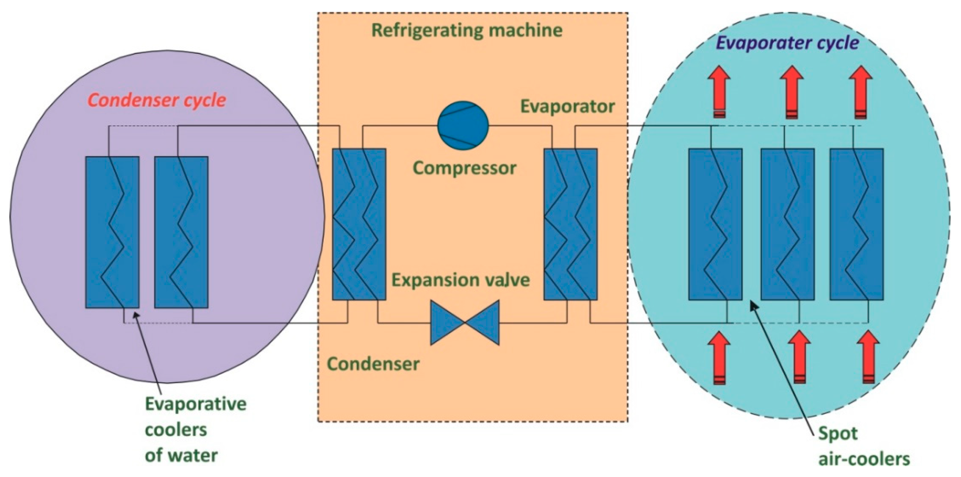
Implementing movable refrigerating machines, which are either direct or indirect air-cooling units, or using stationary refrigerating units, which create a cooling plant and chill water in closed circuits for use in the cooling-coil heat exchangers as spot air-coolers. The heat of condensation is usually rejected into the main return airways or to water, which is drained by the de-watering system of the mine. In the Polish mining industry, these cooling systems are called “a local” or “group” cooling system, respectively; and
- (2)
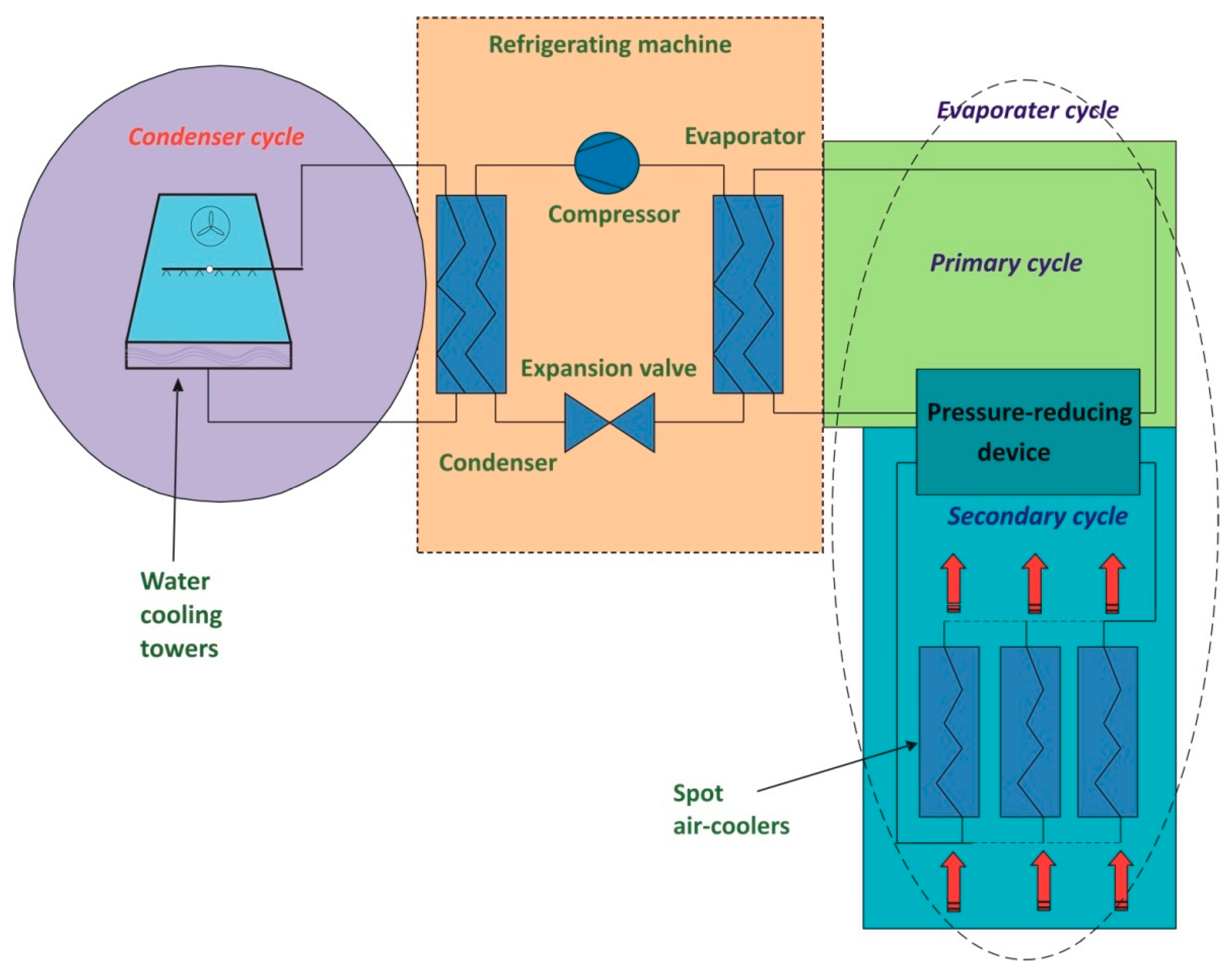
Implementing “a central” cooling system by installing centralized refrigerant plants on the surface or underground, from which chilled water is directly distributed to spot air-coolers in the mining districts.
Schematic diagrams of these cooling methods are presented in
Figure 1 and
Figure 2.
A stepwise growth of deterioration of climatic conditions is observed in most underground mines in Poland, caused by the necessity to extract deposits at increasingly deeper levels.
The cooling systems described above involve using cooling units that can be classified under the following categories according to the transfer medium of the heat exchange (cooling medium):
- -
Individual refrigerators, which are direct air-cooling units consisting of direct-expansion coils with the refrigerant inside the tubes of the heat exchangers;
- -
refrigerating machines in cooling plants operating indirectly by chilling water (the temperature of the chilled water is between 1.5 and 5.0 °C);
- -
ice-makers producing artificial ice (used as a hard ice transported to the underground thermal storage system or used to produce ice water or ice slurry); and
- -
ice-makers producing and transporting ice slurry to mine excavations.
Both refrigeration units are utilised in Polish underground mines, namely, units operating directly and operating indirectly by chilling water. These mobile refrigeration units are currently being phased out, and refrigerant plants either on the surface or underground are built with refrigeration machines to chill the water, which, as a coolant, is supplied to spot air-coolers. Air-coolers as air-to-water exchangers are connected to the chiller machines by a piping system. The network of pipes makes a water reticulation system.
Underground cooling plants are equipped with compression-type refrigeration machines. The most commonly used refrigerants are R134a and 407C refrigerants. The condensers of refrigeration machines are water cooled. Next, the water is chilled in the evaporative coolers of water, which are installed in mine excavations.
Different refrigeration machines are used in surface stations. Mostly, these are compression-type refrigerators with the refrigerant, R717. The evaporative condensers are used to reject the condensation heat in this case.
There are also surface plants in Polish mines that are equipped with several refrigeration machines operating in a cascade system. Refrigeration units with the refrigerant, R407C, are then the first stage of cooling water, and refrigeration machines with the refrigerant, R717, are the second or third stage, respectively.
There are two mines in the Polish mining industry in which surface cooling plants are part of Combined Heating, Cooling, and Power Plants (CHCP) systems. Absorption cooling units are used in the cascade construction together with the compressor units, with the R717 refrigerant in this case.
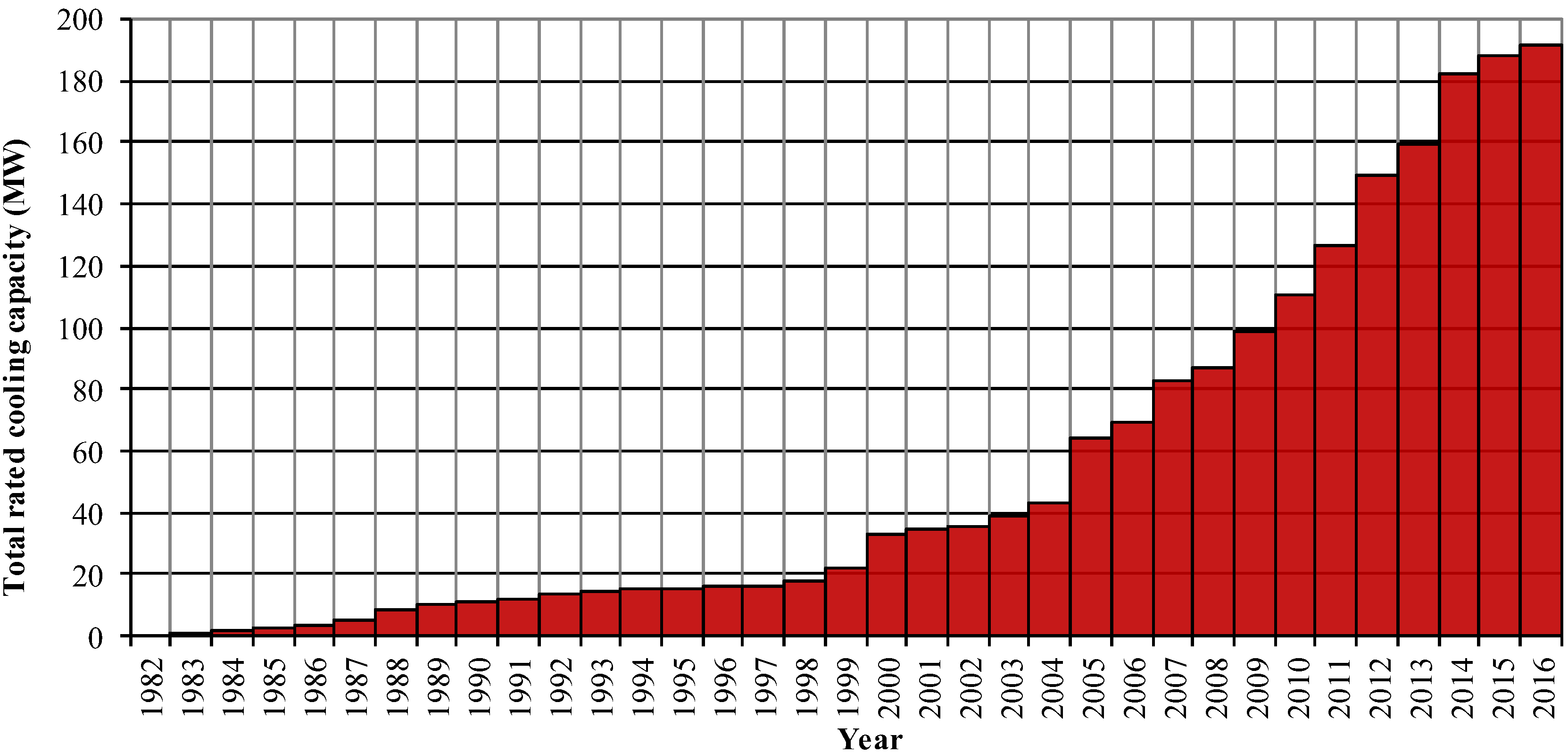
As of the end of 2016, the rated cooling power of the cooling units installed in the Polish mining industry was 193 MW. The growing values of the total cooling capacity are presented in
Figure 3.
An adequate design of the mine cooling system at the planning stage should guarantee maximum efficiency of heat exchange in mine excavations to satisfy environmental requirements. In Polish mines, a lower efficiency of both “group” and “central” cooling systems was observed after a certain time from their commissioning. This became the basis for conducting research on the efficiency of these systems. The efficiency of a cooling system is determined by the quotient of the heat flux received in the cooling coils and the available cooling power of refrigeration machines connected to the system.
Therefore, based on the measurements conducted during the study, the authors discuss the factors that diminish the efficiency of the cooling system in underground mines
3. A Study into the Efficiency of Air Cooling Systems
3.1. Research Objectives
The objective of this study was to determine the efficiency of the cooling systems in Polish hard-coal mines.
The efficiency of the cooling systems in Polish mines was assessed based on in-situ tests in six mines. In two cases, there were installations with refrigeration plants on the surface, and in four, with underground refrigeration plants. In the underground plants, the heat of condensation was transferred to the return airways in the mines using evaporative coolers of water.
The heat of condensation in the surface refrigeration plants is rejected into the outdoor air using evaporative ammonia condensers in one case, and mechanical draft cooling towers in the other case. Parameters of the tested refrigeration plants are presented in
Table 1.
To attain the objective, the following parameters of the tested cooling systems were determined:
- -
The cooling capacity of surface or underground refrigeration plants;
- -
the performance of spot air-coolers;
- -
thermal losses in chilled water reticulation systems;
- -
the technical condition of the system; and
- -
possible improvements of the efficiency of the cooling system.
The study involved measuring the cooling performance of both the cooling coils as well as the chiller machines. The measurement results allowed determining the factors affecting the actual efficiency of the cooling units.
The study consisted of determining the heat exchange balance in spot air-coolers. Tubular coil heat exchangers to transfer heat from air to water are used in the Polish mining industry. Cooling coils in gate roads were investigated in the water reticulation systems.
3.2. Methodology of Research
The measurements performed in the tested systems were aimed at determining the heat exchange balance in the in-direct air-cooling coils. To determine the balances, it was necessary to measure the physical characteristics of the chilled water in the closed-circuit piping networks. Measurements of chilled water parameters were made along the length of the water line of the particular installation.
Parameters of the water flowing out and flowing into both cooling plants and spot air-coolers near workplaces were also measured. Measurements were conducted for 62 spot air-coolers in the gate roads of six hard-coal mines.
Heat exchange in surface coil exchangers is connected with the enthalpy balances of the media flowing on each side of the surface, i.e., the mine air and the coolant. As a coolant, chilled water supplied and returned via a piping network is used.
The efficiency of this process depends on the physical characteristics of the air and water at the inlet of the air cooler.
The obtained cooling capacity of the spot air-cooler is linked to the enthalpy balance of the air and water circuits. According to
Figure 3, the balance can be expressed with the following formula:
where:
—is the stream of the air enthalpy at the intake of the air-cooler (upstream of the cooler’s fan), kJ/s;
—is the stream of the air enthalpy at the outlet of the air-cooler (considering the enthalpy of the water droplets carried by the air leaving the air-cooler), kJ/s;
—is the stream of the enthalpy of the water (leaving the coil regardless of the water drops in the air flowing from the coil), kJ/s;
—is the heat flux exchanged between the package of the air-cooler and the ambient air, kW;
—is the stream of the water enthalpy at the intake of the air-cooler, kJ/s; and
—is the stream of the water enthalpy at the outlet of the air-cooler, kJ/s.
Considering the air-cooler as a cooling coil and a cooler’s fan, it is possible to determine the cooling capacity of the cooling coil itself:
where:
—fan heat gain, kW.
To calculate the heat balance of the spot air-coolers, it was necessary to measure the temperature and moisture content in the air upstream and downstream of the air-cooler and the volumetric air flow rate. Consequently, to identify the enthalpy of the water, the temperature of the water had to be measured at the intake and outlet of the air-coolers, and the volumetric water flow rate had to be gauged.
To evaluate the efficiency of the cooling the air, the following physical characteristics were measured:
- (a)
The dry-bulb and wet-bulb temperatures at the intake of the cooler’s fan by the Assmann Psychrometer;
- (b)
the dry-bulb and wet-bulb temperatures at the outlet of the air-cooler by the Assmann Psychrometer;
- (c)
the dry-bulb and wet-bulb temperatures between the outlet of the fan and the intake of the cooler by the Assmann Psychrometer;
- (d)
the mean velocity of the air at the cross-section of the outlet of the air-cooler and the inlet of the cooler’s fan using a vane anemometer, µAS;
- (e)
the temperature of the water at the intake and at the outlet of the air-cooler using a submersible sensor with a PT-100 probe;
- (f)
the water flow rate through the air cooler using an ultrasonic flowmeter, “Alfine-PF220”, mounted on the external surface of the pipe; and
- (g)
the absolute pressure as measured in the place where the air-cooler is installed using a portable absolute pressure transducer, µBAR.
During the measurements, the air-coolers and the piping system were evaluated with respect to their technical condition.
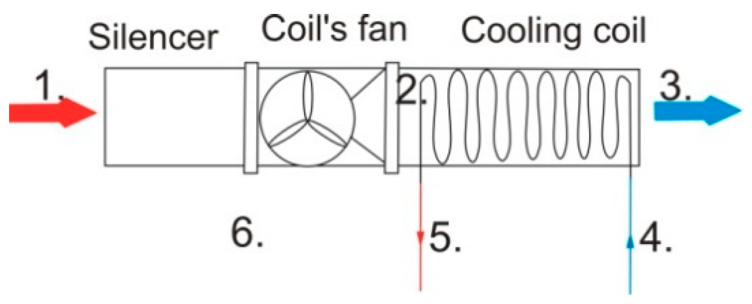
Figure 4 presents the measuring points for the spot air-coolers under investigation.
The following air and water parameters were measured at the measuring points marked in
Figure 4:
- (a)
Air temperature as measured by the dry-bulb and wet-bulb thermometers at the inlet of the coil’s fan, and the average air velocity at the cross-section of the inlet to the coil’s fan;
- (b)
air temperature as measured by the dry-bulb and wet-bulb thermometers at the outlet of the cooler, and the average air velocity at the cross-section of the outlet the coil;
- (c)
air temperature as measured by the dry-bulb and wet-bulb thermometers between the outlet of the fan and the intake of the cooler;
- (d)
chilled water temperature and flow rate at the intake of the cooling coil;
- (e)
chilled water temperature at the outlet of the coil; and
- (f)
barometric pressure as measured in the place of the coil’s location.
The calculations made on the measurements in the air circuit do not fully allow consideration of the condensation of water. A satisfactory approximation for mining purposes, where even the intake air to the coil is close to saturation and does not usually cover a wide range in temperatures, is to consider the differences between the wet-bulb temperature of the air and the water temperature as the driving force for heat transfer [
20]. The performance of spot air-coolers was calculated by using the formulae:
and:
where:
—is the mass flow rate of water, kg/s;
—is the mass flow rate of dry air, kg/s;
cw—is the specific heat of water, kJ/(kg·K);
tw—is the difference between entering and leaving water temperatures, °C; and
Sa—is the changes in sigma heat between inlet and outlet of air, kJ/kg.
Sigma heat is the enthalpy of water vapour content associated with the unit mass of dry air, calculated as if the water vapour were present as liquid water at the wet-bulb temperature [
10,
20,
21,
22].
The difference between the two calculated values, , allowed a check of the data for errors. Obtained values were in reasonable agreement in the mining environment not exceeding 10%.
4. Results and Discussion
4.1. Balance of the Cooling Power
The results of the chilled-water parameters measurements in the refrigeration plants of the tested installations are presented in
Table 2.
While the measurements were being carried out, the cooling power generated by the refrigeration plants in the six hard-coal mines under analysis was 10,960 kW, the rated cooling capacity being 21,700 kW. The total mass flow rate of the water during the tests of all installations amounted to 294.7 kg/s. Assuming that the difference in water temperature in the evaporator cycle of underground plants should be 13 °C, and in surface plants 15 °C, the total power of all cooling plants should be 17,260 kW. The difference between the generated and the rated cooling power resulted from the fact that the heat was not transferred to a sufficient degree or—in the case of the group cooling systems—the condensation heat was not rejected in the evaporative coolers of water to a sufficient degree.
The generated cooling power was utilized in the following way:
- -
in spot air-coolers: 7380 kW;
- -
lost in the piping networks: 3580 kW; and
- -
in total: 10,960 kW.
The efficiency of the air conditioning was established using the index of the cooling power generated to the cooling power available in the air conditioning systems under analysis. The index of efficiency is presented in
Table 3.
The research presented here revealed that the air conditioning systems had an average index of cooling power efficiency of 34%.
Spot air-coolers analysed in the study did not reach their maximum levels of available cooling efficiency. Hard-coal mines fail to fully utilize the cooling power at their disposal because of the low levels of heat transfer in the cooling coils.
4.2. The Causes of the Low Efficiency of Cooling Systems
Based on the examination described above, the following fundamental obstacles to achieving a high level of efficiency were identified:
- -
Thermal losses in the piping network;
- -
inability of the spot air-coolers to reach the required cooling capacity; and
- -
problems with lowering air temperature linked to humidity.
The problems listed above are analysed and their underlying causes are explained in the subsequent sections below.
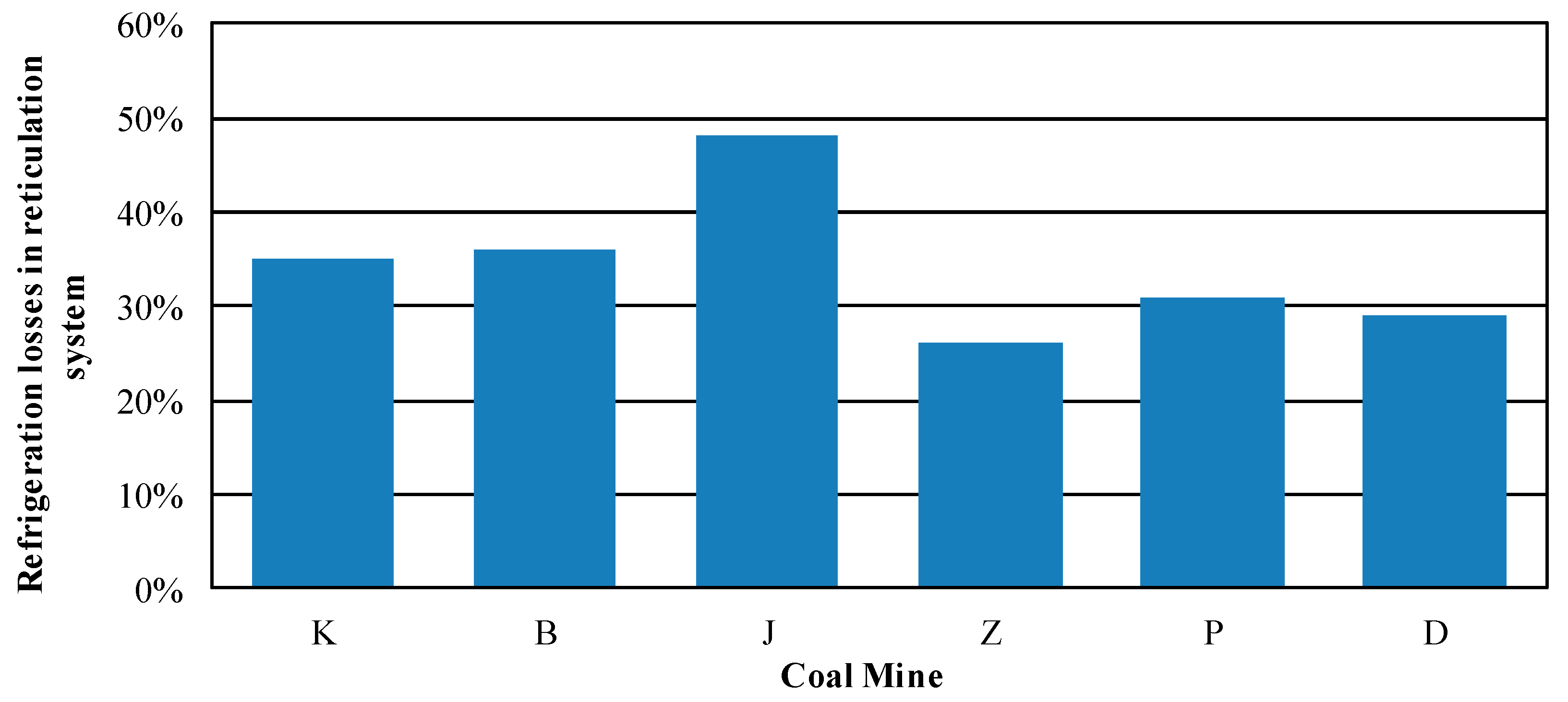
4.3. Thermal Losses in the Piping Systems
Thermal losses in piping systems have a significant influence on the value of cooling power available for heat exchanging in air-cooling coils where it is necessary. The losses were considered at the planning stage and in most mines, they do not exceed the anticipated values. Nevertheless, they are to some extent caused by neglecting the maintenance of the insulation of pipelines supplying ice water to the air coolers. It is an acceptable assumption that the losses of cooling power in the pipelines are not exactly losses because pipelines take in heat from the air supplied to the mining areas, but on the other hand they contribute to the increase in the temperature of the water at the intake of the air-cooling coils, which decreases the efficiency of air cooling. Also, it must be borne in mind that the thermal losses in the piping systems are inversely proportional to the velocity of water flowing through the pipeline. If the velocity of water is low (below 0.5 m/s), a greater amount of heat is transferred from the air to the water than in the case of the higher values of water velocity (above 1.5 m/s). However, increasing the velocity of the flow causes greater losses of water pressure. Therefore, it is vital to rebuild piping networks in mining areas, depending on the required number of air coolers to be connected. Values of hydraulic resistance need to be determined separately whenever the piping network is reconstructed. The working parameters of the circulation pumps need to be checked with reference to the calculated values of the hydraulic resistance.
Figure 5 presents the thermal losses in the piping networks of the particular mines.
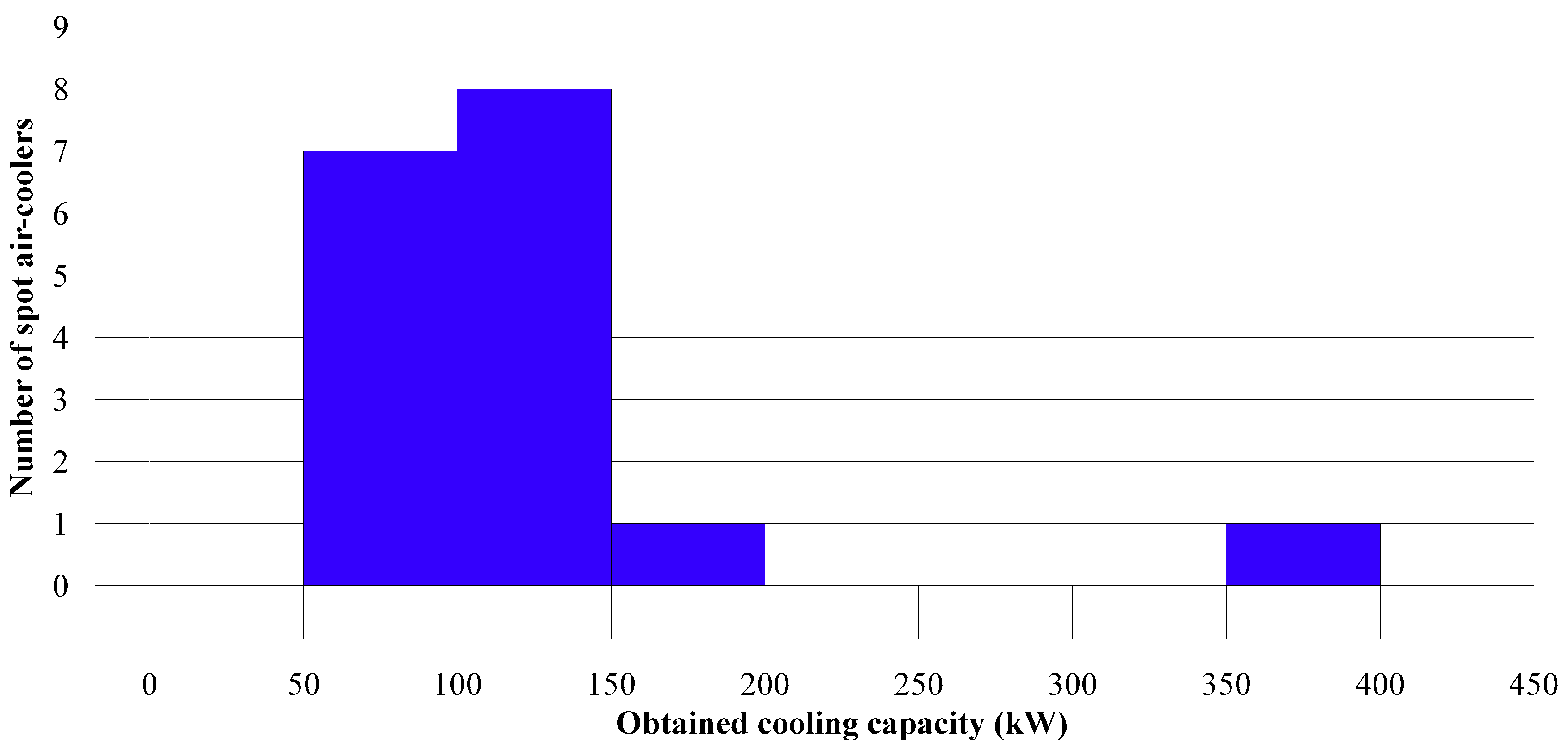
4.4. The Inability of the Spot Air-Coolers to Reach the Required Cooling Capacity.
As heat exchangers of the air-water type, the spot air-coolers under analysis were divided into two groups depending on the cooling power indicated by the manufacturer:
- -
Air-coolers with a rated cooling power from 250 kW to 300 kW—45 items under analysis; and
- -
air-coolers with a rated cooling power from 300 kW to 450 kW—17 items under analysis.
Of all the 62 examined spot air-coolers, only one achieved the required cooling power. In
Figure 6 and
Figure 7, the values of the cooling capacity of the investigated air-coolers are presented in the form of bar charts.
Figure 6 represents devices whose rated power indicated by the manufacturer is from 250 to 350 kW, whereas
Figure 7 represents devices with rated cooling powers from 350 to 450 kW.
The three most important factors for a low cooling capacity of a spot air-cooler can be specified based on the analysis of the results.
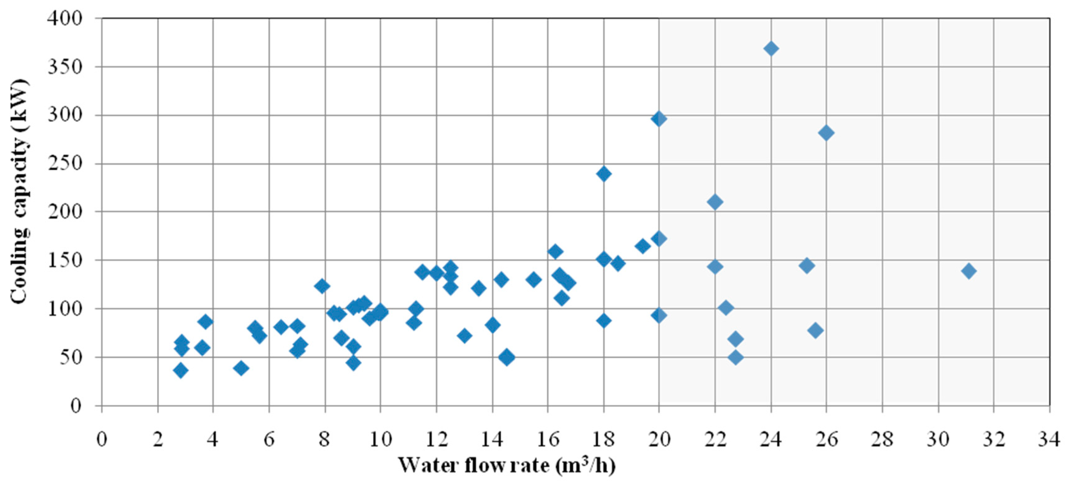
- (1)
The stream of the supplied water is too small. The flow of the water is not monitored, and the distribution of the water is not controlled in the examined installations. The values of the hydraulic resistance are too large because significant pipelines have not been modified during the move of the spot air-coolers.
Figure 7 demonstrates the relationship between the cooling capacity and the water flow rate within the investigated spot air-coolers.
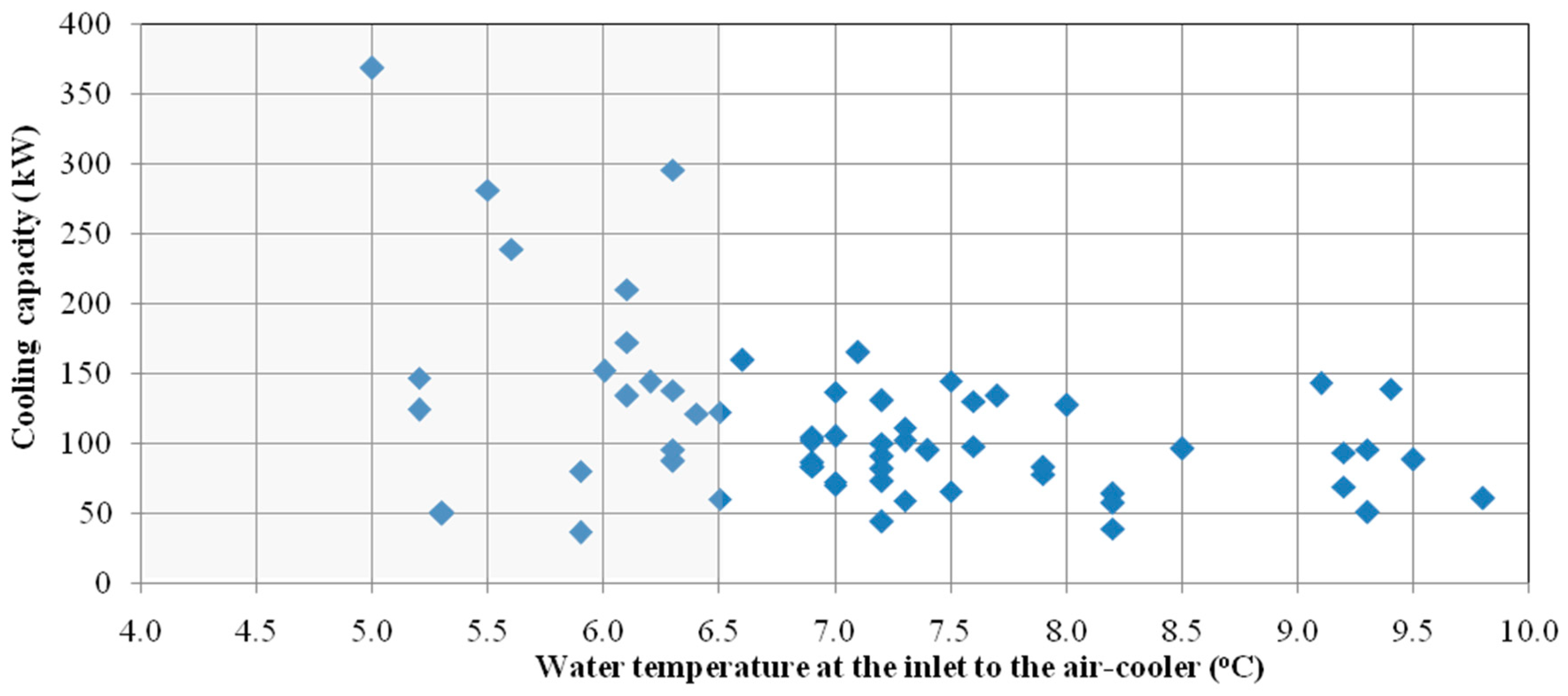
- (2)
The temperature of the supplied water is too high.
Figure 8 demonstrates the relationship between the cooling capacity and the water temperature within the investigated spot air-coolers.
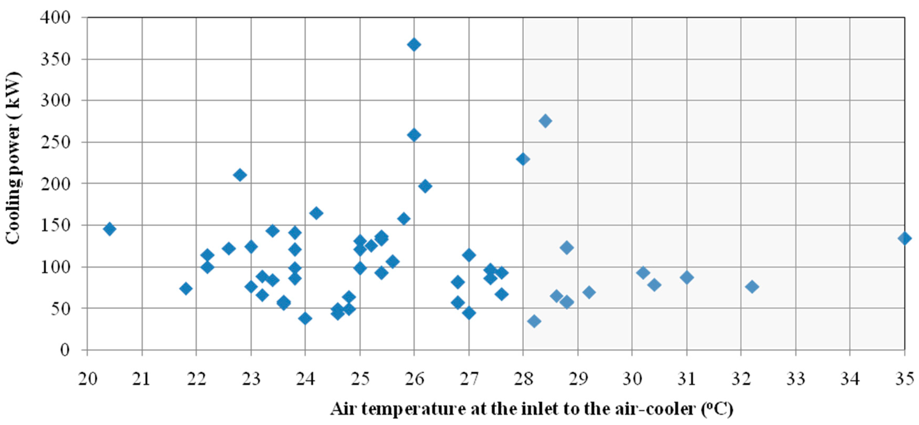
- (3)
The temperature of the air in the gate roads where the spot air-coolers are installed is too low. Air-coolers are not always deployed in the right places. To not move them too often, they are placed at a greater distance from the workplaces. The inlet air temperature is too low, and the coolers cannot reach the rated cooling output.
Figure 9 demonstrates the relationship between the cooling capacity and the air temperature at the inlet to the spot air-coolers.
In
Figure 8,
Figure 9 and
Figure 10, the areas corresponding to the required parameters of the water and air are shaded. For the required cooling capacity to be available, both the water and air at the intake need to have the properties within the thus defined thresholds.
Another significant factor is keeping the tube coils clean. The frequency of cleaning the coils should match the conditions in their place of installation and, in most cases, be greater than indicated by the manufacturer in the operation and maintenance manual of the cooler.
4.5. Problems with Lowering Air Temperature Linked to Humidity
The objectives of using spot air-coolers are both the cooling and dehumidification of mine air. When the humidity of the air is high, as is the case in mine excavations, the latent heat component arises due to the transfer of the water vapour from the moist air and its subsequent condensation on the surface of the cooling coil. The specific heat decreases, so the lowering of the temperature is small.
The air-coolers under analysis often failed to produce a sufficient (i.e., the required by regulations) reduction of air temperature in the gate road, even when such parameters as the temperature and flow rate of the supplied water, the temperature of air in the place of the air-cooler, and the airflow rate approached the values advised by the manufacturer. This failure to reduce air temperature was linked to humidity.
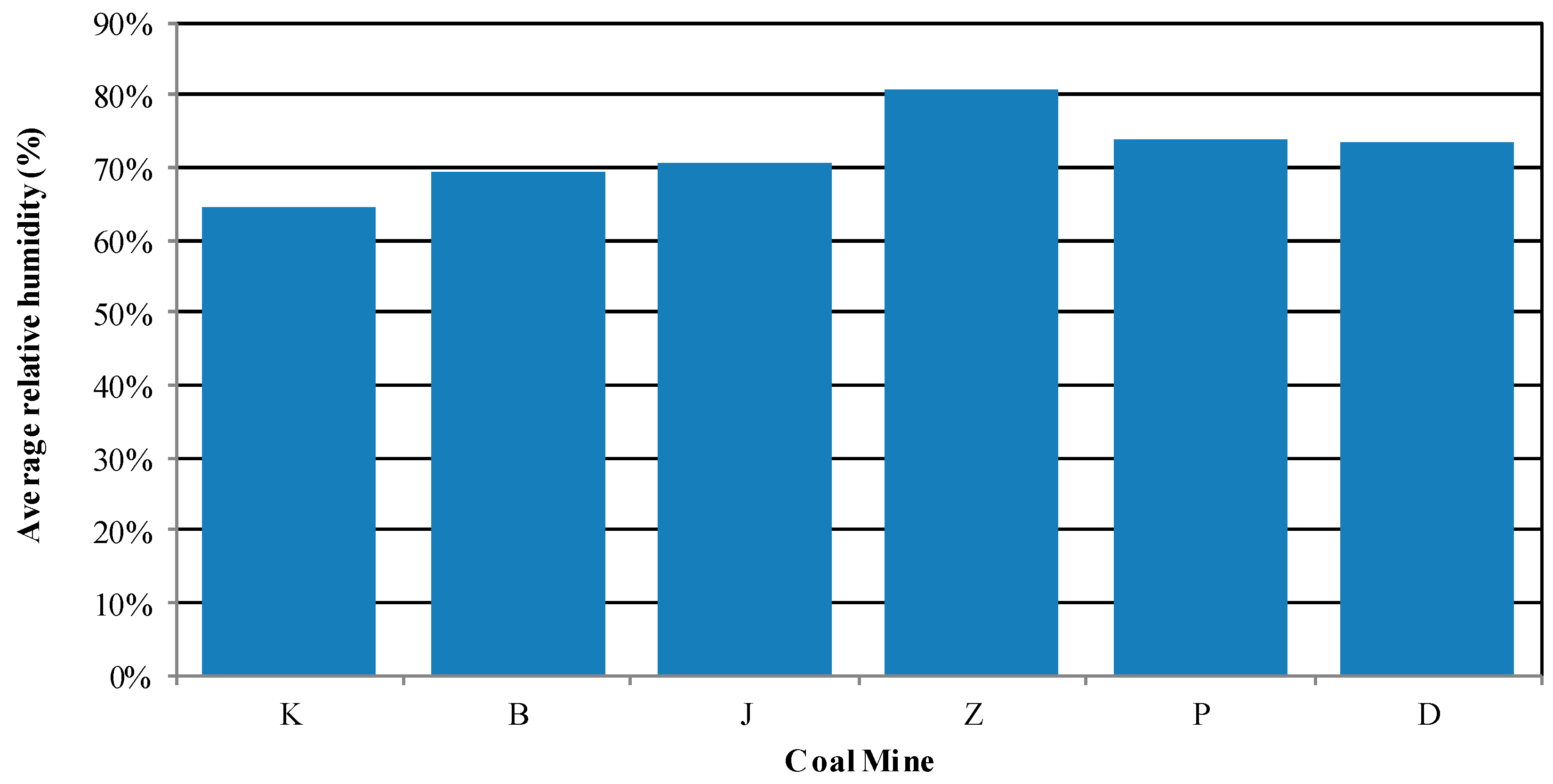
Quite often, the cooling capacity of spot air-coolers indicated by manufacturers refers to conditions in which the relative humidity is below 70%. Therefore, air coolers working in humidity exceeding 80% are bound to not achieve their rated cooling capacity, even when the remaining properties of the air and water are within the permitted limits.
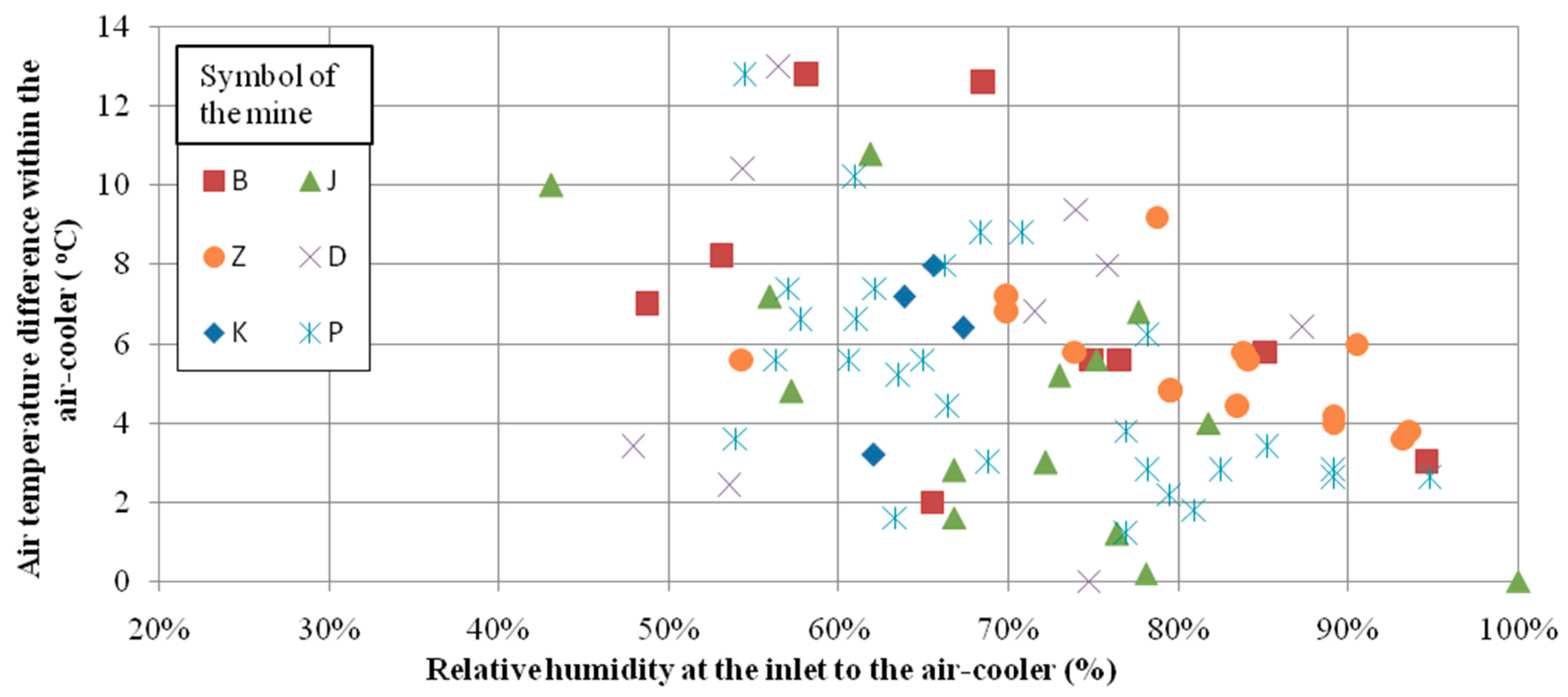
A bar chart of the average relative humidity in places of the air-coolers’ location in particular mines is presented in
Figure 11. High moisture content in the mine air makes it difficult to lower its temperature (see
Figure 12) because a large portion of the cooling power is needed to remove moisture from the air.
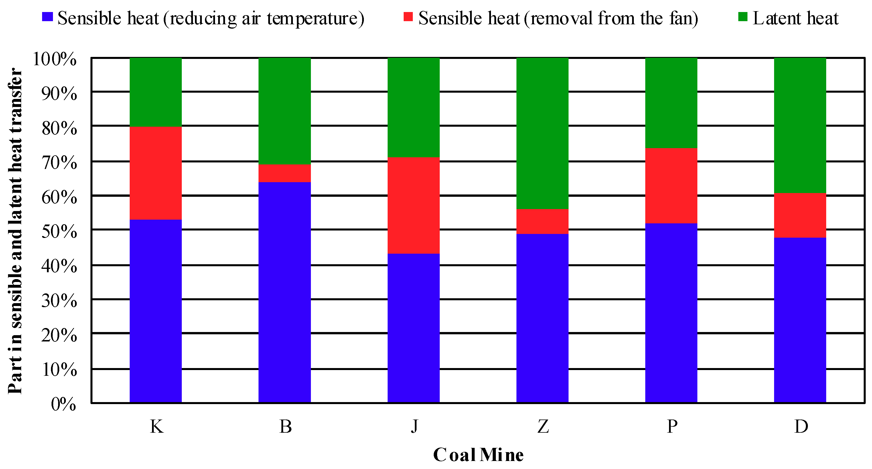
Figure 13 shows what part of cooling power is used in the transfer of sensible and latent heat. In the sensible heat stream, a part of the heat gain originated from the fan of the air-cooler was separated.
Because of the high humidity of the air in the mines under investigation, it is reasonable to reduce excessive humidification of the air in the mining areas (by removing the pools of water in the mine excavations).
Mines should take actions to improve the utilization of cooling power. Nevertheless, insufficient cooling power will be a challenge in several mines, caused by the extent of mining activity in the areas where the virgin rock temperature is high.
5. Conclusions
In Polish underground mines, cooling devices operating directly or indirectly are used. These devices are connected in “group” and “central” cooling systems. Implementing “group” and “central’ air conditioning systems is economically feasible when considerable cooling power is required in various areas of the mine and it is not possible to transfer the condensation heat to the local currents of return air.
A study conducted in six hard-coal mines revealed that despite implementing group and central air conditioning systems, the permitted value of 28 °C of air temperature was exceeded. Apart from other considerations, the efficiency of spot air-coolers depends on their construction and on maintaining the cleanliness of the heat exchange surfaces. However, the root cause of obtaining low cooling parameters is the impossibility of installing air-coolers in places where air temperatures are the highest and the unsatisfactory properties of the supplied water: Low flow rate and excessive temperature.
It is recommended that spot air-coolers be moved to places with the highest air temperatures along with the progress of working faces. Reinstalling the coolers might necessitate modifications of the pipeline network of the cooling system, regulating the distribution of the chilled water. The working parameters of the circulation pumps should be checked and adjusted to conform with the planned modifications of the piping.
In the mining plants, the properties of the water in the pipeline network are controlled to a limited extent, which excludes the possibility of regulating the distribution of chilled water continuously. The parameters of the chilled water in the “group” and “central” cooling systems need to be monitored in accordance with the principles of designing air cooling systems. Information about the current values of water flow rate and temperature is indispensable. Monitoring these parameters enables informed decisions to regulate water distribution, to reinstall spot air-coolers, or to modify the course of common mains.
These factors may be treated on equal terms with key performance indicators (KPIs), which can be used to monitor the performance of cooling system components and provide managers with high-level indicators on which decisions can be based.


