Article

The Interaction Stability Analysis of a Multi-Inverter System Containing Different Types of Inverters

1
State Grid Henan Electric Power Research Institute, Zhengzhou 450052, China
2
State Key Laboratory of Power Transmission Equipment & System Security and New Technology, Chongqing University, Chongqing 400044, China
3
School of Electrical Engineering & Automation, Henan Polytechnic University, Jiaozuo 454003, China
*
Author to whom correspondence should be addressed.
Energies 2018, 11(9), 2244; https://doi.org/10.3390/en11092244
Submission received: 19 July 2018 / Revised: 19 August 2018 / Accepted: 22 August 2018 / Published: 27 August 2018
(This article belongs to the Section I: Energy Fundamentals and Conversion)

Abstract

:
The existing stability investigations of the system containing different types of inverters are insufficient. The paper aims to reveal the more universal interaction stability mechanism of the system containing different types of inverters. Firstly, the multi-inverter system is decomposed into an admittance network (AN) and excitation sources. Then, the interaction between two different inverters, as well as the interaction between the inverter and the power grid, are analyzed by the root locus method. This reveals that the stability of the interaction between the inverter and the power grid is exclusively determined by AN. However, the stability of the interaction between different inverters not only depends on AN but also relies on whether the two inverters have common right-half plane (RHP) poles. To make the multi-inverter system stable, the following two criteria must be satisfied: (a) AN is stable and (b) any two different inverters do not have the same RHP poles. If criterion (a) is not satisfied, the harmonic resonance will arise in all currents. Resonant harmonics will only circulate among partial inverters and will not inject into the power grid if criterion (a) is satisfied but criterion (b) is not satisfied. Theoretical analysis is validated by simulation and experiment results.

1. Introduction

In recent years, an increasing quantity of voltage-source inverters has been connected to power grid as renewable energy expands [1,2]. Especially, multi-parallel inverter system have been widely used to expand the power station capacity, such as large-scale PV plants and wind farms [3,4,5]. In these power stations, plenty of inverters are connected to the point of common coupling (PCC). The interaction effect between inverters and the power grid may aggravate the system stability as the quantity of inverters connected to the PCC rises [6,7,8]. On the other hand, different inverters are coupled due to grid impedance, which thereby may also trigger harmonic resonance [9].
A large amount of work has been done on the stability investigation of the single-inverter, grid-connected system in a weak grid [10,11,12,13,14,15]. For the single-inverter, grid-connected system, it is a single-input, single-output (SISO) system, and the grid impedance can be viewed as part of the filter. Therefore, the influence of grid impedance on system stability can be readily uncovered by the impedance-based method or the classic control theory [13,16]. However, for the multi-inverter, grid-connected system, it belongs to the multiple-input, multiple-output (MIMO) system, in which all inverters are coupled through grid impedance, which cannot be viewed as part of the filter directly. Thereby, the stability analysis becomes complicated.
To clarify the stability and reveal the harmonic resonance mechanism of the multi-inverter system, some methods for simplifying the complex system have been developed recently. The earlier proposal [17] observed the harmonic interaction in many distributed power inverters and attempted to explore the resonance mechanism through a simplified passive circuit model. However, the model is too simple to exactly display the resonance mechanism of the real complex system. Based on an ideal condition in which all the reference currents and all the inverters are equal dynamically in the system, the authors of [18] deduced that for a PV plant consisting of N-paralleled inverters, the equivalent grid series impedance seen by each inverter becomes N times the actual grid impedance. Then, the MIMO system can be simplified as an SISO system. However, in a renewable energy system the reference current of each inverter is usually controlled independently by the outer power loop in practice. So, the applicability of the model and the conclusion for the practical system is restricted by the ideal hypothesis. Given the shortcoming of the ideal model, the authors of [18] also established a more general matrix transfer function from the multiple inputs to the multiple outputs only based on the assumption that all inverters are equal. The characteristic polynomials reflecting internal stability and external stability are extracted from the transfer function. A similar transfer function matrix from the inputs to the outputs is also deduced in [19] on the basis of the Norton model. Then, the potential resonance in the system is divided into the internal resonance, external resonance, and series resonance. To search for a simple method for evaluating the system stability, the authors of [20] extracted a stability-determined loop gain from the current model and proposed a stability analysis method for two identical paralleled rectifiers. Though the authors of [18,19,20] have taken the diversity of inverters into consideration when modeling the system, to avoid the complicated stability analysis they viewed all inverters as equal when analyzing the system stability.
Recently, the authors of [21,22,23] developed an impressive stability analysis method. It divided the inverter current of the multi-inverter system into two parts. Grid impedance only exists in one part of the currents. It views the part containing grid impedance as the interaction between the inverter and the power grid, and considers the other part as the interaction among different inverters. This method reveals the system resonance mechanism explicitly through two equivalent SISO systems. However, this analysis method is based on the system in which all inverters are equal. So, it cannot be suitable for the system containing different types of inverters.
In fact, the multi-inverter system may be constructed in stages, and different types of inverters may be used in different stages [24]. Additionally, since inverter parameters may drift with environmental variation, inverters, even with the same specification and of the same type, may differ. Thus, the differences between different inverters should be taken into account, and it is necessary to investigate the stability and resonance mechanism of the inverter-parallel system consisting of multiple types of inverters. Till now, little research has focused on the system containing different types of inverters. Based on the impedance-based criterion, the authors of [25] try to reveal the interaction resonance mechanism using the traversing method, which will be quite complicated if the system contains plenty of inverters. The authors of [24] investigate the system’s stability by root locus based on obtaining the inverter current directly from the system containing polytype inverters. However, they do not clarify the harmonic resonance mechanism of the interaction between different types of inverters. The authors of [26] try to reveal harmonic resonance with the root locus method based on the system only containing two inverters. However, they do not give a detailed proof for the system containing more than three inverters.
As mentioned ahead, the interaction stability mechanism in the system containing different types of inverters has not been revealed sufficiently. So, the paper is aimed at revealing the interaction stability mechanism of the general multi-inverter system in which inverters may have different control structures. Additionally, the salient contributions are summarized as follows: (1) The interaction resonant mechanism between different types of inverters, as well as between the inverter and the power grid, is revealed for the system containing different types of inverters and (2) A stability analysis method for the multi-inverter system containing multiple types of inverters is proposed.
The rest of the paper has been divided into six parts. Section 2 established the model of the system containing multiple types of inverters. In Section 3, both the interactions between different inverters and the interaction between the inverter and the power grid are analyzed through a set of inverters that have some common RHP poles. In Section 4, a generally used stability criteria for the multi-inverter system is proposed. Section 5 presents five detailed systems to illustrate the application of the proposed stability criterion. In Section 6, simulation and experiment verifications are implemented. Section 7 draws the conclusion.

2. Multi-Inverter System Model

Figure 1 shows the equivalent circuit of a grid-connected parallel-inverter system in which multiple inverters are connected to the power grid through PCC. In the system, LCL-filtered inverters are used to attenuate high-frequency switch harmonics. L1 is the inverter-side filter inductor. L2 is the grid-side filter inductor. C is the filter capacitor. udc is the dc-link voltage. Power grid is equivalent to an ideal voltage source ug in series with a grid impedance Zg. is is the inverter current, and ig is the grid-connected current. ic is filter capacitor current, and up is the PCC voltage. Three different types of inverters are taken as examples in the paper, and their control structures are drawn as Figure 2. Figure 2a shows the dual-loop control structure with capacitor-current-feedback active damping. Figure 2b presents the single-loop control structure with grid-side current feedback or with inverter-side current feedback. According to the authors of [27,28,29,30], the mathematic model in s-domain can be obtained as Figure 3. In the above models, Gc is the current controller, and Gd is the delay transfer function due to the digital control. Gd is given by Equation (1), in which Ts is the sampling period [18,31]. ir is the reference current, and kpwm is the transfer function of the PWM modulator (approximate to udc/2). In the dual-loop control structure, ic is fed back to the current controller to damp the natural resonance of LCL filter.
G d ( s ) = 1 T s   1 e T s s s e T s s
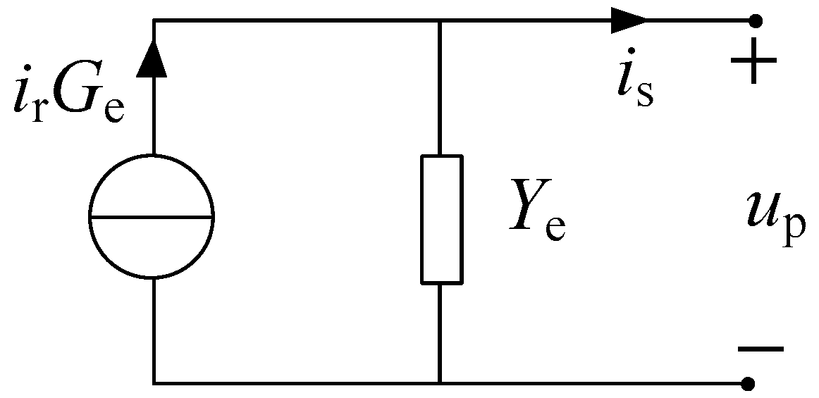
The output current of each type of inverter can be derived as Equation (2) according to Figure 3. Ge is the current transfer function from ir to is. Ye is the transfer function from up to is, and it can be considered as the inverter equivalent output admittance. Since Ge and Ye are derived from the same system, they have the same denominator. For simplification, we have rewritten the simplest forms of Ge and Ye as Equations (3) and (4), in which D is the characteristic polynomial of the inverter. There is no common factor both between W and D and between E and D. Additionally, the inverter can be modeled as Figure 4 according to Equation (2) [4,9,19,20].
i s = G e i r Y e u p  
in which G e = i s i r | u p = 0 , Y e = i s u p | i r = 0 .
G e = W D  
Y e = E D  
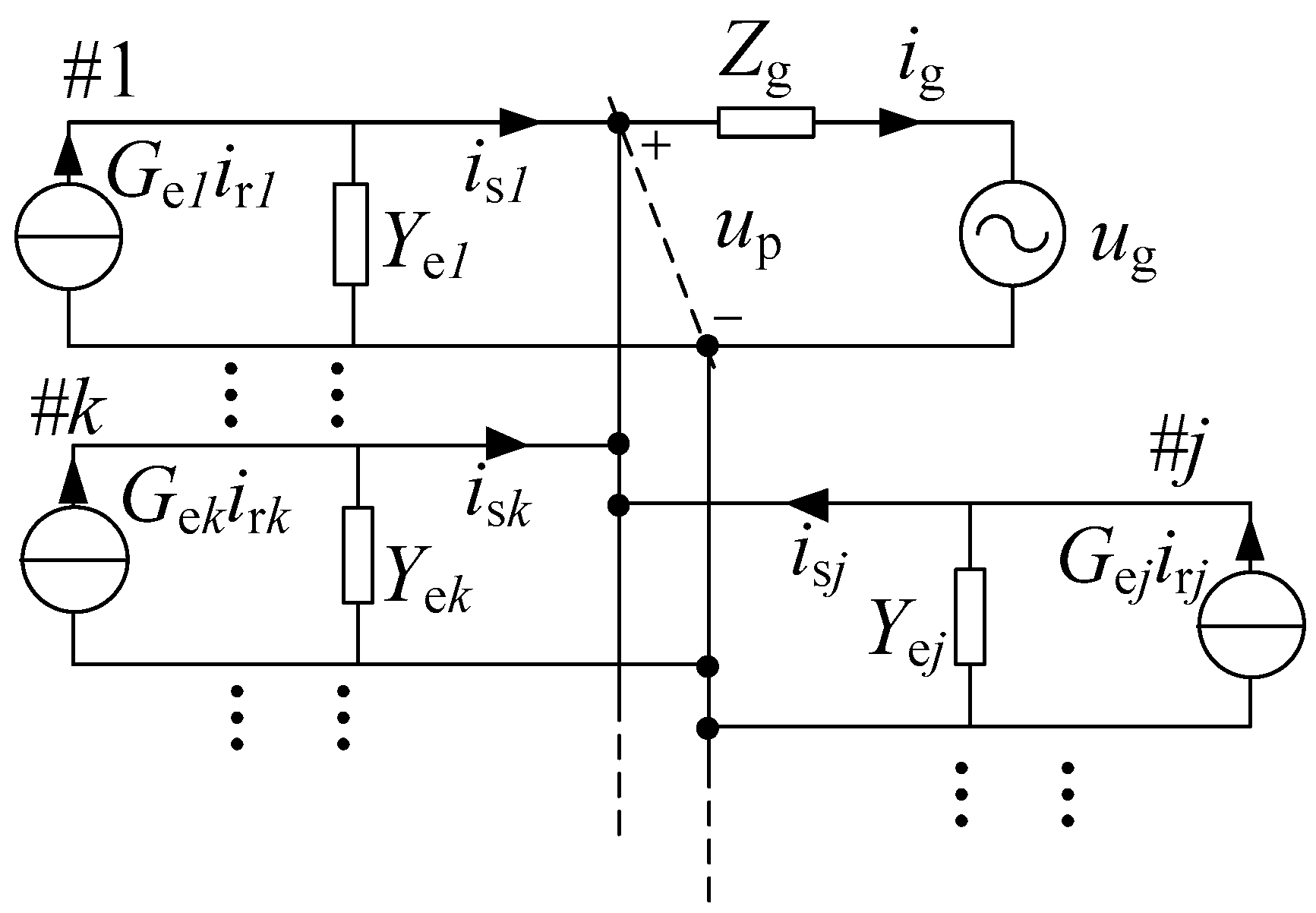
Taking the system containing m inverters as example, the system Norton model can be derived as Figure 5 by replacing each inverter with its corresponding Norton model. In Figure 5, the italic subscript denotes the inverter number. Taking #k inverter as example, its equivalent admittances are Yek, and its closed-loop current transfer function is Gek, in which Yek = Wk/Dk and Gek = Ek/Dk. Additionally, irk is its reference current, and isk is its output current.
When all the excitation sources are set as zero, the multi-port AN can be obtained as in Figure 6. When one current source is connected to AN, the current will flow into every admittance. The transfer function from the current source to the response current both on the #t inverter and the power grid can be obtained as Equations (5) and (6), respectively. Both F and Ht (t ∈ {1, 2, …, m}) reflect the characteristic of AN. Evidently, F and Ht have the same stability for any t ∈ {1, 2, …, m } because of their identical poles. If they contain no RHP poles, AN will be stable and will not amplify harmonics in the current source. If AN is not stable, both F and Ht will contain RHP poles, and harmonics in the current source will be amplified by AN.
H t = Y e t   Y g + j = 1 m Y e j
F = Y g   Y g + j = 1 m Y e j
in which Yg = 1/Zg is the corresponding admittance and t ∈ {1, 2, …, m }.

3. Methodology

3.1. The Set of Inverters with Some Common RHP Poles

To analyze the stability of interactions in the multi-inverter system, firstly we define an unstable inverter set, and we mark the set as Φ-set. All the inverters whose current closed-loop transfer functions or admittances have some common RHP poles constitute a Φ-set. That is to say, all inverters belonging to the same Φ-set have some same RHP poles. For an unstable inverter, it can be a member of a Φ-set, belong to several Φ-sets, or not attach to any Φ-set. According to the definition, if some inverters belong to a Φ-set, their characteristic polynomials, namely, Dk k ∈ {1, 2, …, m }, must have a common unstable factor that is made up of their common RHP poles. For simplification, the common unstable factor is marked as V.
For any k ∈ {1, 2, …, m }, substituting Yek = Wk/Dk into Equation (5) yields Equation (7). Assuming that there are total nx inverters belonging to Φx-set, the common factor V n x 1 can be extracted from the denominator, and Hk can be further written as Equation (8), in which L is the rest part of the denominator. Then, for any tk, HkGet can be obtained as Equation (9).
H k = Z g E k i = 1 , i k   m D i i = 1 m D i + Z g i = 1 m ( E i j = 1 , j i m D j )
H k = Z g E k i = 1 , i k   m D i V n x 1 L
in which L = i = 1 m D i + Z g i = 1 m ( E i j = 1 , j i m D j ) V n x 1 .
H k G e t   = Z g E k i = 1 , i k m D i V n x 1 L W t D t = Z g E k W t i = 1 , i k , i t m D i V n x 1 L
Situation A: both #k inverter and #t inverter belong to Φx-set.
In this situation, the factor V n x 2 can be extracted from i = 1 , i k , i t m D i . Then, HkGet can be rewritten as Equation (10) after offsetting the common factor V n x 1 from the denominator and the numerator. It is evident from Equation (10) that the numerator does not contain factor V, but the denominator still contains the unstable factor V. Therefore, the transfer function HkGet is unstable. Similarly, in this situation HtGek is also unstable.
H k G e t   = Z g E k W t S 1 V L
in which S 1 = i = 1 , i k , i t m D i V n x 2 .
Situation B: #k inverter does not belong to Φx-set, but #t inverter belongs to Φx-set.
In this situation, the factor V n x 1 can be extracted from the numerator of Equation (7) if the factor Dt is kept, and V n x 1 can be also extracted from i = 1 , i k , i t m D i in Equation (9). Then, Hk and HkGet can be rewritten as Equations (11) and (12), respectively, by offsetting the same unstable factor V n x 1 from the corresponding denominator and numerator. Comparing Equations (11) and (12), it can be found that their only difference lies in Dt and Wt. Since Dt does not influence unstable poles in L, Hk and HkGet will have the same stability if Wt also does not contain any common RHP poles with L. If Wt has some unstable factors with L, those unstable factors will also belong to EkS2. Then, Equations (11) and (12) will still have the same stability after offsetting those common unstable factors both in EkS2 and L. That is to say, Hk and HkGet will always have the same stability regardless of whether Wt has common unstable poles with L.
Accordingly, if #t inverter also belongs to other Φ-sets except Φx-set, the corresponding unstable factors in S2 can be offset with those in L by the same method mentioned above. After all the common unstable factors in S2 and L are offset, the polynomial L will have no unstable factors that can be offset by Dt. That is to say, Dt will not influence RHP poles in the denominator of Equation (11). Therefore, HkGet has the same stability with Hk.
Likewise, with the same method, it can be proved that HtGek and Ht have the same stability. In conclusion, for this situation the stability of both HkGet and HtGek is determined by AN.
H k = Z g E k D t i = 1 , i k , i t   m D i V n x 1 L = Z g E k D t S 2 L
H k G e t   = Z g E k W t i = 1 , i k , i t m D i V n x 1 L = Z g E k W t S 2 L
in which S 2 = i = 1 , i k , i t m D i V n x 1 .
Situation C: both #t inverter and #k inverter do not belong to any Φ-set.
In this situation, Hk and HkGet can be written as Equations (13) and (14), respectively. The only difference is between Dt and Wt. With the same method in Situation B, it can be ensured that Hk and HkGet always have the same stability no matter whether Wt and L have the same unstable poles. Namely, in this situation the stability both of HtGek and HkGet is determined by AN.
H k = Z g D t E k i = 1 , i k , i t   m D i i = 1 m D i + Z g i = 1 m ( E i j = 1 , j i m D j )
H k G e t   = Z g W t E k i = 1 , i k , i t m D i i = 1 m D i + Z g i = 1 m ( E i j = 1 , j i m D j )

3.2. Current of the Interaction between Inverter and Power Grid

Based on the Norton model, the net current injecting into power grid from #t inverter can be deduced as Equation (15) according to superposition theorem. It reflects the interaction effect between the #t inverter and the power grid. On the right of the equation, the first part is the response current in the grid admittance when the current source of the #t inverter works alone. The second part denotes the response current in the #t inverter admittance when the power grid voltage works alone.
i g t   = F G e t i r t H t Y g u g
Since Yg has no RHP poles, the stability of HtYg only relies on Ht, i.e., its stability is determined by AN. F can be expressed as Equation (16) by substituting Equation (4) into Equation (6). Then, FGet is derived as Equation (17) by combining Equations (3) and (16). It can be noticed that the only difference between FGet and F lies in Dt and Wt. Then, by adopting the same method in Situation B, it can be concluded that for any t ∈ {1, 2, …, m } the stability of FGet is decided by AN. Therefore, the stability of the net current injecting into the power grid from the inverter only relies on AN. If AN is stable, the interaction between the power grid and the inverter is stable, and vice versa.
F = D t i = 1 , i t   m D i i = 1 m D i + Z g i = 1 m ( E i j = 1 , j i m D j )
F G e t   = i = 1 m D i i = 1 m D i + Z g i = 1 m ( E i j = 1 , j i m D j ) W t D t = W t i = 1 , i t m D i i = 1 m D i + Z g i = 1 m ( E i j = 1 , j i m D j )

3.3. Current of the Interaction between Different Inverters

In terms of the system Norton model, the net current injecting into #k inverter from #t inverter is deduced as Equation (18). It presents the interaction effect between #k inverter and #t inverter. On the right of the equation, the first part is the response current in the #k inverter admittance when the current source of the #t inverter is connected to AN alone, and the second part is the response current in the #t inverter admittance when the current source of the #k inverter works alone.
i t k   = H k G e t i r t H t G e k i r k
According to Section 3, both HtGek and HkGet will be unstable if #t inverter and #k inverter have some same RHP poles. If #t inverter and #k inverter do not share any RHP poles, the stabilities both of HtGek and HkGet are determined by AN. Then, it can be concluded that the interaction between different inverters will be unstable if the corresponding two inverters have some of the same RHP poles, and it will depend on AN if the corresponding two inverters do not have any common RHP poles.
Specially, if #k inverter and #t inverter are identical, i.e., Hk = Ht and Gek = Get, their interaction current can be simplified as Equation (19). Further, if the reference currents of the two inverters are equal, their interaction current will be zero. This is just the ideal case reported by the authors of [18]. However, this case is too ideal to appear in practice. Accordingly, it will be neglected in the paper.
i t k   = H k G e k ( i r t i r k ) = 1 2 ( G e k F G e k j = 1 , j k , j t m H j G e k ) ( i r t i r k )
Another ideal case is that the power grid is ideal, namely, Zg = 0. Then, Ht = 0 and F = 1, which results in the fact that all inverters are connected to the ideal power grid directly and there is no interaction between any two different inverters. However, the grid impedance always exists in practice. Therefore, the interaction effect between different inverters always exists, and its stability is determined both by AN and the inverter itself.
To sum up, if both #k inverter and #t inverter belong to the same Φ-set, both HtGek and HkGet are unstable. As a result, the interaction current between two inverters, given by Equation (18), will be unstable. If #k inverter and #t inverter do not belong to the same Φ-set, stabilities both of HtGek and HkGet only depend on AN. Then, the stability of the interaction current between the two inverters will only depend on AN. Specially, for two identical inverters, if they have RHP poles they naturally belong to the same Φ-set, illustrating that their interaction current is unstable. If they are stable, the stability of their interaction current depends on AN.

4. Stability Criterion of Multi-Inverter System

Taking #t inverter, for example, its output current can be derived as Equation (20) by summing all the net current flowing out from the inverter. On the right of Equation (20), the first part denotes the interaction current between the inverter and the power grid, and the second part denotes the interaction current between the #t inverter and the other inverters. As analyzed above, the stability of the first part is determined by AN. For the second part, if #t inverter belongs to some a Φ-set it will be unstable, and if #t inverter does not attach to any Φ-set, its stability will be depended on AN. Therefore, the stability of the inverter current relies both on AN and on whether the inverter has common RHP poles with other inverters. Either the unstable AN or the common RHP poles with other inverters will trigger instabilities of the inverter current. Only when AN is stable and the inverter has no common RHP poles with other inverters will the inverter current be stable.
i s t   = F G e t i r t H t Y g u g interaction   between   # t   inverter   and   the   power   grid + j = 1 , j t m [ H j G e t i r t H t G e j i r j ] interaction   between   # t   inverter   and   the   other   inverters
According to superposition principle, the grid current is the sum of all the net currents injecting into the power grid and it can be obtained as Equation (21). On the right of Equation (21), the first part denotes the current injecting into the power grid from all inverters, and the second part is the current flowing out from the power grid to all inverters. According to the analysis in Section 3, the stabilities of both parts only depend on AN. So, the stability of the grid current only relies on AN. Whatever the other conditions are, the grid current will be stable as long as AN is stable.
i g = j = 1   m F G e j i r j u g n = 1 m H n Y g
Only when all inverter currents and the grid current are stable will be the system stable. Then, the stability criteria can be summarized as:
(a)
Admittance network is stable.
(b)
Any two different inverters do not have the same RHP poles.
Criterion (a), determining both the grid current stability and the inverter current stability, is predominant in the two criteria. If criterion (a) is not satisfied, all the inverter currents and the grid current will be not stable no matter what other conditions are. In this condition, harmonic resonance will propagate in all the inverter currents and in the grid current.
Criterion (b) only determines the stability of the inverter current. If criterion (a) is satisfied but criterion (b) is not satisfied, the grid current and the currents generated by the inverters that do not belong to any Φ-sets are stable. However, the currents generated by the inverters that belong to some Φ-sets will be unstable. For this condition, harmonic resonance will only arise in those inverters that have some common RHP poles and will never flow into the other inverters or into the power grid.

5. Case Study

Root locus method will be used in the part to illustrate the application of the proposed stability criterion intuitively. Additionally, three types of inverters listed in Table 1 are taken as example. Type-a adopts dual-loop control structure. Type-b adopts single-loop control structure with grid-side current feedback, and type-c adopts single-loop control structure with inverter-side current feedback. Quasi-PR (quasi proportional plus resonant) controller, shown as Equation (22) [14,15,20], is adopted to regulate the inverter current.
G c ( s ) = k p + 2 k r ω i s   s 2 + 2 ω i s + ( ω 0 ) 2
in which kp is the proportional factor, kr is the resonant factor, ωi is the bandwidth factor, and ω0 is the fundamental angular frequency.
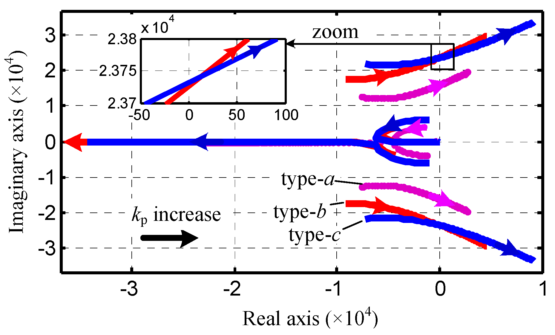
As corresponding kp increases the root loci of Yea, Yeb and Yec are plotted as Figure 7, in which Yea, Yeb, and Yec are inverter admittances of type-a, type-b, and type-c, respectively. Evidently, there is a pair of poles moving to RHP, with kp increasing for all types of inverters. When kp exceeds a certain value, the poles will reach RHP, and the inverter will become unstable. Additionally, it is interesting to find that there exists a pair of intersections for the root loci of type-b inverter and type-c inverter. As seen from the zoom, the intersection poles are located in RHP, indicating that the type-b inverter and the type-c inverter will share a pair of the same RHP poles if kpb and kpc satisfy some conditions. Additionally, the conditions that kpb and kpc have to satisfy for the intersection are calculated as kpb = 0.5303 and kpc = 0.2257.
Based on the above root loci, three systems shown as Table 2 are selected to study different resonance cases. System I contains three different states. Both System II and System III contain one state. Controller parameters for different states are shown as Table 3.
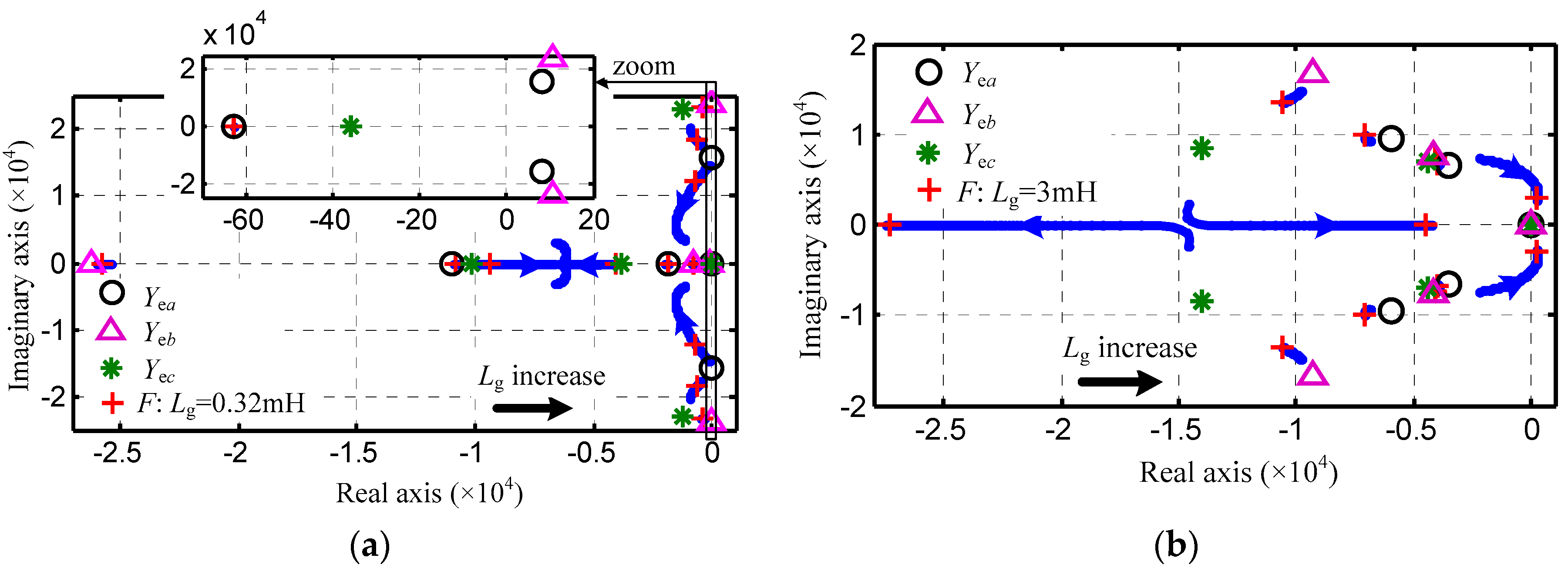
For state-A, pole maps of the three inverters are depicted as Figure 8a, in which F is the transfer function of AN. As can be seen, #1 inverter and #2 inverter have a pair of different RHP poles, and #3 is stable. With grid impedance variation, the root locus of AN is plotted as the blue solid line in Figure 8a. When grid impedance increases to 0.32 mH, the poles are shown as the red plus sign, indicating that AN is stable. In this case, since both criterion (a) and criterion (b) are satisfied, both the grid current and all the inverter currents will be stable.
For state-B, pole maps of the three inverters are drawn as Figure 8b, indicating that the three inverters are all stable. Then, root locus of AN with grid impedance variation is drawn as the blue solid line in Figure 8b. When the grid impedance increases to 3 mH, poles of AN are shown as the red plus sign. As seen, a pair of poles stay in RHP, illustrating that AN is unstable. In this case, since criterion (a) is not satisfied, the grid current and all the inverter currents will be not stable. Harmonic resonance will propagate in all currents.
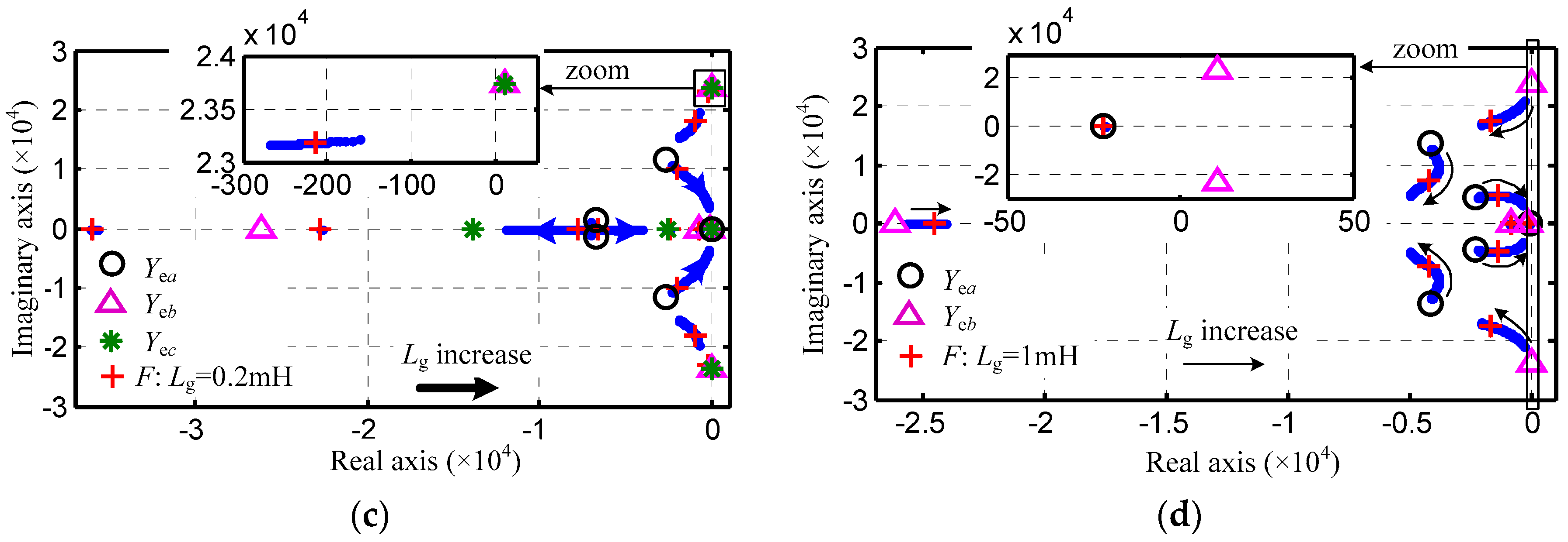
For state-C, pole maps of the three inverters are sketched as in Figure 8c. It can be seen that #2 inverter has a pair of the same RHP poles with the #3 inverter, and #1 inverter contains no RHP poles. The root locus of AN with grid impedance variation is drawn as the blue solid line in Figure 8c. As the grid impedance rises to 0.2 mH, poles of AN are shown as the red plus sign. Evidently, all poles of AN are in LHP, indicating that AN is stable. In this case, criterion (a) is satisfied, but criterion (b) is not satisfied. So, both the #2 inverter current and the #3 inverter current will be not stable, whereas both the grid current and the #1 inverter current will be stable. Harmonic resonance will only circulate between #2 inverter and #3 inverter.
For state-D, pole maps of the two types of inverters are shown as Figure 8d. As seen, type-1 inverter is stable, but type-2 inverter is unstable, indicating that #1 inverter is stable but neither #2 inverter nor #3 inverter is stable. With grid impedance variation, the root locus of AN is shown as the blue solid line in Figure 8d. When grid impedance is 1mH, its poles are shown as the red plus sign, indicating that AN is stable. Therefore, the currents both of the #2 inverter and the #3 inverter will be not stable, but the #1 inverter current, as well as the grid current, will be stable. Similarly, harmonic resonance will only circulate between the #2 inverter and the #3 inverter.
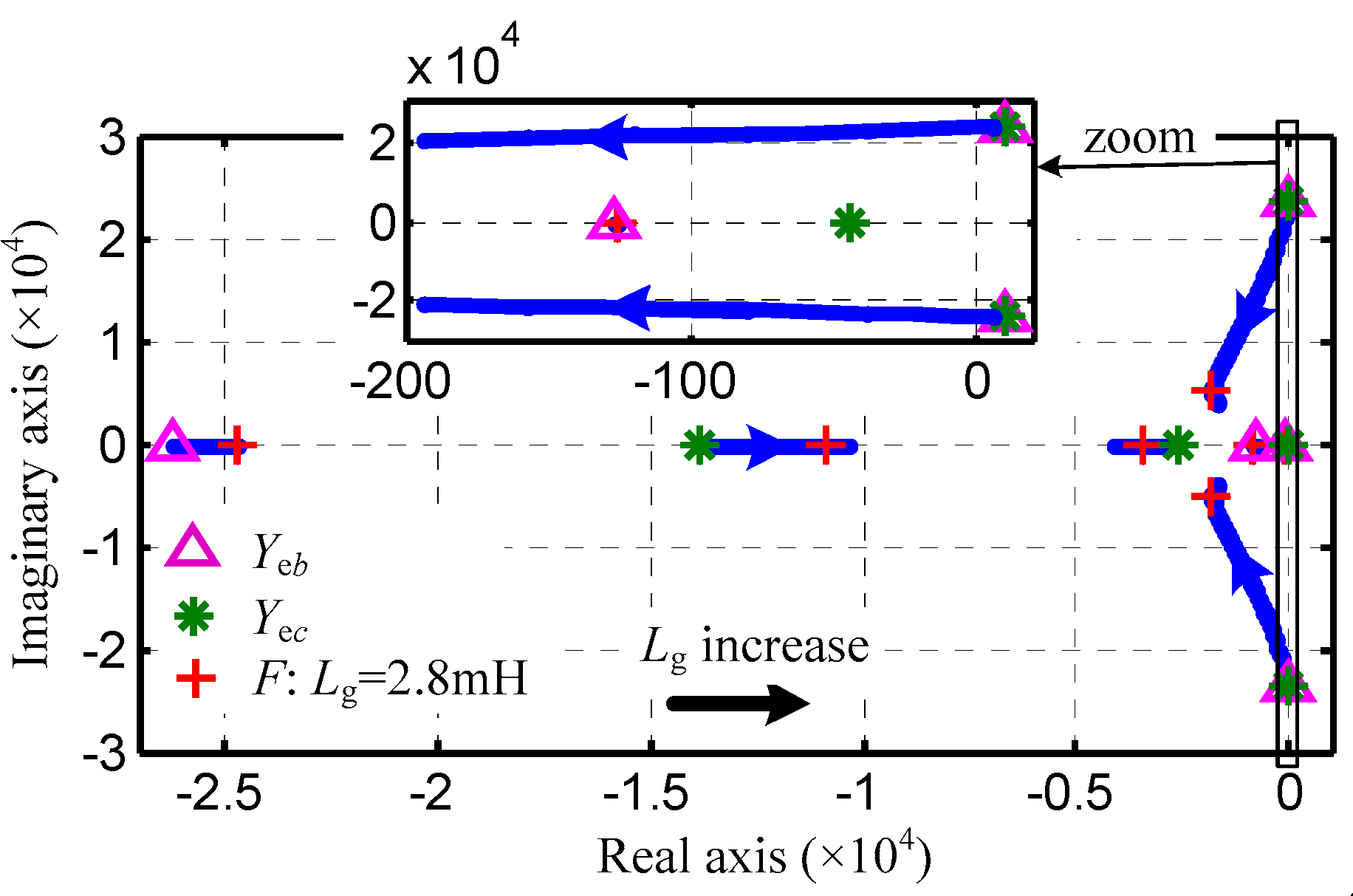
For state-E, pole maps of the two types of inverters are depicted as Figure 9. It is seen that there are pairs of the same RHP poles for the two types of inverters. In Figure 9, the blue solid line is the root locus of AN with grid impedance variation. When Lg increases to 2.8 mH, the poles of AN are marked as the red plus sign, indicating that AN is stable. Therefore, all the inverter currents will be unstable, but the grid current will be stable in the case. Namely, harmonic resonance will only circulate among three inverters but will never flow into power grid.

6. Simulation and Experiment Verification

To verify the proposed stability criterion, both time-domain simulations and experiments are implemented based on the three systems analyzed in Section 6. In time-domain verification, the reference current and the grid impedance for each state are shown as Table 4.

6.1. Simulation Results

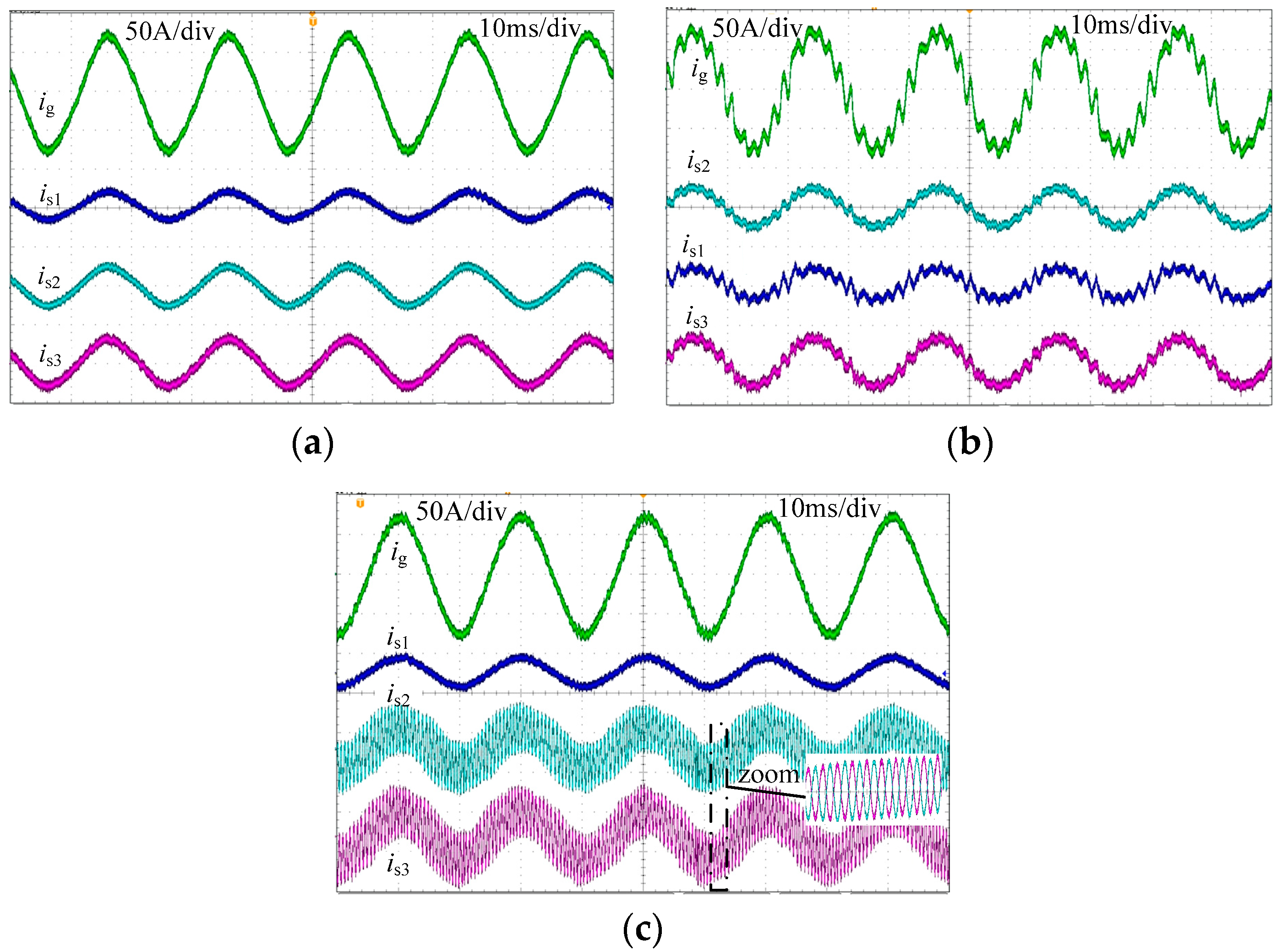
For System I, when it switches to state-B from state-A simulation, results are shown as Figure 10a. Obviously, when the system works in state-A, all current waveforms are smooth, with few harmonics. However, after it switches to state-B, all currents are distorted seriously with plenty of harmonics. When the system switches to state-C from state-A, simulation results are shown as Figure 10b. Evidently, both #2 inverter current and #3 inverter current become unstable after the system switches to state C. However, the grid current and #1 inverter current are always good. Moreover, as seen from the zoom view, the resonant harmonics of the two inverter currents have the same magnitude and the opposite phase. Therefore, they are offset with each other and never flow into the other inverters or into the power grid. For System II, when it works in state-D simulation, waveforms are presented as Figure 10c. Obviously, both the #2 inverter current and the #3 inverter current are distorted with massive harmonics, but both the #1 inverter current and the grid current are smooth, with few harmonics. For System III, when it works in state-E simulation, waveforms are presented as Figure 10d. It can be seen that all inverter currents lose stability, but the grid current is still stable.

6.2. Experiment Results

Experiments are implemented on the test platform containing three single-phase inverters. A 45 kVA regenerative grid simulator is used to simulate the power grid. An inductor is inserted between the PCC and the grid simulator to simulate the grid impedance.
Figure 11a shows experimental results of state-A, in which AN and #3 inverter are stable, but both #1 inverter and #2 inverter contain RHP poles. In addition, their RHP poles are not the same. Obviously, all the inverter currents and the grid current are high-quality, indicating that all the currents are stable.
Figure 11b presents the results of state-A, in which no inverter contains RHP poles but AN is not stable. As seen, plenty of harmonics arise in all inverter currents and the grid current, indicating that all the currents are unstable. Figure 11c shows the experimental current waveforms of state-C, in which both #1 inverter and AN are stable, but the #2 and #3 inverter share a pair of common RHP poles. Evidently, harmonic resonance only propagates in the #2 inverter and #3 inverter, whereas both the grid current and #1 inverter current are smooth with few harmonics. The results verify that the currents both of the #2 and #3 inverter lose stability due to their common RHP poles. Both the #1 inverter current and the grid current are stable, since the #1 inverter does not have any common RHP poles with other inverters, and the AN is stable. The zoom view in Figure 11c shows that the resonant harmonics of the two inverter currents have the same magnitude and the opposite phase. Therefore, they are offset with each other and never flow into the other inverters or into the power grid.
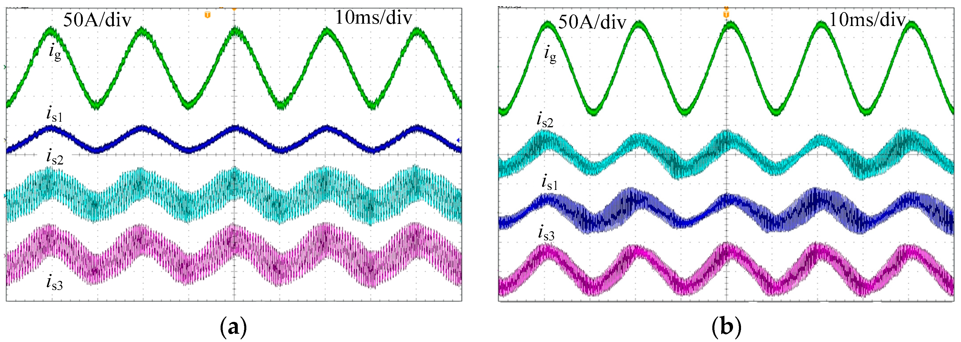
Figure 12a shows the experiment results of state-D, in which #2 and #3 inverter are identical and unstable. It is obvious that the inverter currents both of the #2 and #3 inverter oscillate seriously. However, both the #1 inverter current and the grid current are satisfactory and high-quality. The results coincide with the theoretical analysis that both the #1 inverter current and the grid current are stable, since AN is stable and the #1 inverter contains none of the same RHP poles as other inverters, and the currents of the #2 and #3 inverter are unstable, since they have a pair of the same RHP poles.
Figure 12b shows the results of state-E, in which the three inverters have a pair of the same RHP poles and AN is stable. Manifestly, the harmonic resonance arises in all the three inverter currents but does not inject into the grid current. The results verify that all the inverter currents are unstable, since all the inverters have some same RHP poles, and the grid current is stable, because AN contains no RHP pole.

7. Conclusions

In the paper, the interaction stability mechanism of the multi-inverter system containing different types of inverters is revealed. It reveals that the stability of the interaction between the inverter and the power grid is exclusively determined by AN, whereas the stability of the interaction between two different inverters not only relies on AN but also is dependent on whether or not the two inverters have common RHP poles. The stability criteria for the general multi-inverter system are (a) AN is stable and (b) any two different inverters do not have the same RHP poles. If criterion (a) is not satisfied, all the inverter currents and the grid current will be unstable. If criterion (a) is satisfied but criterion (b) is not, satisfied resonant harmonics will only circulate among partial inverters but will not influence other inverter currents or the grid current.

Author Contributions

Conceptualization, L.Z. and C.Z.; Methodology, B.L.; Validation, M.M. and C.Z.; Formal Analysis, L.Z.; Investigation, B.L.; Writing-Original Draft Preparation, C.Z.; Writing-Review & Editing, Q.L.

Acknowledgments

This work was supported by the project “Research on Detection Key Technologies and Propagation Characteristics of Ultra High Harmonic in Power Electronic Distribution Network”, the National Natural Science Foundation of China (grant number 51477021) and the "111" State Innovation & Talent Recruitment Base under grant 808036.

Conflicts of Interest

The authors declare no conflict of interest.

References

  1. Carrasco, J.M.; Franquelo, L.G.; Bialasiewicz, J.T.; Galvan, E.; PortilloGuisado, R.C.; Prats, M.A.M.; Leon, J.I.; Moreno-Alfonso, N. Power-electronic systems for the grid integration of renewable energy sources: A survey. IEEE Trans. Ind. Electron. 2006, 53, 1002–1016. [Google Scholar] [CrossRef]
  2. Morjaria, M.; Anichkov, D.; Chadliev, V.; Soni, S. A grid-friendly plant: The role of utility-scale photovoltaic plants in grid stability and reliability. IEEE Power Energy Mag. 2014, 12, 87–95. [Google Scholar] [CrossRef]
  3. Blaabjerg, F.; Teodorescu, R.; Liserre, M.; Timbus, A.V. Overview of control and grid synchronization for distributed power generation systems. IEEE Trans. Ind. Electron. 2006, 53, 1398–1409. [Google Scholar] [CrossRef]
  4. Zhou, L.; Zhang, M. Modeling and stability of large-scale PV plants due to grid impedance. In Proceedings of the 39th Annual Conference of the IEEE Industrial Electronics Society, Vienna, Austria, 10–13 November 2013. [Google Scholar]
  5. Francisco, F.D.; Rodriguez-Diaz, E.; Golsorkhi, M.S.; Vasquez, J.C.; Guerrero, J.M. A root-locus design methodology derived from the impedance/admittance stability formulation and its application for LCL grid-connected converters in wind turbines. IEEE Trans. Power Electron. 2017, 32, 8218–8228. [Google Scholar]
  6. Gao, L.; Wang, H.; Huang, Y. Analysis on the interaction of multi grid-connected inverters in distribution network. In Proceedings of the 8th International Power Electronics and Motion Control Conference, Hefei, China, 22–26 May 2016. [Google Scholar]
  7. Wang, H.; Zhang, P.; Su, J.; Zhang, G. Resonant mechanism of multi grid-connected inverters in distribution power systems. In Proceedings of the 2015 IEEE Energy Conversion Congress and Exposition (ECCE), Montreal, QC, Canada, 20–24 September 2015. [Google Scholar]
  8. Juntunen, R.; Korhonen, J.; Musikka, T.; Smirnova, L.; Pyrhönen, O.; Silventoinen, P. Identification of resonances in parallel connected grid inverters with LC- and LCL-filters. In Proceedings of the 2015 IEEE Applied Power Electronics Conference and Exposition (APEC), Charlotte, NC, USA, 15–19 March 2015. [Google Scholar]
  9. Yu, C.; Zhang, X.; Liu, F.; Li, F.; Xu, H.; Cao, R.; Ni, H. Modeling and resonance analysis of multiparallel inverters system under asynchronous carriers conditions. IEEE Trans. Power Electron. 2017, 32, 3192–3205. [Google Scholar] [CrossRef]
  10. Gabe, I.J.; Montagner, V.F.; Pinheiro, H. Design and implementation of a robust current controller for VSI connected to the grid through an LCL filter. IEEE Trans. Power Electron. 2009, 24, 1444–1452. [Google Scholar] [CrossRef]
  11. Lorzadeh, I.; Abyaneh, H.A.; Savaghebi, M.; Bakhshai, A.; Guerrero, J.M. Capacitor current feedback-based active resonance damping strategies for digitally-controlled inductive-capacitive-inductive-filtered grid-connected inverters. Energies 2016, 9, 462. [Google Scholar] [CrossRef] [Green Version]
  12. Li, X.; Lin, H. Stability analysis of grid-connected converters with different implementations of adaptive PR controllers under weak grid conditions. Energies 2018, 11, 2004. [Google Scholar] [CrossRef]
  13. Liserre, M.; Teodorescu, R.; Blaabjerg, F. Stability of photovoltaic and wind turbine grid-connected inverters for a large set of grid impedance values. IEEE Trans. Power Electron. 2006, 21, 263–272. [Google Scholar] [CrossRef]
  14. Pan, D.; Ruan, X.; Bao, C.; Li, W.; Wang, X. Optimized controller design for LCL-type grid-connected inverter to achieve high robustness against grid-impedance variation. IEEE Trans. Ind. Electron. 2015, 62, 1537–1547. [Google Scholar] [CrossRef]
  15. Yang, D.; Ruan, X.; Wu, H. Impedance shaping of the grid-connected inverter with LCL filter to improve its adaptability to the weak grid condition. IEEE Trans. Power Electron. 2014, 29, 5795–5805. [Google Scholar] [CrossRef]
  16. Sun, J. Impedance-based stability criterion for grid-connected inverters. IEEE Trans. Power Electron. 2011, 26, 3075–3078. [Google Scholar] [CrossRef]
  17. Enslin, J.H.R.; Heskes, P.J.M. Harmonic interaction between a large number of distributed power inverters and the distributed network. IEEE Trans. Power Electron. 2004, 19, 1586–1593. [Google Scholar] [CrossRef]
  18. Agorreta, J.L.; Borrega, M.; Lopez, J.; Marroyo, L. Modeling and control of N-paralleled grid-connected inverters with LCL filters coupled due to grid impedance in PV plants. IEEE Trans. Power Electron. 2011, 26, 770–785. [Google Scholar] [CrossRef]
  19. He, J.; Li, Y.; Bosnjak, D.; Harris, B. Investigation and active damping of multiple resonances in a parallel-inverter-based microgrid. IEEE Trans. Power Electron. 2013, 28, 234–246. [Google Scholar] [CrossRef]
  20. Wang, X.; Blaabjerg, F.; Liserre, M.; Chen, Z.; He, J.; Li, Y. An active damper for stabilizing power-electronics-based ac systems. IEEE Trans. Power Electron. 2014, 29, 3318–3329. [Google Scholar] [CrossRef]
  21. Lu, M.; Wang, X.; Blaabjerg, F.; Loh, P.C. An analysis method for harmonic resonance and stability of multi-paralleled LCL-filtered inverters. In Proceedings of the 6th International Symposium on Power Electronics for Distributed Generation Systems (PEDG), Aachen, Germany, 22–25 June 2015. [Google Scholar]
  22. Lu, M.; Wang, X.; Loh, P.C.; Blaabjerg, F. Interaction and aggregated modeling of multiple paralleled inverters with LCL filter. In Proceedings of the 2015 IEEE Energy Conversion Congress and Exposition (ECCE), Montreal, QC, Canada, 20–24 September 2015. [Google Scholar]
  23. Lu, M.; Wang, X.; Loh, P.C.; Blaabjerg, F. Resonance interaction of multiparallel grid-connected inverters with LCL filter. IEEE Trans. Power Electron. 2017, 32, 894–899. [Google Scholar] [CrossRef]
  24. Zheng, C.; Zhou, L.; Guo, K.; Liu, Q.; Xie, B. Stability study of large-scale photovoltaic plant containing polytype inverters. In Proceedings of the International Power Electronics and Motion Control Conference (PEMC), Varna, Bulgaria, 25–28 September 2016. [Google Scholar]
  25. Yoon, C.; Bai, H.; Beres, R.N.; Wang, X.; Bak, C.L.; Blaabjerg, F. Harmonic Stability Assessment for Multiparalleled, Grid-Connected Inverters. IEEE Trans. Sustain. Energy 2016, 7, 1388–1396. [Google Scholar] [CrossRef]
  26. Zheng, C.; Zhou, L.; Li, B.; Liu, J.; Hao, G. Interaction resonance mechanism of the parallel-inverter system containing multiple types of inverters. In Proceedings of the 43rd Annual Conference of the IEEE Industrial Electronics Society, Beijing, China, 29 October–1 November 2017. [Google Scholar]
  27. Pan, D.; Ruan, X.; Wang, X.; Yu, H.; Xing, Z. Analysis and design of current control achemes for LCL-type grid-connected inverter based on a general mathematical model. IEEE Trans. Power Electron. 2017, 32, 4395–4410. [Google Scholar] [CrossRef]
  28. Liberos, M.; González-Medina, R.; Garcerá, G.; Figueres, E. Modelling and control of parallel-connected transformerless inverters for large photovoltaic farms. Energies 2017, 10, 1242. [Google Scholar] [CrossRef]
  29. Sun, J. Small-signal methods for AC distributed power systems—A review. IEEE Trans. Power Electron. 2009, 24, 2545–2554. [Google Scholar]
  30. Yu, Y.; Li, H.; Li, Z.; Zhao, Z. Modeling and analysis of resonance in LCL-type grid-connected inverters under different control schemes. Energies 2017, 10, 104. [Google Scholar] [CrossRef]
  31. Jalili, K.; Bernet, S. Design of LCL filters of active-front-end twolevel voltage-source converters. IEEE Trans. Ind. Electron. 2009, 56, 1674–1689. [Google Scholar] [CrossRef]
Figure 1. Equivalent circuit of the multi-paralleled inverters.
Energies 11 02244 g001
Figure 2. Inverter control structure: (a) dual-loop control structure; (b) single-loop control with grid-side current feedback or with inverter-side current feedback.
Energies 11 02244 g002
Figure 3. Inverter equivalent mathematic model in s-domain: (a) dual-loop control structure; (b) single-loop control with grid-side current feedback; (c) single-loop control with inverter-side current feedback.
Energies 11 02244 g003
Figure 4. Inverter Norton model.
Energies 11 02244 g004
Figure 5. System equivalent Norton model.
Energies 11 02244 g005
Figure 6. Admittance network.
Energies 11 02244 g006
Figure 7. Root loci of the three types of inverters.
Energies 11 02244 g007
Figure 8. Pole maps of inverters and root locus of AN with grid impedance varying: (a) a state-A: pole maps of the three inverters and root locus of AN with grid impedance varying; (b) state-B: pole maps of three inverters and root locus of AN with grid impedance varying; (c) state-C: pole maps of three inverters and root locus of AN with grid impedance varying; (d) state-D: pole maps of the two types of inverters and root locus of AN with grid impedance varying.
Energies 11 02244 g008aEnergies 11 02244 g008b
Figure 9. System E: pole maps of the two types of inverters and root locus of AN with grid impedance varying.
Energies 11 02244 g009
Figure 10. Simulation results: (a) System I switches to state-B from state-A; (b) System I switches to state-C from state-A; (c) System II works in state-D; (d) System III works in state-E.
Energies 11 02244 g010
Figure 11. Experimental current waveforms of System I: (a) stat-A; (b) stat-B; (c) stat-C.
Energies 11 02244 g011
Figure 12. Experimental current waveforms of System II and System III: (a) stat-D; (b) stat-E.
Energies 11 02244 g012
Table 1. System main parameters.
ItemsType-aType-bType-c
P6 kW8 kW10 kW
ug220 V220 V220 V
udc330 V330 V330 V
L14.5 mH2.8 mH2 mH
Cf5 uF3.65 uF5 μF
L20.9 mH0.56 mH0.4 mH
Table 2. System construction.
Items#1#2#3
System Itype-atype-btype-c
System IItype-atype-btype-b
System IIItype-btype-btype-c
Table 3. Proportional coefficient kp of the current controller for different states.
SystemState#1#2#3
System Istate-A0.3880.53030.181
state-B0.140.110.08
state-C0.20.53030.2257
System IIstate-D0.20.53030.5303
System IIIstate-E0.53030.53030.2257
Table 4. Reference current and grid impedance for each state.
ItemsConstitution and the Reference Current IrLg
state-A#1 inverter: 38 A; #2 inverter: 50 A; #3 inverter: 60 A0.32 mH
state-B#1 inverter: 38 A; #2 inverter: 50 A; #3 inverter: 60 A3 mH
state-C#1 inverter: 38 A; #2 inverter: 50 A; #3 inverter: 60 A0.2 mH
state-D#1 inverter: 38 A; #2 inverter: 40 A; #3 inverter: 50 A1 mH
state-E#1 inverter: 40 A; #2 inverter: 50 A; #3 inverter: 60 A2.8 mH