Article

Efficiency Evaluation of the Ejector Cooling Cycle using a New Generation of HFO/HCFO Refrigerant as a R134a Replacement

Faculty of Mechanical and Power Engineering, Wroclaw University of Science and Technology, Wroclaw 50-370, Poland
*
Author to whom correspondence should be addressed.
Energies 2018, 11(8), 2136; https://doi.org/10.3390/en11082136
Submission received: 25 July 2018 / Revised: 9 August 2018 / Accepted: 13 August 2018 / Published: 16 August 2018

Abstract

:
Theoretical investigations of the ejector refrigeration system using hydrofluoroolefins (HFOs) and hydrochlorofluoroolefin (HCFO) refrigerants are presented and discussed. A comparative study for eight olefins and R134a as the reference fluid was made on the basis of a one-dimensional model. To facilitate and extend the possibility of comparing our results, three different levels of evaporation and condensation temperature were adopted. The generator temperature for each refrigerant was changed in the range from 60 °C to the critical temperature for a given substance. The performed analysis shown that hydrofluoroolefins obtain a high efficiency of the ejector system at low primary vapor temperatures. For the three analyzed sets of evaporation and condensation temperatures (te and tc equal to 0 °C/25 °C, 6 °C/30 °C, and 9 °C/40 °C) the maximum Coefficient of Performance (COP) was 0.35, 0.365, and 0.22, respectively. The best performance was received for HFO-1243zf and HFO-1234ze(E). However, they do not allow operation in a wide range of generator temperatures, and, therefore, it is necessary to correctly select and control the operating parameters of the ejector.

1. Introduction

Hydrofluoroolefins (HFOs) are the fourth generation of fluorine-based refrigerants. HFO compounds have become an alternative to hydrofluorocarbon (HFC) refrigerants in the era of the fight against global warming and the increasing concern about the natural environment. As with the working fluids from the HFC group, HFOs are composed from hydrogen, fluorine, and carbon, but they are unsaturated, which means that they have a one carbon-carbon double bond. Because of the double bond, they are more reactive than HFC compounds, but this view is controversial. This greater reactivity, due to their lower stability in the presence of oxidizing compounds, leads to rapid decomposition in the lower atmosphere, and also guarantees a lower global warming potential (GWP) and shorter life time in the atmosphere. However, this ease of chemical decomposition raises concerns about the behavior of these fluids during a fire and also their durability in refrigeration units, although there is no conclusive and indisputable evidence that they pose a significantly higher hazard when compared to HFC substances.
Initial interest in HFO refrigerants resulted from the adoption of the European Directive 2006/40/EC [1], which was designed to ensure a reduction in the emission of fluorinated greenhouse gases from mobile air-conditioning systems (MACs). The above regulation required that all new car types have a refrigerant with a GWP of less than 150 as of January 2011. Starting from 2017, this standard applies to all new cars. The immediate effect of the introduction of this Directive was the discontinuation of using refrigerant R134a in air conditioning systems of newly manufactured vehicles. Nowadays, due to the European Union (EU) Regulation 517/2014 [2], these working fluids are substitutes for refrigerants that are being phased out, such as R404, R507, or R134a. The new generation of HFO refrigerants uses both pure refrigerants, such as HFO-1234yf or HFO-1234ze (E), as well as HFO/HFC blends, such as R450A, R513A [3,4], or R514A.
Currently, the most popular refrigerants from the HFO group are HFO-1234yf and HFO-1234ze(E). Research on these substances focuses mainly on the possibility of its use as a replacement for R134a in home refrigeration appliances [5,6,7], Organic Rankine Cycle (ORC) systems [8], and also the study of the boiling process [9,10]. The application of this fluid is also visible in MAC systems [11]. Daviran et al. [12] simulate the automotive air conditioning by considering HFO-1234yf as a drop-in replacement of HFC-134a. They concluded that in the constant mass flow rate state, the Coefficient of Performance (COP) of HFO-1234yf is 18% higher than that of HFC-134a, but in an identical cooling capacity, the COP of HFO-1234yf is 1.3–5% lower than that of HFC-134a.
The application of HFO-1243zf in refrigeration cycles was investigated by Lai [13]. On the basis of theoretical analyses, the author stated that air-conditioning cycles using this refrigerant have a higher coefficient of performance when compared with R134a, R32, and R22, and thus HFO-1243zf is becoming a potential replacement for R134a in refrigeration cycles.
Some of the substances presented in this paper were also considered as refrigerant in ejector cooling cycles. Śmierciew et al. [14] showed an experimental investigation of a prototype ejector refrigeration system with HFO-1234ze(E), which was driven by a low grade heat source with a temperature below 70 °C. The presented system was operating with a COP higher than 0.30 for an evaporation temperature, critical flow temperature, and motive temperature of 2–5 °C, 24 °C, and 56 °C, respectively. The authors concluded that HFO-1234ze(E) may be considered as a prospective working fluid for low grade ejector refrigeration systems, and, therefore, future developments of the ejector refrigeration system operating with this fluid may be expected. Fang et al. [15] carried out a numerical analysis of a single-phase supersonic ejector working with R134a, HFO-1234yf, and HFO-1234ze(E). It was found that in terms of the refrigeration cycle, the system performance was always better with R134a than with HFOs. Particularly noteworthy is the work of Milazzo and Rocchetti [16], who presented the modelling of an ejector chiller for various working fluids, including HFO refrigerants. They showed that a high COP (at a level comparable to steam) can be obtained by a low-GWP fluid, like hydrochlorofluoroolefin (HCFO)-1233zd, and thus this refrigerant could be an interesting alternative, despite the fact that its price is definitely higher.
Scientific articles raising the issue of ejector systems do not sufficiently show the possibility of using new substances in ejector refrigeration cycles. Research is still largely focused on the use of R141b [17,18,19] or R134a [20,21,22,23,24,25] as working fluids. Therefore, the authors are gradually taking steps to review the possibilities of using non-standard refrigerants in the ejector cooling cycle. Looking into new refrigerants is an extremely important issue currently being faced by the refrigeration industry. Phasing out refrigerants with a high GWP parameter not only causes a lack of their availability, but also significantly affects their prices. Looking ahead to the development of both equipment and the refrigeration industry, it is now necessary to take steps to select new and effective working fluids. The potential possibility of the application of HFO refrigerants in cooling cycles is extremely important for environmental reasons as well. These refrigerants, as is the case of hydrocarbons, have a negligible effect on the formation of the greenhouse effect, and their lifetime in the atmosphere does not exceed several dozen days.
This article describes hydrofluoroolefins and their application in the ejector refrigeration cycle. The objectives of the study are:
  • to identify HFO substances that can be used as refrigerants in ejector systems;
  • to conduct an assessment of the effectiveness of HFO fluids; and
  • to determine the optimal working point and to fill the gap in the comparison of these refrigerants with other groups presented by the authors in previous articles.

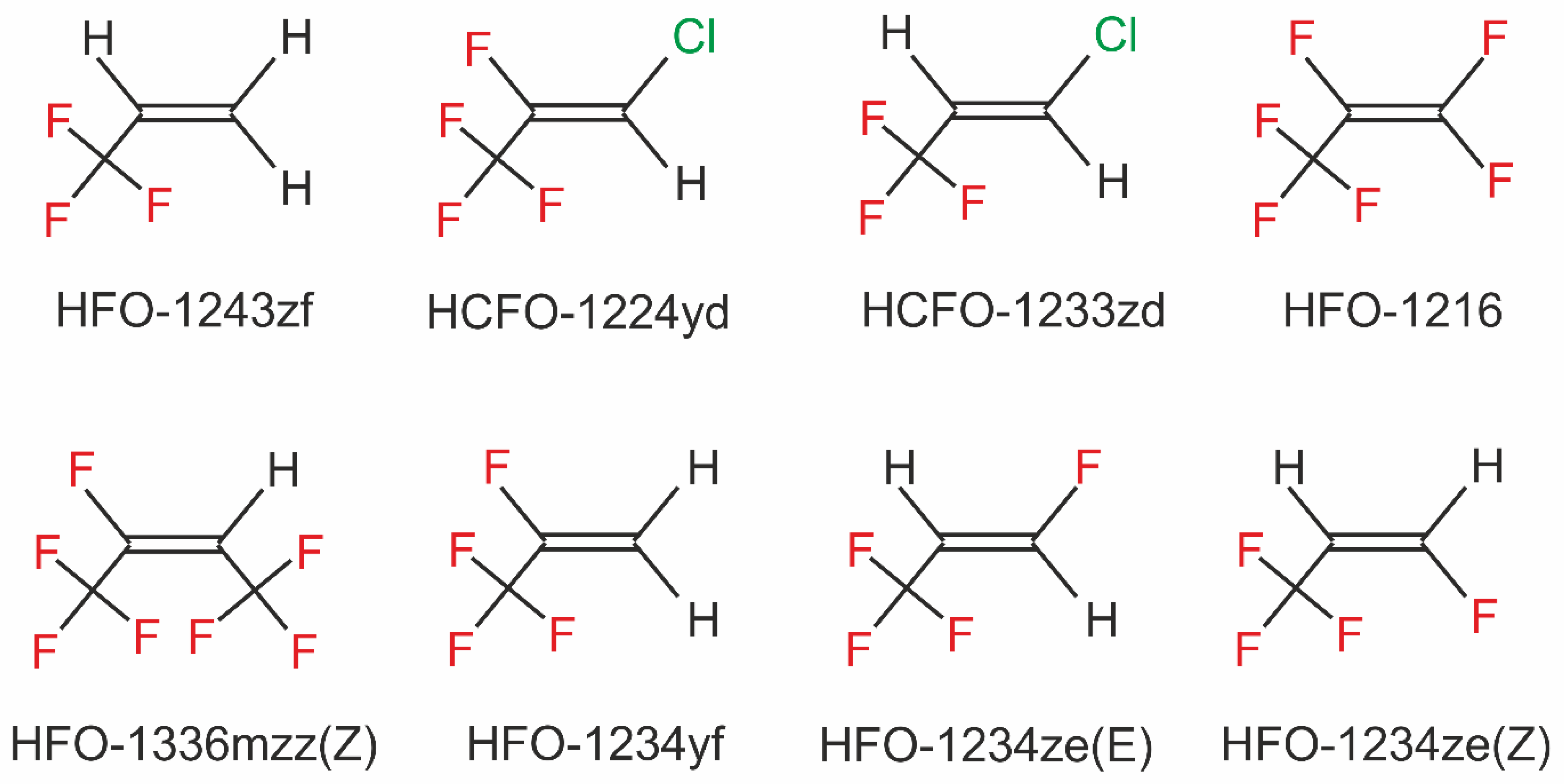
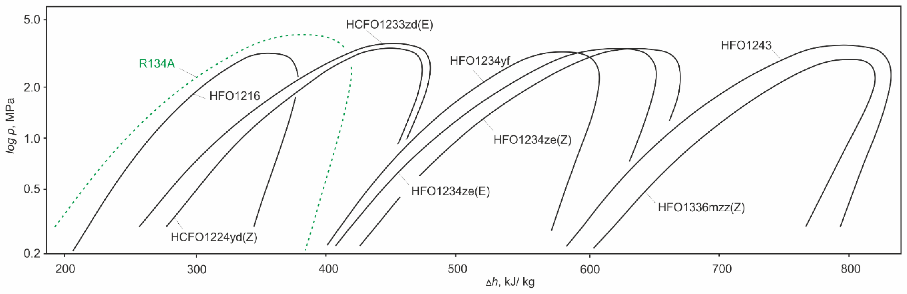
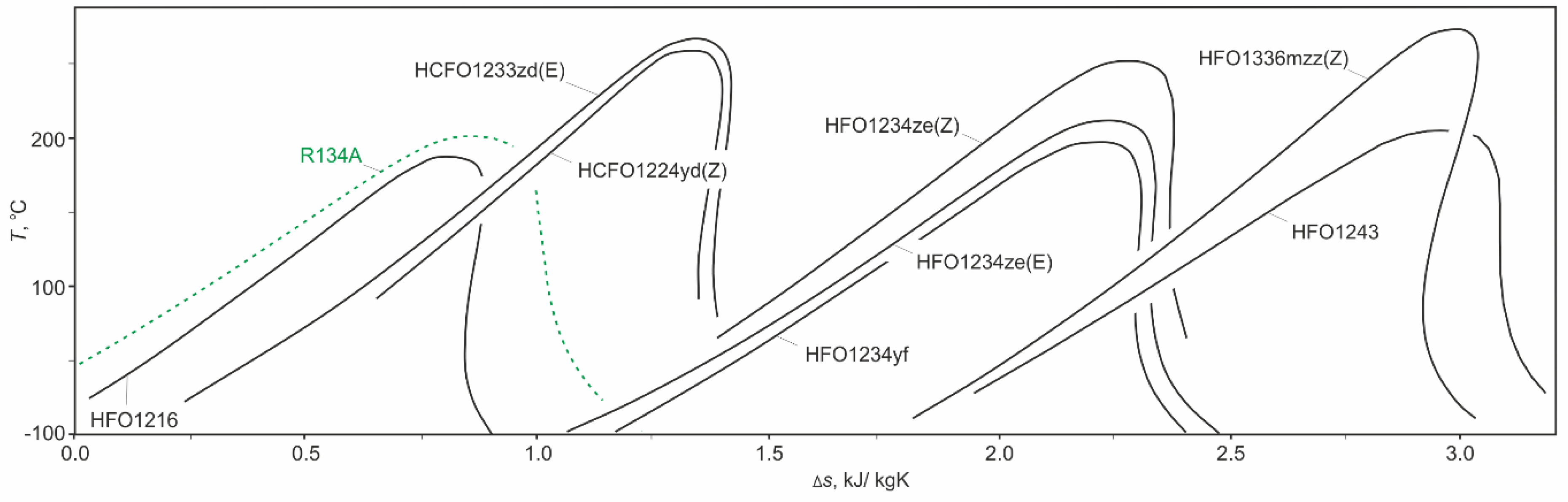
2. General Description of Hydrofluoroolefins

HFO-1234yf is the most widely used HFO refrigerant and is commonly used as a replacement for R134a in MAC systems. HFO-1234yf is a propene molecule that is halogenated by replacing four atoms of hydrogen with fluorine (see Figure 1). This refrigerant has parameters similar to R134a, and its normal boiling point and critical temperature are −29.48 °C and 94.70 °C, respectively. However, it is characterized by a lower latent heat of evaporation, which translates into a higher mass flow rate in the system. HFO-1234yf is characterized by moderate flammability (according to ASTM 681), and the required ignition energy is much higher than for flammable HFC refrigerants, like R152a or R32. Due to the low flame propagation speed and the high level of flame ignition energy, this substance was assigned to the A2L safety group according to ISO 817. Nevertheless, research is still being carried out to improve the safety of use of HFO-1234yf [26].
Another fluid that could potentially substitute R134a is 3,3,3-trifluoropropene, also known as HFO-1243zf. Among the refrigerants described in this article, the thermodynamic properties of this fluid are the most similar to R134a (see Table 1).
HFO-1234ze(E) and HFO-1234ze(Z) are also a propane molecule halogenated with four fluorines. However, the properties of these isomers differ from each other, hence their use is different. HFO-1234ze(E) is a medium pressure refrigerant. Its normal boiling point and critical temperature are −18.97 °C and 109.36 °C, respectively, which enables it to replace R134a in medium-temperature refrigeration systems. Moreover, its evaporation heat is about 20% higher than that of R134a. HFO-1234ze(Z) is characterized by a high normal boiling temperature (9.73 °C) and a high critical temperature of 150.12 °C. Thus, it is suitable for high-temperature heat pumps [31,32,33]. However, the use in refrigeration cannot only be limited to favorable condensing conditions, therefore, HFO-1234ze(Z) is used to create new refrigerant blends with a wider range of applications.
Another refrigerant that can potentially find an application in high-temperature units is HCFO-1233zd(E). This working fluid is classified in the A1 (non-flammable) class according to the ASHRAE standard 34 safety group classification. Its GWP is under 7 and its ozone depletion potential (ODP) is near 0 (0.00034). Although this working fluid is not fully safe for stratospheric ozone, its destructive influence is negligible when compared with the refrigerants of previous generations. Due to its high boiling temperature (18.26 °C), critical temperature (166.45 °C) and latent heat (196.27 kJ/kg), it is considered as a replacement for R245fa in the Organic Rankine Cycle (ORC) [34,35,36,37,38]. Apart from the study in the ORC, the performance of the centrifugal chiller [39] and solar assisted heat pump [40] using HCFO-1233zd(E) have also been investigated.
HFO-1336mzz(Z) is an olefin of butane. The GWP value for this substance is 2, and its boiling point and critical temperature are 33.45 °C and 171.35 °C, respectively. Like the previously described olefins, due to its high boiling and critical point, it can be used in the ORC [34,41] and high-temperature heat pumps. HFO-1336mzz(Z), due to its low value of GWP, has been used in refrigeration as a component of mixture R514A—the refrigerant that is used as a replacement for R123 in low pressure centrifugal chillers.
Analyses presented in the following sections of this work were carried out for nine refrigerants. In addition to the six HFO/HCFO fluids described in detail above, simulations using HFO-1216 and HCFO-1224yd(Z) were also performed. The ninth simulation was made for R134a, which was treated as the reference refrigerant.
Figure 2 shows the vapor and liquid saturation curves for the HFO/HCFO refrigerants considered in this paper. The relative enthalpy was used to describe the x-axis, because it improves the readability of the graph—the saturation lines for individual working fluids do not overlap and cross. It is clearly visible that all the substances have more or less the same critical pressure. R134a has the highest pressure (4059.3 kPa), and from HFO/HCFO fluids, the highest pressure is for HFO-1234ze(E) (3634.9 kPa). The lowest pressure is for R1336mzz (Z) (2903 kPa). Moreover, liquid saturation lines are similar for all working fluids except HFO-1216, for which the slope is steeper. Similarly, the steam saturation lines have the same slope, except for HFO-1336mzz(Z), for which the entire line tilts to the right. The heat of evaporation of the HFO/HCFO refrigerants is close to that of R134a, and differences are around ±12% when the evaporation temperature is set to 0 °C. The only exception is HFO-1216, whose evaporation heat is definitely lower. Differences in relation to R134a are close to 40%.

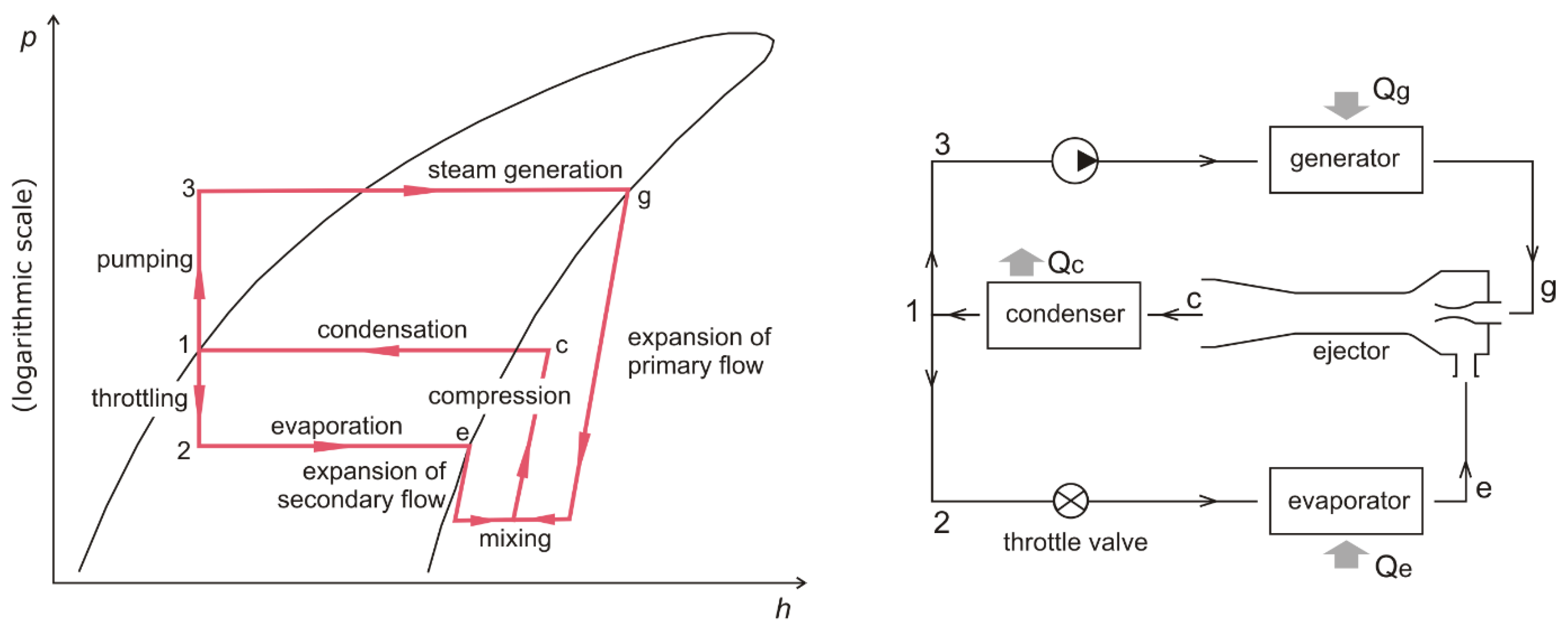
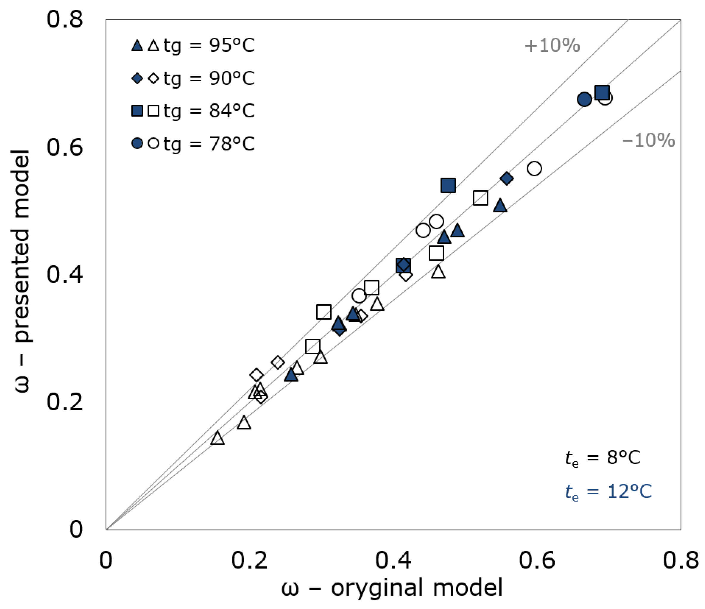
3. The Ejector Model and Its Properties

Based on the presented analytical model, computer software that allows analysis of the performance of the ejector refrigeration cycle for over 50 substances was created by the authors. A schematic diagram of the ejector cooling cycle and its p-h diagram is shown in Figure 3.
A comparative study of ejector performance using HFO and HCFO as working fluids was made on the basis of a one-dimensional model presented by Huang et al. [42]. The mathematical model applied is based on equations derived from the principles of conservation of mass (1), momentum (2), and energy (3):
ρ i n u i n A i n = ρ o u t u o u t A o u t  
P i n A i n + m i n u i n = P o u t A o u t + m o u t u o u t  
m i n ( h i n + u i n 2 2 ) = m o u t ( h o u t + u o u t 2 2 )  
Based on the assumption of the isentropic flow inside the ejector, the model meets the following gas dynamics equations:
m A i = P t o γ i R g T t o M a i ( 1 1 + γ i 1 2 M a i 2 ) ( γ i + 1 ) / ( γ i 1 )  
A i + 1 A i = M a i M a i + 1 [ 1 + γ 1 2 M a i + 1 2 1 + γ 1 2 M a i 2 ] γ + 1 2 ( γ 1 )  
P i P i + 1 = ( 1 + γ 1 2 M a i + 1 2 1 + γ 1 2 M a i 2 ) γ γ 1  
T t o T t = 1 + γ 1 2 M a t 2
Detailed information about the model and its equations can be found in [42]. Based on the presented analytical model, computer software that allows analysis of the performance of the ejector refrigeration cycle for over 50 substances was created by the authors. The efficiency of the ejector cooling system was defined by two parameters: the entrainment ratio of the ejector ω, defined as the quotient of the mass flow of the secondary vapor sucked in from the evaporator and the primary, motive vapor from the generator (8), and COP of the cycle, defined as the ratio of cooling power obtained in the evaporator to the heat consumed in the vapor generator (9):
ω = m s ˙ m p ˙
C O P t h = Q e Q g = m s ˙ · q e m p ˙ · q g
The main assumptions of the used model are as follows:
  • the refrigerant is treated as a semi-ideal gas—Cp and γ values vary with the fluid temperature;
  • the flow inside the ejector is steady and one-dimensional;
  • the kinetic energies at the secondary inlet and outlet of the ejector are negligible;
  • the ejector's inner walls are adiabatic.
It is obvious that the values obtained by the model strongly depend on the losses during the streams flow inside the components of the ejector. To simplify the model, it was assumed that relations are isentropic, but efficiency coefficients are accounted for to specify their non-ideality. In the previous work of the authors [29], the range of values of coefficients used in various research was presented. On the basis of that comparison, the values quoted in the original model, and with the aim of maintaining uniformity in relation to the previously analyzed groups of substances, the following coefficients were adopted:
  • the isentropic efficiency of the compressible flow in the primary nozzle ηp = 0.95;
  • the isentropic efficiency of the entrained flow ηs = 0.85;
  • the loss coefficient of the primary flow inside the suction chamber ϕp = 0.88;
  • the frictional loss coefficient of the mixed flow ϕm.
The frictional loss coefficient has the greatest impact on the model, and has therefore not been determined as a constant value, but is calculated as a relation of the cross-sectional area at the outlet of the mixing chamber and the cross-sectional area of the nozzle throat (Am/At) according to the proposition described in the original paper. The results obtained using the presented model were compared with both experimental data and model data for refrigerant R141b and are presented in [42]. Validation was carried out for two different evaporation temperatures (8 °C and 12 °C) and for four steam generator temperatures (78 °C, 84 °C, 90 °C, and 95 °C, respectively). Despite the changes made to the model, the results obtained are almost identical to those presented in the original work (Figure 4 and Figure 5), and only a few points showed dispersion greater than ±10%. The average errors of the model used in this study, presented in relation to the experimental values and the original model, were 8.8% and 4.7%, respectively. The obtained error values indicate the correctness of the calculation model.
The REFPROP v 9.4 database [27] was used to obtain the thermodynamic and thermophysical properties for the tested substances. The current paper is the fourth publication concerning the use of various groups of refrigerants in ejector cooling cycles. Previous work concerned the use of heavier hydrocarbons [29], organic solvents, and non-flammable synthetic fluids [43] and ethers [44] as refrigerants, and showed that the model used allows for the analysis of many working fluids and for a wide range of variables to be simplified, while at the same time maintaining reliable results.
One of the main assumptions of the model is that no phase change occurs during both the expansion process of the primary flow along the primary nozzle and the expansion process inside the suction chamber. Therefore, it is important that the analyzed fluids belong to the group of ‘dry’ refrigerants, for which the process of vapor expansion in the primary nozzle of the ejector extends only in a superheated vapor region. Figure 6 shows the saturation curves of the HFO and HCFO refrigerants considered in this study. It can be seen that for most fluids, the vapor saturation curves bend to the right, and thus these fluids can be classified as ‘dry’. On the other hand, for the HFO-1243zf and HFO-1234ze(E)/(Z) refrigerants, the vapor saturation line runs along the constant entropy line, which is why these fluids are called ‘isentropic’. In their case, there may be a need for a small superheated primary vapor to avoid the transition to a two-phase region during the expansion process.
As in our previous analyses on other groups of refrigerants, this study assumes that processes occurring in an evaporator and in a condenser are completed without vapor superheating and liquid sub-cooling. To facilitate and extend the possibility of comparing our results, three different levels of evaporation and condensation temperatures were adopted. The generator temperature for each refrigerant was changed in the range from 60 °C to the critical temperature for a given substance. Hence, the analysis was limited to the subcritical refrigeration cycle.

4. Results and Discussion

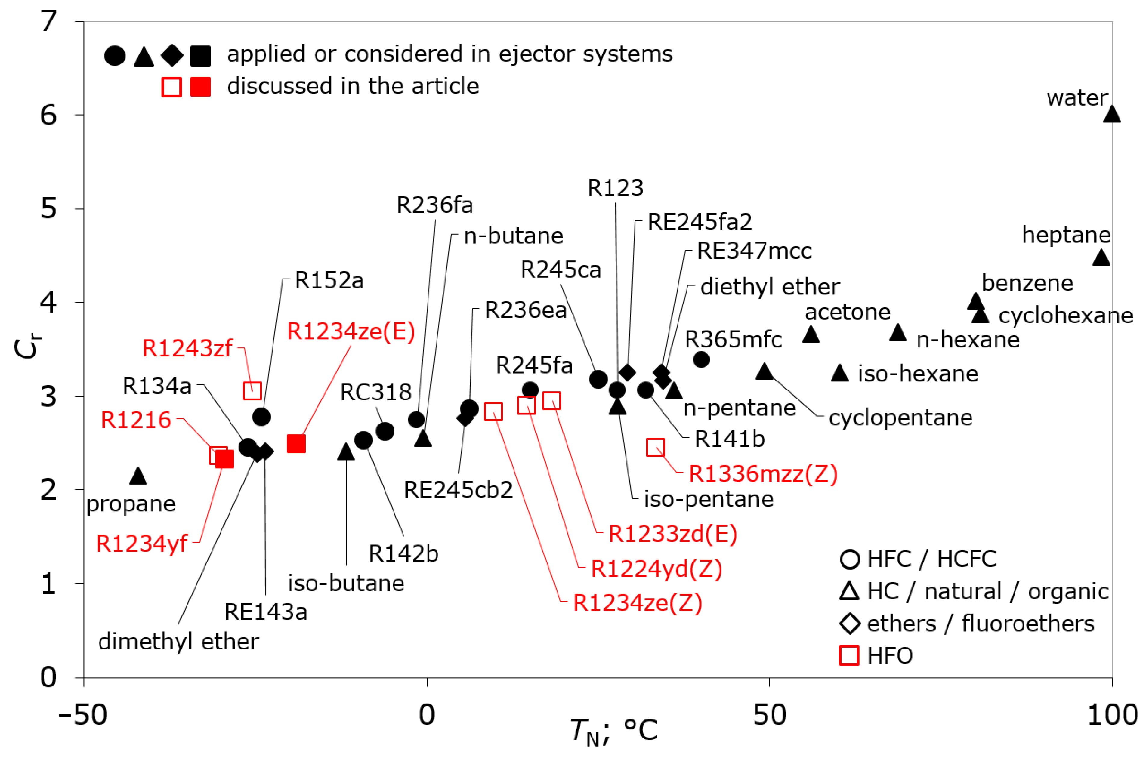
4.1. Compression Ratio

The values of compression ratio Cr for the tested hydrofluoroolefins are shown in Figure 7. Refrigerants previously used or considered in the ejector cycles were marked with a filled contour, while new fluids included in this study were marked with an unfilled contour. Cr values close to R134a were obtained by HFO-1216, HFO-1234yf, and HFO-1234ze(E). The first two have a normal boiling point a bit lower than R134a, and can thus replace this f-gas in the full temperature range. The boiling point for HFO-1234ze(E) is about 7 K higher than that for R134a, and, therefore, its use in systems with a lower evaporation temperature is limited. Refrigerant HFO-1243zf almost has the same boiling point as R134a. Unfortunately, among the analyzed olefins, it has the highest compression ratio of 3.05. In the middle part of the chart, three more olefins are located – HFO-1234ze(Z), HCFO-1224yd(Z), and HCFO-1233zd(E). The value of the compression ratio for these working fluids ranges from 2.83 to 2.95. The refrigerant HFO-1336mzz(Z) is located furthest to the right and its Cr is identical to that of R134a (2.45). The advantage of these working fluids, however, is their highly-located critical point, which makes it possible to obtain a higher temperature of primary vapor while maintaining operation in the subcritical cycle. This in turn translates into a higher efficiency of the ejector.
A potential problem created by refrigerants with a high normal boiling point is their work under pressure. In the case of the discussed fluids, and in order to obtain an evaporation temperature of 0 °C, these refrigerants would operate at a pressure of 68.28 kPa, 55.78 kPa, 48.11 kPa, and 24.75 kPa for HFO-1234ze(Z), HCFO-1224yd(Z), HCFO-1233zd(E), and HFO-1336mzz(Z), respectively. The presented values show that the percentage of vacuum in the device would be significant, which increases the risk of flammability and explosiveness in the case of the system leaking. While HCFO-1224yd(Z), HCFO-1233zd(E), and HFO-1336mzz(Z) belong to the A1 group, which means these are non-flammable refrigerants, in the case of HFO-1234ze(Z) fluid, which is not in the A1 group, explosion is a real risk.

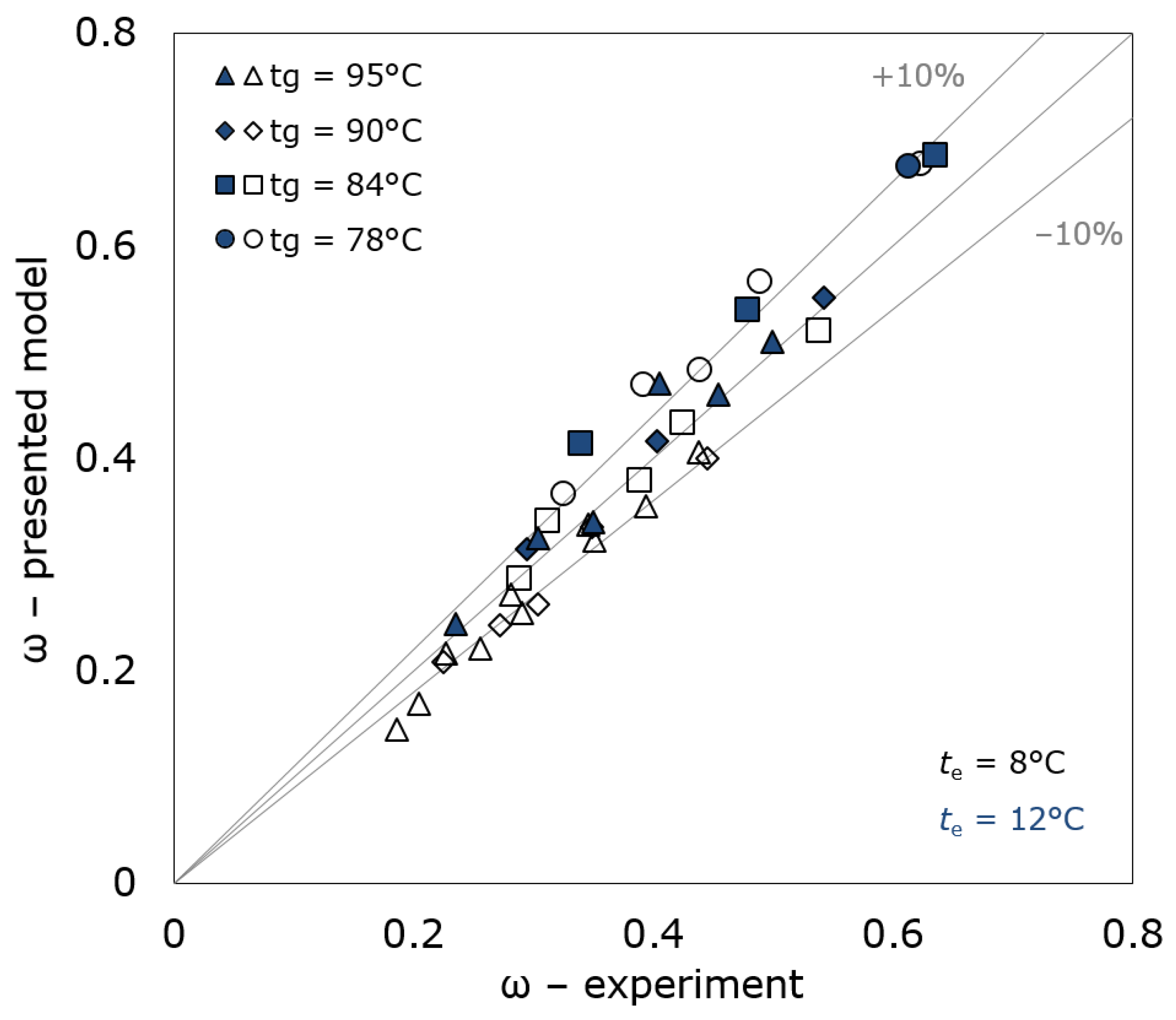
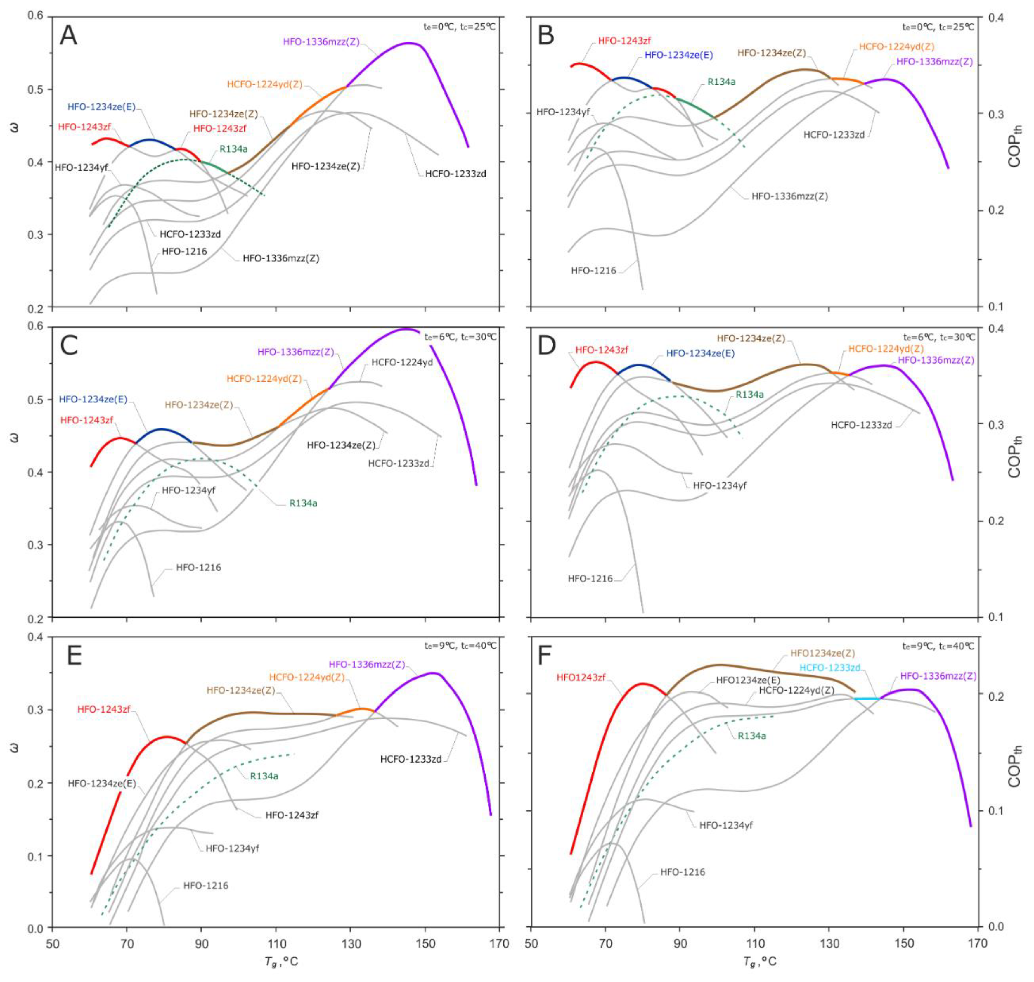
4.2. Entrainment Ratio (ω) and Coefficient of Performance (COP)

Before discussing the obtained results, it is worth noting that the simulation program calculates the optimal geometry of the ejector for each individual case (for boundary conditions and input data) in order to achieve the maximum entrainment ratio and coefficient of performance. This means that the operating point is always in the critical pressure of the condenser for the generator and evaporator temperature set during the simulation. The diameter of the primary nozzle for all simulations was established to be equal to 1 mm. The rest of the ejector geometry was calculated according to the demands of the model.
The calculated values of the entrainment ratio of the ejector and the COP of the ejector cycle operating with working fluids from the hydrofluoroolefin group for various generator temperatures are presented in Figure 8A–F. As a comparison, R134a was added to the graphs, as it is one of the most popular synthetic refrigerants used or considered for use in refrigeration ejector cycles. It is also a refrigerant that is replaced by HFOs. The chart consists of six fields. The left column shows the obtained ω values, while the right column shows the efficiency of the system described by the COP parameter. The three rows of the graph refer to different assumed evaporation and condensation temperatures. The top row (Figure 8A–B) corresponds to an evaporation temperature of 0 °C and a condensing temperature of 25 °C, the middle row (Figure 8C–D) show 6 °C and 30 °C, respectively, while the bottom row (Figure 8E–F) shows 9 °C and 40 °C, respectively. The selection of different temperatures and their listing on one graph was done to more broadly compare the results with other research. In addition, for the purpose of easier identification, individual refrigerants were assigned with unique colors.
Analysis of the obtained results was carried out for individual sets of evaporation and condensation temperatures. Starting from the set te = 0 °C and tc = 25 °C (Figure 8A), the ω optimum value is obtained for six working fluids as the temperature of the primary vapor increases. It is clearly visible that there is no single refrigerant that was able to cover the work of the ejector in a wide range of tg temperatures. The first conclusion that arises is the fact that the ejector cycle requires an individual selection of refrigerant for the assumed working conditions. At the same time, divergence from the agreed operating conditions can significantly change the efficiency of the ejector. In this context, studies that show the cross-sectional utilization of many fluids under the same operating conditions of the system are extremely important. For low generator temperatures (up to 70 °C), the most favorable ejector working conditions are obtained for HFO-1243zf (red line). This fluid achieves a maximum entrainment ratio of 0.432 (tg = 65°C). In the generator temperature range from 70 °C to 83 °C, the most effective operation of the ejector was recorded for HFO-1234ze(E) (marked as a blue line), reaching nearly the same ωmax as HFO-1243zf (ω = 0.431, tg = 76 °C). The conclusion that can be made here is that it is possible to operate the ejector with a high efficiency (above 0.4) for low temperatures of the primary vapor supplying the ejector by using HFO refrigerants. At the same time, the observations of other researchers [45], who analyzed the work of the ejector refrigeration system with HFO-1234ze(E) as refrigerants, were confirmed.
Between 83 °C and 90 °C of tg, the highest ejector efficiency is again obtained by HFO-1243zf. It is also the only refrigerant among the considered fluids for which two ranges with the highest optimal entrainment ratio were observed. Above 90 °C, the best performance (ω = 0.4) was obtained by R134a, which is included in the graph as a comparative fluid. The minimal value of ω equal to 0.385 is observed at the intersection of R134a (green line) and HFO-1234ze(Z) (brown line), at tg = 97 °C. For a higher generator temperature of up to 147 °C, a continuous increase in the ω value was observed, successively falling on substances HFO-1234ze(Z), HCFO-1224yd, and HFO-1336mzz(Z). HFO-1336mzz(Z) obtained the maximum efficiency for the assumed evaporation and condensation temperatures and amounted to 0.85. Above tg = 147 °C, the entrainment ratio drops sharply. The phenomenon of the falling of the ω curve for a given refrigerant as it approaches its critical point is identified with a step change in the specific heat for constant pressure Cp and the ratio of specific heats γ, which are both rapidly increasing. Hence, the mass flow of the primary vapor that supplies the ejector increases, which results in a decrease in its efficiency.
Looking at the COP diagram (Figure 8B) for the evaporating and condensing temperatures of 0 °C and 25 °C, it can be noted that the higher ω does not necessarily translate into an increase in the efficiency of the entire ejector cycle. The maximum COP value of 0.35 was obtained by HFO-1243zf for the temperature tg equal to 64 °C. Moreover, at up to 97 °C, there is almost a linear decrease in the value of the COP parameter. The minimum of the COP peak values was 0.29. It is true that a system is able to get values close to the maximum COP (HFO-1234ze(Z), tg = 124 °C, COP = 0.345) for higher generator temperatures, however, it should be noted that it makes no sense to feed the ejector with vapor at a higher temperature if the same cycle efficiency can be obtained by lowering this temperature by as much as 60 K. Thus, the next conclusion is that the increase in tg temperature results in an increase in the entrainment ratio (ω), but does not significantly affect the efficiency of the entire ejector cycle (COP) operating with HFO fluids.
By increasing the evaporating and condensing temperature to 6 °C and 30 °C, it was noted that the obtained ω values increased slightly (Figure 8C). The maximum for the low temperatures of the vapor generator was obtained for HFO-1234ze(Z) (ω = 0.46 for tg = 80 °C). When compared with the previous pair of evaporating and condensing temperatures, there is no significant decrease in the optimal ω in the central part of the graph. Values of about 0.45 are obtained successively by HFO-1243zf, HFO-1234ze(E), and HFO-1234ze(Z) with the increase of the primary vapor temperature to 105 °C. A further increase in tg causes, as in the upper graph, the successive increase of the entrainment ratio (maximum equal to 0.595, tg = 147 °C, HFO-1336mzz(Z)) and the collapse of the sharp curve in the final range. The main observation is that R134a no longer achieves an optimum value of ω; its replacement for the assumed temperature levels by the refrigerants from the HFO group allows for an increase of the efficiency of ejector performance.
When analyzing the COP curves obtained for te = 6 °C and tc = 30 °C (Figure 8D), it can be noticed that there are four peaks on the optimal value line. Their values are almost the same and range from 0.36 to 0.365 for generator temperatures of 67 °C, 80 °C, 125 °C, and 144 °C. It can again be seen that the entrainment ratio increase does not translate into an increase of COP, and, therefore, raising the temperature of the primary vapor is not justified from the point of view of the efficiency of the ejector refrigeration system.
The last analyzed set of evaporation and condensation temperatures were 9 °C and 40 °C (Figure 8E–F). The behavior of HFO fluids in this case is quite different. The maximum cycle efficiency COP is not obtained at low temperatures of the vapor generator, but is obtained for average values (in the range 95 °C–110 °C) and is equal to 0.22. A slightly lower value was obtained by HFO-1243zf (COP = 0.209, tg = 80 °C).
In all the carried out simulations, HFO-1234yf and HFO-1216 proved to be unattractive for ejector refrigeration systems. A particular surprise is the lack of attractiveness of HFO-1234yf, which is widely used in compressor systems. Although its application is possible, the obtained efficiency of both the ejector and the entire cycle is lower than for the other HFO fluids within the range of temperatures considered. HCFO-1233zd appears in the charts for te = 9 °C and tc = 40 °C (Figure 8F), but in a very narrow area of the generator's temperature (137 °C–142 °C), which also disqualifies it as a good working fluid in the refrigeration cycle. It is worth noting that with the increase in system operating temperatures, the number of refrigerants occurring on the optimal ω and COP lines is narrowed. This shows that not all of the fluids considered in this paper allow the ejector refrigeration system to be operated in a wide range of te, tc, and tg temperatures while maintaining satisfactory efficiency of the device. In this respect, HFO-1243zf, HFO-1234ze(E), and HFO-1234ze(Z) proved to be the best HFO substances for the ejector cycles.

4.3. Cooling Capacity

It seems interesting to compare the cooling capacity that is achievable for hydrofluoroolefins compared to the conventional refrigerant R134a. As shown in Figure 8B, D, and F, three sets of te and tc temperatures were analyzed:
  • For the first set (te = 0 °C, tc = 25 °C, Figure 8B) in the temperature range of the primary vapor from 60 °C to 80 °C, the use of HFO-1243zf instead of R134a would give about 32% more cooling capacity;
  • For the second set (te = 6 °C, tc = 30 °C, Figure 8D) in the temperature range of the primary vapor from 60 °C to 80 °C, the use of HFO-1243zf instead of R134a would give about 41% more cooling capacity;
  • For the third set (te = 9 °C, tc = 40 °C, Figure 8F) in the temperature range of the primary vapor from 60 °C to 80 °C, the use of HFO-1243zf instead of R134a would give about 140% more cooling capacity.
Thus, it can be seen that the simultaneous increase in the evaporation and condensing temperature in the ejector cycle (which may take place in the case of a hot climate) increases the benefit from the use of HFOs. In general, the use of HFO-1243zf would improve the cooling capacity for low driving vapor temperatures (from about 60 °C to 88 °C). However, it can also be seen in Figure 8B that currently there is no alternative refrigerant from the HFO group that would give higher cooling capacity than R134a in the temperature range tg = 90–97 °C.

5. Conclusions

In this paper, a theoretical simulation of ejector performance with hydrofluoroolefins as refrigerants was presented. The results achieved in the application of the one-dimensional (1-D) computational model were discussed. On the basis of the obtained results, the following conclusions were formulated:
  • A favorable feature of hydrofluoroolefin is that they obtain a high efficiency of the ejector system performance at low primary vapor temperatures. For the three analyzed variants of evaporation and condensation temperatures, the maximum COPs were 0.35, 0.365, and 0.22, respectively.
  • The most benefit comes from the use of HFO-1243zf and HFO-1234ze(E). However, they do not allow operation in a wide range of generator temperatures, and it is therefore necessary to correctly select and control the operating parameters of the ejector.
  • There was no single refrigerant that ensures efficient operation of the system in the examined range of te, tc, and tg temperatures.
  • The HFO-1233zd(E) and HFO-1224yd(Z) working fluids allow the optimal COP of the ejector refrigeration system for high temperatures of the motive vapor (above 130 °C) to be obtained. Unfortunately, these fluids have chlorine in their molecule, and despite their short atmospheric lifetime and almost zero ODP, their use is controversial in the light of EU Regulation 1005/2009 [46].
  • It was found that HFO-1216 and HFO-1234yf are not attractive for ejector refrigeration units in the tested range of evaporation and condensation temperatures.
  • The use of HFO-1243zf would improve the cooling capacity for low driving vapor temperatures (from about 60 °C to 88 °C).
When comparing HFO/HCFO fluids with previously analyzed groups of refrigerants, it can be seen that the obtained entrainment ratio and COP values are similar to those for Dimethyl ether (DME) or isobutene. However, these values are obtained at lower tg temperatures, which allow operating costs to be reduced. The disadvantage of these factors is, however, that in contrast to hydrocarbons, they do not show an increase in the efficiency of performance of both the ejector and the entire cycle while increasing the temperature of the primary vapor.

Author Contributions

J.K. contributed to software preparation and a graphical presentation of the results. B.G. drafted the work and contributed to model validation, data collection, and analysis.

Funding

This research was funded by Wrocław University of Science and Technology, grant number [401/180/17].

Conflicts of Interest

The authors declare no conflicts of interest.

Nomenclature

NomenclatureDefinition
Aarea (m2)
Cpspecific heat at constant pressure (kJ·kg−1·K−1)
Crcompression ratio (dimensionless)
hspecific enthalpy (kJ·kg−1)
mmass (kg)
m ˙ mass flow (kg·s−1)
p, Ppressure (kPa)
qenthalpy of vaporization (kJ·kg−1)
Qheat (W)
Rindividual gas constant (J·kg−1·K−1)
sspecific entropy (kJ·kg−1·K−1)
t, Ttemperature (°C or K)
uvelocity (m·s−1)
Greek symbolsDefinition
γratio of specific heats (dimensionless)
ηisentropic efficiency (dimensionless)
ϕloss coefficient (dimensionless)
ρdensity (kg·m−3)
ωentrainment ratio (dimensionless)
SubscriptsDefinition
ccondensing
eevaporation
ggenerating or gas
ininlet
mmixing
Nnormal boiling point
outoutlet
pprimary flow
ssecondary flow (entrained)
tthroat
tototal
AbbreviationsDefinition
ATELAcute Toxicity Exposure Limit
COPCoefficient of Performance
DMEDimethyl ether
GWPGlobal Warming Potential
HCFOHydrochlorofluoroolefin
HFCHydrofluorocarbon
HFOHydrofluoroolefin
LFLLower Flammable Limit
MACMobile Air-conditioning
ODPOzone Depletion Potential
ORCOrganic Rankine Cycle

References

  1. European Environment Agency. Directive 2006/40/EC of the European Parliament and of the Council of 17 May 2006 Relating to Emissions from Air-Conditioning Systems in Motor Vehicles and Amending Council Direactive 70/156/EEC. Available online: https://www.eea.europa.eu/policy-documents/directive-2006-40-ec#tab-related-indicators (accessed on 9 June 2018).
  2. European Environment Agency. Regulation (EU) No 517/2014 of the European Parliament and of the Council of 16 April 2014 on Fluorinated Greenhouse Gases and Repealing Regulation (EC) No 842/2006. Available online: https://www.eea.europa.eu/policy-documents/regulation-eu-no-517-2014 (accessed on 9 June 2018).
  3. Mota-Babiloni, A.; Belman-Flores, J.M.; Makhnatch, P.; Navarro-Esbrí, J.; Barroso-Maldonado, J.M. Experimental exergy analysis of R513A to replace R134a in a small capacity refrigeration system. Energy 2018, 162, 99–110. [Google Scholar] [CrossRef]
  4. Llopis, R.; Sánchez, D.; Cabello, R.; Catalán-Gil, J.; Nebot-Andrés, L. Experimental analysis of R-450A and R-513A as replacements of R-134a and R-507A in a medium temperature commercial refrigeration system. Int. J. Refrig. 2017, 84, 52–66. [Google Scholar] [CrossRef] [Green Version]
  5. Belman-Flores, J.M.; Rangel-Hernandez, V.H.; Uson, S.; Rubio-Maya, C. Energy and exergy analysis of R1234yf as drop-in replacement for R134a in a domestic refrigeration system. Energy 2017, 132, 116–125. [Google Scholar] [CrossRef]
  6. Aprea, C.; Greco, A.; Maiorino, A. Comparative performance analysis of HFO1234ze/HFC134a binary mixtures working as a drop-in of HFC134a in a domestic refrigerator. Int. J. Refrig. 2017, 82, 71–82. [Google Scholar] [CrossRef]
  7. Aprea, C.; Greco, A.; Maiorino, A.; Masselli, C. The drop-in of HFC134a with HFO1234ze in a household refrigerator. Int. J. Therm. Sci. 2018, 127, 117–125. [Google Scholar] [CrossRef]
  8. Invernizzi, C.M.; Iora, P.; Preißinger, M.; Manzolini, G. HFOs as Substitute for R-134a as Working Fluids in ORC Power Plants: A Thermodynamic Assessment and Thermal Stability Analysis 2016. Available online: https://www.infona.pl/resource/bwmeta1.element.elsevier-0dafa870-0cc8-35e8-8500-fc456eab5fd3 (accessed on 9 June 2018).
  9. Yang, C.-Y.; Nalbandian, H.; Lin, F.-C. Flow boiling heat transfer and pressure drop of refrigerants HFO-1234yf and HFC-134a in small circular tube. Int. J. Heat Mass Transf. 2018, 121, 726–735. [Google Scholar] [CrossRef]
  10. Diani, A.; Mancin, S.; Rossetto, L. Flow boiling heat transfer of R1234yf inside a 3.4 mm ID microfin tube. Exp. Therm. Fluid Sci. 2015, 66, 127–136. [Google Scholar] [CrossRef]
  11. Pérez-García, V.; Belman-Flores, J.; Rodríguez-Muñoz, J.; Rangel-Hernández, V.; Gallegos-Muñoz, A. Second Law Analysis of a Mobile Air Conditioning System with Internal Heat Exchanger Using Low GWP Refrigerants. Entropy 2017, 19, 175. [Google Scholar] [CrossRef]
  12. Daviran, S.; Kasaeian, A.; Golzari, S.; Mahian, O.; Nasirivatan, S.; Wongwises, S. A comparative study on the performance of HFO-1234yf and HFC-134a as an alternative in automotive air conditioning systems. Appl. Therm. Eng. 2017, 110, 1091–1100. [Google Scholar] [CrossRef]
  13. Lai, N.A. Thermodynamic properties of HFO-1243zf and their application in study on a refrigeration cycle. Appl. Therm. Eng. 2014, 70, 1–6. [Google Scholar] [CrossRef]
  14. Śmierciew, K.; Gagan, J.; Butrymowicz, D.; Łukaszuk, M.; Kubiczek, H. Experimental investigation of the first prototype ejector refrigeration system with HFO-1234ze(E). Appl. Therm. Eng. 2017, 110, 115–125. [Google Scholar] [CrossRef]
  15. Fang, Y.; Croquer, S.; Poncet, S.; Aidoun, Z.; Bartosiewicz, Y. Drop-in replacement in a R134 ejector refrigeration cycle by HFO refrigerants. Int. J. Refrig. 2017, 77, 87–98. [Google Scholar] [CrossRef]
  16. Milazzo, A.; Rocchetti, A. Modelling of ejector chillers with steam and other working fluids. Int. J. Refrig. 2015, 57, 277–287. [Google Scholar] [CrossRef]
  17. Thongtip, T.; Aphornratana, S. An experimental analysis of the impact of primary nozzle geometries on the ejector performance used in R141b ejector refrigerator. Appl. Therm. Eng. 2017, 110, 89–101. [Google Scholar] [CrossRef]
  18. Khennich, M.; Galanis, N.; Sorin, M. Effects of design conditions and irreversibilities on the dimensions of ejectors in refrigeration systems. Appl. Energy 2016, 179, 1020–1031. [Google Scholar] [CrossRef]
  19. Li, F.; Chang, Z.; Tian, Q.; Wu, C.; Wang, X. Performance Predictions of Dry and Wet Vapors Ejectors Over Entire Operational Range. Energies 2017, 10, 1012. [Google Scholar] [CrossRef]
  20. Ameur, K.; Aidoun, Z.; Ouzzane, M. Experimental performances of a two-phase R134a ejector. Exp. Therm. Fluid Sci. 2018, 97, 12–20. [Google Scholar] [CrossRef]
  21. Li, F.; Li, R.; Li, X.; Tian, Q. Experimental investigation on a R134a ejector refrigeration system under overall modes. Appl. Therm. Eng. 2018, 137, 784–791. [Google Scholar] [CrossRef]
  22. Bellos, E.; Tzivanidis, C. Optimum design of a solar ejector refrigeration system for various operating scenarios. Energy Convers. Manag. 2017, 154, 11–24. [Google Scholar] [CrossRef]
  23. Yan, J.; Chen, G.; Liu, C.; Tang, L.; Chen, Q. Experimental investigations on a R134a ejector applied in a refrigeration system. Appl. Therm. Eng. 2017, 110, 1061–1065. [Google Scholar] [CrossRef]
  24. Wang, L.; Liu, J.; Zou, T.; Du, J.; Jia, F. Auto-tuning ejector for refrigeration system. Energy 2018, 161, 536–543. [Google Scholar] [CrossRef]
  25. Liu, Y.; Fu, H.; Yu, J. Performance study of an enhanced ejector refrigeration cycle with flash tank economizer for low-grade heat utilization. Appl. Therm. Eng. 2018, 140, 43–50. [Google Scholar] [CrossRef]
  26. Feng, B.; Yang, Z.; Zhai, R. Experimental study on the influence of the flame retardants on the flammability of R1234yf. Energy 2018, 143, 212–218. [Google Scholar] [CrossRef]
  27. Lemmon, E.W.; Bell, I.H.; Huber, M.L.; McLinden, M.O. NIST Standard Reference Database: REFPROP Reference Fluid Thermodynamic and Transport Properties, version 9.4.4.44 2018. Available online: https://www.nist.gov/srd/refprop (accessed on 6 June 2018).
  28. EN 378-1:2016 Refrigerating Systems and Heat Pumps-Safety and Environmental Requirements-Part 1: Basic Requirements, Definitions, Classification and Selection Criteria. Annex E Safety Classification and Information about Refrigerants. Available online: https://infostore.saiglobal.com/en-au/standards/en-378-1-2016-1892971/ (accessed on 9 June 2018).
  29. Kasperski, J.; Gil, B. Performance estimation of ejector cycles using heavier hydrocarbon refrigerants. Appl. Therm. Eng. 2014, 71, 197–203. [Google Scholar] [CrossRef]
  30. AGC Chamicals. Amolea 1224yd Product Summary 2016. Available online: https://www.agc-chemicals.com/jp/en/products/detail/index.html?pCode=JP-EN-G016 (accessed on 28 April 2018).
  31. Fukuda, S.; Kondou, C.; Takata, N.; Koyama, S. Low GWP refrigerants R1234ze(E) and R1234ze(Z) for high temperature heat pumps. Int. J. Refrig. 2014, 40, 161–173. [Google Scholar] [CrossRef]
  32. Longo, G.A.; Zilio, C.; Righetti, G.; Brown, J.S. Experimental assessment of the low GWP refrigerant HFO-1234ze(Z) for high temperature heat pumps. Exp. Therm. Fluid Sci. 2014, 57, 293–300. [Google Scholar] [CrossRef]
  33. Arat, H.; Oguz, A. Exergoeconomic analysis of district heating system boosted by the geothermal heat pump. Energy 2017, 119, 1159–1170. [Google Scholar] [CrossRef]
  34. Moles, F.; Navarro-Esbrí, J.; Peris, B.; Mota-Babiloni, A.; Barragan-Cervera, A.; Kontomaris, K. Low GWP alternatives to HFC-245fa in Organic Rankine Cycles for low temperature heat recovery: HCFO-1233zd-E and HFO-1336mzz-Z. Appl. Therm. Eng. 2014, 71, 204–212. [Google Scholar] [CrossRef] [Green Version]
  35. Guillaume, L.; Legros, A.; Desideri, A.; Lemort, V. Performance of a radial-inflow turbine integrated in an ORC system and designed for a WHR on truck application: An experimental comparison between R245fa and R1233zd. Appl. Energy 2017, 186, 408–422. [Google Scholar] [CrossRef] [Green Version]
  36. Welzl, M.; Heberle, F.; Brüggemann, D. Simultaneous experimental investigation of nucleate boiling heat transfer and power output in ORC using R245fa and R1233zd(E). Energy Proc. 2017, 129, 435–442. [Google Scholar] [CrossRef]
  37. Moles, F.; Navarro-Esbrí, J.; Peris, B.; Mota-Babiloni, A.; Barragan-Cervera, A.; Kontomaris, K. Thermo-economic evaluation of low global warming potential alternatives to HFC-245fa in Organic Rankine Cycles. Energy Proc. 2017, 142, 1199–1205. [Google Scholar] [CrossRef]
  38. Luo, D.; Mahmoud, A.; Cogswell, F. Evaluation of Low-GWP fluids for power generation with Organic Rankine Cycle. Energy 2015, 85, 481–488. [Google Scholar] [CrossRef]
  39. Miyoshi, N.; Suemitsu, R.; Togano, Y.; Kanki, Y.; Hasegawa, Y. Centrifugal Chiller Using HFO-1233zd(E). Available online: http://conf.montreal-protocol.org/meeting/oewg/oewg-39/presession/Japan_submissions/JRAIA-Symposium2016_0804_centrifugal_chiller_E.pdf (accessed on 9 June 2018).
  40. Lee, S.J.; Shon, B.H.; Jung, C.W.; Kang, Y.T. A novel type solar assisted heat pump using a low GWP refrigerant (R- 1233zd(E)) with the flexible solar collector. Energy 2018, 149, 386–396. [Google Scholar] [CrossRef]
  41. Navarro-Esbri, J.; Moles, F.; Peris, B.; Mota-Babiloni, A.; Kontomaris, K. Experimental study of an Organic Rankine Cycle with HFO-1336mzz-Z as a low global warming potential working fluid for micro-scale low temperature applications. Energy 2017, 133, 79–89. [Google Scholar] [CrossRef]
  42. Huang, B.J.; Chang, J.M.; Wang, C.P.; Petrenko, V.A. A 1-D analysis of ejector performance. Int. J. Refrig. 1999, 22, 354–364. [Google Scholar] [CrossRef]
  43. Gil, B.; Kasperski, J. Efficiency analysis of alternative refrigerants for ejector cooling cycles. Energy Convers. Manag. 2015, 94, 12–18. [Google Scholar] [CrossRef]
  44. Gil, B.; Kasperski, J. Performance estimation of ejector cycles using ethers and fluorinated ethers as refrigerants. Appl. Therm. Eng. 2018, 133, 269–275. [Google Scholar] [CrossRef]
  45. Gagan, J.; Smierciew, K.; Butrymowicz, D. Performance of ejection refrigeration system operating with R-1234ze(E) driven by ultra-low grade heat source. Int. J. Refrig. 2018, 88, 458–471. [Google Scholar] [CrossRef]
  46. Regulation (EC) No 1005/2009 of the European Parliment and of the Council of 16 September 2009 on Substances that Deplete the Ozone Layer. Available online: https://eur-lex.europa.eu/LexUriServ/LexUriServ.do?uri=OJ:L:2009:286:0001:0030:EN:PDF (accessed on 9 June 2018).
Figure 1. Structural formula of hydrofluoroolefins (HFO) and hydrochlorofluoroolefin (HCFO) refrigerants.
Energies 11 02136 g001
Figure 2. Comparison of the saturation curves of HFO/HCFO refrigerants, collected in a p-h graph.
Energies 11 02136 g002
Figure 3. Ejector cycle in p–h graph and configuration diagram of ejector refrigeration system; Reproduced with permission from [29] Kasperski J.; Gil B.; Applied Thermal Engineering, Elsevier, 2014.
Energies 11 02136 g003
Figure 4. Comparison of the experimental data presented in [42] and the model performed by the authors.
Energies 11 02136 g004
Figure 5. Comparison of the original model presented in [42] and the model performed by the authors.
Energies 11 02136 g005
Figure 6. Comparison of the saturation curves of HFO/HCFO refrigerants shown in a Ts graph.
Energies 11 02136 g006
Figure 7. Compression ratio of the selected refrigerants.
Energies 11 02136 g007
Figure 8. Calculated value of the ejector entrainment ratio (left column) and performance of the ejector cycle (right column) versus generator temperature for the assumed evaporation and condensation temperatures: (A) ω for te = 0 °C, tc = 25 °C ; (B) COP for te = 0 °C, tc = 25 °C ; (C) ω for te = 6 °C, tc = 30 °C ; (D) COP for te = 6 °C, tc = 30 °C; (E) ω for te = 9 °C, tc = 40 °C; (F) COP for te = 9 °C, tc = 40 °C.
Energies 11 02136 g008
Table 1. Chemical and physical properties of HFO and HCFO refrigerants [27].
Working fluidR134aR1216R1224yd(Z)R1233zdR1234yfR1234ze(E)R1234ze(Z)R1243zfR1336mzz(Z)
Chemical name1,1,1,2-tetrafluoroethanehexafluoropropene(Z)-1-chloro-2,3,3,3-tetrafluoropropenetrans-1-chloro-3,3,3-trifluoroprop-1-ene2,3,3,3-tetrafluoroprop-1-enetrans-1,3,3,3-tetrafluoroprop-1-enecis-1,3,3,3-tetrafluoropropene3,3,3-trifluoropropene(Z)-1,1,1,4,4,4-hexafluoro-2-butene
Chemical formulaCF3CH2FC3F6CF3CF=CHCl (cis)CF3CH=CHClCF3CF=CH2CHF=CHCF3 (trans)CHF=CHCF3 (cis)CH2=CHCF3CF3CH=CHCF3 (Z)
CAS#811-97-2116-15-4111512-60-8102687-65-0754-12-129118-24-929118-25-0677-21-4692-49-9
Molecular weight (g·mol-1)102.03150.02148.49130.50114.04114.04114.0496.05164.06
Safety class1A1NCA14A1A2LA2LA2LA2L5A15
LFL (kg·m-3)NF0.441NF4NF0.2890.3030.2110.144NF
ATEL10.21NCNC0.0860.470.28NCNCNC
GWP10021430NCNC4.547NCNCNC
GWP10031300NC141< 1< 1< 1< 12
ODP1, 0NC0.0001240.00024 (~0)00000
Lifetime in the atmosphere3(days)~4900NC21.0426.010.516.410.07.022.0
Normal boiling point (°C)–26.07-30.3414.6218.26-29.48-18.979.73–25.4233.45
Critical temperature (°C)101.0685.75155.54166.4594.70109.36150.12103.78171.35
Critical pressure (kPa)4059.33149.53337.03623.73382.23634.93530.63517.92903.0
Latent heat of vaporization (kJ·kg-1)
- at 0 °C198.60125.96175.42203.60163.29184.18220.40200.73179.46
- at 15 °C186.59117.24168.69196.27153.03174.19212.14189.50172.96
1 Data from EN 378-1:2016 [28]; 2 Data from European F-gas regulation N° 517/2014 [29]; 3 Data from IPCC Assessment Report V (AR5); 4 Data from AGC Chemicals Amolea 1224yd product summary [30]; 5 expected; NF: non-flammable; NC: non-classified; LFL: lower flammable limit; ATEL: acute toxicity exposure limit; GWP: global warming potential; ODP: ozone depletion potential.

