Analysis of Shallow Subsurface Geological Structures and Ground Effective Thermal Conductivity for the Evaluation of Ground-Source Heat Pump System Installation in the Aizu Basin, Northeast Japan

Abstract
1. Introduction
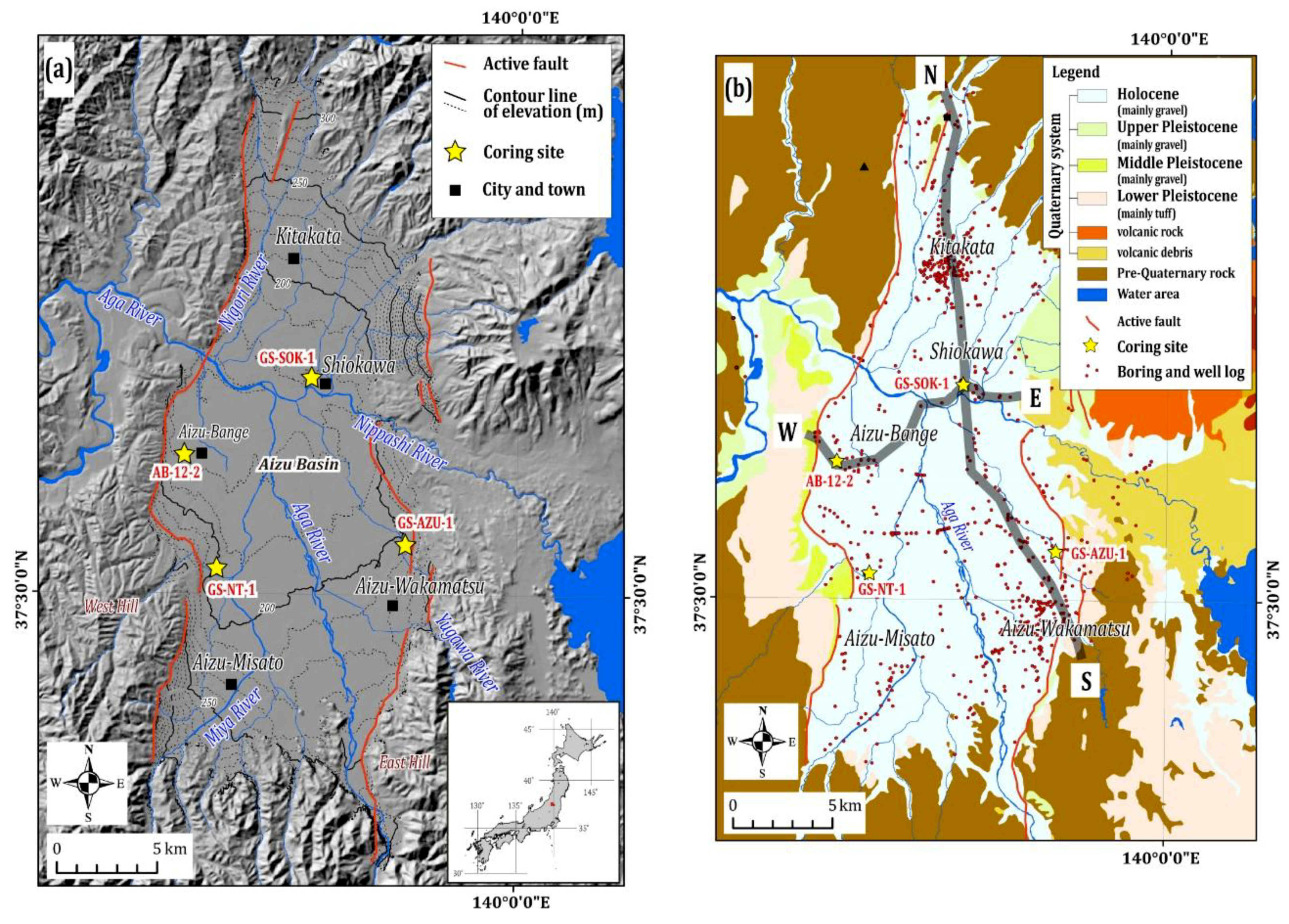
2. Study Area
3. Material and Methods
3.1. Analysis of Shallow Subsurface Geological Structure
3.2. Calculation and Mapping of Ground Effective Thermal Conductivity
4. Mathematical Formulation
5. Results
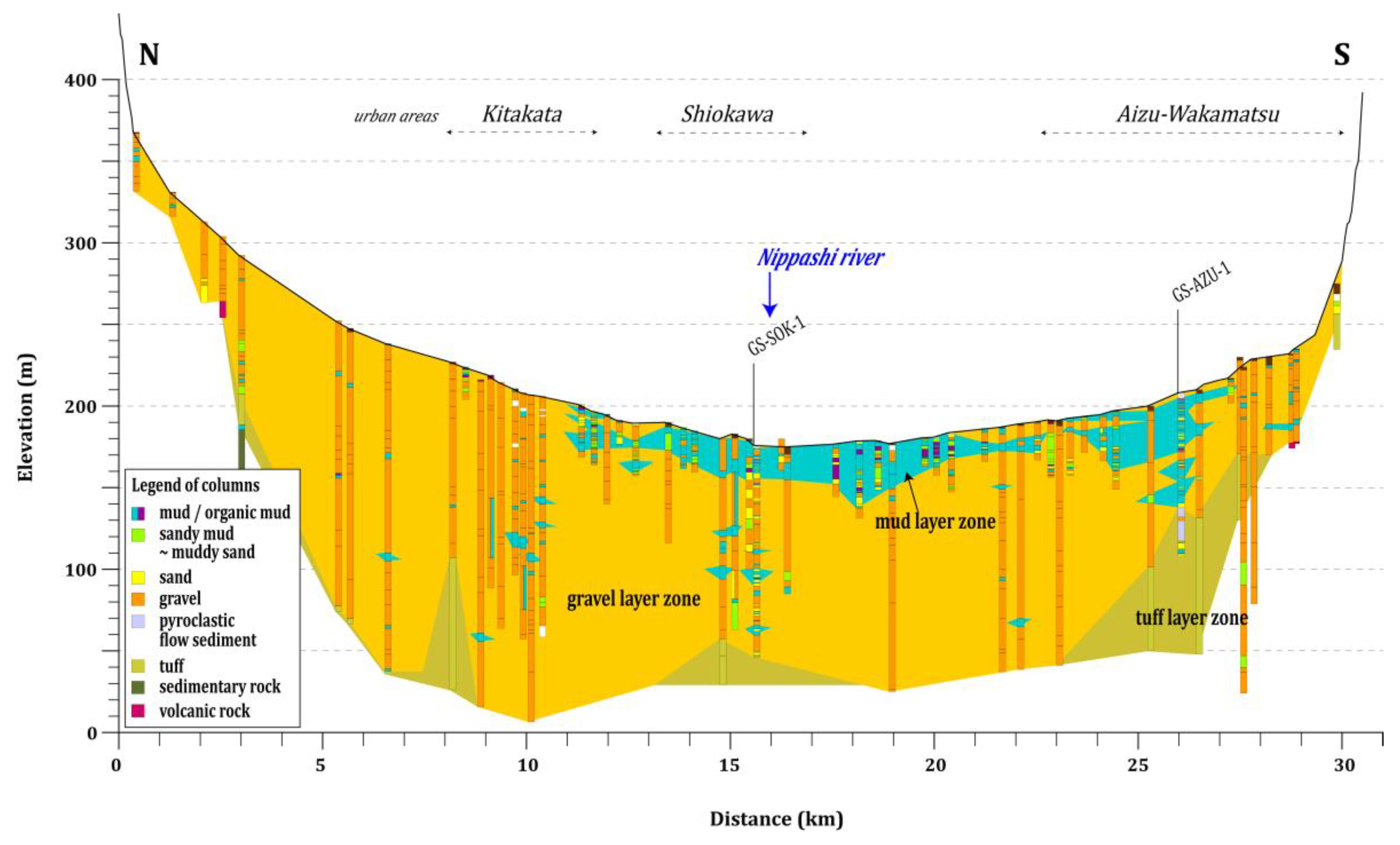
5.1. Shallow Subsurface Geological Structure
5.2. Ground Effective Thermal Conductivity Distribution Map
6. Discussion
7. Conclusions
Author Contributions
Funding
Acknowledgments
Conflicts of Interest
Nomenclature
| GHE | Ground heat exchanger |
| GSHP | Ground-source heat pump |
| 3D | three-dimensional |
| e | porosity |
| Lk | total thickness of each geological facies |
| S | moisture saturation |
| λa | thermal conductivity of air [W/m/K] |
| λave | average ground effective thermal conductivity [W/m/K] |
| λf | thermal conductivity of fluid [W/m/K] |
| λg | ground effective thermal conductivity [W/m/K] |
| λs | thermal conductivity of solid (geological facies) [W/m/K] |
References
- Fujii, H.; Inatomi, T.; Itoi, R.; Uchida, Y. Development of suitability maps for ground-coupled heat pump systems using groundwater and heat transport modeling. Geothermics 2007, 36, 459–472. [Google Scholar] [CrossRef]
- Omer, A.M. Ground-source heat pumps systems and applications. Renew. Sustain. Energy Rev. 2008, 12, 344–371. [Google Scholar] [CrossRef]
- Lund, J.W.; Boyd, T.L. Direct utilization of geothermal energy 2015 worldwide review. Geothermics 2016, 60, 66–93. [Google Scholar] [CrossRef]
- Ministry of Environment, Japan. Results of a Survey on the Use of Ground-Source Heat Pump Systems in Fiscal Year 2016. 2017. Available online: http://www.env.go.jp/press/103827 (accessed on 1 May 2018). (In Japanese).
- Uchida, Y.; Yoda, Y.; Fujii, H.; Miyamoto, S.; Yoshioka, M. Adoption of suitability area for ground-coupled heat pump systems 1st paper, Development of suitability maps for ground-coupled heat pump systems using groundwater flow/heat transport modeling and geographic information system. J. Geotherm. Res. Soc. Jpn. 2010, 32, 229–239, (In Japanese with English Abstract). [Google Scholar]
- Fujii, H.; Okubo, H.; Nishi, K.; Itoi, R.; Ohyama, K.; Shibata, K. An improved thermal response test for U-tube ground heat exchanger based on optimal fiber thermometers. Geothermics 2009, 38, 399–406. [Google Scholar] [CrossRef]
- Yoshioka, M.; Uchida, Y.; Yoda, Y.; Fujii, H.; Miyamoto, S. Adoption of suitability area for ground-coupled heat pump systems 2nd paper, Development of heat exchange rate maps using groundwater flow/heat transport modeling. J. Geotherm. Res. Soc. Jpn. 2010, 32, 241–251, (In Japanese with English Abstract). [Google Scholar]
- Nomoto, T.; Fujii, H.; Uchida, Y.; Kagabu, M.; Shimada, J. Application of geothermal heat pump systems in the warm areas from an aspect of the effect of a countermeasure against global warming. J. Geotherm. Res. Soc. Jpn. 2012, 34, 185–197, (In Japanese with English Abstract). [Google Scholar]
- Shrestha, G.; Uchida, Y.; Yoshioka, M.; Fujii, H.; Ioka, S. Assessment of development potential of ground-coupled heat pump system in Tsugaru Plain, Japan. Renew. Energy 2015, 76, 249–257. [Google Scholar] [CrossRef]
- Shrestha, G.; Uchida, Y.; Kuronuma, S.; Yamaya, M.; Katsuragi, M.; Kaneko, S.; Shibasaki, N.; Yoshioka, M. Performance evaluation of a ground-source heat pump system utilizing a flowing well and estimation of suitable areas for its installation in Aizu Basin, Japan. Hydrogeol. J. 2017, 25, 1437–1450. [Google Scholar] [CrossRef]
- Shrestha, G.; Uchida, Y.; Ishihara, T.; Kaneko, S.; Kuronuma, S. Assessment of the installation potential of a ground source heat pump system based on the groundwater condition in the Aizu Basin, Japan. Energies 2018, 11, 1178. [Google Scholar] [CrossRef]
- Hamada, Y.; Tanaka, S.; Nagano, K.; Tamura, H.; Takigawa, I.; Nakamura, Y.; Marutani, K.; Takashimizu, Y.; Takada, M. Feasibility study of underground thermal energy system by using digital national land information. Trans. Soc. Heat. Air-Cond. Sanit. Eng. Jpn. 2009, 34, 1–10, (In Japanese with English Abstract). [Google Scholar]
- Takemura, T.; Nakazato, K.; Tajima, T.; Takano, Y. Extraction of geological conditions for ground heat utilization and the development of an independent source system utilizing heat and water power. Proc. Inst. Nat. Sci. Nihon Univ. 2014, 49, 155–162, (In Japanese with English abstract). [Google Scholar]
- Sakata, Y.; Katsura, T.; Nagano, K. A study on estimation of ground effective thermal conductivity as probability-weighted average. J. Geotherm. Res. Soc. Jpn. 2018, 40, 33–44, (In Japanese with English Abstract). [Google Scholar]
- Hamamoto, H.; Shiraishi, H.; Hachinohe, S.; Ishiyama, T.; Satake, K.; Miyakoshi, A. Synthesis of subsurface temperature information and evaluation of potential for setting up ground heat exchangers in Saitama prefecture. Butsuri-Tansa (Geophys. Explor.) 2014, 67, 107–119, (In Japanese with English Abstract). [Google Scholar] [CrossRef]
- Japan Meteorological Agency. Average Values of Meteorological Data in Wakamatsu. Available online: https://www.data.jma.go.jp/obd/stats/etrn/view/nml_sfc_ym.php?prec_no=36&block_no=47570&year=&month=&day=&view=p1 (accessed on 13 July 2018). (In Japanese)
- Aizu-Wakamatsu City. Environmental Basic Plan in Second Phase. 2014. Available online: https://www.city.aizuwakamatsu.fukushima.jp/docs/2007121100044/files/keikakuhonnpenn.pdf (accessed on 19 July 2018). (In Japanese).
- Kitakata City. Renewable Energy Vision (2017–2016) in Kitakata City. 2018. Available online: https://www.city.kitakata.fukushima.jp/uploaded/attachment/12510.pdf (accessed on 19 July 2018). (In Japanese).
- Ikeda, T.; Imaizumi, T.; Togo, M.; Hirakawa, K.; Miyauchi, T.; Sato, H. Atlas of Quaternary Thrust Faults in Japan; University of Tokyo Press: Tokyo, Japan, 2002. (In Japanese) [Google Scholar]
- Geological Survey of Japan, AIST. Seamless Digital Geological Map of Japan (1:200,000). 2015. Available online: https://gbank.gsj.jp/seamless/index_en.html (accessed on 1 May 2018).
- Suzuki, K.; Manabe, K.; Yoshida, T. The late Cenozoic stratigraphy and geologic development of the Aizu Basin, Fukushima Prefecture, Japan. Mem. Geol. Soc. Jpn. 1977, 14, 17–44, (In Japanese with English Abstract). [Google Scholar]
- Yamamoto, T.; Yoshioka, T. Geology of the Wakamatsu District. With Geological Sheet Map at 1:50,000; Geological Survey of Japan: Tsukuba, Japan, 1992; (In Japanese with English abstract).
- Yamamoto, T.; Yoshioka, T; Makino, M.; Sumita, T. Geology of the Kitakata District. Quadrangle Series, 1:50,000; Geological Survey of Japan, AIST: Tsukuba, Japan, 2006; (In Japanese with English abstract).
- Kaneko, R.; Nakagawa, S. Water balance in Aizu Basin. Bull. Natl. Res. Inst. Agric. Eng. Jpn. 1969, 7, 33–51, (In Japanese with English Abstract). [Google Scholar]
- Kaneko, S.; Shibasaki, N.; Shoji, M.; Uchida, Y. Characteristics of changes in groundwater level and groundwater temperature based on long-term monitoring in the Aizu Basin, Fukushima, Japan. Bull. Geol. Surv. Jpn. 2016, 67, 183–208, (In Japanese with English Abstract). [Google Scholar] [CrossRef]
- Akimoto, T.; Suzuki, Y. Water quality of confined groundwater in the Aizu Basin, Fukushima Prefecture. Jpn. Assoc. Hydrol. Sci. 1988, 18, 14–21, (In Japanese with English Abstract). [Google Scholar]
- Ishihara, T.; Suzuki, T.; Hongo, M.; Uchida, Y. Study of shallow subsurface geology based on analysis of sedimentary cores drilled in the Aizu Basin, Northeast Japan. Presented at the Japan Geoscience Union and American Geophysical Union Meeting, Chiba, Japan, 20–25 May 2017. [Google Scholar]
- Suzuki, T.; Saito, H.; Kasahara, A.; Kuriyama, E.; Imaizumi, T. Late Quaternary tephrostratigraphy of underground sediments in the middle west part of Aizu Basin, Fukushima, northeast Japan. Quat. Res. (Daiyonki-Kenkyu) 2016, 55, 1–16, (In Japanese with English Abstract). [Google Scholar] [CrossRef]
- Ishihara, T.; Suzuki, T.; Hongo, M.; Uchida, Y. Geological stratigraphy of a drilling core based on analysis of tephras and pollen assemblages in the western part of Aizu Basin, Northeast Japan. Presented at the Japan Geoscience Union Meeting, Chiba, Japan, 20–24 May 2018. [Google Scholar]
- Diersch, H.J.G. FEFLOW Reference Manual; WASY GmbH Institute for Water Resources Planning and Systems Research: Berlin, Germany, 2005. [Google Scholar]
- Diersch, H.J.G. FEFLOW: Finite Element Modeling of Flow, Mass and Heat Transport in Porous and Fractured Media; Springer: Berlin, Germany, 2014. [Google Scholar]
- Ghanbarian, B.; Daigle, H. Thermal conductivity in porous media: Percolation-based effective-medium approximation. Water Resour. Res. 2015, 52, 295–314. [Google Scholar] [CrossRef]


| Geological Facies | Porosity | Thermal Conductivity (W/m/K) | Ground Effective Thermal Conductivity (W/m/K) | |
|---|---|---|---|---|
| Saturated | Unsaturated | |||
| Top soil | 0.2 | 1.4 | 1.25 | 1.12 |
| Mud (Silt) | 0.4 | 1.4 | 1.10 | 0.85 |
| Sand | 0.35 | 1.5 | 1.20 | 0.98 |
| Gravel | 0.25 | 1.6 | 1.36 | 1.21 |
| Peat | 0.5 | 0.7 | 0.68 | 0.36 |
| Tuff (Pyroclastic flow sediments) | 0.2 | 1.0 | 0.93 | 0.80 |
| Rock | 0.15 | 2.5 | 2.22 | - |
| Water | - | 0.65 | - | - |
| Air | - | 0.024 | - | - |
© 2018 by the authors. Licensee MDPI, Basel, Switzerland. This article is an open access article distributed under the terms and conditions of the Creative Commons Attribution (CC BY) license (http://creativecommons.org/licenses/by/4.0/).
Share and Cite
Ishihara, T.; Shrestha, G.; Kaneko, S.; Uchida, Y. Analysis of Shallow Subsurface Geological Structures and Ground Effective Thermal Conductivity for the Evaluation of Ground-Source Heat Pump System Installation in the Aizu Basin, Northeast Japan. Energies 2018, 11, 2098. https://doi.org/10.3390/en11082098
Ishihara T, Shrestha G, Kaneko S, Uchida Y. Analysis of Shallow Subsurface Geological Structures and Ground Effective Thermal Conductivity for the Evaluation of Ground-Source Heat Pump System Installation in the Aizu Basin, Northeast Japan. Energies. 2018; 11(8):2098. https://doi.org/10.3390/en11082098
Chicago/Turabian StyleIshihara, Takeshi, Gaurav Shrestha, Shohei Kaneko, and Youhei Uchida. 2018. "Analysis of Shallow Subsurface Geological Structures and Ground Effective Thermal Conductivity for the Evaluation of Ground-Source Heat Pump System Installation in the Aizu Basin, Northeast Japan" Energies 11, no. 8: 2098. https://doi.org/10.3390/en11082098
APA StyleIshihara, T., Shrestha, G., Kaneko, S., & Uchida, Y. (2018). Analysis of Shallow Subsurface Geological Structures and Ground Effective Thermal Conductivity for the Evaluation of Ground-Source Heat Pump System Installation in the Aizu Basin, Northeast Japan. Energies, 11(8), 2098. https://doi.org/10.3390/en11082098