Dry Fuel Jet Half-Angle Measurements and Correlation for an Entrained Flow Gasifier †


Abstract
:1. Introduction
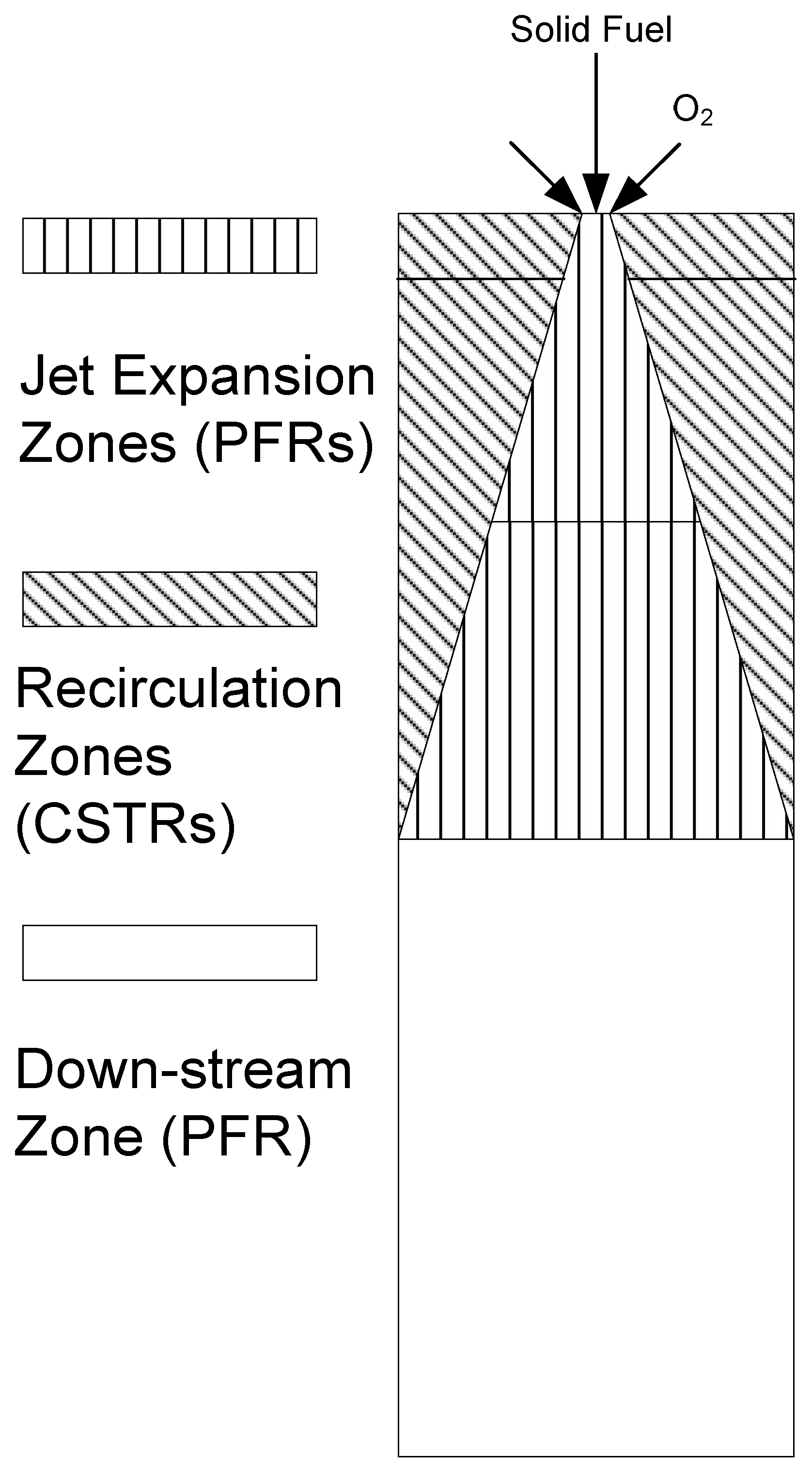
2. Theory
2.1. Previous Studies
2.2. Model Extension
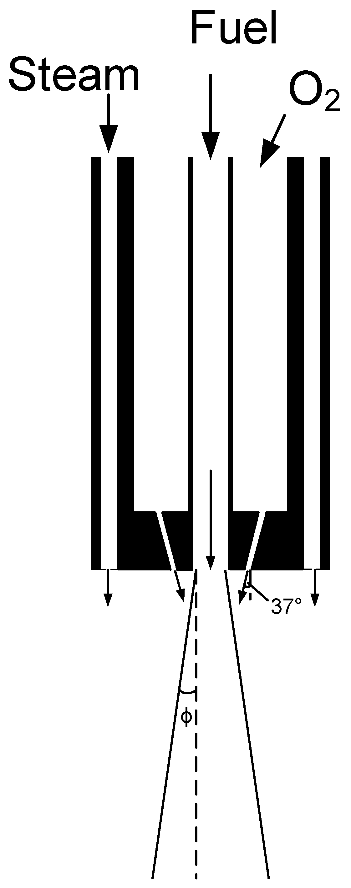
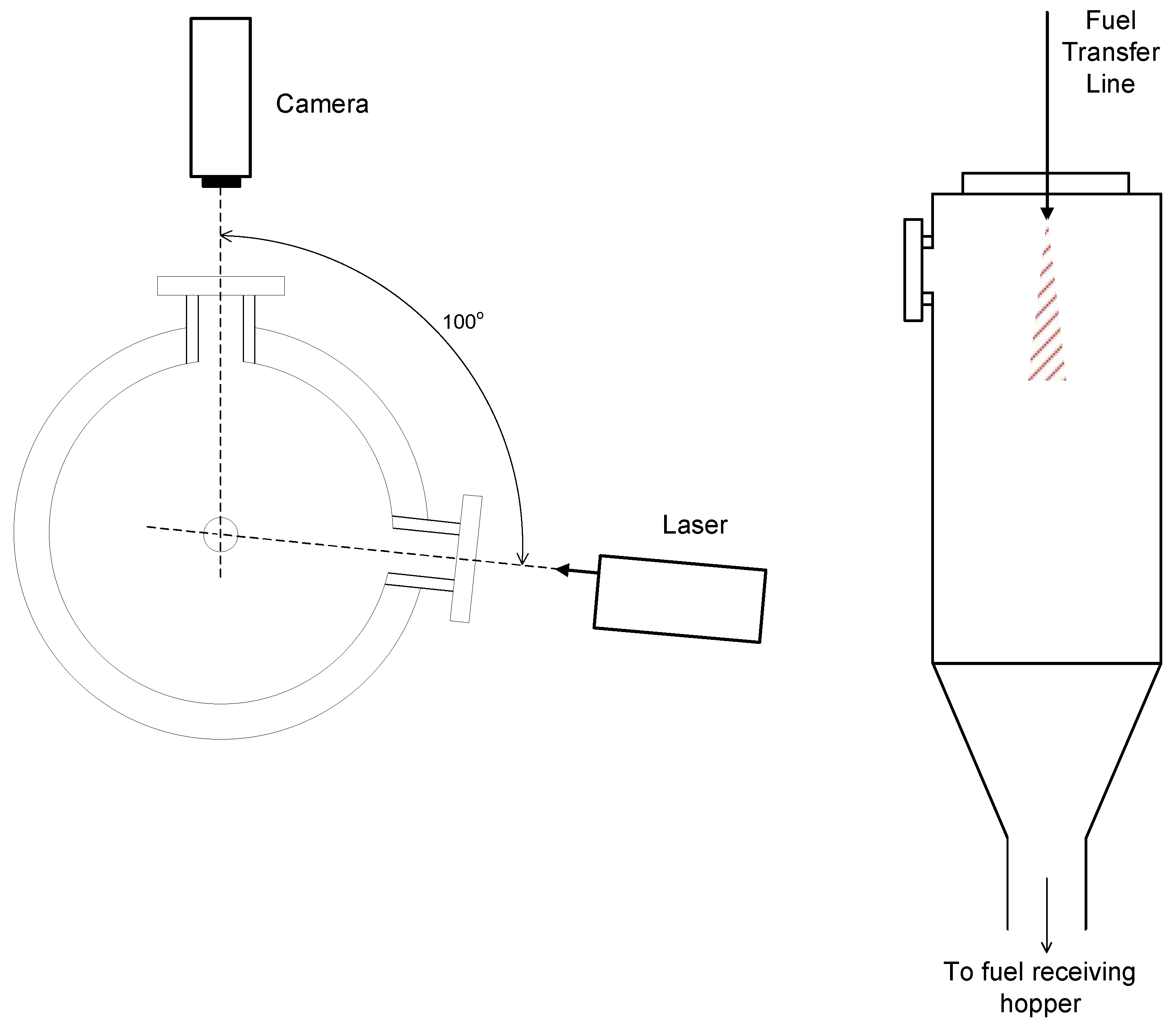
3. Experimental Setup
4. Results and Discussion
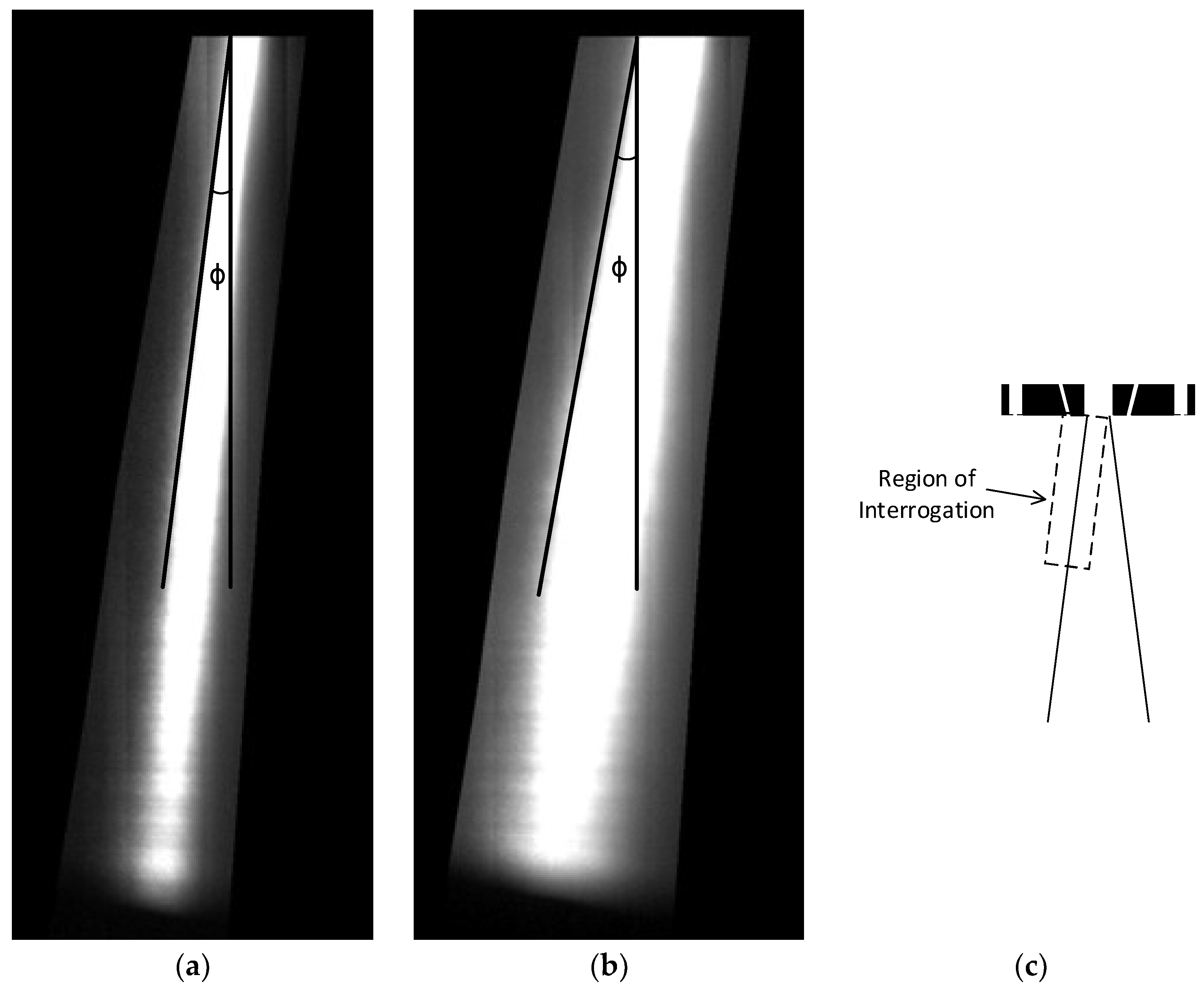
4.1. Experimental Results
4.2. Jet Half-Angle Variability
4.3. Model Fitting
5. Conclusions
Author Contributions
Funding
Acknowledgments
Conflicts of Interest
Nomenclature
| constant for Equation (2) (unitless) | |
| mass flow rate (kg/h) | |
| solid/gas loading ratio (kgsolid/kggas) |
| density (kg/m3) | |
| jet half-angle (°) |
| surroundings | |
| gas | |
| jet core at the injection point | |
| solids |
References
- International Energy Agency. CO2 Emissions from Fuel Combustion; Organization for Economic Co-operation and Development: Paris, France, 2012; ISBN 978-92-64-17475-7. [Google Scholar]
- Kunze, C.; Spliethoff, H. Assessment of oxy-fuel, pre- and post-combustion-based carbon capture for future IGCC plants. Appl. Energy 2012, 94, 109–116. [Google Scholar] [CrossRef]
- Shi, S.-P.; Zitney, S.E.; Shahnam, M.; Syamlal, M.; Rogers, W.A. Modelling coal gasification with CFD and discrete phase method. J. Energy Inst. 2006, 79, 217–221. [Google Scholar] [CrossRef]
- Fletcher, D.F.; Haynes, B.S.; Christo, F.C.; Joseph, S.D. A CFD based combustion model of an entrained flow biomass gasifier. Appl. Math. Model. 2000, 24, 165–182. [Google Scholar] [CrossRef]
- Sahraei, M.H.; Duchesne, M.A.; Yandon, R.; Majeski, A.; Hughes, R.W.; Ricardez-Sandoval, L.A. Reduced order modeling of a short-residence time gasifier. Fuel 2015, 161, 222–232. [Google Scholar] [CrossRef]
- Sahraei, M.H.; Duchesne, M.A.; Hughes, R.W.; Ricardez-Sandoval, L.A. Dynamic reduced order modeling of an entrained-flow slagging gasifier using a new recirculation ratio correlation. Fuel 2017, 196, 520–531. [Google Scholar] [CrossRef]
- Monaghan, R.F.D.; Ghoniem, A.F. A dynamic reduced order model for simulating entrained flow gasifiers: Part I: Model development and description. Fuel 2012, 91, 61–80. [Google Scholar] [CrossRef]
- Sahraei, M.H.; Yandon, R.; Duchesne, M.A.; Hughes, R.W.; Ricardez-Sandoval, L.A. Parametric Analysis Using a Reactor Network Model for Petroleum Coke Gasification. Energy Fuels 2015, 29, 7681–7688. [Google Scholar] [CrossRef]
- Sahraei, M.H.; Duchesne, M.A.; Hughes, R.W.; Ricardez-Sandoval, L.A. Experimental Assessment, Model Validation, and Uncertainty Quantification of a Pilot-Scale Gasifier. Ind. Eng. Chem. Res. 2016, 55, 6961–6970. [Google Scholar] [CrossRef]
- Monaghan, R.F.D. Dynamic Reduced Order Modeling of Entrained Flow Gasifiers. PhD Thesis, Massachusetts Institute of Technology, Cambridge, MA, USA, 2010. [Google Scholar]
- Hedman, P.O.; Smoot, L.D. Particle-gas dispersion effects in confined coaxial jets. AIChE J. 1975, 21, 372–379. [Google Scholar] [CrossRef]
- Modaress, D.; Elghobashi, S.; TAN, H. Two-component LDA measurement in a two-phase turbulent jet. AIAA J. 1984, 22, 624–630. [Google Scholar] [CrossRef]
- Fleckhaus, D.; Hishida, K.; Maeda, M. Effect of laden solid particles on the turbulent flow structure of a round free jet. Exp. Fluids 1987, 5, 323–333. [Google Scholar] [CrossRef]
- Zhang, J.; Zhou, L. Particle behaviors in a pulverized coal-fired sudden-expansion combustor with coaxial jets. Fuel 2001, 80, 289–299. [Google Scholar] [CrossRef]
- Almeida, T.G.; Jaberi, F.A. Large-eddy simulation of a dispersed particle-laden turbulent round jet. Int. J. Heat Mass Transf. 2008, 51, 683–695. [Google Scholar] [CrossRef]
- Sijercic, M.; Belosevic, S.; Stevanovic, Z. Simulation of free turbulent particle-laden jet using Reynolds-stress gas turbulence model. Appl. Math. Model. 2007, 31, 1001–1014. [Google Scholar] [CrossRef]
- Barlow, R.S.; Morrison, C.Q. Two-phase velocity measurements in dense particle-laden jets. Exp. Fluids 1990, 9, 93–104. [Google Scholar] [CrossRef]
- Liu, H.; Cao, W.; Xu, J.; Li, W.; Guo, X.; Sun, Z. Characterization of the granular jet in a coaxial gas stream. Powder Technol. 2012, 225, 206–213. [Google Scholar] [CrossRef]
- Ranz, W.E. Some experiments on orifice sprays. Can. J. Chem. Eng. 1958, 36, 175–181. [Google Scholar] [CrossRef]
- Reitz, R.D.; Bracco, F.V. Ultra-high-speed filming of atomizing jets. Phys. Fluids 1979, 22, 1054–1064. [Google Scholar] [CrossRef]
- Wu, K.-J.; Su, C.-C.; Steinberger, R.L.; Santavicca, D.A.; Bracco, F.V. Measurements of the Spray Angle of Atomizing Jets. J. Fluids Eng. 1983, 105, 406–413. [Google Scholar] [CrossRef]
- Roy, A.; Segal, C.; Joly, C. Spreading Angle and Core Length Analysis of Supercritical Jets. AIAA J. 2013, 51, 2009–2014. [Google Scholar] [CrossRef]
- Beér, J.M.; Chigier, N.A. Combustion Aerodynamics; Krieger Publishing Company: Malabar, FL, USA, 1983; ISBN 978-0-89874-545-0. [Google Scholar]
- Kus, F.T.; Duchesne, M.A.; Champagne, S.; Hughes, R.W.; Lu, D.Y.; Macchi, A.; Mehrani, P. Pressurized pneumatic conveying of pulverized fuels for entrained flow gasification. Powder Technol. 2016, 287, 403–411. [Google Scholar] [CrossRef]
- Daviault, S.G.; Ramadan, O.B.; Matida, E.A.; Hughes, P.M.; Hughes, R. Atomization performance of petroleum coke and coal water slurries from a twin fluid atomizer. Fuel 2012, 98, 183–193. [Google Scholar] [CrossRef]
- Duchesne, M.A.; Champagne, S.; Hughes, R.W. Dry petroleum coke gasification in a pilot-scale entrained-flow gasifier and inorganic element partitioning model. Energy Fuels 2017, 31, 6658–6669. [Google Scholar] [CrossRef]
- Macchi, A.; Bi, H.; Grace, J.R.; McKnight, C.A.; Hackman, L. Dimensional hydrodynamic similitude in three-phase fluidized beds. Chem. Eng. Sci. 2001, 56, 6039–6045. [Google Scholar] [CrossRef]
- Runstedtler, A.; Yandon, R.; Duchesne, M.; Hughes, R.; Boisvert, P. Conversion of Petroleum Coke in a High-Pressure Entrained-Flow Gasifier: Comparison of Computational Fluid Dynamics Model and Experiment. Energy Fuels 2017, 31, 5561–5570. [Google Scholar] [CrossRef]
- Sauriol, P.; Cui, H.; Chaouki, J. Gas–solid structure in the vicinity of a sparger nozzle in a fluidized bed. Powder Technol. 2012, 228, 131–140. [Google Scholar] [CrossRef]

| Condition Number | Solid Flow (kg/h) | N2 Gas Flows (kg/h) | Pressure (kPa) | Loading Ratio (kgsolid/kggas) | Jet Half-Angle (°) | ||
|---|---|---|---|---|---|---|---|
| Conveying | Impinging | Sleeve | |||||
| 1 | 81 | 4.7 | 0 | 0 | 1600 | 17.34 | 5.6 ± 0.1 |
| 2 | 95 | 6.2 | 0 | 0 | 1600 | 15.26 | 5.9 ± 0.2 |
| 3 | 84 | 5.7 | 0 | 0 | 1600 | 14.75 | 6.1 ± 0.1 |
| 4 | 74 | 5.1 | 0 | 0 | 1600 | 14.61 | 6.0 ± 0.1 |
| 5 | 62 | 7.8 | 0 | 0 | 1600 | 7.98 | 6.4 ± 0.2 |
| 6 | 71 | 9.7 | 0 | 0 | 1600 | 7.32 | 6.4 ± 0.2 |
| 7 | 54 | 7.9 | 0 | 0 | 1600 | 6.85 | 6.7 ± 0.2 |
| 8 | 27 | 7.4 | 0 | 10 | 800 | 3.65 | 8.9 ± 0.2 |
| 9 | 25 | 7.5 | 0 | 0 | 800 | 3.33 | 10.0 ± 0.2 |
| 10 | 69 | 9.6 | 40 | 10 | 1600 | 1.39 | 11.3 ± 0.2 |
| 11 | 53 | 8.7 | 40 | 0 | 1600 | 1.09 | 11.3 ± 0.1 |
| 12 | 52 | 9.4 | 40 | 10 | 1600 | 1.05 | 11.3 ± 0.1 |
| 13 | 50 | 8.7 | 40 | 10 | 1600 | 1.03 | 11.1 ± 0.1 |
| Condition Number | 4 | 6 | 10 | 11 | 13 |
|---|---|---|---|---|---|
| solid/gas loading ratio a | 14.6 | 7.3 | 7.2 | 6.1 | 5.7 |
| solid/gas loading ratio b | 14.6 | 7.3 | 1.4 | 1.1 | 1.0 |
| impinging gas (kg/h) | 0 | 0 | 40 | 40 | 40 |
| sleeve gas (kg/h) | 0 | 0 | 10 | 0 | 10 |
| mean jet half-angle (°) | 5.9 | 6.2 | 9.4 | 10.2 | 9.8 |
| half-angle standard deviation (°) | 0.6 | 0.6 | 1.0 | 1.1 | 1.1 |
| half-angle coefficient of variation | 0.10 | 0.10 | 0.11 | 0.11 | 0.11 |
| Case | Solid Flow (kg/h) | Gas Flows (kg/h) | Loading Ratio | Surrounding Temperature (K) | CFD Half-Angle a (°) | Equation (2) Half-Angle (°) | ||
|---|---|---|---|---|---|---|---|---|
| Carrier N2 | Impinging O2 | Sleeve H2O | ||||||
| 1 | 41 | 8.2 | 37.2 | 10.7 | 0.90 | 1231 | 3.6–5.2 | 5.1 |
| 2 | 60 | 7.5 | 43.6 | 10.2 | 1.17 | 1165 | 4.6–6.7 | 4.9 |
© 2018 by Kus, Macchi, Mehrani and Her Majesty the Queen. Licensee MDPI, Basel, Switzerland. This article is an open access article distributed under the terms and conditions of the Creative Commons Attribution (CC BY) license (http://creativecommons.org/licenses/by/4.0/).
Share and Cite
Kus, F.; Hughes, R.; Macchi, A.; Mehrani, P.; Duchesne, M. Dry Fuel Jet Half-Angle Measurements and Correlation for an Entrained Flow Gasifier. Energies 2018, 11, 1967. https://doi.org/10.3390/en11081967
Kus F, Hughes R, Macchi A, Mehrani P, Duchesne M. Dry Fuel Jet Half-Angle Measurements and Correlation for an Entrained Flow Gasifier. Energies. 2018; 11(8):1967. https://doi.org/10.3390/en11081967
Chicago/Turabian StyleKus, Francis, Robin Hughes, Arturo Macchi, Poupak Mehrani, and Marc Duchesne. 2018. "Dry Fuel Jet Half-Angle Measurements and Correlation for an Entrained Flow Gasifier" Energies 11, no. 8: 1967. https://doi.org/10.3390/en11081967
APA StyleKus, F., Hughes, R., Macchi, A., Mehrani, P., & Duchesne, M. (2018). Dry Fuel Jet Half-Angle Measurements and Correlation for an Entrained Flow Gasifier. Energies, 11(8), 1967. https://doi.org/10.3390/en11081967