Article

Research into the Energy Output of Asymmetric Cylindrical Structure under Internal Explosion Loading

College of Liberal Arts and Sciences, National University of Defense Technology, Changsha 410073, China
*
Author to whom correspondence should be addressed.
Energies 2018, 11(4), 967; https://doi.org/10.3390/en11040967
Submission received: 26 February 2018 / Revised: 11 April 2018 / Accepted: 14 April 2018 / Published: 18 April 2018

Abstract

:
The energy output characteristic of an asymmetric cylindrical structure under internal explosion loading has significant research value in the field of the national defense industry. This paper took the D-shaped structure as the research object. Three groups of experiments (D-90°, D-120°, D-150°) were carried out. The D-shaped structure showed that fragments are concentrated in the middle and are sparse on both sides. Moreover, the fragment density decreased with the increase of the azimuth angle. The fragment velocities, which were measured from high-speed photography and an oscilloscope, coincided well with each other, and decreased with an increase in the central angle. Compared with the cylindrical structure, the fragment energy gain of the D-shaped structure is significant; the total energy and energy density of the three D-shaped structures were very close to each other. This indicates that D-120° is the optimal solution among the three D-shaped structures and it can provide guidance for the future design of D-shaped structures to achieve higher energy output.

1. Introduction

Cylindrical casing is a very important and common structure in engineering applications. In the national defense industry, cylindrical casing has always been regarded for a carrier of weapons. Due to its axisymmetric structure, the fragments fly outward along the radial in a uniform distribution under internal explosion loading, which leads to poor damage efficiency in the target direction. A lot of significant research on fragment dispersion and fragment velocity distribution about the fragment generators has been reported. Wang et al. [1] proposed a formula to quickly predict the radial velocity distribution of fragments of the Velocity Enhanced Warhead, and the correction function applied to the formula took into account the directionality and initiation characteristics of fragments. Dhote et al. [2] carried out several experiments to study the spatial dispersion of fragments in two configurations of fragment generator warhead (FGWs), and the results showed that the projection angles had a normal distribution. Lian et al. [3] utilized the MPM (material point method) to simulate the explosively driven metal problems, and a new correction function to the Gurney solution was put forward, which considered the lateral effects for the flat sandwich configuration. Huang et al. [4] and Wang et al. [5] have all researched the fragment velocity distribution of cylindrical casings under eccentric point initiation. The explosive experiments were conducted with pulsed X-ray diagnostics, and the formula derived from experimental data can achieve fast computation of fragment velocity distributions. In addition, many researchers have also tried to work on how to improve the energy output and the utilization rate of fragments. The earliest prototype of deformable cylindrical structure [6] was reported in 1973. Held [7] put forward a concept about the deformable cylindrical structure in 1992, which immediately received wide attention. Fairlie et al. [8] and Racah et al. [9] first carried out numerical analysis on the deformation of a deformable cylindrical structure and the process of fragment dispersion by using Autodyn-3D, which is widely used to simulate explosive loading [10,11]. Bonorchis et al. [12,13] studied the structural response of rectangular plates under different explosive loading conditions from the perspective of simulation, and the simulation method adopted is worth learning. The casing profile plays an important role in the design of a deformable cylindrical structure. Li et al. [14] conducted some experiments for the deformation shape of cylindrical casing with an internal medium under lateral explosion loading. Gefken et al. [15] studied the damage efficiency of cylindrical casing subjected to partial explosion loading by using an energy analysis method. Hoo Fatt et al. [16] and Wierzbicki et al. [17] reported the plastic damage effects of cylindrical casing under lateral impact loading. Yakupov [18,19] reported the dynamic response of cylindrical casings under a planar plastic shock wave by using the rigid plastic hinge theory.
Based on the above literature, researchers have undertaken a lot of work regarding the deformable cylindrical structure. To the best of our knowledge, there is relatively little research on the influence of the profile on the energy output. The asymmetric cylindrical structure can be roughly divided into three types: the concave-shaped, convex-shaped, and D-shaped. The research on concave-shaped and convex-shaped types has been described in another article [20]. Therefore, this paper mainly focuses on the D-shaped structure, and several experiments were carried out to investigate the influence of the central angle on the spatial distribution, fragment velocity and energy output. The final discussions can provide guidance for the design of a D-shaped structure to achieve a higher energy output.

2. Experiments

Three D-shaped devices were manufactured for experiments; the schematic diagrams and sizes of D-shaped devices are shown in Figure 1. The central angles of the D-shaped device are 150°, 120°, and 90°, respectively. In the following content, D-150°, D-120°, and D-90° were used to represent the three D-shaped structures. Each device contains four parts: upper endplate, lower endplate, D-shaped casing, and explosive. The material properties of the four parts are listed in Table 1. In order to display the interior of the structure, the casing part of Figure 1a is not fully displayed. More details of experiments are given in the following sections.

2.1. Specimen

The D-shaped explosive made of TNT, with a nominal diameter of 100 mm and height of 80 mm, is detonated from the top. The D-shaped casing consists of a major arc part and a rectangular part, and the two parts were peripherally welded. The inner diameter, the thickness and the height of the above two parts are 100 mm, 4.8 mm, and 80 mm, as shown in Figure 1. The sizes of the upper and lower endplates are identical, the diameter and height of which are 109.6 mm and 10 mm, respectively. The D-shaped casing and the endplates were connected by screws. To control the rupture positions and the size of fragments, the rectangular plates were pre-grooved by using a wire cutting process, as shown in Figure 2. The characteristic dimensions of the pre-grooves were 4.8 mm in width, 3.8 mm in depth (along the axial direction), 4.8 mm in depth (along the circumferential direction). The assembly drawing of three D-shaped devices is shown in Figure 2.

2.2. Experimental Arrangement

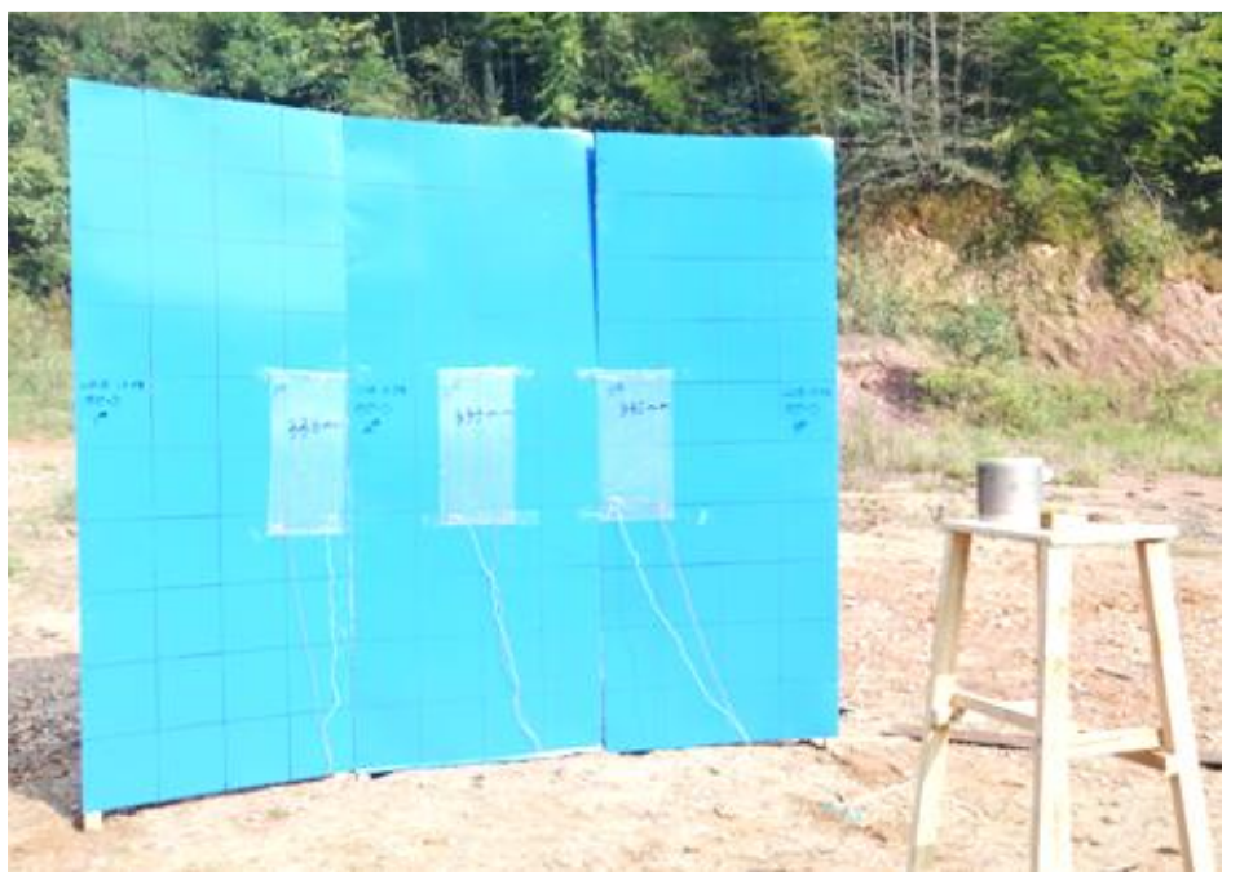
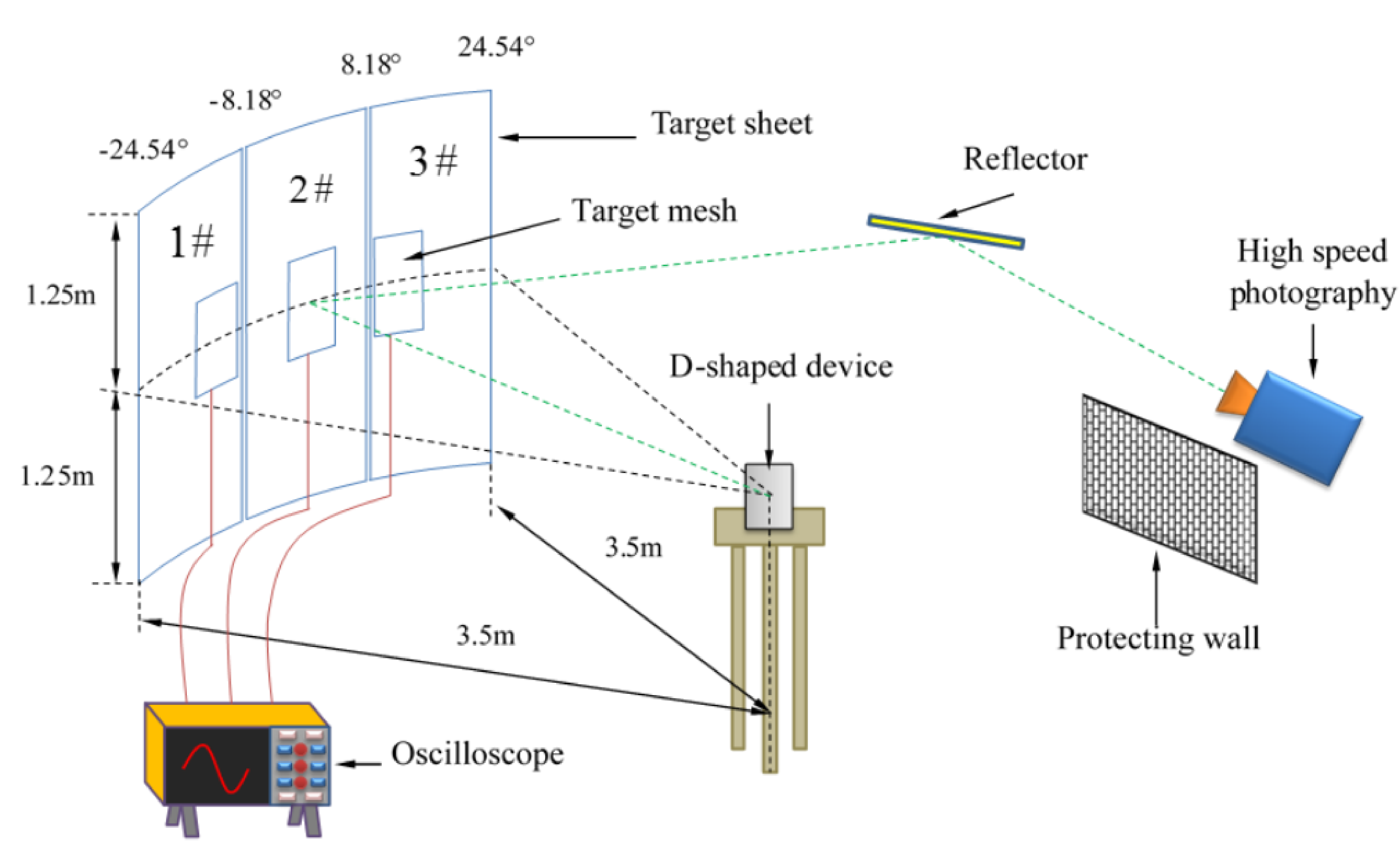
The target plates made of steel, with a width of 1 m, a height of 2.5 m, and a thickness of 0.3 mm, were placed in the opposite end of the D-shaped device to record the spatial distribution of fragments, as shown in Figure 3. The plate was divided into several square areas (25 cm × 25 cm) by gridlines. The distance between the D-shaped device and target plate was 3.5 m, so the angle of each grid was 4.09°. Each target plate, numbered 1#, 2#, 3# clockwise, was labeled a target mesh to measure the fragment velocity. The axis of the D-shaped device was vertical to the ground, and the rectangular plate of the D-shaped device faced the center of the 2# target plate. Only under these conditions can we obtain the spatial distribution of fragments in theory.
In the experiment, high-speed photography and an oscilloscope were used to measure the arrival time of the fragment. The time measurement principle of an oscilloscope is based on the change of the voltage signal. When the cased explosive explodes, the wire wound around the device is blown off, the corresponding channel is changed from short circuit to open circuit, and the corresponding voltage changes from 0 V to 5 V. In other words, a voltage take-off signal will be recorded by one channel of the oscilloscope, corresponding to the moment t0. Similarly, when the fragment impacts the target plate, the wire in the target mesh is also broken, and another oscilloscope channel will also record a voltage take-off signal (0 V to 5 V), corresponding to the moment t1. As a result, the flight time ∆t of the fragment is t0t1. The time measurement principle of high-speed photography aims to extract the time points on the video. A reflector was placed between the target plate and the high-speed photography, with the camera lens aimed at the center of the 2# target plate. In order to protect the high-speed photography from fragment damage, a protective wall was established beside the high-speed photography, as shown in Figure 4. For the following analysis, it is assumed that the direction from the center of the D-shaped device to the center of the 2# target plate is the 0° azimuth angle. It is important to note that the azimuth angle is positive along the clockwise direction.

3. Typical Experimental Results

The experimental results are discussed and presented in two parts: (1) the spatial distribution of fragments; and (2) the fragment velocity. The details of the two aspects are described in detail in the following sections, respectively.

3.1. Results on the Spatial Distribution of Fragments

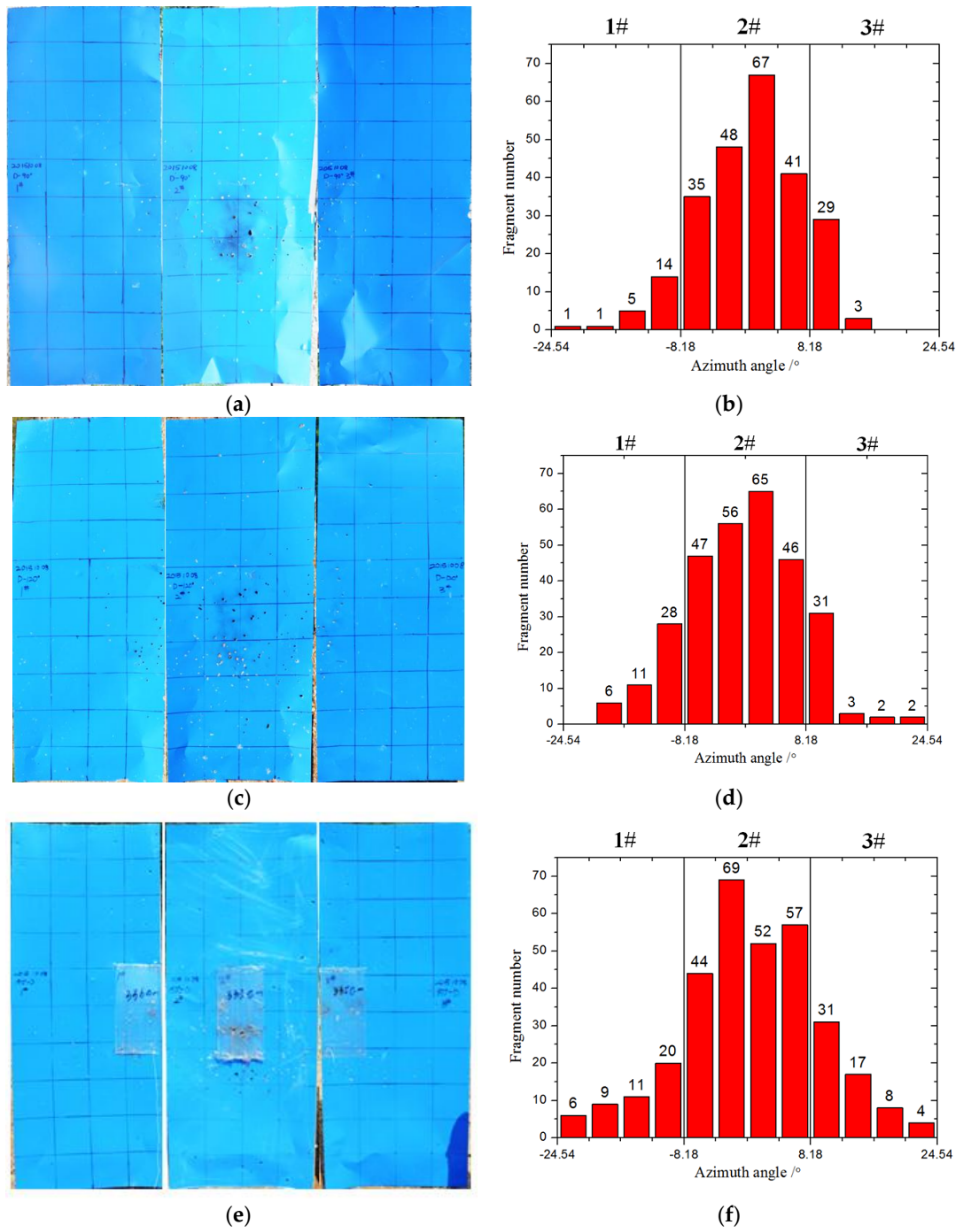
The rectangular plate was torn into lots of fragments under the action of the detonation wave, and then the fragments flew into the air at high speed. The spatial distribution of fragments can reflect the damage power of the D-shaped structure, so observing the interception results of target plates is an effective way to research the dispersion of fragments.
The interception result and statistics of fragments are shown in Figure 5. To analyze with ease, the initial number of fragments was defined as N0; the total number of recovered fragments is N1, which is determined by the number of perforations on the target plate; the number of recovered fragments in −8.18°–8.18° azimuth angle range is N2. The initial number of fragments N0 can be calculated according to the size of the fragment, the gap between the fragments, and the width and height of the plate. The relationships between N0, N1, and N2 are listed in Table 2.

3.2. Results on the Fragment Velocity

The high-speed photography record from D-90° and D-120° is shown in Figure 6 and Figure 7, respectively. The two figures respectively show the corresponding moments when the fragments impact different numbered target plates after the explosion, as listed in the fifth column of Table 3 and Table 4 (the time when the device exploded is t = 0 ms). In addition, the image of Figure 7 is darker, because the frame rate of Figure 7 is higher than the frame rate of Figure 6. The purpose of doing this is to highlight the flare produced by the fragment when it impacts the target plate, making it easier to determine the time of fragment impact on the target plate. Due to some unknown problems that arose in the experiment, the experimental data of D-150° was not saved. Despite the lack of D-150°, the data obtained from D-90° and D-120°could still show the dispersion rules of fragments.
Based on the distance between the D-shaped device and target plate, as well as the arrival time, the average velocity of fragments was calculated and the initial velocity of fragments could also be derived by aerodynamic theory. The fragment velocities of D-90° and D-120° are listed in Table 3 and Table 4, respectively. The experiments involved in this paper are all explosion tests. Because the time of the explosion process is very short and there are many uncertain factors in the experimental process, it inevitably leads to measurement errors. From Table 3 and Table 4, it can be seen that the fragment velocities obtained by the oscilloscope and the high speed photography are in good agreement with each other, except that the errors corresponding to a very few groups are slightly larger. After analysis, the main sources of error include distance measurement, reading of the corresponding time of the take-off points of the oscilloscope, determination of the time of the fragment impacting the target in high-speed photography, selection of the frame frequency of high-speed photography, etc. The above factors cause the final fragment velocity error.

4. Analysis of Experimental Results

The spatial distribution and velocity distribution of fragments play important roles in energy output, so it is necessary to analyze their mechanism. The spatial distribution of fragments was obtained from the reclaimed target plates, and the fragment velocity was obtained from the high-speed photography and oscilloscope. The following analysis is based on the statistical results of Section 3.1 and Section 3.2, which indicates the influence of the central angle.

4.1. Effect of Central Angle on the Spatial Distribution of Fragments

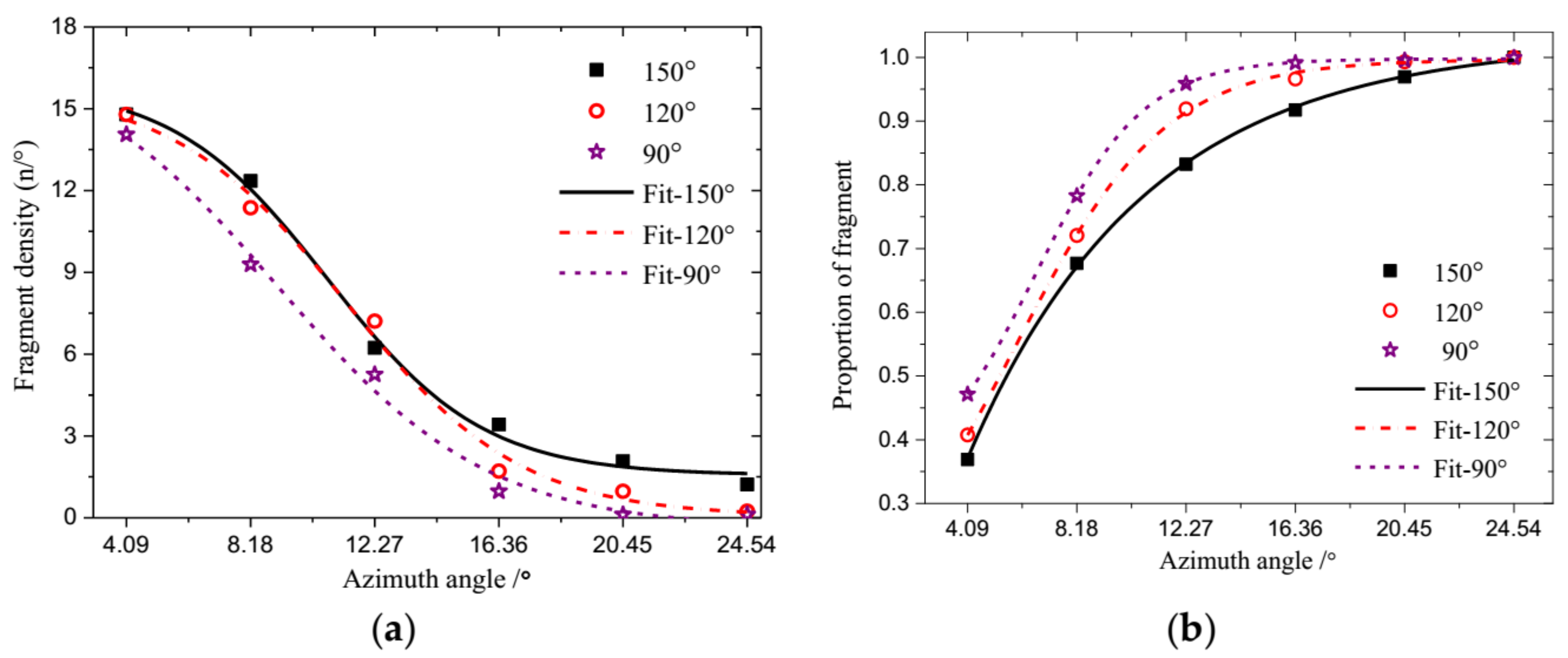
Based on the statistical number of fragments in Section 3.1, the fragment density and the proportion of fragments were obtained. The relationships between fragment density and azimuth angle were fitted by using the Boltzmann distribution, as shown in Figure 8a. The relationships between proportion of fragment and azimuth angle were fitted by using the polynomial distribution, as shown in Figure 8b.
Figure 8a shows that the fragment densities of the three D-shaped structures have the same pattern, namely that the fragment density decreases with an increase in azimuth angle. The fragment density of the three D-shaped devices is almost the same in the 4.09° azimuth angle. The fragment density of D-120° is closer to the D-150°, so the fragment density does not change significantly when the central angle is larger than 120°. The fragment densities of D-120° and D-150° are larger than D-90°, because the initial number of fragments of D-120° and D-150° is larger than that of D-90°. However, D-150° is smaller than D-120° in the 12.27° azimuth angle range, which may result in the statistical errors.
The relationship between the proportion of fragments and azimuth angle is shown in Figure 8b. The proportion of the three D-shaped structures increases with the increase of azimuth angle and the growth rate of the proportion gradually decreases, because the distribution of the fragments is dense in the middle and sparse on both sides. In addition, the initial fragment number of D-90° is the lowest among the three D-shaped structures, so the proportion of D-90° is larger than the D-120° and D-150° structures.

4.2. Effect of Central Angle on the Fragment Velocity

Fragments obtained their initial velocity under the action of the detonation wave. Hereafter, they were affected by the gravity and air resistance when flying in the air: the gravity caused the fragment trajectory to bend downwards and the air resistance caused the fragment velocity to decrease with the increase of flight distance. Due to the short flight distance and high speed, the influence of gravity is negligible and can be ignored. It is assumed that the fragment trajectory is a straight line and the air resistance is the main influential factor. In engineering, the velocity attenuation coefficient α is defined to reflect the ability to maintain velocity during flight. The expression of coefficient α is expressed as follows.
α = S × C D × ρ α 2 m f
S = φ × m f 2 / 3
where S is the frontal area of fragment, CD is the aerodynamic drag coefficient, ρ α is the material density, mf is the fragment mass, ϕ is the fragment shape factor.
Substituting Formula (2) into Formula (1), the expression of coefficient α becomes
α = φ × C D × ρ β 2 m f 1 / 3
The parameter values of the cubic fragment are listed in Table 5. Substituting the parameter values into Formula (3), the velocity attenuation coefficient α is 0.0246/m.
According to reference [21], the velocity attenuation formula of the fragment in the air is expressed as follows
v = v 0 e α x
where v is the instantaneous velocity, v0 is the initial velocity, α is the velocity attenuation coefficient, x is the distance between the fragment and D-shaped device, e is the power exponent.
Integrating the Formula (4), the relation between the initial velocity v0 and the average velocity v ¯ is as follows
v 0 = v ¯ α x 1 e α x
The nominal distance between the target plate and the D-shaped device is 3.5 m, i.e., the value of x is 3.5 m. Substituting the values of α and x into Formula (5), it can be simplified to the following expression
v 0 = v ¯ × 1.043
As described above in this paper, Table 3 and Table 4 show the fragment average velocity results from the oscilloscope and high-speed photography. Based on Formula (6), the initial velocity was obtained, as shown in Table 6 and Table 7.
It can be seen from Table 6 and Table 7, that the fragment velocity decreases with the increase of azimuth angle, because the detonation wave has a relatively long propagation distance before imparting onto the fragments for the large azimuth angle. Due to the effective explosive mass of D-90° being larger than D-120°, the fragment velocity resulting from D-90° is higher than D-120° at the same azimuth angle. The maximum fragment velocity from D-90° is 1871 m/s, and its counterpart from D-120° is 1767 m/s at 0° azimuth angle.

4.3. The Effect of the Central Angle on the Energy of Fragments

The spatial distribution and fragment velocity were obtained, as mentioned in Section 3.1 and Section 3.2. According to the kinetic energy theorem, the energy distribution on the target plates was counted out, and the total energy of fragments in the α azimuth angle is expressed as
E α = i = 1 j m v α i 2 2
where j is the total number of fragments in α azimuth angle range, vαi is the velocity of No. i fragment in α azimuth angle, m is the fragment mass.
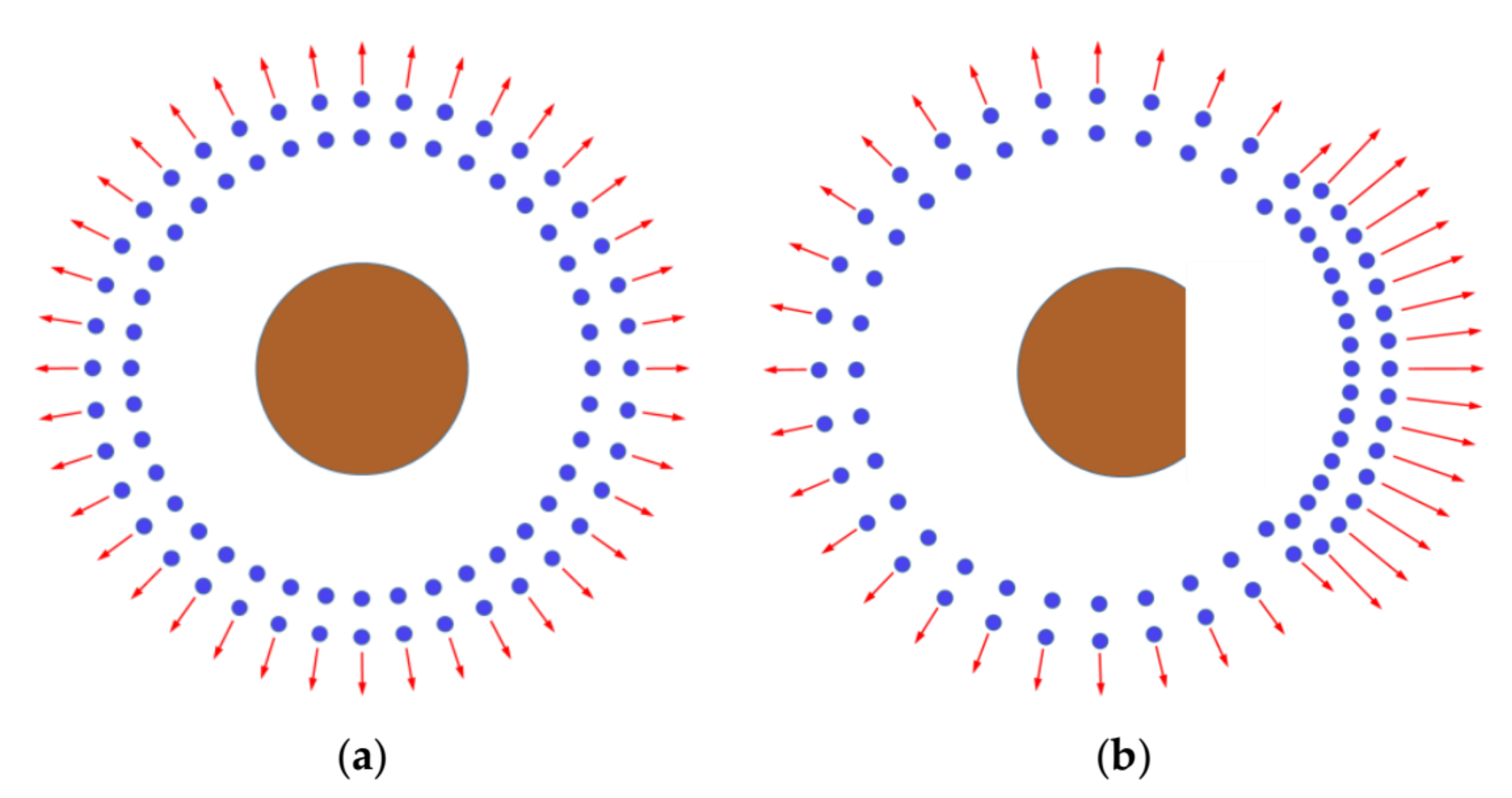
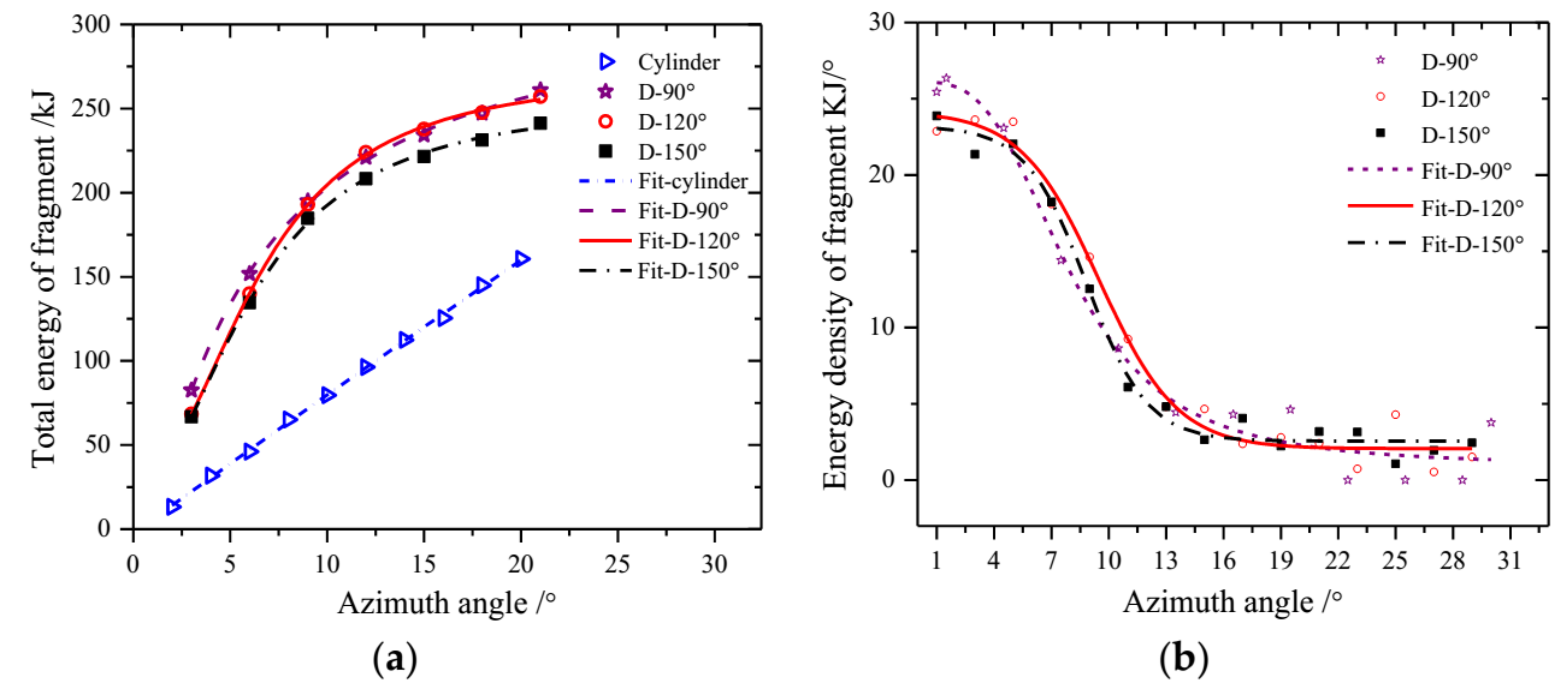
In order to facilitate comparison and analysis, the traditional cylindrical casing scored with the same pattern as the D-shaped casing was also tested, and the data of the cylindrical casing was used as the basic contrast data. The schematic diagram of the spatial distribution and velocity distribution of fragments, corresponding to the cylindrical fragment generator and the D-shaped fragment generator after the explosion of internal explosive, is shown in Figure 9. As can be seen from Figure 9, the spatial distribution and velocity distribution of the fragments produced by the cylindrical fragment generator are uniform in the circumferential direction, while the spatial distribution and velocity distribution of the fragments produced by the D-shaped fragment generator in the circumferential direction are both non-uniform. In the region facing the D-shaped surface, the fragments are denser and the fragment velocity is higher. After statistical calculation, the energy distribution of the fragments is shown in Figure 10a. In the 0°–30° azimuth angle range, the total energy of fragments was counted within each 2° azimuth angle and then divided by the interval width of 2°. The energy density distribution of the fragment was obtained, as shown in Figure 10b.
Compared with the cylindrical structure, the fragment energy gain of the D-shaped structure is significant, as shown in Figure 9a. Figure 9 shows that the fitting curves of the three D-shaped structures have a consistent pattern of variation within the acceptable range of error, but that the total energy and energy density of D-90° and D-120° structures are higher than D-150°. The mass is a very important factor for the structure design. The explosive mass of the D-shaped structure decreases as the central angle increases, which leads to the mass of the whole structure decreasing. In other words, the mass of D-90° is larger than D-120°, the reduction of the D-shaped structure mass can increase the effective mass of other components, which is beneficial in engineering applications. Based on the above analysis, D-120° is the optimal solution.
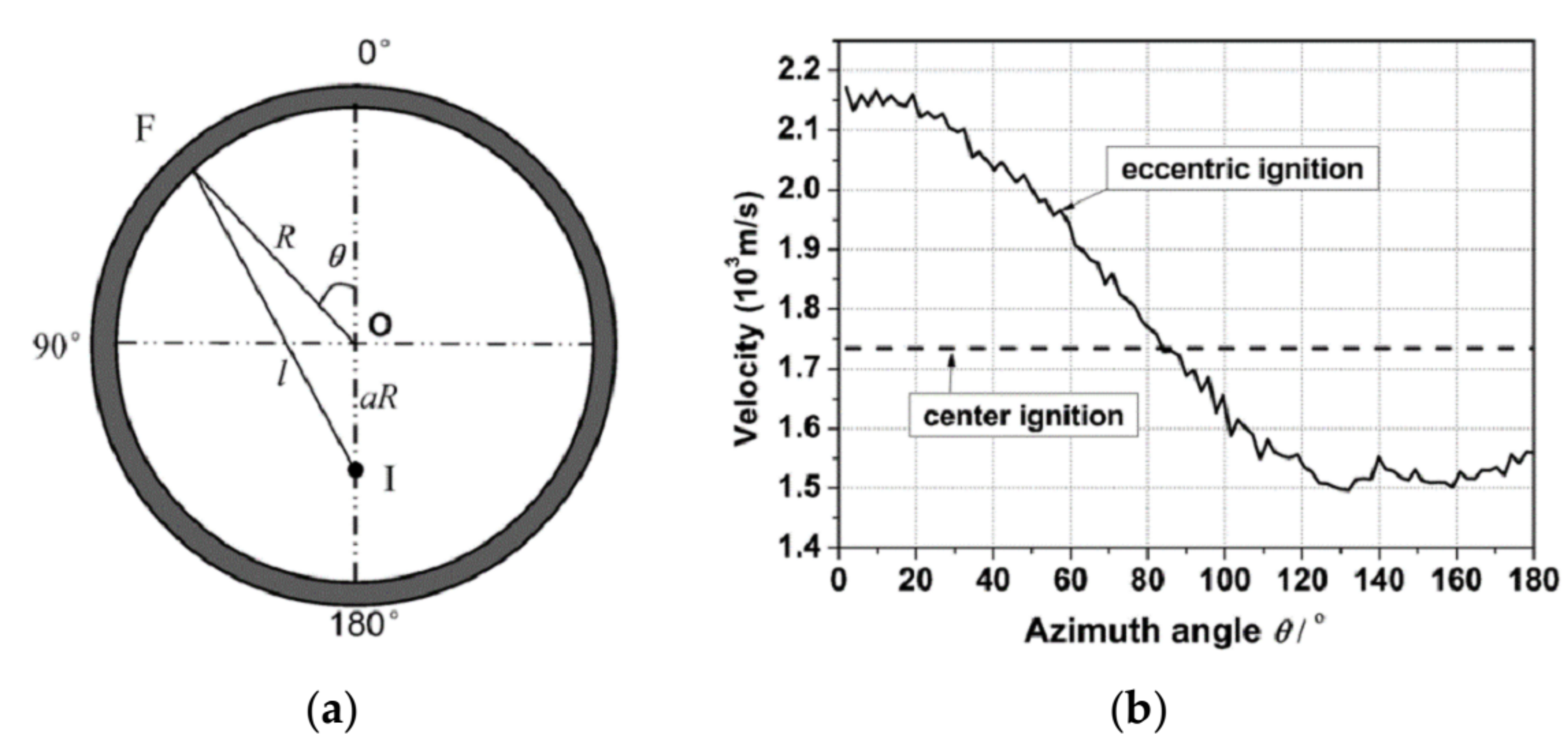
Moreover, the rule that changing the initiation point can improve the damage effectiveness of the warhead can be found in reference [1]. From reference [1], the schematic diagram of the eccentric ignition of the cylindrical warhead is shown in Figure 11a, and the velocity curve of fragments under eccentric ignition and center ignition is shown in Figure 11b. As shown in Figure 11b, fragment velocity decreases with the increase of azimuth angle under the condition of eccentric ignition and it is obvious that the fragment velocity is enhanced at the azimuth angle from 0° to about 85°. In view of this, the D-shaped structure can also use eccentric ignition to further improve the damage performance of the fragments, which will have a significant impact on the direction of the development of our future research.

5. Conclusions

In this paper several experiments were carried out to study the energy output of a D-shaped structure. The central angle of a D-shaped structure was proven to be the main influencing factor. The spatial distribution of a fragment was obtained from the impacting position on target plates. The spatial distribution characteristic of the D-shaped structure is that the fragments are concentrated in the middle and are sparse on both sides, and the fragment density decreases with the increase of azimuth angle. The fragment velocity was obtained from high-speed photography, which agreed with the results obtained from an oscilloscope. The fragment velocity decreases as the central angle increases because the explosive mass decreases as the central angle of the D-shaped structure increases. The maximum fragment velocities of D-90° and D-120° are 1871 m/s, 1767 m/s, respectively. The fragment energy gain of the D-shaped structure is significant, and the total energy and energy density of the D-90° and D-120° structures are higher than D-150°. The explosive mass of the D-shaped structure decreases as the central angle increases, the reduction of the D-shaped structure mass can compensate for the effective mass of the other components (MD-90° > MD-120° > MD-150°), which is beneficial in engineering applications. Therefore, the D-120° structure is optimal and eccentric ignition can be used to further improve the damage effectiveness of fragments for our coming research. The conclusions of this work can provide guidance for the future design of D-shaped structures.

Acknowledgments

This work was financially supported by the National Natural Science Foundation of China (No. 11202237 and 11132012). The financial contributions are gratefully acknowledged.

Author Contributions

Liangliang Ding put forward the research ideas of this article, designed the experiments, and wrote the article. Zhenduo Li participated in the experiments, and was responsible for the collection of experimental data. Fangyun Lu and Xiangyu Li analyzed the experimental results, and revised the article.

Conflicts of Interest

The authors declare no conflict of interest.

References

  1. Wang, M.; Lu, F.; Li, X.; Cao, L. A formula for calculating the velocities of fragments from velocity enhanced warhead. Propellants Explos. Pyrotech. 2013, 38, 232–237. [Google Scholar] [CrossRef]
  2. Dhote, K.; Murthy, K.; Rajan, K.; Sucheendran, M. Statistics of fragment dispersion by explosion in a fragment generator warhead. Cent. Eur. J. Energ. Mater. 2016, 13, 183–197. [Google Scholar] [CrossRef]
  3. Lian, Y.; Zhang, X.; Zhou, X.; Ma, S.; Zhao, Y. Numerical simulation of explosively driven metal by material point method. Int. J. Impact Eng. 2011, 38, 238–246. [Google Scholar] [CrossRef]
  4. Huang, G.; Li, W.; Feng, S. Fragment velocity distribution of cylindrical rings under eccentric point initiation. Propellants Explos. Pyrotech. 2015, 40, 215–220. [Google Scholar] [CrossRef]
  5. Wang, L.; Han, F.; Chen, F. Fragment velocity distribution of velocity enhanced warhead under double symmetric initiations. Propellants Explos. Pyrotech. 2016, 41, 672–681. [Google Scholar] [CrossRef]
  6. Parker, L. Directed Warhead. U.S. Patent 3,714,897, 6 February 1973. [Google Scholar]
  7. Held, M. Aimable fragment warhead. In Proceedings of the 13th International Symposium on Ballistics (ISB ′14), Stockholm, Swedish, 1–3 June 1992. [Google Scholar]
  8. Fairlie, G.; Marriott, C.; Robertson, N.; Livingstone, I.; Birnbaum, N. Computer modelling of full size fragmenting aimable warheads using Autodyn-3D. In Proceedings of the 17th International Symposium on Ballistics (ISB ’17), Midrand, South Africa, 23–27 March 1998. [Google Scholar]
  9. Racah, E.; Binenboim, E.; Peleg, G. 3D Simulations of aimable fragmentation warheads. In Proceedings of the 15th International Symposium on Ballistics (ISB ’15), Jerusalem, Israel, 21–24 May 1995. [Google Scholar]
  10. Balden, V.; Nurick, G. Numerical simulation of the post-failure motion of steel plates subjected to blast loading. Int. J. Impact Eng. 2005, 32, 14–34. [Google Scholar] [CrossRef]
  11. Luccioni, B.; Ambrosini, D.; Danesi, R. Blast load assessment using hydrocodes. Eng. Struct. 2006, 28, 1736–1744. [Google Scholar] [CrossRef]
  12. Bonorchis, D.; Nurick, G. The influence of boundary conditions on the loading of rectangular plates subjected to localised blast loading—Importance in numerical simulations. Int. J. Impact Eng. 2009, 36, 40–52. [Google Scholar] [CrossRef]
  13. Bonorchis, D.; Nurick, G. The analysis and simulation of welded stiffener plates subjected to localised blast loading. Int. J. Impact Eng. 2010, 37, 260–273. [Google Scholar] [CrossRef]
  14. Li, X.; Li, Z.; Liang, M. An analytical approach for deformation shapes of a cylindrical shell with internal medium subjected to lateral contact explosive loading. Math. Probl. Eng. 2015, 2015, 563097. [Google Scholar] [CrossRef]
  15. Gefken, P.; Kirkpatrick, S.; Holmes, B. Response of impulsively loaded cylindrical shells. Int. J. Impact Eng. 1988, 7, 213–227. [Google Scholar] [CrossRef]
  16. Fatt, M.; Wierzbicki, T. Damage of plastic cylinders under localized pressure loading. Int. J. Mech. Sci. 2012, 33, 999–1016. [Google Scholar] [CrossRef]
  17. Wierzbicki, T.; Fatt, M. Damage assessment of cylinders due to impact and explosive loading. Int. J. Impact Eng. 1993, 13, 215–241. [Google Scholar] [CrossRef]
  18. Yakupov, R. Plastic strains in a cylindrical shell under the effect of a spherical blast wave. Strength Mater. 1982, 14, 52–56. [Google Scholar] [CrossRef]
  19. Yakupov, R. Plastic deformations of a cylindrical shell under the action of a planar explosion wave. J. Appl. Mech. Tech. Phys. 1982, 23, 579–584. [Google Scholar] [CrossRef]
  20. Ding, L.; Li, Z.; Liang, M.; Li, X.; Lu, F. The dispersion rule of fragments about the asymmetric shell. Shock Vib. 2017, 2017, 9810978. [Google Scholar] [CrossRef]
  21. Li, X.; Liang, M.; Wang, M.; Lu, G.; Lu, F. Experimental and Numerical Investigations on the Dynamic Fracture of a Cylindrical Shell with Grooves Subjected to Internal Explosive Loading. Propellants Explos. Pyrotech. 2015, 39, 723–732. [Google Scholar] [CrossRef]
Figure 1. Schematic diagram and sizes of D-shaped devices. (a) D-90°; (b) D-120°; (c) D-150°.
Energies 11 00967 g001
Figure 2. Assembly drawing of three different D-shaped devices. (a) D-90°; (b) D-120°; (c) D-150°.
Energies 11 00967 g002
Figure 3. Sketch of the overall experimental arrangement.
Energies 11 00967 g003
Figure 4. Schematic diagram of experimental arrangement.
Energies 11 00967 g004
Figure 5. Interception situation of target plate and the related statistics of fragments. (a) Interception situation of D-90°; (b) fragment statistics of D-90°; (c) interception situation of D-120°; (d) fragment statistics of D-120°; (e) interception situation of D-150°; (f) fragment statistics of D-150°.
Energies 11 00967 g005
Figure 6. High-speed photography record of the D-90° experiment I. (a) 2# target plate (t = 1.87 ms); (b) 3# target plate (t = 2.13 ms); (c) 1# target plate (t = 2.27 ms).
Energies 11 00967 g006
Figure 7. High-speed photography record of the D-120° experiment I. (a) 2# target plate (t = 1.96 ms); (b) 3# target plate (t = 2.20 ms); (c) 1# target plate (t = 2.24 ms).
Energies 11 00967 g007
Figure 8. Relationships between the fragment density, proportion of fragment and azimuth angle. (a) Fragment density vs. azimuth angle; (b) proportion of fragment vs. azimuth angle.
Energies 11 00967 g008
Figure 9. Schematic diagram of the spatial distribution and velocity distribution of fragments corresponding to the cylindrical fragment generator and the D-shaped fragment generator after the explosion of the internal explosive. (a) Cylindrical fragment generator; (b) D-shaped fragment generator.
Energies 11 00967 g009
Figure 10. Relationships between the total energy of fragment, energy density of fragment and azimuth angle. (a) Total energy of fragment vs. azimuth angle; (b) energy density of fragment vs. azimuth angle.
Energies 11 00967 g010
Figure 11. Schematic diagram of the eccentric ignition and fragment velocity curve (From the literature [1]). (a) Schematic diagram of the eccentric ignition of the cylindrical warhead; (b) velocity curve of fragments under eccentric ignition and center ignition.
Energies 11 00967 g011
Table 1. Material properties of the D-shaped structure.
PartMaterialDensity (g/cm3)Yield Stress (MPa)Young’s Modulus (GPa)Poisson’s Ratio
ExplosiveTNT1.64---
EndplateLY12 Aluminum2.78230700.29
Casing1020 Steel7.852752100.29
Table 2. Relationships between N0, N1, and N2.
SpecimenN0N1N2N1/N0N2/N1
D-90°25524419195.7%78.28
D-120°30629721497.1%72.05
D-150°34032822296.7%67.68
Table 3. Fragment velocity of D-90° experiment.
Target Plate NumberDistance (m)Test Results from Oscilloscope (m/s)Test Results from High-Speed Photography (m/s)
t (ms) v ¯ (m/s)t (ms) v ¯ (m/s)
1#3.402.414172.271500
2#3.351.917631.871794
3#3.282.016402.131540
Table 4. Fragment velocity of D-120° experiment.
Target Plate NumberDistance (m)Test Results from Oscilloscope (m/s)Test Results from High-Speed Photography (m/s)
t (ms) v ¯ (m/s)t (ms) v ¯ (m/s)
1#3.382.314702.241508
2#3.322.016601.961694
3#3.382.414082.201536
Table 5. Parameter values of the cubic fragment.
Parameterϕ (m2·kg−2/3)CDρα (kg/cm3)mf (kg)
Value3.09 × 10−31.241.2260.8726 × 10−3
Table 6. Fragment velocity corresponding to the D-90° experiment.
Target Plate NumberTest Results from Oscilloscope (m/s)Test Results from High-Speed Photography (m/s)
v ¯ (m/s)v0 (m/s) v ¯ (m/s)v0 (m/s)
1#1417147815001565
2#1763184017941871
3#1640171115401606
Table 7. Fragment velocity corresponding to the D-120° experiment.
Target Plate NumberTest Results from Oscilloscope (m/s)Test Results from High-Speed Photography (m/s)
v ¯ (m/s)v0 (m/s) v ¯ (m/s)v0 (m/s)
1#1470153315081574
2#1660173216941767
3#1408146915361603