Article

Spar-Type Vertical-Axis Wind Turbines in Moderate Water Depth: A Feasibility Study

1
Department of Mechanical and Structural Engineering and Materials Science, University of Stavanger, 4036 Stavanger, Norway
2
Aker Solutions AS, 1366 Lysaker, Norway
3
Department of Marine Technology, CeSOS and AMOS, Norwegian University of Science and Technology, 7491 Trondheim, Norway
4
Key Laboratory of Hydraulic Engineering Simulation and Safety, Tianjin University, Tianjin 300072, China
*
Author to whom correspondence should be addressed.
Energies 2018, 11(3), 555; https://doi.org/10.3390/en11030555
Submission received: 10 February 2018 / Revised: 28 February 2018 / Accepted: 1 March 2018 / Published: 5 March 2018

Abstract

:
The applications of floating vertical-axis wind turbines (VAWTs) in deep water have been proposed and studied by several researchers recently. However, the feasibility of deploying a floating VAWT at a moderate water depth has not yet been studied. In this paper, this feasibility is thoroughly addressed by comparing the dynamic responses of spar-type VAWTs in deep water and moderate water depth. A short spar VAWT supporting a 5 MW Darrieus rotor at moderate water depth is proposed by following the deep spar concept in deep water. A fully coupled simulation tool, SIMO-RIFLEX-DMS code, is utilized to carry out time domain simulations under turbulent wind and irregular waves. Dynamic responses of the short spar and deep spar VAWTs are analyzed and compared, including the natural periods, wind turbine performance, platform motions, tower base bending moments, and tension of mooring lines. The statistical characteristics of the thrust and power production for both spars are similar. The comparison of platform motions and tower base bending moments demonstrate a good agreement for both spars, but the short spar has better performance in surge/sway motions and side–side bending moments. The 2P response dominates the bending moment spectra for both spars. A significant variation in tension of Mooring Line 1 and a larger corresponding spectrum value are found in the short spar concept. The results indicate that the application of short spar VAWTs is feasible and could become an alternative concept at moderate water depth.

1. Introduction

The demand for and development of global wind power energy have both significantly increased in the past decades. Wind power can be captured and converted into electricity through the use of wind turbines. Wind turbines are mainly classified into horizontal-axis wind turbines (HAWTs) and vertical-axis wind turbines (VAWTs) with regard to the direction of the rotating axis. As the aerodynamic efficiency of HAWTs is generally better than that of VAWTs, nowadays the application of HAWTs with higher commercial values is mainstream in the wind energy industry.
Since greater wind resources and potential could be explored in deeper seas, wind farms are moving towards deep water in recent years. Floating offshore wind turbines have become an available solution which could be widely used in deep water. Spar, semisubmersible, and tension-leg platform (TLP)—which have been utilized in the oil and gas industry for a long time—are three primary types of floating structures for offshore wind turbines. The dynamic responses of these floating structures in the presence of the marine environment are crucial for their design purpose. The natural period of a floater is a critical index to represent its dynamic behavior. Typically, a spar is characterized by small heave motion, and its natural periods in surge/sway are usually higher than 100 s [1]. Additionally, several prototypes of floating HAWTs have been developed, such as a catenary moored spar in the Hywind project in Norway, a semisubmersible in the WindFloat demo in Portugal, and a spar-type floating wind turbine in Japan’s Minister of Environment (MOE) project at Kabashima [2]. A commercial floating wind farm, i.e., the Hywind Scotland by Statoil, started production in 2017. The feasibility of spar-type HAWTs at different water depths has been studied by Karimirad and Moan [3,4]. Their research indicates that the short spar HAWT in moderate water depth exhibits good performance in dynamic responses and maintains almost the same power production as the deep spar HAWT in deep water.
Floating VAWTs are a promising alternative to floating HAWTs due to their potential for cost-of-energy reduction and maintenance. Additionally, the structural scalability and the heavier components at the base of the structure allow a bigger rotor diameter for the VAWT to capture more energy. For the evolution of rotor size, floating VAWTs are more competitive. However, the development of floating VAWTs is still at an early stage. Some floating VAWT concepts have been proposed to explore their feasibility, such as a spar buoy with a two-bladed Darrieus rotor in the DeepWind project [5], and a Spinwind-1 prototype with a helical Darrieus rotor and a floater from the Gwind project [6], etc. Moreover, the DeepWind project was later extended for further investigation to include a 5 MW baseline rotor and an optimized blade design with less weight and higher stiffness [7,
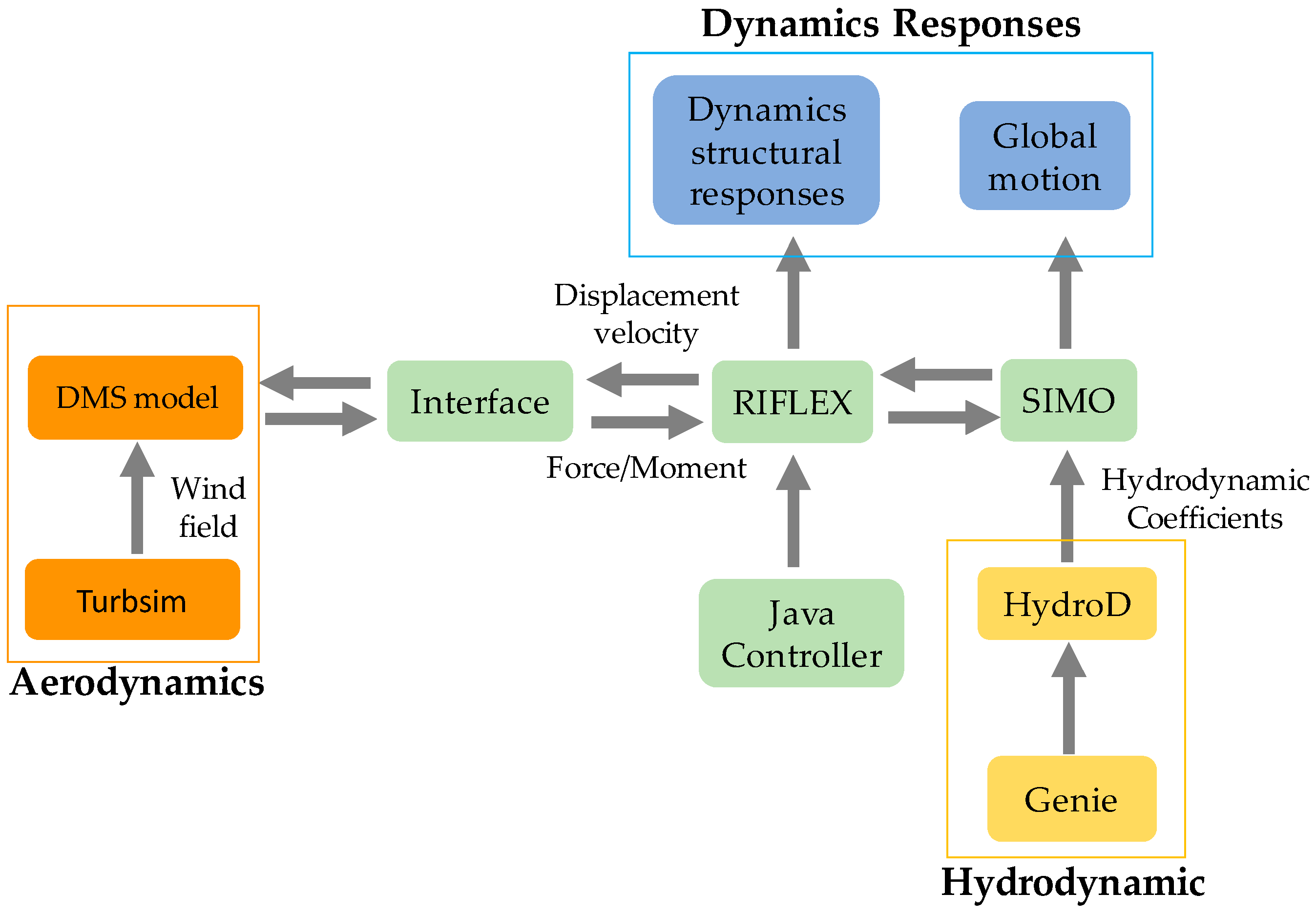
8]. Several researchers have contributed mass efforts to floating VAWT studies in deep water conditions. Wang developed a fully coupled method (SIMO-RIFLEX-DMS code) for dynamic analysis and applied it to a semisubmersible VAWT [9]. Cheng developed another fully integrated method for VAWT numerical modeling (SIMO-RIFLEX-AC code), and studied the dynamic response for various concepts, such as the dynamic analysis of spar, TLP, and semisubmersible VAWTs, etc. [10]. Ugochukwu analyzed the structural dynamic responses of a 5 MW baseline floating VAWT and a 5 MW optimized floating VAWT with the DeepWind Darrieus rotor under steady and turbulent wind conditions [11]. Liu et al. presented a motion study of a 5 MW floating VAWT composed of a truss spar floating foundation with heave plates under decay tests, wind only, regular wave and wind, and irregular wind and wave cases [12]. Overall, most of the available floating VAWT concepts have been evaluated in deep water, whereas the feasibility of deploying a floating VAWT at a moderate water depth has not yet been discussed.
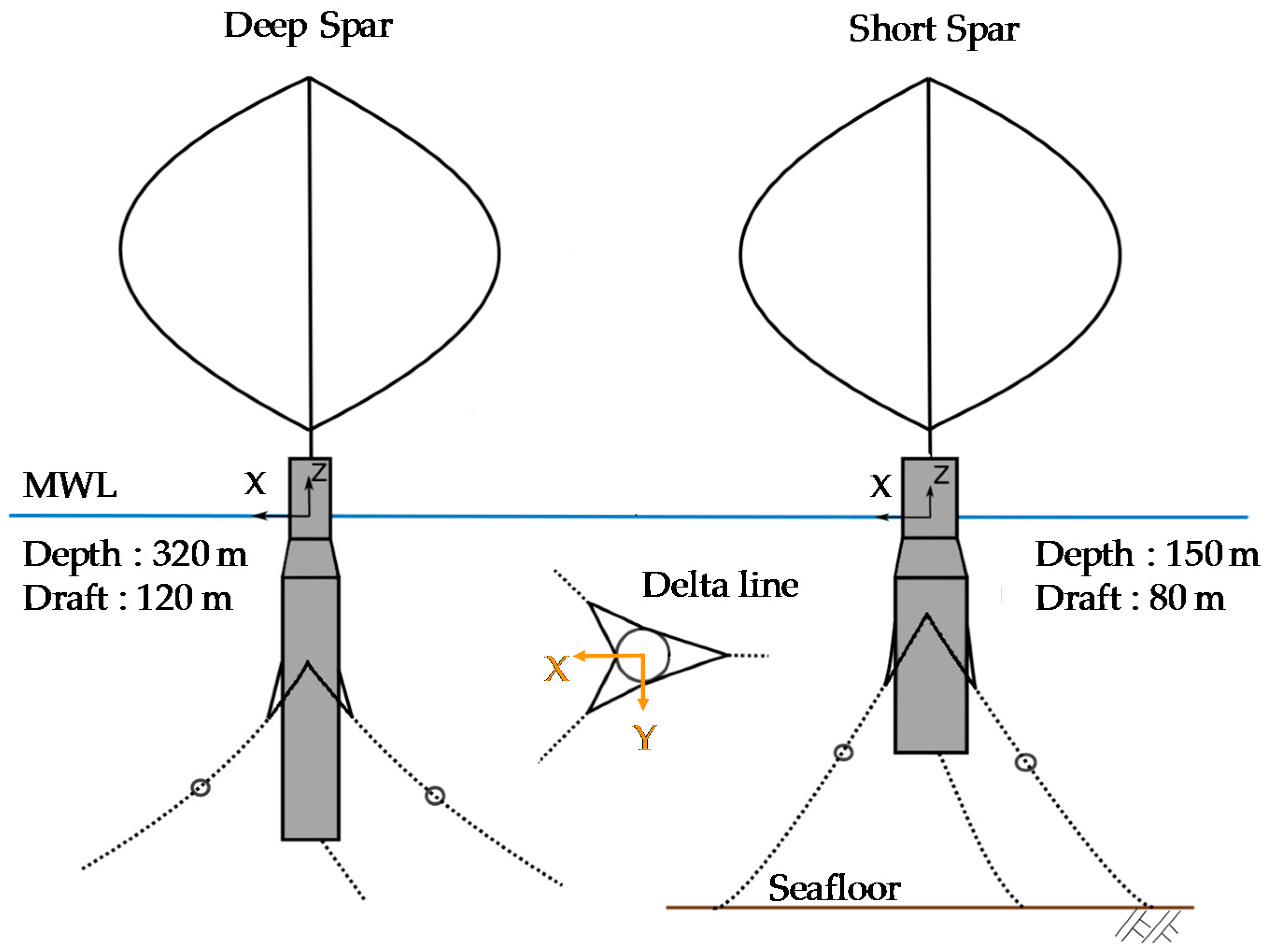
In this paper, a short spar VAWT with catenary mooring lines carrying a 5 MW Darrieus rotor in a moderate water depth (150 m) is proposed by following the deep spar concept. The methodology and modeling for both the spar VAWTs are introduced in Section 2. The dynamic response of the spar-type structure with the VAWT is analyzed through the fully coupled SIMO-RIFLEX-DMS code. Various combinations of irregular wind and wave for operating conditions are utilized to assess the response and performance of both the spar VAWTs. Section 3 presents dynamic response analysis of the short spar and deep spar VAWTs. The power performances for both the spar VAWTs are compared and evaluated. A comparative study of platform motions, tower base bending moments, and tension of mooring lines between the short spar VAWT in moderate water and deep spar VAWT in deep water is discussed. Finally, a summary of this study is shown in Section 4. The feasibility of the short spar concept in moderate water conditions is addressed.

2. Methodology and Modeling

2.1. Specifications of Deep Spar and Short Spar VAWTs

A comparison of dynamic responses between the deep spar VAWT and short spar VAWT is studied in this paper. The schematic layouts of the deep spar and short spar model are shown in Figure 1. A Darrieus 5 MW wind turbine is used for both models, and its specifications are listed in Table 1. The deep spar VAWT is a feasible concept of a catenary moored spar-type VAWT which was introduced by Cheng et al. [13]. The model of the short spar VAWT mainly follows the concept of the spar HAWT from Karimirad and Moan [3,4], but most of details have been modified. The floater of the short spar VAWT consists of two different parts of cylinders, and heavy ballast is placed on the bottom. The dimension of the short spar and configuration of the ballast are determined through the following criteria: (a) the water depth; (b) the static equilibrium of the self-weight, buoyancy force, and the tension of mooring; and (c) the typical requirement of the initial stability.
Table 2 lists the properties of the deep spar and short spar VAWTs, respectively. In principle, the water depth could limit the application of the spar in shallow water conditions. At a moderate water depth, the draft needs to be reduced so that it can achieve an adequate design. The short spar model shows that its depth is reduced to 80 m, but the diameter is increased to maintain the relevant displacement and buoyancy with the deep spar. The total mass (structural and ballast) of the short spar is 1.1% heavier than that of the deep spar. The variation of the depth of the short spar leads to a smaller mass moment of inertia in the roll and pitch directions, but the wider diameter causes a larger mass momentum in the yaw direction.
The spread mooring system includes three sets of mooring lines connected with the fairlead position of the spar structure. Each mooring line has four segments which are the two delta lines, upper line, clump mass, and lower line. The delta lines can provide yaw stiffness. The water depth will govern the total length of the mooring lines. Generally, the stiffness of the mooring line in moderate water depth is stronger than that in deep water. The properties of the mooring components follow Cheng et al. [13], and the length of the mooring line in the short spar is shortened to find a sufficient design for moderate water depth. Figure 2 illustrates the layout of the mooring system for both the deep spar and short spar VAWTs. The properties of each component in the mooring system for both spar models are listed in Table 3.

2.2. Coupled Method for Spar VAWTs

A fully coupled simulation tool (SIMO-RIFLEX-DMS) was adopted for dynamic analysis in the time domain of the spar-type VAWTs. The flow chart is shown in Figure 3 [9]. SIMO calculates the hydrodynamic loads on the spar structure; Double-Multiple Streamtube (DMS) computes the aerodynamic loads on the blades according to the improved Double-Multiple Streamtube model; RIFLEX is a nonlinear finite element solver for estimating dynamic structural responses, and also provides links to the DMS code and an external controller. The external controller is a proportional–integral-based generator torque controller written in Java. The controller used by Cheng [10] was utilized in this study. The strategy of the controller involves maximizing the power capture for the wind speed below the rated speed and maintaining approximately constant power production for the wind speed above the rated speed. Verification of this aero-hydro-servo-elastic simulation tool (SIMO-RIFLEX-DMS) has been conducted through a series of code-to-code comparisons (HAWC2, SIMO-RIFLEX-AC) and model-to-model comparisons from Wang [14] and Cheng [15].

2.2.1. HydroD Model

The hydrodynamic properties, wave loads, and motion response of the spar structure can be derived from HydroD software. The WADAM (Wave Analysis by Diffraction and Morison Theory), one of module in HydroD, was adopted to obtaining kinetic parameters including hydrostatic data, first-order wave force transfer function, retardation function, second-order wave drift force, etc. The outputs of HydroD were imported into the SIMO model.

2.2.2. SIMO Model

SIMO is a computer program for calculating the hydrodynamic loads on the spar structure [16]. The spar structure was modeled with a rigid body in SIMO, and the hydrodynamic loads mainly include first-order wave loads, second-order wave drift loads, and viscous drag force. The first-order wave loads were derived from the linear potential flow model, and the second-order wave drift loads were estimated through Newman’s approximation. The viscous drag forces were calculated from the viscous term of the Morison equation and quadratic drag force coefficient.

2.2.3. RIFLEX Model

The floating VAWT system, including the blades, tower, shaft, and the mooring system, was modeled in the RIFLEX program. RIFLEX was developed as a finite element solver for analysis of mooring lines and other slender structures [17]. For the sizes and settings of the VAWT, we can refer to Wang’s Ph.D. thesis [9]. The configurations of three mooring lines in the deep spar and short spar follow the specifications of the spread mooring system mentioned in Section 2.1.

2.2.4. DMS Model

The DMS model provides the aerodynamic loads acting on the blades through an external aerodynamic module. The wind turbine configuration, airfoil aerodynamic coefficients, dynamic stall data, and wind field data are required for the DMS model. The aerodynamic response of the vertical wind axis turbine using the DMS model has been verified and studied by Wang et al. [14,18]. The turbulent wind fields are generated by the “Turbsim” program [19].

2.3. Environmental Conditions

In this paper, normal operating conditions are considered for the spar VAWTs. A set of environmental conditions which were introduced from Wang were chosen for simulating the dynamic response of the spar structure [9]. The turbulent wind fields were generated from a Kaimal turbulence model in the Turbsim program according to IEC 61400-1 Class C. The JONSWAP spectrum with significant wave height (Hs) and peak period (Tp) was used for describing the irregular wave condition. These loading cases are based on the calculation of correlated wind and waves at the Statfjord site in the Northern North Sea [20]. Additionally, the wind and waves are aligned and correlated for all loading cases.
For each loading case in both spar models, five identical 4600 s simulations with random seeds were performed to express the turbulent wind and irregular wave conditions, and the mean values were derived from the time series data to reflect the stochastic variations. The 4600 s simulation can represent a one-hour duration since the first 1000 s have been filtered to eliminate the startup effect.

3. Dynamic Response of Spar VAWTs

The dynamic response of spar VAWTs was calculated through time domain nonlinear fully coupled analysis. The dynamic response includes the natural periods of spar, platform motion, structural response, tension of the mooring lines, and power production. Additionally, the comparison between the dynamic response in the deep spar and short spar VAWT were studied under different environmental conditions listed in Table 4.

3.1. Free Decay Tests

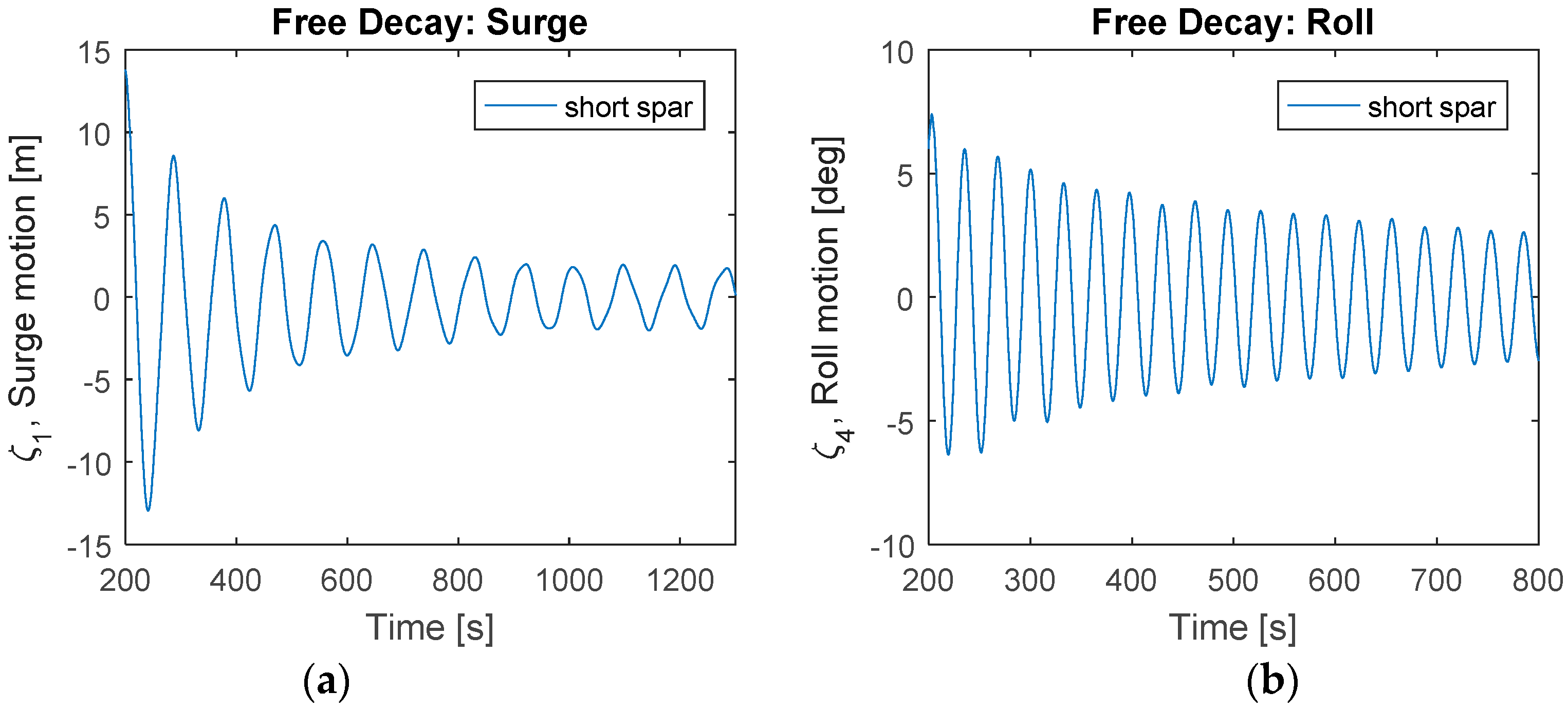
The natural periods of the short spar and deep spar are presented in Table 5. For the natural periods of the deep spar VAWT, we can refer to Cheng et al. [13]. Free decay tests were applied to identify the natural periods of the short spar VAWT (Figure 4). Free decay tests were carried out in calm water. The wind turbine was parked without any aerodynamic loads on the rotor, and one specified force acted in each of six degrees of direction with a very short period (200 s) to simulate its dynamic response.
For surge and sway, the natural periods of both spars are quite long. The natural period of the short spar is smaller than that of the deep spar, since the restoring stiffness of the short spar is larger due to the stiffer and shorter mooring lines. In heave, both spars are close to the upper limit of the wave periods. The short spar has a larger waterline area, and its natural period is smaller than that of the deep spar. For roll and pitch, the natural periods of both spars locate outside the range of wave periods; hence, the wave-induced resonant motions may not be substantial. However, both spars are situated inside the range of wave periods in yaw motion. Significant motion may be expected to occur in the yaw direction.

3.2. Wind Turbine Performance

The rotor speed of the short spar VAWT and deep spar VAWT under all loading cases are plotted in Figure 5 and summarized in Table 6. A good agreement in rotor speed between the short and deep spar are shown in this figure. The rotor speed principally increases as the wind speed increases, but the rotor speed starts to decrease with the rising wind velocity after it reaches the rated speed. This mechanism can be explained by the fact that a Proportional Integral (PI) generator controller is employed to decrease the rotational speed in order to keep the power approximately constant [9].
The rotor rotation causes the aerodynamic loads on the spar VAWTs. One of the most prominent dynamic loads in VAWTs is the 2P loading. The blade shadowing effect and the variation in torque lead to 2P loading, which is a periodic loading. The 2P frequency is twice the 1P frequency since the Darrieus wind turbine has two blades. The 2P loading can decompose into thrust and lateral force which are parallel and normal to the wind flow direction, respectively.
A snapshot of the comparison between the 2P loading in the short spar VAWT and deep spar VAWT under rated speed (LC3) from 2000 to 2020 s is shown in Figure 6. Generally, the amplitudes of thrust and lateral force are similar. The mean value of lateral force is approximately zero, but the thrust fluctuates between zero and double the mean value. In addition, the amplitude of the short spar VAWT is almost the same as that of the deep spar VAWT in both thrust and lateral force, but the phase among these two spars is different. The average periods of thrust and lateral force are each around 6 s, which correspond to the 2P frequency.
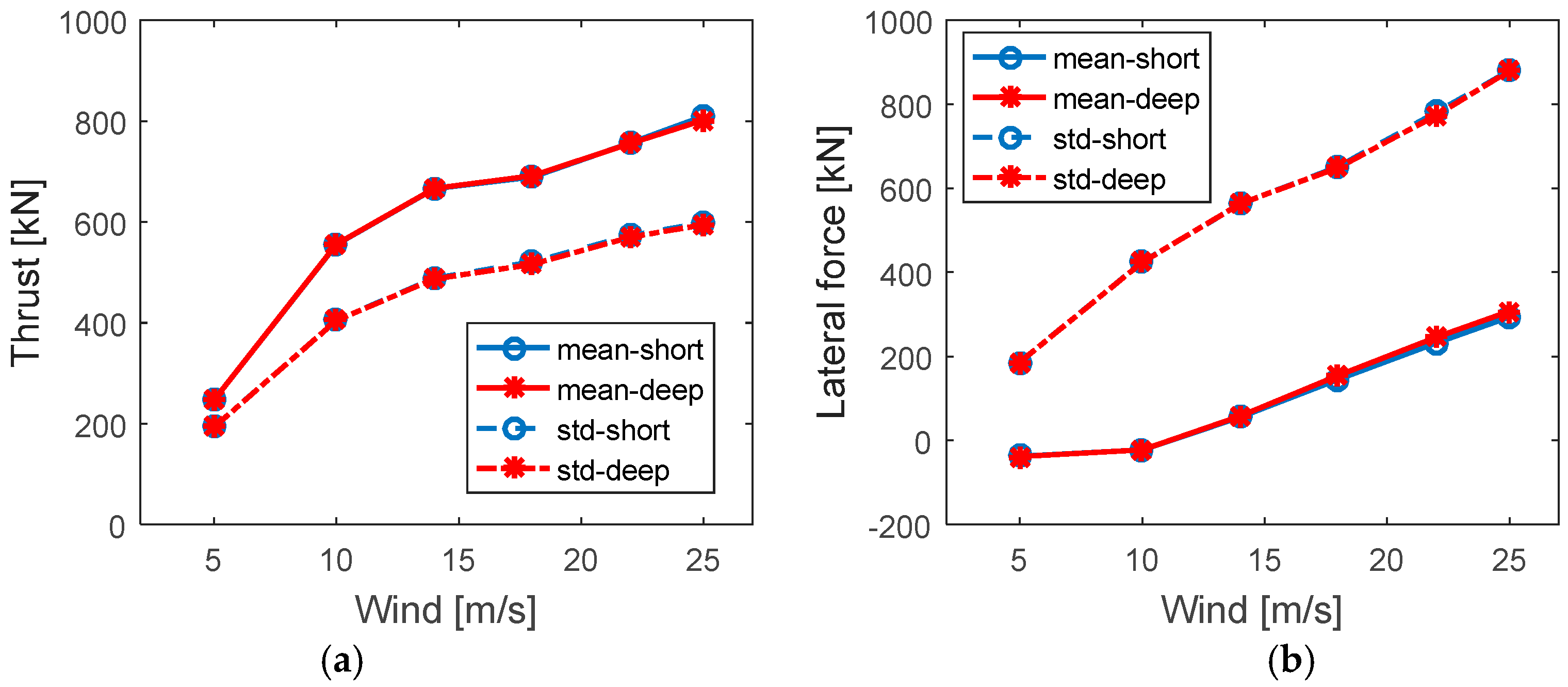
Figure 7 displays the statistical comparisons of the thrust and lateral force for both spars under all loading cases. For simplicity, the results are plotted with the mean wind speed only even the loading includes the turbulent wind and irregular wave simultaneously. Both the comparisons indicate a good agreement between the short spar and deep spar. The mean values and standard deviations of the thrust and lateral force increase separately as the wind speed increases.
In addition, the variation of relative speed along the height of the VAWT is included in this simulation. Since both the spar VAWTs carry the same 5 MW Darrieus rotor and withstand the same environmental loadings, the aerodynamic effect of wind turbines in both models could be expected to be similar. Therefore, a further discussion about the aerodynamic effect is not shown in this work.
The generator power production of the short spar VAWT and deep spar VAWT under all environmental conditions is plotted in Figure 8. This power curve shows the mean generator power production with the error bar indicating the standard deviations of the mean values. The short spar curve has a good agreement with the deep spar performance. The power production of both the short and deep spar VAWTs increases as the wind speed increases. While the wind speed exceeds the rated speed (14 m/s), the mean power production will be higher than 5 MW but remain approximately a constant value. The cause of this fact is that a PI-based generator torque controller is implemented to maintain an approximately constant generator power when the rated operation point is reached [10].

3.3. Platform Motion

The platform motion can be normally divided into six degrees of freedom, which includes surge, sway, heave, roll, pitch, and yaw motions. In this paper, the heave is defined in global coordinates with the Z axis along the axial direction of the spar, and the surge is in the X axis which is parallel to the wind and wave direction (
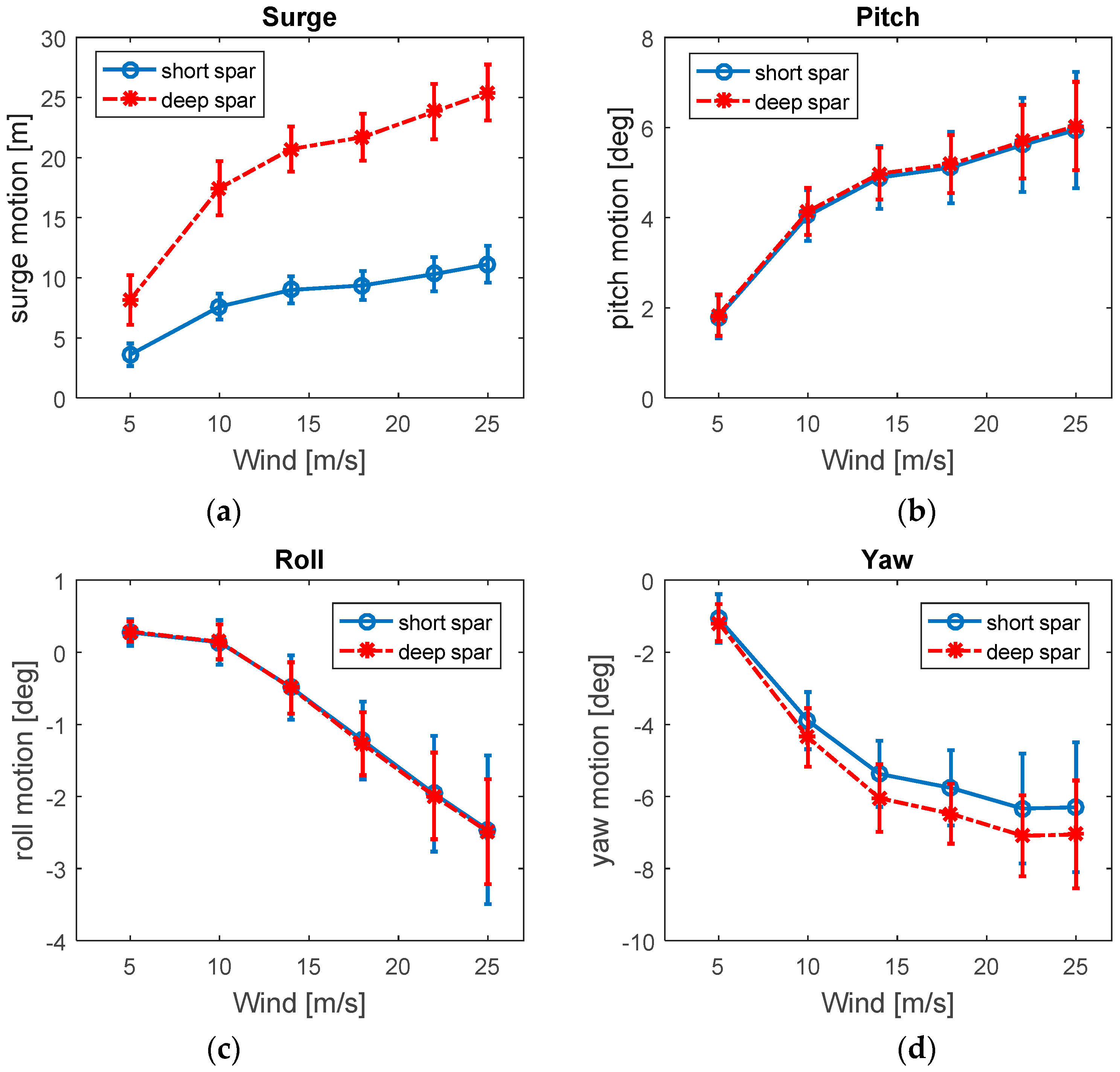
Figure 2). The comparisons of the mean values and standard deviations of the global motions under different environmental conditions between the short and deep spar VAWTs are shown in Figure 9. Similarly, the mean global motion is shown with error bars indicating the standard deviations of the mean values. Generally, the mean values of the global motions increase as the wind speed increases. Since more powerful wind will cause larger thrust and lateral force (Figure 7), stronger motions will be easily induced.
In comparing the two models in pitch and roll motions, the mean values of the short spar have good agreement with those of the deep spar. The standard deviations of the short spar are a little larger than those of the deep spar. The mean values and standard deviations of surge motion of the deep spar VAWT are significantly larger than those of the short spar VAWT. Since the surge motions were derived at the mean water level, a lower center of gravity (COG) of the deep spar VAWT with the same pitch angle could lead to larger motion in surge. However, the mean values of the deep spar VAWT in yaw motion give more significant responses than those of the short spar VAWT. This could be the reason that the natural periods of the deep spar VAWT in yaw motion are much closer to the dominating wave energy.
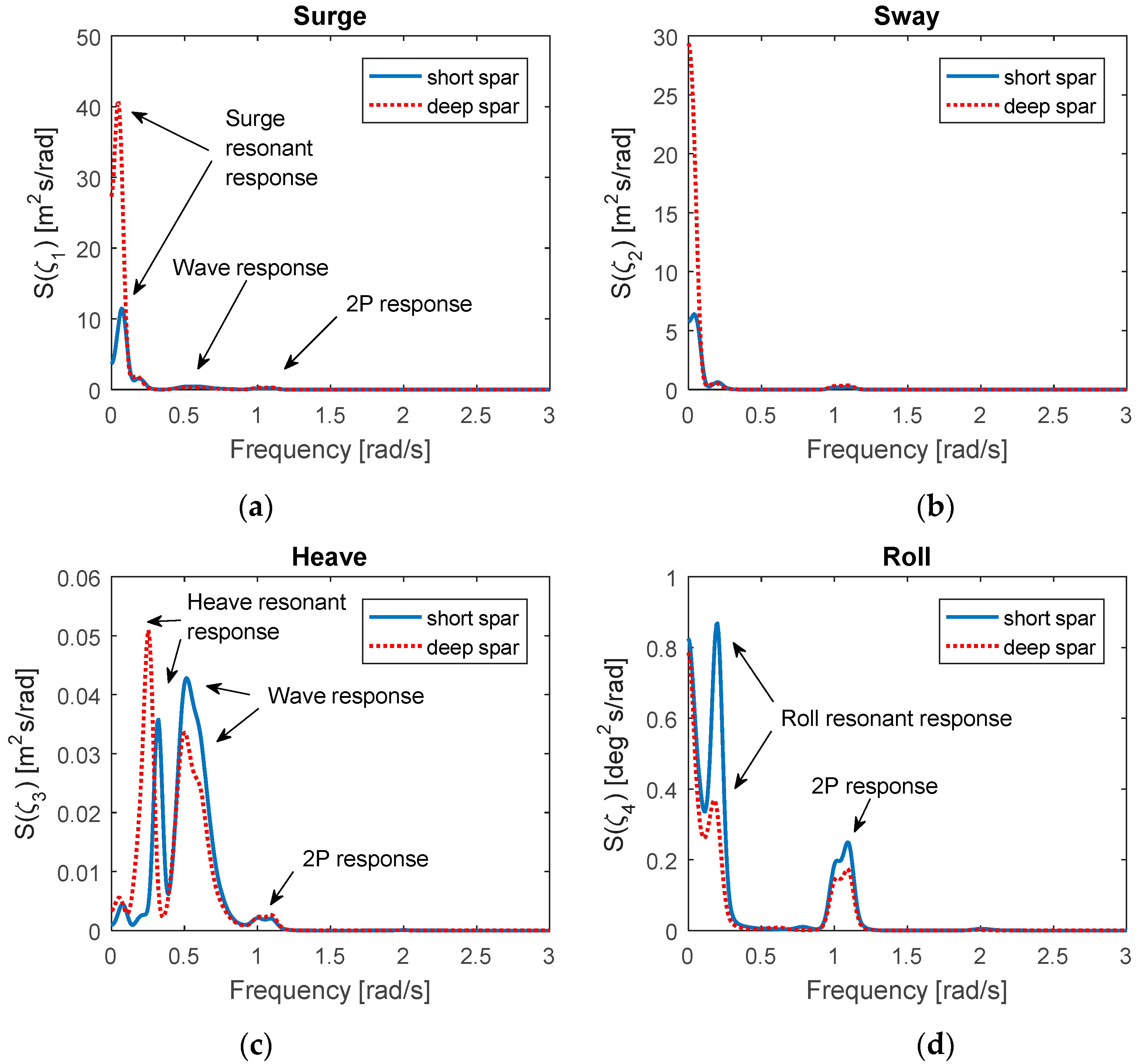
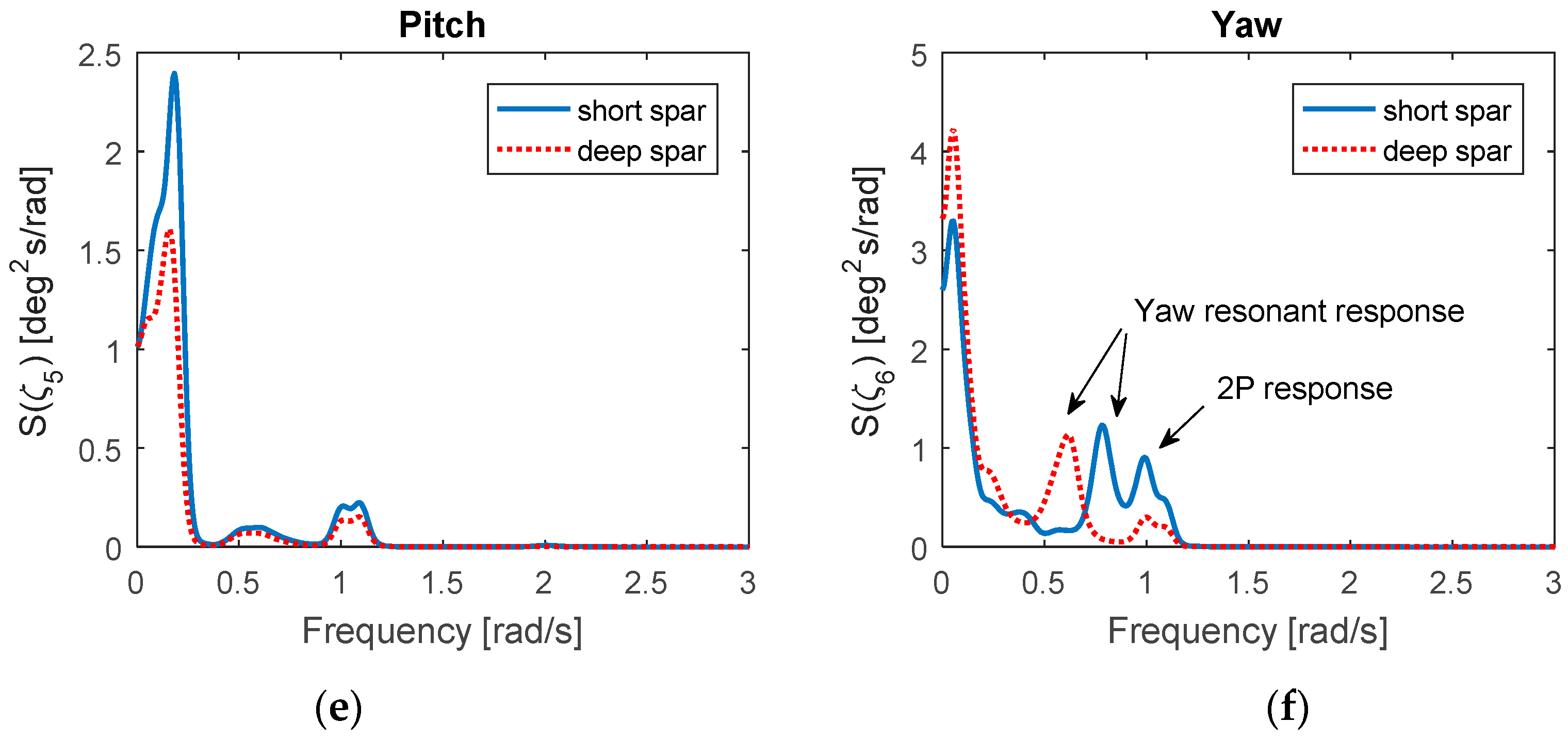
The power spectra are used to analyze the time series of physical motions, which can reveal the frequency contributions in the standard deviation. A parzen window function is of benefit to filter or smooth the variation of the spectra in the frequency domain. The comparison of power spectra in six degrees of freedom between the short and deep spar under rated wind speed (LC3) can be found in Figure 10. Basically, these dynamic responses are mainly controlled by the resonant frequency, wave frequency, and 2P frequency. The short spar VAWT and deep spar VAWT have similar spectra distribution except in the heave motion. The heave motions of deep spar VAWT are dominated by its resonant response, whereas the wave-frequency-induced heave response is more prominent in the short spar.
In surge and sway motion, the deep spar VAWT has much larger resonant response. Typically, the dynamic response is determined through mass of inertia, damping, and stiffness of the system. The viscous damping terms were considered in both spar VAWT models. Owning to less discrepancy between the added mass of both spar VAWTs in surge/sway, the stiffness term becomes the key factor. Since the longer mooring lines of the deep spar VAWT result in softer restoring stiffness in the horizontal direction, a larger spectrum of surge/sway motions occur. In addition, the dominating spectra values of the short spar VAWT in roll, pitch, and yaw motion are larger than those of the deep spar VAWT. Due to a shorter metacenter height and softer restoring stiffness in roll/pitch, the higher standard deviations and larger spectrum values in roll/pitch motion could be expected from the short spar VAWT.
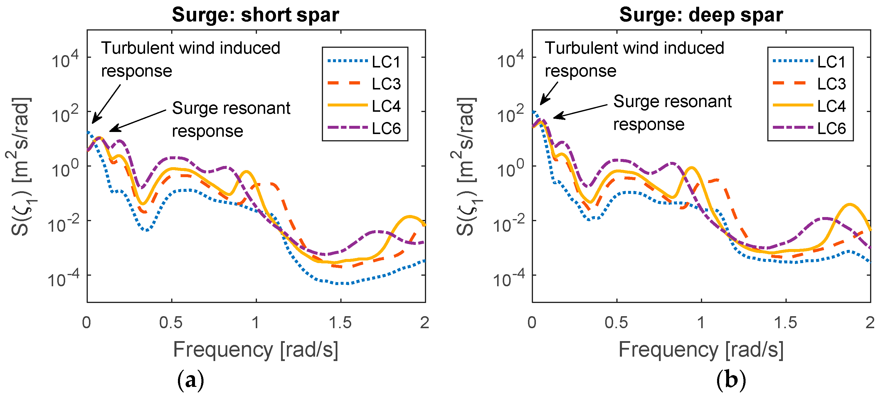
The power spectra of the short and deep spar VAWTs in surge under each environmental loading are plotted in Figure 11. It can be found that the low frequency induced by turbulent wind responses is dominating when the wind speed is below the rated speed (LC3). The surge resonant response dominates when the wind speed is above the rated speed and is larger than the wave response and 2P response. Overall, the dominating spectra values in the deep spar VAWT are higher than those of the short spar VAWT, and the larger standard deviations of the deep spar in surge motion can also be found in Figure 9a.

3.4. Tower Base Bending Moments

The tower base bending moment is considered in this study. The bending moment is mainly induced by the aerodynamic force on the rotor and the downward gravity force of its self-weight owing to the tilted tower. The fore–aft and side–side bending moments are important indices to assess the structural performance of the wind turbine, as the aerodynamic forces vary with the azimuthal angle and cause large variation on these bending moments [9]. The fore–aft is parallel to the wind flow direction, and side–side is perpendicular to the wind flow.
Figure 12 compares the respective mean values, maxima values, and the standard deviations of fore–aft and side–side bending moments for the short and deep spar VAWTs. In this study, the maximum value in each loading case was derived from the mean of maximal numbers for each random seed simulation in the time domain. Overall, the comparison shows a good agreement between the short spar and deep spar. The mean, maximum, and standard deviations of the bending moment in both fore–aft and side–side directions increase as wind velocity increases.
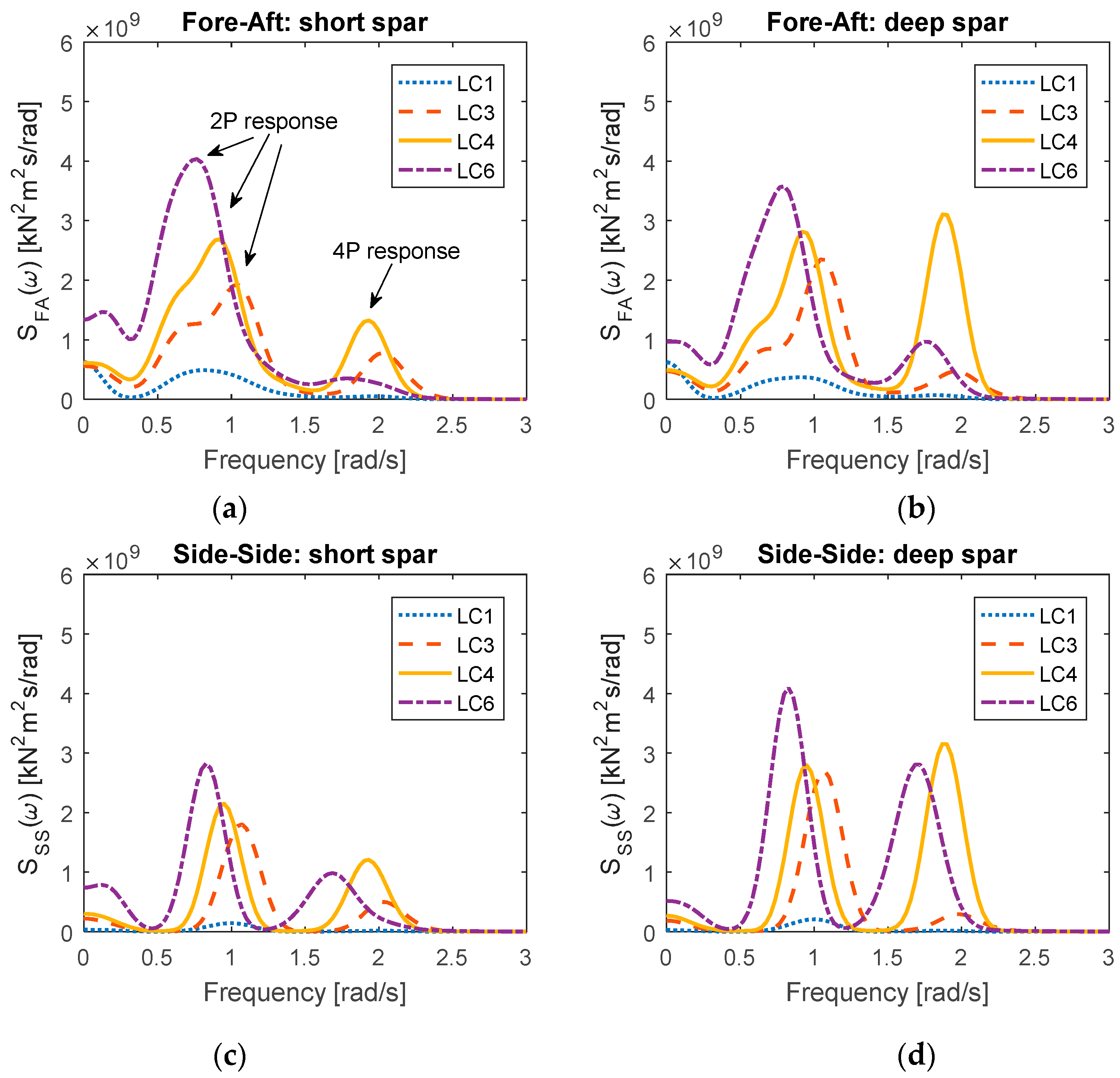
The power spectra of the tower base bending moment under all environmental conditions for the short and deep spar VAWTs are shown in Figure 13. Whether in the short spar VAWT or the deep spar VAWT, 2P responses are almost dominating for all loading conditions. The response at 4P frequency will become significant when the wind speed is over the rated speed (LC4 to LC6). The excitation may result from the structural resonance at 4P frequency when the environmental condition exceeds loading case LC3. The corresponding maxima spectra values for each loading case increase as wind velocity increases. The 2P responses of the deep spar VAWT in the tower base side–side bending moment are larger than those of the short spar VAWT, as are 2P responses in the tower base fore–aft bending moment for most loading cases. An exception is LC6 with Uw = 25 m/s and Hs = 6.02 m, under which the 2P responses of the short spar VAWT are larger than the corresponding values of the deep spar VAWT in the tower base fore–aft bending moments.

3.5. Mooring Line Tensiion

The catenary mooring system is used for both the short and deep spar VAWTs. The main purpose of the mooring system is to maintain the floater in the proper position, and the delta line can provide yaw stiffness. For a conservative design approach, the turbulent wind and irregular wave are aligned in the same direction (+X global motion) in this study; hence, Mooring Line 1 will have the main role in withstanding most of the external force (Figure 2). The tension of Mooring Line 1 is measured at the anchor point and is the sum of tension in the upper line, clump mass, and lower line.
Figure 14 presents the mean values, maxima values, and standard deviations of Mooring Line 1 for the short and deep spar VAWTs under all environmental conditions. Generally, the mean, maxima values, and standard deviations increase as the wind speed and significant wave height increase. The mean values of tension for the deep spar VAWT are larger than those of the short spar VAWT, but the maxima values and standard deviations of the deep spar VAWT are smaller.
Figure 15 compares the respective spectra of tension in Mooring Line 1 between the short spar and deep spar VAWTs under all the loading cases. Overall, the distribution of tension spectra in Mooring Line 1 for the short spar VAWT agrees well with that of the deep spar VAWT. The similarity between the short and deep spar VAWTs in the tension spectra is that the dominating wind-induced response increases as the wind speed and irregular wave state increase. However, the dominating spectra values of the short spar VAWT are significantly higher, as are the standard deviations of the tension of Mooring Line 1.

4. Conclusions

This paper presents a comparative study of the dynamic response of the short spar and deep spar VAWTs at the different water depths through a fully coupled SIMO-RIFLEX-DMS simulation tool. The results indicate that the short spar VAWT is a feasible concept at moderate water depths (150 m). Several main conclusions in this study are given below.
  • The 2P loading and the generator power production of the short spar VAWT agree well with those of the deep spar VAWT for all loading conditions. Both the 2P loading and power production increase as the wind speed increases, but the power production will remain an approximately constant value when the rated speed is reached. We conclude that the short spar VAWT at moderate water depth exhibits as good a performance in power generation as does the deep spar VAWT in deep water.
  • In general, the tendency to the distribution of platform motions for both spar VAWTs are similar. However, the mean value and standard deviations of surge and sway for the deep spar VAWT are significantly larger than those of the short spar VAWT. The lower center of gravity of the deep spar VAWT results in larger responses in surge and sway.
  • The comparison of the tower base bending moment shows a good agreement between the short spar VAWT and the deep spar VAWT. The mean, maxima values, and standard deviations of bending moments in both fore–aft and side–side directions increase as wind speed increases. Both spar VAWTs are dominated by the 2P response in bending moment spectra.
  • The tension of Mooring Line 1 is designed to withstand most of external loading in this study, since its layout aligns in the same direction as the wind and waves. The turbulence wind-induced response is particularly prominent for both spar VAWTs. The short spar VAWT displays higher standard deviations in the tension of Mooring Line 1, and its response spectra values are substantially larger than those of the deep spar.

Acknowledgments

Zhengshun Cheng appreciates the support from State Key Laboratory of Hydraulic Engineering Simulation and Safety (HESS-1710), Tianjin University, China.

Author Contributions

Kai Wang and Muk Chen Ong conceived and designed the numerical study; Kai Wang and Zhengshun Cheng contributed analysis tools; Ting Rui Wen performed the simulations and analyzed the data under Kai Wang’s supervision; Ting Rui Wen wrote the paper; Kai Wang, Zhengshun Cheng and Muk Chen Ong gave comments and revised this paper.

Conflicts of Interest

The authors declare no conflict of interest.

Abbreviations

1POne per Revolution
2PTwo per Revolution
COBCenter of Buoyancy
COGCenter of Gravity
COMCenter of Mass
HAWTHorizontal Axis Wind Turbine
MWLMean Water Level
TLPTension Leg Platform
VAWTVertical Axis Wind Turbine
WADAMWave Analysis by Diffraction and Morison Theory
DMSDouble-Multiple Streamtube
PIProportional Integral

References

  1. DNV GL, AS. Global Performance Analysis of Deepwater Floating Structures; Recommended Practice, DNVGL-RP-F205; DNV GL AS: Oslo, Norway, 2017. [Google Scholar]
  2. JWPA. Offshore Wind Power Development in Japan, 2017. Japan Wind Power Association. Available online: https://jwpa.jp (accessed on 7 September 2017).
  3. Karimirad, M.; Moan, T. Feasibility of the Application of a Spar-type Wind Turbine at a Moderate Water Depth. Energy Procedia 2012, 24 (Suppl. C), 340–350. [Google Scholar] [CrossRef]
  4. Karimirad, M.; Moan, T. Comparative Study of Spar-Type Wind Turbines in Deep and Moderate Water Depths. In Proceedings of the ASME 2012 31st International Conference on Ocean, Offshore and Arctic Engineering, Rio de Janeiro, Brazil, 1–6 July 2012; pp. 551–560. [Google Scholar]
  5. Paulsen, U.S.; Pedersen, T.F.; Madsen, H.A.; Enevoldsen, K.; Nielsen, P.H.; Hattel, J.H.; Zanne, L.; Battisti, L.; Brighenti, A.; Lacaze, M.; et al. Deepwind—An Innovative Wind Turbine Concept for Offshore. In Proceedings of the European Wind Energy Association (EWEA) Annual Event, Brussels, Belgium, 14–17 March 2011. [Google Scholar]
  6. GWIND. Spinwind1—Prototype Launch. 2013. Available online: http://www.gwind.no/?p=212 (accessed on 20 December 2017).
  7. Paulsen, U.S.; Vita, L.; Madsen, H.A.; Hattel, J.; Ritchie, E.; Leban, K.M.; Berthelsen, P.A.; Carstensen, S. 1st DeepWind 5 MW Baseline design. Energy Procedia 2012, 24, 27–35. [Google Scholar] [CrossRef]
  8. Paulsen, U.S.; Madsen, H.A.; Hattel, J.H.; Baran, I.; Nielsen, P.H. Design Optimization of a 5 MW Floating Offshore Vertical-axis Wind Turbine. Energy Procedia 2013, 35, 22–32. [Google Scholar] [CrossRef] [Green Version]
  9. Wang, K. Modeling and Dynamic Analysis of a Semi-Submersible Floating Vertical Axis Wind Turbine. Ph.D. Thesis, Norwegian University of Science and Technology, Trondheim, Norway, 2015. [Google Scholar]
  10. Cheng, Z. Integrated Dynamic Analysis of Floating Vertical Axis Wind Turbines. Ph.D. Thesis, Norwegian University of Science and Technology, Trondheim, Norway, 2016. [Google Scholar]
  11. Ugochukwu, I.J. Structural Dynamic Analysis of Semi-Submersible Floating Vertical Axis Wind Turbines. Master’s Thesis, University of Stavanger, Stavanger, Norway, 2016. [Google Scholar]
  12. Liu, L.; Guo, Y.; Jin, W.; Yuan, R. Motion Performances of a 5 MW VAWT Supported by Spar Floating Foundation With Heave Plates. In Proceedings of the ASME 2017 36th International Conference on Ocean, Offshore and Arctic Engineering, Trondheim, Norway, 25–30 June 2017; p. V010T09A086. [Google Scholar] [CrossRef]
  13. Cheng, Z.; Wang, K.; Gao, Z.; Moan, T. Dynamic Response Analysis of Three Floating Wind Turbine Concepts with a Two-Bladed Darrieus Rotor. J. Ocean Wind Energy 2015, 2, 213–222. [Google Scholar] [CrossRef]
  14. Wang, K.; Moan, T.; Hansen, M.O.L. A Method for Modeling of Floating Vertical Axis Wind Turbine. In Proceedings of the 32nd International Conference on Ocean, Offshore and Arctic Engineering, Nantes, France, 9–14 June 2013; p. V008T09A016. [Google Scholar] [CrossRef]
  15. Cheng, Z.; Madsen, H.A.; Gao, Z.; Moan, T. A fully coupled method for numerical modeling and dynamic analysis of floating vertical axis wind turbines. Renew. Energy 2017, 107, 604–619. [Google Scholar] [CrossRef]
  16. SINTEF Ocean. SIMO 4.10.1 User Guide; SINTEF Ocean: Trondheim, Norway, 2017. [Google Scholar]
  17. SINTEF Ocean. RIFLEX 4.10.1 User Guide; SINTEF Ocean: Trondheim, Norway, 2017. [Google Scholar]
  18. Wang, K.; Hansen, M.O.L.; Moan, T. Model improvements for evaluating the effect of tower tilting on the aerodynamics of a vertical axis wind turbine. Wind Energy 2015, 18, 91–110. [Google Scholar] [CrossRef]
  19. Jonkman, B.J.; Kilcher, L. TurbSim User’s Guide: Version 1.06.00; National Renewable Energy Laboratory: Golden, CO, USA, 2012. [Google Scholar]
  20. Johannessen, K.; Meling, T.S.; Haver, S. Joint Distribution for Wind and Waves in the Northern North Sea. In Proceedings of the Eleventh International Offshore and Polar Engineering Conference, Stavanger, Norway, 17–22 June 2001. [Google Scholar]
Figure 1. The diagram of the deep spar and short spar vertical-axis wind turbines (VAWTs) in deep and moderate water. Here MWL means mean water level.
Energies 11 00555 g001
Figure 2. The diagram of the mooring system for the short spar and deep spar VAWTs.
Energies 11 00555 g002
Figure 3. Computation flow chart for the coupled model (reproduced from Wang [9]).
Energies 11 00555 g003
Figure 4. Free decay tests for the short spar VAWT: (a) Surge; (b) Roll.
Energies 11 00555 g004
Figure 5. Mean rotor speed for the short spar VAWT and deep spar VAWT with error bar representing the standard deviation.
Energies 11 00555 g005
Figure 6. Comparison of time series in 2P loading for short spar and deep spar VAWTs under LC3 with Uw = 14 m/s, Hs = 3.62 m, Tp = 10.29 s: (a) Thrust; (b) Lateral force.
Energies 11 00555 g006
Figure 7. Comparison of mean values and standard deviations of the 2P loading for the short and deep spar VAWTs under all loading cases: (a) Thrust; (b) Lateral force.
Energies 11 00555 g007
Figure 8. Mean power production for the short spar VAWT and deep spar VAWT with error bar representing the standard deviation.
Energies 11 00555 g008
Figure 9. Comparison of mean values with error bar indicating the standard deviation in surge, heave, roll, and yaw motions for the short and deep spar VAWT: (a) Surge; (b) Pitch; (c) Roll; (d) Yaw.
Energies 11 00555 g009
Figure 10. Comparison of power spectra in six degrees of freedom for the short and deep spar VAWT under LC3 with Uw = 14 m/s, Hs = 3.62 m, Tp = 10.29 s: (a) Surge; (b) Sway; (c) Heave; (d) Roll; (e) Pitch; (f) Yaw.
Energies 11 00555 g010aEnergies 11 00555 g010b
Figure 11. Power spectra in surge under all loading cases: (a) Short spar; (b) Deep spar.
Energies 11 00555 g011
Figure 12. Statistics of tower base bending moment for the short spar and deep spar VAWTs: (a) Mean values in fore–aft; (b) Mean values in side–side; (c) Maxima values in fore–aft; (d) Maxima values in side–side; (e) Standard deviations in fore–aft; (f) Standard deviations in side–side.
Energies 11 00555 g012
Figure 13. Power spectra of tower base bending moment under all loading cases: (a) Short spar VAWT in fore–aft direction; (b) Deep spar VAWT in fore–aft direction; (c) Short spar VAWT in side–side direction; (d) Deep spar VAWT in side–side direction.
Energies 11 00555 g013
Figure 14. Statistics of the tension of Mooring Line 1 for the short spar and deep spar VAWTs.
Energies 11 00555 g014
Figure 15. Power spectra of the tension in Mooring Line 1 under all loading cases: (a) Short spar VAWT; (b) Deep spar VAWT.
Energies 11 00555 g015
Table 1. Specifications of the Darrieus 5 MW wind turbine [13].
ItemUnitValue
Rated power(MW)5
Rotor height, root to root(m)129.56
Rotor radius(m)63.74
Chord length(m)7.45
Airfoil section(-)NACA 0018
Cut-in, rated, cut-out wind speed(m/s)5, 14, 25
Rated rotational speed(rpm)5.26
Total mass, incl. rotor and tower(kg)754,226
Center of mass(m)(0, 0, 75.6)
Table 2. Properties of the Deep Spar and Short Spar.
ItemUnitDeep SparShort Spar
Water depth (m)320150
Draft(m)12080
Waterline diameter(m)6.59
Diameter at bottom(m)9.412
Hull mass, including ballast and generator(ton)7308.37962.8
COM location below MSL 1(m)−89.76−62.86
COG location below MSL 2(m)−74.29−50.88
Displacement(m3)80278642
COB location below MSL3(m)−62.06−41.68
Mass moment of inertia in roll and pitch, IXX and IYY(ton · m2) 3.362 × 10 7 3.599 × 10 7
Mass moment of inertia in yaw, IZZ(ton · m2) 1.588 × 10 5 1.889 × 10 5
1 Center of Mass (COM) of floater only includes spar, ballast, and generator. 2 Center of Gravity (COG) of floater includes turbine, rotor, tower, and spar (ballast). 3 COB represents the center of buoyancy; MSL refers to the mean seawater level.
Table 3. The properties of mooring system components.
TypeComponentLength (m)Mass (kg/m)Axial Stiffness (kN)
Deep SparDelta line5042.5200,000
Upper line25042.580,000
Clump mass217,25380,000
Lower line60042.560,000
Short SparDelta line5042.5200,000
Upper line12542.580,000
Clump mass217,25380,000
Lower line25042.560,000
Table 4. Environmental loading for normal operating conditions [9].
Load Case (LC)Uw (m/s) 1TI (-)Hs (m)Tp (s)
LC150.2242.109.74
LC2100.1572.889.98
LC3140.1383.6210.29
LC4180.1274.4410.66
LC5220.1215.3211.06
LC6250.1176.0211.38
1 The wind speed is the mean speed at the reference height of 79.78 m above MWL.
Table 5. Natural periods of short and deep spar VAWTs.
MotionDeep Spar 1 (s)Short Spar (s)
Surge/Sway130.889.8
Heave27.321.6
Roll/Pitch34.532.5
Yaw8.57.1
1 The natural periods of the deep spar were derived from Cheng et al. [13].
Table 6. Mean rotor speed for all loading cases.
Load CaseMean Rotor Speed 1 (rad/s)2P Frequency 2 (rad/s)2P Period (s)
LC10.4620.9256.79
LC20.5511.1025.70
LC30.5281.0565.95
LC40.4720.9446.66
LC50.4350.8707.23
LC60.4100.8197.67
1 The mean rotor speed can represent the 1P frequency for each load cases. 2 2P frequency is twice the 1P frequency and is the inverse of the 2P period.

